

Page 1

Dell PowerEdge T430
Owner's Manual
Regulatory Model: E30S Series
Regulatory Type: E30S001
Page 2

Notes, Cautions, and Warnings
NOTE: A NOTE indicates important information that helps you make better use of your computer.
CAUTION: A CAUTION indicates either potential damage to hardware or loss of data and tells you
how to avoid the problem.
WARNING: A WARNING indicates a potential for property damage, personal injury, or death.
Copyright © 2014 Dell Inc. All rights reserved. This product is protected by U.S. and international copyright and
intellectual property laws. Dell™ and the Dell logo are trademarks of Dell Inc. in the United States and/or other
jurisdictions. All other marks and names mentioned herein may be trademarks of their respective companies.
2014 - 10
Rev. A00
Page 3

Contents
1 About your system................................................................................................ 9
Front-panel features and indicators...................................................................................................10
LCD panel features..............................................................................................................................16
Home screen................................................................................................................................. 16
Setup menu....................................................................................................................................17
View menu..................................................................................................................................... 17
Diagnostic indicators...........................................................................................................................17
Hard-drive indicator codes................................................................................................................. 19
Back-panel features and indicators................................................................................................... 20
NIC indicator codes............................................................................................................................ 22
Indicator codes for redundant power supply.................................................................................... 22
Indicator codes for non-redundant power supply............................................................................24
Documentation matrix........................................................................................................................25
Quick Resource Locator............................................................................................................... 25
2 Performing initial system configuration ........................................................27
Setting up your system........................................................................................................................27
Setting up and configuring the iDRAC IP address .............................................................................27
Logging in to iDRAC............................................................................................................................27
Installing the operating system.......................................................................................................... 28
Managing your system remotely........................................................................................................28
Downloading and installing drivers and firmware............................................................................. 28
3 Pre-operating system management applications........................................30
Navigation keys................................................................................................................................... 30
About System Setup............................................................................................................................30
Entering System Setup...................................................................................................................31
System Setup Main Menu.............................................................................................................. 31
System BIOS screen.......................................................................................................................31
System Information screen...........................................................................................................32
Memory Settings screen................................................................................................................32
Processor Settings screen.............................................................................................................33
SATA Settings screen.....................................................................................................................34
Boot Settings screen..................................................................................................................... 37
Network Settings screen............................................................................................................... 37
Integrated Devices screen details.................................................................................................38
Serial Communication screen...................................................................................................... 39
System Profile Settings screen..................................................................................................... 40
Page 4

System Security Settings screen................................................................................................... 41
Miscellaneous Settings screen......................................................................................................43
About Boot Manager...........................................................................................................................43
Entering Boot Manager ................................................................................................................ 43
Boot Manager main menu............................................................................................................ 43
About Dell Lifecycle Controller..........................................................................................................44
Changing the boot order....................................................................................................................44
Choosing the system boot mode...................................................................................................... 44
Assigning a system and setup password............................................................................................45
Using your system password to secure your system........................................................................ 46
Deleting or changing an existing system password and setup password........................................46
Operating with a setup password enabled........................................................................................ 47
Embedded system management........................................................................................................47
iDRAC Settings utility...........................................................................................................................47
Entering the iDRAC Settings utility................................................................................................47
Changing the Thermal Settings....................................................................................................48
4 Installing and removing system components...............................................49
Safety instructions...............................................................................................................................49
Before working inside your system....................................................................................................49
After working inside your system....................................................................................................... 49
Recommended tools.......................................................................................................................... 50
Front bezel (optional)..........................................................................................................................50
Installing the front bezel............................................................................................................... 50
Removing the front bezel..............................................................................................................51
System feet.......................................................................................................................................... 51
Removing the system feet.............................................................................................................51
Installing the system feet.............................................................................................................. 52
Caster wheels (optional)—tower mode..............................................................................................53
Installing caster wheels................................................................................................................. 53
Removing caster wheels...............................................................................................................54
Removing the system cover............................................................................................................... 55
Installing the system cover................................................................................................................. 56
Inside the system.................................................................................................................................56
Optical drives and tape drives (optional)............................................................................................57
Removing the optical drive or tape drive..................................................................................... 58
Installing the optical drive or tape drive....................................................................................... 61
Cooling shroud....................................................................................................................................61
Removing the cooling shroud.......................................................................................................61
Installing the cooling shroud........................................................................................................ 62
Hot-swappable hard drives................................................................................................................ 63
Removing a hot-swap hard drive................................................................................................. 64
Page 5

Installing a hot-swap hard drive................................................................................................... 65
Removing a hard-drive blank........................................................................................................65
Installing a hard-drive blank......................................................................................................... 66
Installing a 2.5 inch hard drive into a 3.5 inch hard-drive adapter..............................................67
Removing a 2.5 inch hard drive from a 3.5 inch hard-drive adapter..........................................68
Installing a hard-drive adapter into a hard-drive carrier............................................................. 68
Removing a hard-drive adapter from a hard-drive carrier..........................................................69
Removing a hard drive from a hard-drive carrier........................................................................ 69
Installing a hard drive into a hard-drive carrier............................................................................70
Cabled hard drives.............................................................................................................................. 70
Removing the internal hard-drive bay.......................................................................................... 71
Installing the internal hard-drive bay............................................................................................72
Removing a cabled hard drive...................................................................................................... 72
Installing a cabled hard drive........................................................................................................ 76
Hard-drive backplane..........................................................................................................................76
Removing the hard-drive backplane ........................................................................................... 77
Installing the hard-drive backplane..............................................................................................82
Four-slot hard-drive blank..................................................................................................................82
Removing a four-slot hard-drive blank........................................................................................82
Installing a four-slot hard-drive blank..........................................................................................83
System memory.................................................................................................................................. 84
General memory module installation guidelines.........................................................................86
Mode-specific guidelines..............................................................................................................86
Sample memory configurations................................................................................................... 87
Removing memory modules........................................................................................................89
Installing memory modules..........................................................................................................90
Cooling fans........................................................................................................................................ 92
Removing the internal cooling fan...............................................................................................92
Installing the internal cooling fan.................................................................................................93
Removing the external cooling fan ............................................................................................. 94
Installing the external cooling fan................................................................................................ 95
Internal USB memory key (optional).................................................................................................. 96
Replacing the internal USB key.....................................................................................................96
Expansion card holder........................................................................................................................ 97
Removing the expansion card holder.......................................................................................... 97
Installing the expansion card holder............................................................................................ 98
Expansion cards.................................................................................................................................. 98
Expansion card installation guidelines......................................................................................... 99
GPU card installation guidelines.................................................................................................100
Removing an expansion card..................................................................................................... 100
Installing an expansion card....................................................................................................... 102
Removing a GPU card.................................................................................................................103
Page 6

Installing a GPU card...................................................................................................................104
iDRAC ports card (optional)..............................................................................................................105
Removing the iDRAC ports card.................................................................................................105
Installing the iDRAC ports card...................................................................................................106
Replacing an SD vFlash media card............................................................................................107
Internal dual SD module...................................................................................................................108
Removing the internal dual SD module .................................................................................... 108
Installing the internal dual SD module .......................................................................................110
Internal SD card................................................................................................................................. 110
Removing an internal SD card.....................................................................................................110
Installing an internal SD card....................................................................................................... 111
Processors.......................................................................................................................................... 111
Removing a processor.................................................................................................................112
Installing a processor...................................................................................................................116
Redundant AC power supply............................................................................................................ 118
Hot Spare feature.........................................................................................................................118
Removing a redundant AC power supply...................................................................................119
Installing a redundant AC power supply ................................................................................... 120
Removing the power supply unit blank...................................................................................... 121
Installing the power supply unit blank........................................................................................122
Replacing the power supply divider............................................................................................122
Non-redundant AC power supply.................................................................................................... 123
Removing a non-redundant AC power supply.......................................................................... 124
Installing a non-redundant AC power supply............................................................................ 125
Power interposer board.................................................................................................................... 126
Removing the power interposer board...................................................................................... 126
Installing the power interposer board........................................................................................ 127
System battery...................................................................................................................................128
Replacing the system battery......................................................................................................128
Control panel assembly.................................................................................................................... 129
Removing the control panel assembly.......................................................................................129
Installing the control panel assembly......................................................................................... 131
Removing the control panel assembly cover.............................................................................132
Installing the control panel assembly cover...............................................................................133
Removing the control-panel board............................................................................................134
Installing the control-panel board..............................................................................................135
Removing the LCD module........................................................................................................ 136
Installing the LCD module...........................................................................................................137
Removing the VGA module........................................................................................................ 138
Installing the VGA module.......................................................................................................... 139
System board.....................................................................................................................................139
Removing the system board....................................................................................................... 139
Page 7

Installing the system board.........................................................................................................143
Restoring the Service Tag using Easy Restore........................................................................... 144
Entering the system Service Tag using System Setup............................................................... 144
Trusted Platform Module..................................................................................................................145
Installing the Trusted Platform Module .....................................................................................145
Re-enabling the TPM for BitLocker users.................................................................................. 146
Re-enabling the TPM for TXT users........................................................................................... 146
System top cover...............................................................................................................................147
Removing the system top cover.................................................................................................147
Installing the system top cover...................................................................................................148
5 Converting the system from tower mode to rack mode.......................... 149
Safety instructions.............................................................................................................................149
Preparing a system for conversion from tower mode to rack mode.............................................149
6 Troubleshooting your system........................................................................ 152
Safety first—for you and your system...............................................................................................152
Troubleshooting system startup failure............................................................................................152
Troubleshooting external connections............................................................................................152
Troubleshooting the video subsystem............................................................................................. 152
Troubleshooting a USB device......................................................................................................... 152
Troubleshooting iDRAC Direct (USB XML configuration)................................................................153
Troubleshooting iDRAC Direct (laptop connection)....................................................................... 154
Troubleshooting a serial I/O device................................................................................................. 154
Troubleshooting a NIC......................................................................................................................154
Troubleshooting a wet system......................................................................................................... 155
Troubleshooting a damaged system................................................................................................156
Troubleshooting the system battery................................................................................................ 156
Troubleshooting power supply units................................................................................................157
Power source problems.............................................................................................................. 157
Power supply unit problems....................................................................................................... 157
Troubleshooting cooling problems..................................................................................................158
Troubleshooting cooling fans.......................................................................................................... 158
Troubleshooting system memory.................................................................................................... 159
Troubleshooting an internal USB key...............................................................................................160
Troubleshooting an SD card.............................................................................................................160
Troubleshooting an optical drive......................................................................................................161
Troubleshooting a tape backup unit................................................................................................ 162
Troubleshooting a hard drive........................................................................................................... 162
Troubleshooting a storage controller.............................................................................................. 163
Troubleshooting expansion cards....................................................................................................164
Troubleshooting processors.............................................................................................................164
Page 8

System messages.............................................................................................................................. 165
Warning messages.......................................................................................................................165
Diagnostic messages...................................................................................................................165
Alert messages.............................................................................................................................165
7 Using system diagnostics................................................................................166
Dell Embedded System Diagnostics.................................................................................................166
When to use the Embedded System Diagnostics......................................................................166
Running the Embedded System Diagnostics from Boot Manager........................................... 166
Running the Embedded System Diagnostics from the Dell Lifecycle Controller.................... 166
System diagnostic controls.........................................................................................................167
8 Jumpers and connectors................................................................................168
System board connectors.................................................................................................................168
System board jumper settings.......................................................................................................... 170
Disabling a forgotten password........................................................................................................170
9 Technical Specifications..................................................................................172
10 Getting help.....................................................................................................178
Contacting Dell................................................................................................................................. 178
Locating your system Service Tag....................................................................................................178
Quick Resource Locator................................................................................................................... 178
Page 9

About your system
The Dell PowerEdge T430 is a rackable tower server that supports up to two processors based on the
Intel Xeon E5-2600 v3 processor family, up to 12 DIMMs, and storage capacity of up to 16 hard drives/
SSDs.
The T430 is available in the following configurations:
System Configuration
1
3.5 inch hard-drive
system
2.5 inch hard-drive
system
Up to four 3.5 inch cabled hard drives
Up to eight 3.5 inch hot-swappable hard drives
Up to sixteen 2.5 inch hot-swappable hard drives
9
Page 10
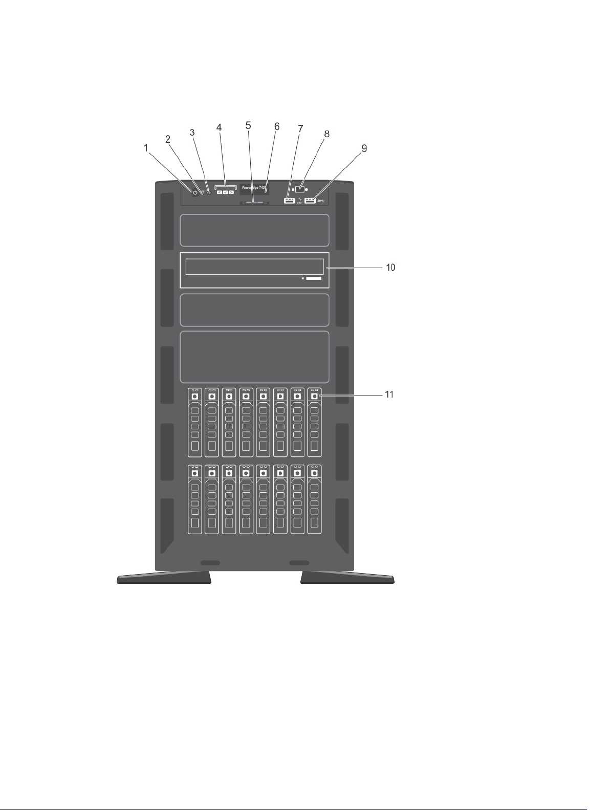
Front-panel features and indicators
Figure 1. Front-panel features and indicators— 2.5 inch hot-swap hard-drive chassis
10
Page 11
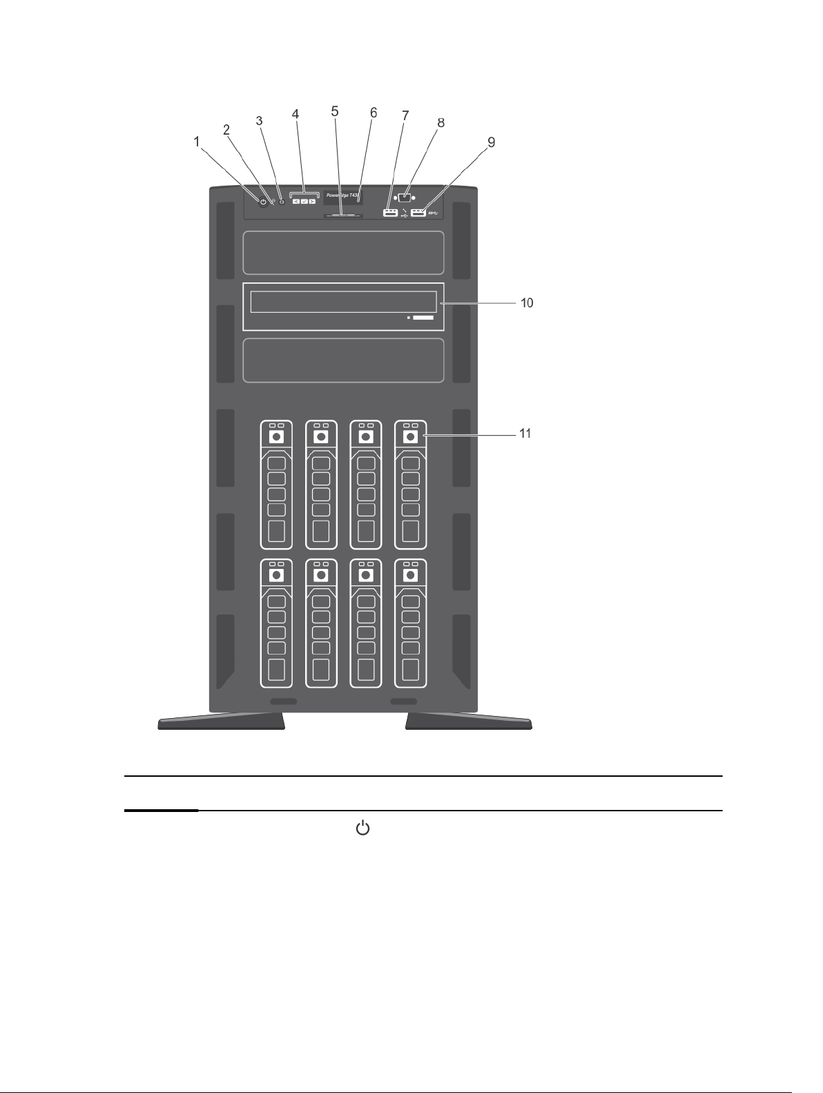
Figure 2. Front-panel features and indicators— 3.5 inch hot-swap hard-drive chassis
Item Indicator, button, or
connector
1
Power-on indicator,
power button
Icon Description
The power-on indicator lights when the system
power is on. The power button controls the power
supply output to the system.
11
Page 12

Item Indicator, button, or
connector
Icon Description
NOTE: On ACPI-compliant operating systems,
turning off the system using the power button
causes the system to perform a graceful
shutdown before power to the system is
turned off.
2 NMI button
3 System identification
button
4 LCD menu buttons Allow you to navigate the control panel LCD menu.
5 Information tag A slide-out label panel which contains system
Used to troubleshoot software and device driver
errors when running certain operating systems.
This button can be pressed using the end of a
paper clip.
Use this button only if directed to do so by
qualified support personnel or by the operating
system documentation.
The identification buttons on the front and back
panels can be used to locate a particular system
within a rack. When one of these buttons is
pressed, the LCD panel on the front and the
system status indicator on the back flash until one
of the buttons is pressed again.
Press to toggle the system ID on and off.
If the system stops responding during POST, press
and hold the system ID button for more than five
seconds to enter BIOS progress mode.
To reset iDRAC (if not disabled in <F2> iDRAC
setup) press and hold for more than 15 seconds.
information such as Service Tag, NIC, MAC
address, and so on for your reference.
6 LCD panel Displays system ID, status information, and system
error messages. See LCD panel features.
NOTE: The LCD panel is not available in a
cabled hard-drive system.
7 USB management port/
iDRAC Direct port
8 Video connector Allows you to connect a display to the system.
12
The USB management port can function as a
regular USB port or provide access to the iDRAC
Direct features. For more information, see the
iDRAC Guide at dell.com/esmmanuals.
This port is USB 2.0-compliant
Page 13

Item Indicator, button, or
connector
9 USB connector Allows you to connect USB devices to the system.
Icon Description
NOTE: The video connector is available only
in the rack-mode configuration of your
system. For information on converting your
system from tower to the rack mode, see
Preparing a system for conversion from tower
mode to rack mode.
This port is USB 3.0-compliant.
10 Optical drive or tape-
drive bay
11 Physical drives 3.5 inch hard drives and 2.5 inch hard drives/SSDs.
Allows you to install optical drives or tape drives.
For more information on supported optical drives
and tape drives, see Optical drives and tape drives
(optional).
13
Page 14
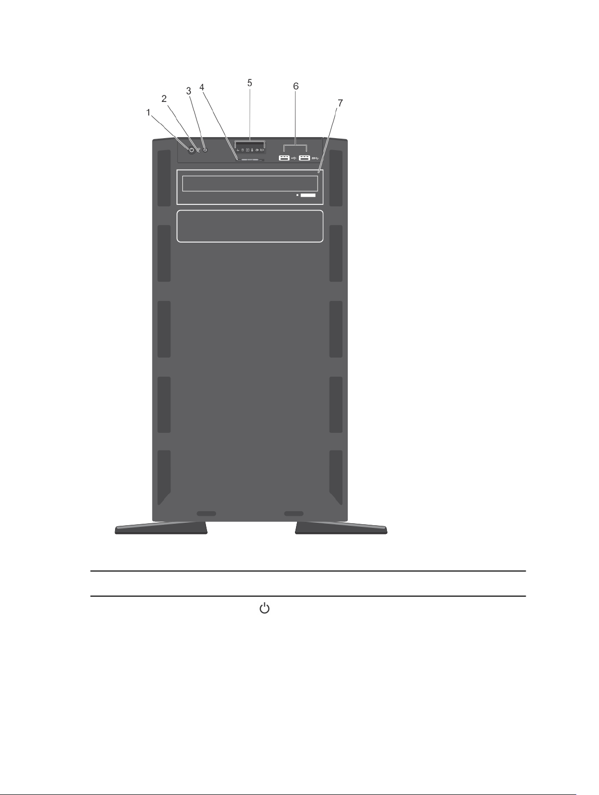
Figure 3. Front-panel features and indicators— 3.5 inch cabled hard-drive chassis
Item Indicator, Button, or
Connector
1 Power-on indicator,
power button
14
Icon Description
The power-on indicator lights when the system
power is on. The power button controls the power
supply output to the system.
Page 15

Item Indicator, Button, or
Connector
Icon Description
NOTE: On ACPI-compliant operating systems,
turning off the system using the power button
causes the system to perform a graceful
shutdown before power to the system is
turned off.
2 NMI button
3 System identification
button
4 Information tag A slide-out label panel which contains system
Used to troubleshoot software and device driver
errors when running certain operating systems.
This button can be pressed using the end of a
paper clip.
Use this button only if directed to do so by
qualified support personnel or by the operating
system documentation.
The identification buttons on the front and back
panels can be used to locate a particular system
within a rack. When one of these buttons is
pressed, the LCD panel on the front and the
system status indicator on the back flash until one
of the buttons is pressed again.
Press to toggle the system ID on and off.
If the system stops responding during POST, press
and hold the system ID button for more than five
seconds to enter BIOS progress mode.
To reset iDRAC (if not disabled in <F2> iDRAC
setup) press and hold for more than 15 seconds.
information such as Service Tag, NIC, MAC
address, and so on for your reference.
5 Diagnostic indicators The diagnostic indicators on the system front
panel display error status during system startup.
For more information, see Diagnostic indicators.
6 USB connectors Allows you to connect USB devices to the system.
One port is USB 2.0-compliant and one port is USB
3.0-compliant.
7 Optical drive or tape-
drive bay
Allows you to install optical drives or tape drives.
For more information on supported optical drives
and tape drives, see Optical drives and tape drives
(optional).
15
Page 16
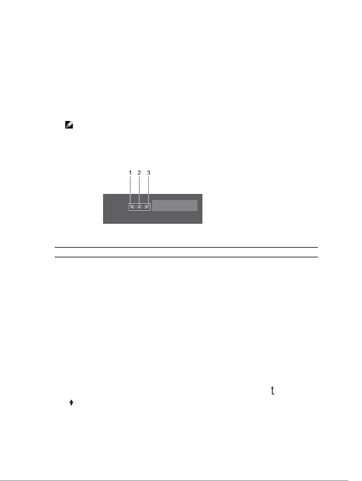
LCD panel features
The system's LCD panel provides system information and status and error messages to indicate if the
system is operating correctly or if the system needs attention. For more information on error messages,
see the Dell Event and Error Messages Reference Guide at dell.com/esmmanuals.
• The LCD backlight lights blue during normal operating conditions.
• When the system needs attention, the LCD lights amber, and displays an error code followed by
descriptive text.
NOTE: If the system is connected to a power source and an error is detected, the LCD lights
amber regardless of whether the system is turned on or off.
• The LCD backlight turns OFF when the system is in standby mode and can be turned on by pressing
either the Select, Left, or Right button on the LCD panel.
• The LCD backlight remains OFF if LCD messaging is turned off through the iDRAC utility, the LCD
panel, or other tools.
Figure 4. LCD panel features
Item Button Description
1 Left Moves the cursor back in one-step increments.
2 Select Selects the menu item highlighted by the cursor.
3 Right Moves the cursor forward in one-step increments.
During message scrolling:
• Press once to increase scrolling speed
• Press again to stop
• Press again to return to the default scrolling speed
• Press again to repeat the cycle
Home screen
The Home screen displays user-configurable information about the system. This screen is displayed
during normal system operation when there are no status messages or errors. When the system is in
standby mode, the LCD backlight turns off after five minutes of inactivity if there are no error messages.
Press one of the three navigation buttons (Select, Left, or Right) to view the Home screen.
To navigate to the Home screen from another menu, continue to select the up arrow until the Home
icon is displayed, and then select the Home icon.
16
Page 17

From the Home screen, press the Select button to enter the main menu.
Setup menu
NOTE: When you select an option in the Setup menu, you must confirm the option before
proceeding to the next action.
Option Description
iDRAC Select DHCP or Static IP to configure the network mode. If Static IP is selected,
the available fields are IP, Subnet (Sub), and Gateway (Gtw). Select Setup DNS to
enable DNS and to view domain addresses. Two separate DNS entries are available.
Set error Select SEL to display LCD error messages in a format that matches the IPMI
description in the SEL. This is useful when trying to match an LCD message with an
SEL entry.
Select Simple to display LCD error messages in a simplified user-friendly
description. See the Dell Event and Error Messages Reference Guide at dell.com/
esmmanuals for the list of messages in this format.
Set home Select the default information to be displayed on the LCD Home screen. See View
Menu to see the options and option items that can be set as the default on the
Home screen.
View menu
NOTE: When you select an option in the View menu, you must confirm the option before
proceeding to the next action.
Option Description
iDRAC IP Displays the IPv4 or IPv6 addresses for the iDRAC7. Addresses include DNS
(Primary and Secondary), Gateway, IP, and Subnet (IPv6 does not have Subnet).
MAC Displays the MAC addresses for iDRAC, iSCSI, or Network devices.
Name Displays the name of the Host, Model, or User String for the system
Number Displays the Asset tag or the Service tag for the system.
Power Displays the power output of the system in BTU/hr or Watts. The display format can
be configured in the Set home submenu of the Setup menu.
Temperature Displays the temperature of the system in Celsius or Fahrenheit. The display format
can be configured in the Set home submenu of the Setup menu.
Diagnostic indicators
The diagnostic indicators on the system front panel display error status during system startup.
NOTE: No diagnostic indicators are lit when the system is switched off. To start the system, plug it
into a working power source and press the power button.
17
Page 18
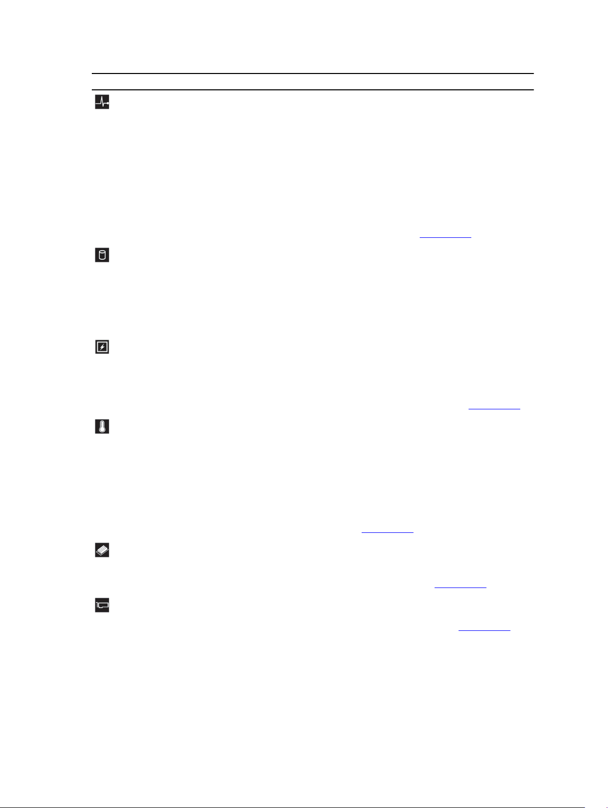
Icon Description Condition Corrective action
Health
indicator
If the system is on, and in
good health, the indicator
lights solid blue.
None required.
Hard-drive
indicator
Electrical
indicator
Temperatur
e indicator
The indicator blinks amber if
the system is on or in
standby, and if any error
exists (for example, a failed
fan or hard drive).
The indicator blinks amber if
a hard drive experiences an
error.
The indicator blinks amber if
the system experiences an
electrical error (for example,
voltage out of range, or a
failed power supply or
voltage regulator).
The indicator blinks amber if
the system experiences a
thermal error (for example, a
temperature out of range or
fan failure).
See the System Event Log or system
messages for the specific issue. For more
information on error messages, see the Dell
Event and Error Messages Reference Guide
at dell.com/esmmanuals.
Invalid memory configurations can cause
the system to halt at startup without any
video output. See Getting help.
See the System Event Log to determine the
hard drive that has an error. Run the
appropriate Online Diagnostics test. Restart
system and run embedded diagnostics
(ePSA). If the hard drives are configured in a
RAID array, restart the system and enter the
host adapter configuration utility program.
See the System Event Log or system
messages for the specific issue. If it is due to
a problem with the power supply, check the
LED on the power supply. Re-seat the
power supply by removing and reinstalling
it. If the problem persists, see Getting help.
Ensure that none of the following
conditions exist:
• A cooling fan is removed or has failed.
• System cover, cooling shroud, EMI filler
panel, memory-module blank, or backfiller bracket is removed.
• Ambient temperature is too high.
• External airflow is obstructed.
18
Memory
indicator
PCIe
indicator
The indicator blinks amber if
a memory error occurs.
The indicator blinks amber if
a PCIe card experiences an
error.
See Getting help.
See the system event log or system
messages for the location of the failed
memory. Reinstall the memory device. If the
problem persists, see Getting help.
Restart the system. Update any required
drivers for the PCIe card. Re-install the card.
If the problem persists, see Getting help.
Page 19
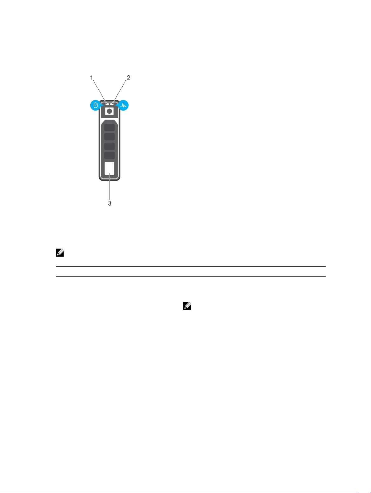
Hard-drive indicator codes
Figure 5. Hard-drive indicators
1. hard-drive activity indicator 2. hard-drive status indicator
3. hard drive
NOTE: If the hard drive is in Advanced Host Controller Interface (AHCI) mode, the status indicator
(on the right side) does not function and remains off.
Drive-status indicator pattern (RAID only) Condition
Blinks green two times per second Identifying drive or preparing for removal.
Off Drive ready for insertion or removal.
NOTE: The drive status indicator remains off until
all hard drives are initialized after the system is
turned on. Drives are not ready for insertion or
removal during this time.
Blinks green, amber, and turns off Predicted drive failure
Blinks amber four times per second Drive failed
Blinks green slowly Drive rebuilding
Steady green Drive online
Blinks green three seconds, amber three
seconds, and turns off six seconds
Rebuild aborted
19
Page 20
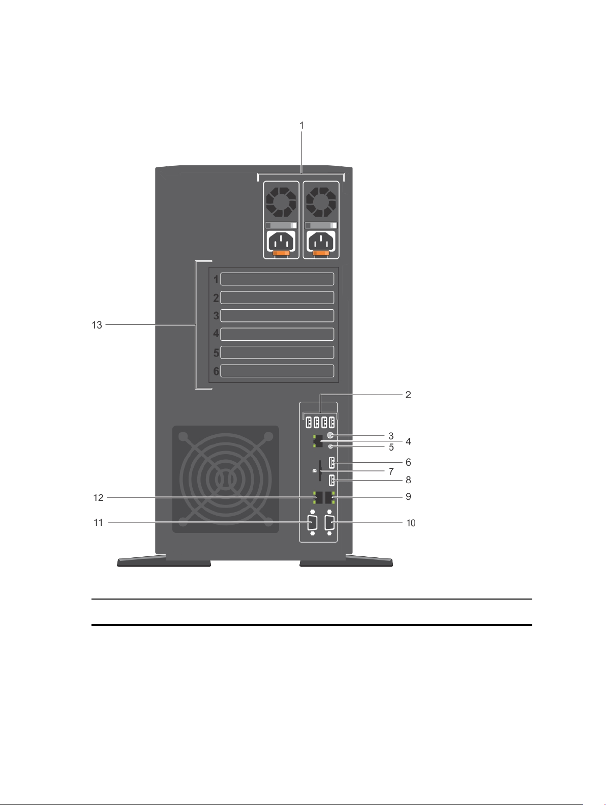
Back-panel features and indicators
Figure 6. Back-panel features and indicators
Item Indicator, button, or
connector
1 Power supplies (PSU1 and
PSU2)
20
Icon Description
Redundant
power supply
Up to two 495 W, 750 W, or
1100 W redundant AC
power supplies.
Page 21
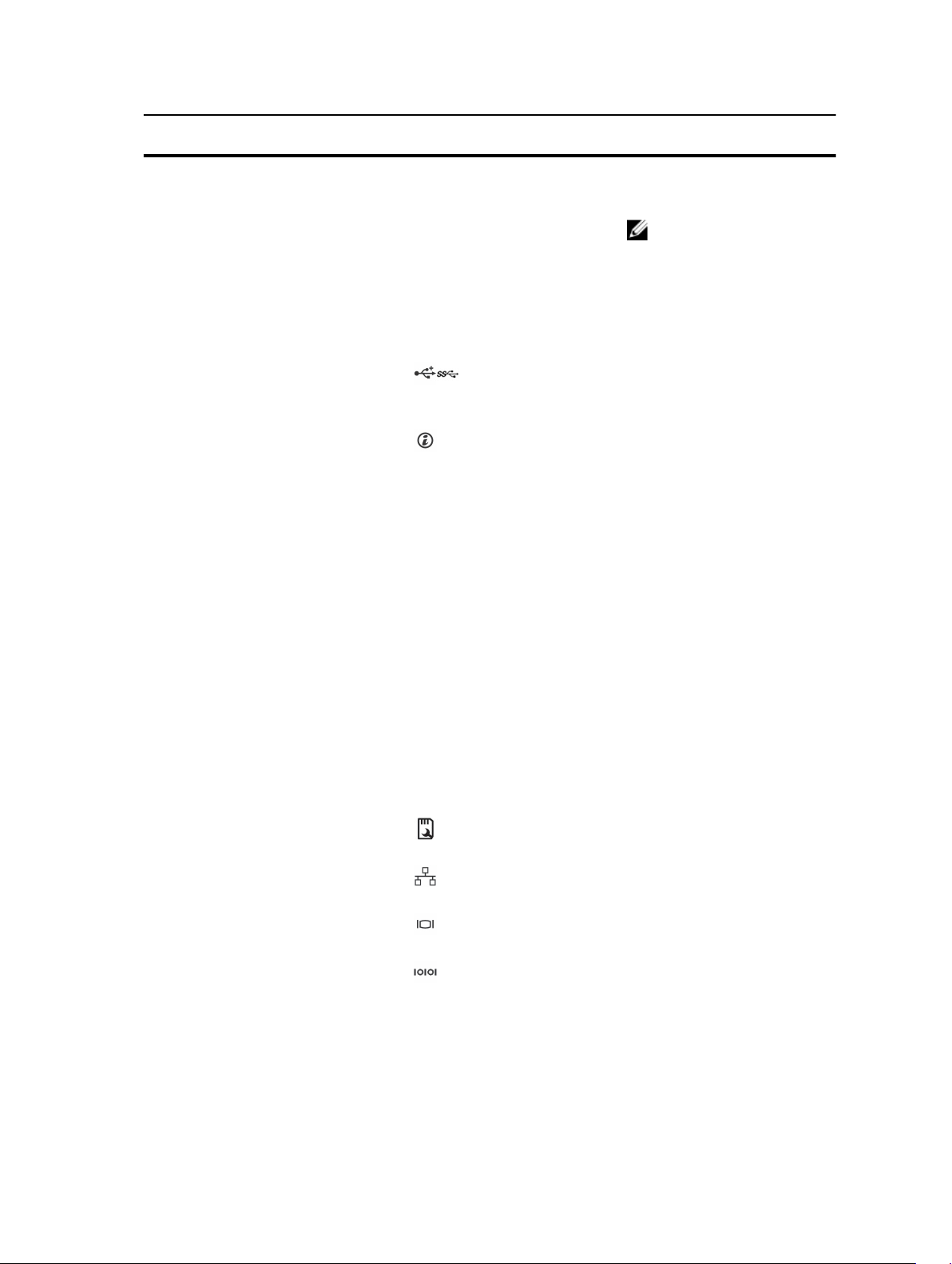
Item Indicator, button, or
connector
Icon Description
Non-redundant
power supply
2, 6, 8 USB connectors (6) Allows you to connect USB devices to the system.
Five ports are USB 2.0-compliant and one port is
USB 3.0-compliant.
3 System identification
button
The identification buttons on the front and back
panels can be used to locate a particular system
within a rack. When one of these buttons is
pressed, the LCD panel on the front and the
system status indicator on the back flash until one
of the buttons is pressed again.
Press to toggle the system ID on and off.
If the system stops responding during POST, press
and hold the system ID button for more than five
seconds to enter the BIOS progress mode.
One 450 W non-redundant
AC power supply.
NOTE: Non-redundant
power supply is
supported in systems
with cabled hard drives
and systems with an x8
backplane.
To reset iDRAC (if not disabled in F2 iDRAC setup),
press and hold for more than 15 seconds.
4 iDRAC port (optional)
5 System identification
connector
7 vFlash media card slot
(optional)
9, 12 Ethernet connectors (2) Two integrated 10/100/1000 Mbps NIC
10 Video connector Allows you to connect a VGA display to the
11 Serial connector Allows you to connect a serial device to the
13 PCIe expansion card slots
(6)
Dedicated management port on the iDRAC ports
card.
Allows you to connect the optional system status
indicator assembly through the optional cable
management arm.
Allows you to insert a vFlash media card.
connectors.
system.
system.
Allows you to connect up to six full-height PCI
expansion cards.
21
Page 22
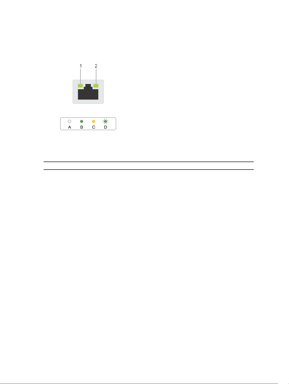
NIC indicator codes
Figure 7. NIC indicators
1. link indicator 2. activity indicator
Convention Indicator pattern Description
A Link and activity indicators
are OFF
B Link indicator is green The NIC is connected to a valid network at its maximum
C Link indicator is yellow The NIC is connected to a valid network at less than its
D Activity indicator is blinking
green
The NIC is not connected to the network.
port speed (1 Gbps).
maximum port speed.
Network data is being sent or received.
Indicator codes for redundant power supply
Each AC power supply has an illuminated translucent handle that indicates whether power is present or
whether a power fault has occurred.
22
Page 23
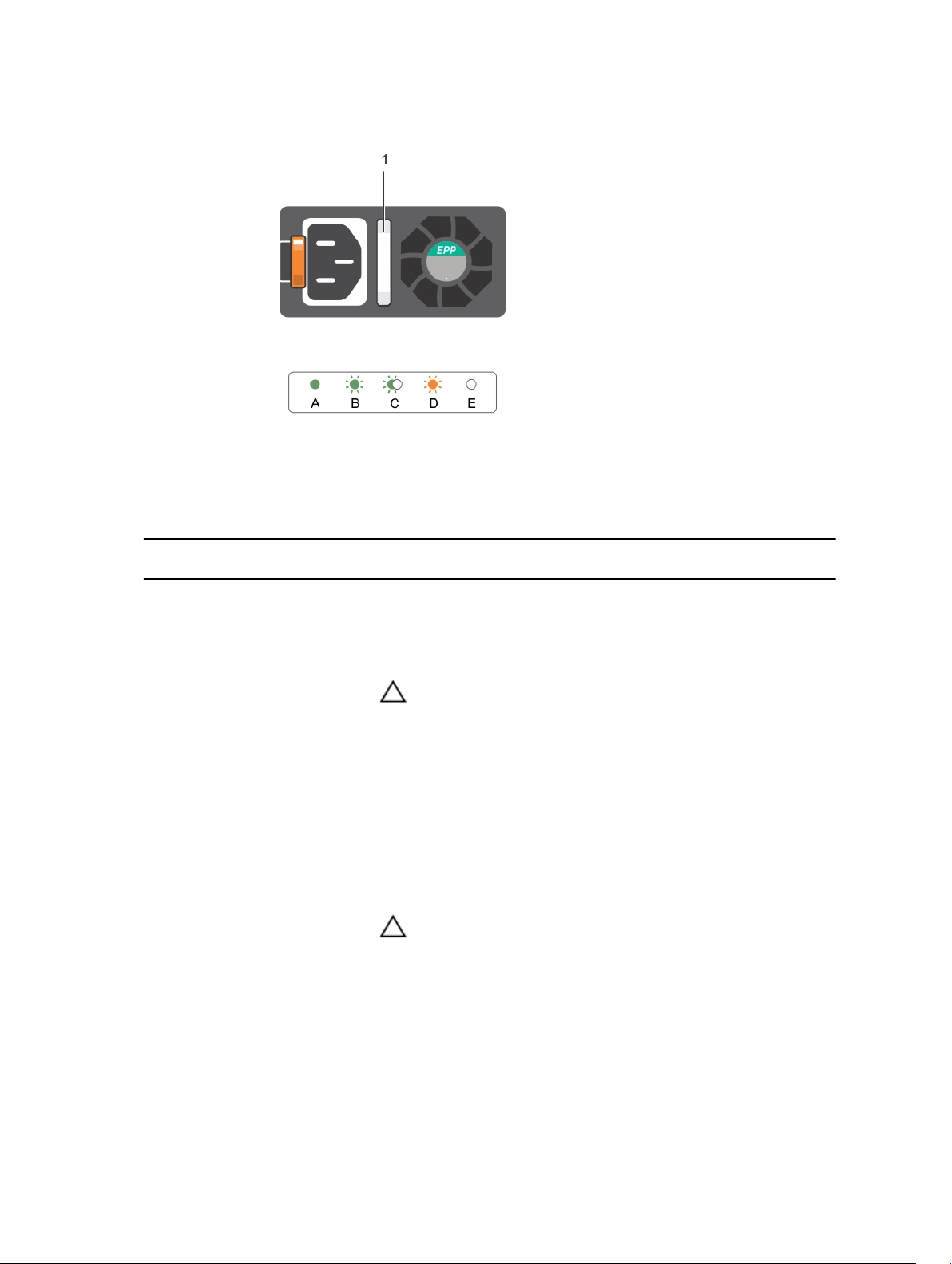
Figure 8. AC power supply status indicator
1. AC power supply status indicator/handle
Convention Power Indicator
Description
Pattern
A Green A valid power source is connected to the power supply and the
power supply is operational.
B Flashing green When the firmware of the power supply unit is being updated, the
power supply handle flashes green.
CAUTION: Do not disconnect the power cord or unplug the
power supply unit when updating firmware. If firmware
update is interrupted, the power supply units will not
function. You must roll back the power supply firmware by
using Life cycle controller. See Dell Lifecycle Controller User’s
Guide at dell.com/esmmanuals.
C Flashing green
and turns off
When hot-adding a power supply unit, the power supply handle
flashes green five times at 4 Hz rate and turns off. This indicates that
there is a power supply mismatch with respect to efficiency, feature
set, health status, and supported voltage. Replace the power supply
with a power supply that matches the capacity of the power supply.
CAUTION: For AC power supplies, use only PSUs with the
Extended Power Performance (EPP) label on the back. Mixing
PSUs from previous generations of PowerEdge servers can
result in a PSU mismatch condition or failure to power on.
D Flashing amber Indicates a problem with the power supply unit.
23
Page 24
Convention Power Indicator
Pattern
E Not lit Power is not connected.
Description
CAUTION: When correcting a power supply mismatch, replace
only the power supply with the flashing indicator. Swapping
the other power supply to make a matched pair can result in
an error condition and unexpected system shutdown. To
change from a High Output configuration to a Low Output
configuration or vice versa, you must power down the system.
CAUTION: AC power supplies support both 220 V and 110 V
input voltages with the exception of Titanium power supplies,
which support only 220 V. When two identical power supplies
receive different input voltages, they can output different
wattages, and trigger a mismatch.
CAUTION: If two power supplies are used, they must be of the
same type and have the same maximum output power.
CAUTION: Combining AC and DC power supplies is not
supported and triggers a mismatch.
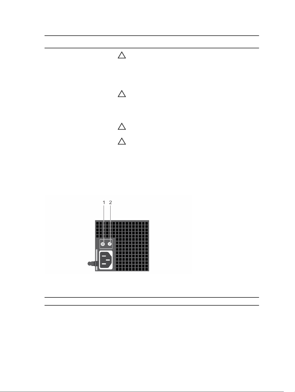
Indicator codes for non-redundant power supply
Press the self-diagnostic button to perform a quick health check on the non-redundant power supply of
the system.
Figure 9. Non-redundant AC power supply status indicator and self-diagnostic button
1. self-diagnostic button 2. AC power supply status indicator
Diagnostic Indicator Pattern Description
Not lit Power is not connected or power supply is faulty.
Green A valid power source is connected to the power supply and
the power supply is operational.
24
Page 25

Documentation matrix
The documentation matrix provides information on documents that you can refer to for setting up and
managing your system.
To... Refer to...
Install your system into a rack Rack documentation included with your rack
solution
Set up your system and know the system technical
specifications
Install the operating system Operating system documentation at dell.com/
Get an overview of the Dell Systems Management
offerings
Configure and log in to iDRAC, set up managed
and management system, know the iDRAC
features and troubleshoot using iDRAC
Know about the RACADM subcommands and
supported RACADM interfaces
Launch, enable and disable Lifecycle Controller,
know the features, use and troubleshoot Lifecycle
Controller
Use Lifecycle Controller Remote Services Dell Lifecycle Controller Remote Services Quick
Set up, use, and troubleshoot OpenManage Server
Administrator
Install, use and troubleshoot OpenManage
Essentials
Getting Started With Your System that shipped with
your system or see dell.com/poweredgemanuals
operatingsystemmanuals
Dell OpenManage Systems Management Overview
Guide at dell.com/openmanagemanuals
Integrated Dell Remote Access Controller User's
Guide at dell.com/esmmanuals
RACADM Command Line Reference Guide for
iDRAC and CMC at dell.com/esmmanuals
Dell Lifecycle Controller User’s Guide at dell.com/
esmmanuals
Start Guide at dell.com/esmmanuals
Dell OpenManage Server Administrator User’s
Guide at dell.com/openmanagemanuals
Dell OpenManage Essentials User’s Guide at
dell.com/openmanagemanuals
Know the features of the storage controller cards,
deploy the cards, and manage the storage
subsystem
Check the event and error messages generated by
the system firmware and agents that monitor
system components
Storage controller documentation at dell.com/
storagecontrollermanuals
Dell Event and Error Messages Reference Guide at
dell.com/esmmanuals
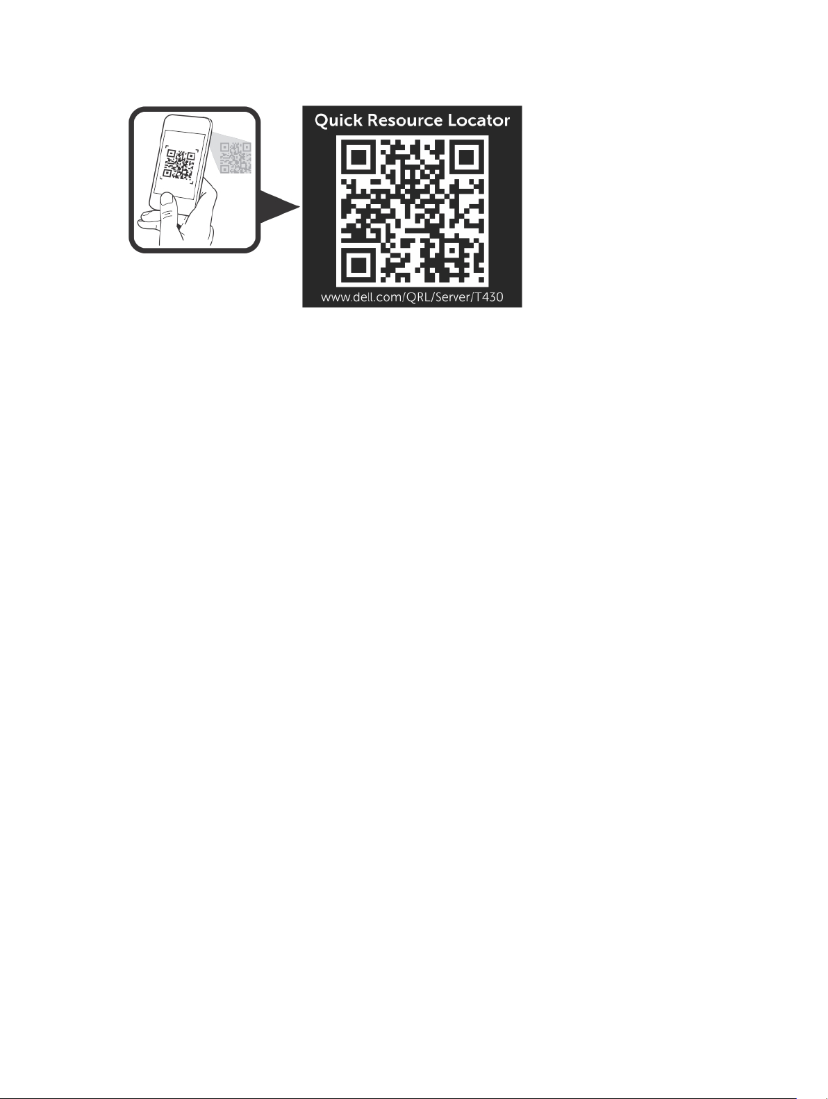
Quick Resource Locator
Use the Quick Resource Locator (QRL) to get immediate access to system information and how-to
videos. This can be done by visiting dell.com/QRL or by using your smartphone or tablet and a model
specific Quick Resource (QR) code located on your Dell PowerEdge system. To try out the QR code, scan
the following image.
25
Page 26
26
Page 27

2
Performing initial system configuration
After you receive your PowerEdge system, you must set up your system, install the operating system if it
is not pre-installed, and set up and configure the system iDRAC IP address.
Setting up your system
1. Unpack the server.
2. Install the server into the rack. For more information on installing the server into the rack, see your
system Rack Installation Placemat at dell.com/poweredgemanuals. For tower systems that can be
converted to the rack mode, see
to know how to convert the tower system to the rack mode configuration.
3. Connect the peripherals to the system.
4. Connect the system to its electrical outlet.
5. Turn the system on by pressing the power button or using iDRAC.
6. Turn on the attached peripherals.
Setting up and configuring the iDRAC IP address
You can set up the Integrated Dell Remote Access Controller (iDRAC) IP address by using one of the
following interfaces:
Preparing a system for conversion from tower mode to rack mode
• iDRAC Settings utility
• Lifecycle Controller
• Dell OpenManage Deployment Toolkit
• Server LCD panel
You can configure iDRAC IP address by using the following interfaces:
• iDRAC Web interface. For more information, see the Integrated Dell Remote Access Controller User's
Guide.
• Remote Access Controller ADMin (RACADM). For more information, see the RACADM Command Line
Interface Reference Guide and the Integrated Dell Remote Access Controller User's Guide.
• Remote Services that includes Web Services Management (WS-Man). For more information, see the
Lifecycle Controller Remote Services Quick Start Guide.
For more information on setting up and configuring iDRAC, see the Integrated Dell Remote Access
Controller User's Guide at dell.com/esmmanuals.
Logging in to iDRAC
You can log in to iDRAC as an iDRAC local user, a Microsoft Active Directory user, or a Lightweight
Directory Access Protocol (LDAP) user. You can also log in by using Single Sign-On or a Smart Card. The
27
Page 28

default user name is root and password is calvin. For more information on logging in to iDRAC and
iDRAC licenses, see the Integrated Dell Remote Access Controller User's Guide at dell.com/esmmanuals.
You can also access iDRAC using RACADM. For more information, see the RACADM Command Line
Interface Reference Guide and the Integrated Dell Remote Access Controller User's Guide available at
dell.com/esmmanuals.
Installing the operating system
If the server is shipped without an operating system, install the supported operating system on the server
by using one of the following methods:
• Dell Systems Management Tools and Documentation media. See the operating system
documentation at dell.com/operatingsystemmanuals.
• Dell Lifecycle Controller. See the Lifecycle Controller documentation at dell.com/esmmanuals.
• Dell OpenManage Deployment Toolkit. See the OpenManage documentation at dell.com/
openmanagemanuals.
For information on the list of operating systems supported on your system, see the operating systems
support matrix at dell.com/ossupport.
Managing your system remotely
To perform out-of-band systems management using iDRAC, you must configure iDRAC for remote
accessibility, set up the management station and managed system, and configure the supported Web
browsers. For more information, see the Integrated Dell Remote Access Controller User’s Guide at
dell.com/esmmanuals.
You can also remotely monitor and manage the server by using the Dell OpenManage Server
Administrator (OMSA) software and OpenManage Essentials (OME) systems management console. For
more information, see dell.com/openmanagemanuals.
Downloading and installing drivers and firmware
It is recommended that you download and install the latest BIOS, drivers, and systems management
firmware on your system.
Prerequisites
Ensure that you clear the web browser cache.
Steps
1. Go to dell.com/support/drivers.
2. In the Product Selection section, enter the Service Tag of your system in the Service Tag or Express
Service Code field.
NOTE: If you do not have the Service Tag, select Automatically detect my Service Tag for me
to allow the system to automatically detect your Service Tag, or select Choose from a list of all
Dell products to select your product from the Product Selection page.
3. Click Get drivers and downloads.
The drivers that are applicable to your selection are displayed.
28
Page 29

4. Download the drivers you require to a diskette drive, USB drive, CD, or DVD.
29
Page 30

Pre-operating system management applications
The pre-operating system management applications for your PowerEdge system help you manage
different settings and features of your system without booting to the operating system.
Your PowerEdge system has the following pre-operating system management applications:
• System Setup
• Boot Manager
• Dell Lifecycle Controller
Navigation keys
The navigation keys can help you access the pre-operating system management applications.
Key Description
<Page Up> Moves to the previous screen.
3
<Page
Down>
Up arrow Moves to the previous field.
Down
arrow
<Enter> Enables you to type a value in the selected field (if applicable) or follow the link in the field.
Spacebar Expands or collapses a drop-down list, if applicable.
<Tab> Moves to the next focus area.
<Esc> Moves to the previous page until you view the main screen. Pressing <Esc> in the main
<F1> Displays the System Setup help.
Moves to the next screen.
Moves to the next field.
NOTE: This feature is applicable for the standard graphical browser only.
screen exits System BIOS/iDRAC Settings/Device Settings/Service Tag Settings and
proceeds with system boot.
About System Setup
Using System Setup, you can configure the BIOS settings, iDRAC settings, and device settings of your
system.
You can access System Setup in two ways:
30
Page 31

• Standard Graphical Browser — This is enabled by default.
• Text Browser — This is enabled using Console Redirection.
NOTE: By default, help text for the selected field is displayed in the graphical browser. To view the
help text in the text browser, press <F1>.
Entering System Setup
1. Turn on or restart your system.
2. Press <F2> immediately after you see the following message:
<F2> = System Setup
If your operating system begins to load before you press <F2>, allow the system to finish booting,
and then restart your system and try again.
System Setup Main Menu
Option Description
System BIOS Enables you to configure BIOS settings.
iDRAC Settings Enables you to configure iDRAC settings.
The iDRAC Settings utility is an interface to set up and configure the
iDRAC parameters by using UEFI. You can enable or disable various
iDRAC parameters by using the iDRAC Settings utility. For more
information about this utility, see the Integrated Dell Remote Access
Controller User’s Guide at dell.com/esmmanuals.
Device Settings Enables you to configure device settings.
System BIOS screen
By using the System BIOS screen you can view the BIOS settings as well as edit specific functions such as
Boot Order, System Password, Setup Password, setting the RAID mode, and enabling or disabling USB
ports.
In the System Setup Main Menu, click System BIOS.
Menu Item Description
System Information Displays information about the system such as the system model name,
BIOS version and Service Tag.
Memory Settings Displays information and options related to the installed memory.
Processor Settings Displays information and options related to the processor such as speed,
cache size, and so on.
SATA Settings Displays options to enable or disable the integrated SATA controller and
ports.
Boot Settings Displays options to specify the boot mode (BIOS or UEFI). Enables you to
modify UEFI and BIOS boot settings.
Network Settings Displays options to change the network settings.
Integrated Devices Displays options to enable or disable integrated device controllers and
ports, and to specify related features and options.
31
Page 32

Menu Item Description
Serial Communication Displays options to enable or disable the serial ports and specify related
features and options.
System Profile Settings Displays options to change the processor power management settings,
memory frequency, and so on.
System Security Displays options to configure the system security settings like, system
password, setup password, TPM security, and so on. It also enables or
disables support for the power and NMI buttons on the system.
Miscellaneous Settings Displays options to change the system date, time, and so on.
System Information screen
You can use the System Information screen to view system properties such as Service Tag, system
model, and the BIOS version.
To view the System Information click System Setup Main Menu → System BIOS → System Information.
Menu Item Description
System Model Name Displays the system model name.
System BIOS Version Displays the BIOS version installed on the system.
System Management
Engine Version
System Service Tag Displays the system Service Tag.
System Manufacturer Displays the name of the system manufacturer.
System Manufacturer
Contact Information
System CPLD Version Displays the current revision of the system CPLD firmware.
UEFI Compliance Version Displays the system firmware UEFI compliance level.
Displays the current revision of the Management Engine firmware.
Displays the contact information of the system manufacturer.
Memory Settings screen
You can use the Memory Settings screen to view all the memory settings as well as enable or disable
specific memory functions such as system memory testing and node interleaving.
To view theMemory Setting screen, click System Setup Main Menu → System BIOS → Memory Settings.
Menu Item Description
System Memory Size Displays the amount of memory installed in the system.
System Memory Type Displays the type of memory installed in the system.
System Memory Speed Displays the system memory speed.
System Memory Voltage Displays the system memory voltage.
Video Memory Displays the amount of video memory utilized.
System Memory Testing Specifies whether system memory tests are run during system boot.
Options are Enabled and Disabled. By default, the System Memory
Testing option is set to Disabled.
Memory Operating Mode Specifies the memory operating mode. The options available are
Optimizer Mode, Advanced ECC Mode, Mirror Mode, Spare Mode, and
32
Page 33

Menu Item Description
Spare with Advanced ECC Mode. By default, the Memory Operating
Mode option is set to Optimizer Mode.
NOTE: The Memory Operating Mode can have different defaults
and available options based on the memory configuration of your
system.
Node Interleaving Specifies if Non-Uniform Memory architecture (NUMA) is supported. If
this field is Enabled, memory interleaving is supported if a symmetric
memory configuration is installed. If Disabled, the system supports
NUMA (asymmetric) memory configurations. By default, Node
Interleaving
Snoop Mode Specifies the Snoop Mode options. Snoop Mode options available are
Home Snoop, Early Snoop, and Cluster on Die. By default, the Snoop
Mode option is set to Early Snoop. The field is only available when Node
Interleaving is Disabled.
option is set to Disabled.
Processor Settings screen
You can use the Processor Settings screen to view the processor settings and perform specific functions
such as enabling virtualization technology, hardware prefetcher, and logical processor idling.
To view the Processor Settings screen, click System Setup Main Menu → System BIOS → Processor
Settings.
Menu Item Description
Logical Processor Enables or disables the logical processors and displays the number of
logical processors. If the Logical Processor option is set to Enabled, the
BIOS displays all the logical processors. If this option is set to Disabled,
the BIOS displays only one logical processor per core. By default, the
Logical Processor option is set to Enabled.
Alternate RTID (Requestor
Transaction ID) Setting
Virtualization Technology Enables or disables the additional hardware capabilities provided for
Address Translation Service
(ATS)
Adjacent Cache Line
Prefetch
Hardware Prefetcher Enables or disables the hardware prefetcher. By default, the Hardware
DCU Streamer Prefetcher Allows you to enable or disable the Data Cache Unit (DCU) streamer
Enables you to allocate more RTIDs to the remote socket, thereby
increasing cache performance between the sockets or easing work in
normal mode for NUMA. By default, the Alternate RTID (Requestor
Transaction ID) Setting is set to Disabled.
virtualization. By default, the Virtualization Technology option is set to
Enabled.
Defines the Address Translation Cache (ATC) for devices to cache the
DMA transactions. This field provides an interface to a chipset's Address
Translation and Protection Table to translate DMA addresses to host
addresses. By default, the option is set to Enabled.
Optimizes the system for applications that require high utilization of
sequential memory access. By default, the Adjacent Cache Line Prefetch
option is set to Enabled. You can disable this option for applications that
require high utilization of random memory access.
Prefetcher option is set to Enabled.
prefetcher. By default, the DCU Streamer Prefetcher option is set to
Enabled.
33
Page 34

Menu Item Description
DCU IP Prefetcher Enables or disables the Data Cache Unit (DCU) IP prefetcher. By default,
the DCU IP Prefetcher option is set to Enabled.
Execute Disable Enables or disables the execute disable memory protection technology.
By default, the Execute Disable option is set to Enabled.
Logical Processor Idling Enables or disables the operating system capability to put logical
processors in the idling state in order to reduce power consumption. By
default, the option is set to Disabled.
Configurable TDP Allows reconfiguration of Thermal Design Power (TDP) to lower levels.
TDP refers to the maximum amount of power the cooling system is
required to dissipate.
X2Apic Mode Enables or disables the X2Apic mode.
Number of Cores per
Processor
Processor 64-bit Support Specifies if the processor(s) support 64-bit extensions.
Processor Core Speed Displays the maximum core frequency of the processor.
Processor Bus Speed Displays the bus speed of the processor.
Controls the number of enabled cores in each processor. By default, the
Number of Cores per Processor option is set to All.
NOTE: The processor bus speed option displays only when both
processors are installed.
Processor 1
Family-Model-Stepping Displays the family, model and stepping of the processor as defined by
Brand Displays the brand name reported by the processor.
Level 2 Cache Displays the total L2 cache.
Level 3 Cache Displays the total L3 cache.
Number of Cores Displays the number of cores per processor.
NOTE: Depending on the number of installed CPUs, there may be
up to two processor listings. The following settings are displayed for
each processor installed in the system.
Intel.
SATA Settings screen
You can use the SATA Settings screen to view the SATA settings of SATA devices and enable RAID on
your system.
To view the SATA Settings screen click System Setup Main Menu → System BIOS → SATA Settings.
Menu Item Description
Embedded SATA Enables the embedded SATA to be set to Off, ATA, AHCI, or RAID modes.
By default, the Embedded SATA option is set to AHCI.
Security Freeze Lock Sends Security Freeze Lock command to the Embedded SATA drives
during POST. This option is applicable only to ATA and AHCI mode.
Write Cache Enables or disables the command for Embedded SATA drives during
POST.
34
Page 35

Menu Item Description
Port A Sets the drive type of the selected device. For Embedded SATA settings
in ATA mode, set this field to Auto to enable BIOS support. Set it to OFF
to turn off BIOS support.
For AHCI mode or RAID mode, BIOS always enables support.
Model Displays the drive model of the selected device.
Drive Type Displays the type of drive attached to the SATA port.
Capacity Displays the total capacity of the hard drive. The field is undefined for
removable media devices such as optical drives.
Port B Sets the drive type of the selected device. For Embedded SATA settings
in ATA mode, set this field to Auto to enable BIOS support. Set it to OFF
to turn off BIOS support.
For AHCI mode or RAID mode, BIOS always enables support.
Model Displays the drive model of the selected device.
Drive Type Displays the type of drive attached to the SATA port.
Capacity Displays the total capacity of the hard drive. The field is undefined for
removable media devices such as optical drives.
Port C Sets the drive type of the selected device. For Embedded SATA settings
in ATA mode, set this field to Auto to enable BIOS support. Set it to OFF
to turn off BIOS support.
For AHCI mode or RAID mode, BIOS always enables support.
Model Displays the drive model of the selected device.
Drive Type Displays the type of drive attached to the SATA port.
Capacity Displays the total capacity of the hard drive. The field is undefined for
removable media devices such as optical drives.
Port D Sets the drive type of the selected device. For Embedded SATA settings
in ATA mode, set this field to Auto to enable BIOS support. Set it to OFF
to turn off BIOS support.
For AHCI mode or RAID mode, BIOS always enables support.
Model Displays the drive model of the selected device.
Drive Type Displays the type of drive attached to the SATA port.
Capacity Displays the total capacity of the hard drive. The field is undefined for
removable media devices such as optical drives.
Port E Sets the drive type of the selected device. For Embedded SATA settings
in ATA mode, set this field to Auto to enable BIOS support. Set it to OFF
to turn off BIOS support.
For AHCI mode or RAID mode, BIOS always enables support.
Model Displays the drive model of the selected device.
Drive Type Displays the type of drive attached to the SATA port.
35
Page 36

Menu Item Description
Capacity Displays the total capacity of the hard drive. The field is undefined for
removable media devices such as optical drives.
Port F Sets the drive type of the selected device. For Embedded SATA settings
in ATA mode, set this field to Auto to enable BIOS support. Set it to OFF
to turn off BIOS support.
For AHCI mode or RAID mode, BIOS always enables support.
Model Displays the drive model of the selected device.
Drive Type Displays the type of drive attached to the SATA port.
Capacity Displays the total capacity of the hard drive. The field is undefined for
removable media devices such as optical drives.
Port G Sets the drive type of the selected device. For Embedded SATA settings
in ATA mode, set this field to Auto to enable BIOS support. Set it to OFF
to turn off BIOS support.
For AHCI mode or RAID mode, BIOS always enables support.
Model Displays the drive model of the selected device.
Drive Type Displays the type of drive attached to the SATA port.
Capacity Displays the total capacity of the hard drive. The field is undefined for
removable media devices such as optical drives.
Port H Sets the drive type of the selected device. For Embedded SATA settings
in ATA mode, set this field to Auto to enable BIOS support. Set it to OFF
to turn off BIOS support.
For AHCI mode or RAID mode, BIOS always enables support.
Model Displays the drive model of the selected device.
Drive Type Displays the type of drive attached to the SATA port.
Capacity Displays the total capacity of the hard drive. The field is undefined for
removable media devices such as optical drives.
Port I Sets the drive type of the selected device. For Embedded SATA settings
in ATA mode, set this field to Auto to enable BIOS support. Set it to OFF
to turn off BIOS support.
For AHCI mode or RAID mode, BIOS always enables support.
Model Displays the drive model of the selected device.
Drive Type Displays the type of drive attached to the SATA port.
Capacity Displays the total capacity of the hard drive. The field is undefined for
removable media devices such as optical drives.
Port J Sets the drive type of the selected device. For Embedded SATA settings
in ATA mode, set this field to Auto to enable BIOS support. Set it to OFF
to turn off BIOS support.
For AHCI mode or RAID mode, BIOS always enables support.
Model Displays the drive model of the selected device.
36
Page 37
Menu Item Description
Drive Type Displays the type of drive attached to the SATA port.
Capacity Displays the total capacity of the hard drive. The field is undefined for
removable media devices such as optical drives.
Boot Settings screen
You can use the Boot Settings screen to set the Boot mode to either BIOS or UEFI. It also allows you to
specify the boot order.
To view the Boot Settings screen click System Setup Main Menu → System BIOS → Boot Settings.
Menu Item Description
Boot Mode Enables you to set the boot mode of the system.
CAUTION: Switching the boot mode may prevent the system from
booting if the operating system is not installed in the same boot
mode.
NOTE: Setting this field to UEFI disables the BIOS Boot Settings
menu. Setting this field to BIOS disables the UEFI Boot Settings
menu.
If the operating system supports UEFI, you can set this option to UEFI.
Setting this field to BIOS allows compatibility with non-UEFI operating
systems. By default, the Boot Mode option is set to BIOS.
Boot Sequence Retry Enables or disables the Boot Sequence Retry feature. If this field is
enabled and the system fails to boot, the system reattempts the boot
sequence after 30 seconds. By default, the Boot Sequence Retry option
is set to Enabled.
Hard-Disk Failover Specifies which devices in the Hard-Disk Drive Sequence are attempted
in the boot sequence. When the option is Disabled, only the first hard
disk device in the list is attempted to boot. When set to Enabled, all hard
disk devices are attempted in order, as listed in the Hard-Disk Drive
Sequence
Boot Option Settings Configures the boot sequence and the boot devices.
. This option is not enabled for UEFI Boot Mode.
Network Settings screen
You can use the Network Settings screen to modify PXE device settings. Network Settings are only
available in UEFI boot mode. BIOS does not control network settings in the BIOS boot mode. For BIOS
boot mode, the network settings are handled by the network controllers option ROM.
To view the Network Settings click System Setup Main Menu → System BIOS → Network Settings.
Menu Item Description
PXE Device n (n = 1 to 4) Enables or disables the device. When enabled, a UEFI boot option is
created for the device.
PXE Device n Settings (n = 1
to 4)
Allows you to control the configuration of the PXE device.
37
Page 38

Integrated Devices screen details
Integrated Devices screen allows you to view and configure the settings of all integrated devices
including the video controller, integrated RAID controller, and the USB ports.
In the System Setup Main Menu, click System BIOS → Integrated Devices.
The Integrated Devices screen details are explained below.
Menu Item Description
USB 3.0 Setting Allows you to enable or disable the USB 3.0 support Enable this option
only if your operating system supports USB 3.0. Disabling this allows
devices to operate at USB 2.0 speed. USB 3.0 is disabled by default.
User Accessible USB Ports Allows you to enable or disable the USB ports. Selecting Only Back Ports
On disables the front USB ports, selecting All Ports Off disables all USB
ports. The USB keyboard and mouse operates during boot process in
certain operating systems. After the boot process is complete, the USB
keyboard and mouse does not work if the ports are disabled.
NOTE: Selecting Only Back Ports On and All Ports Off will disable
the USB management port and also restrict access to iDRAC
features.
Internal USB Port Allows you to enable or disable the internal USB port. By default, the
Internal USB Port option is set to Enabled.
Embedded NIC1 and NIC2 Allows you to enable or disable the Embedded NIC1 and NIC2 .If set to
Disabled, the NIC may still be available for shared network access by the
embedded management controller. Configure this function using the
NIC management utilities of the system.
I/OAT DMA Engine Allows you to enable or disable the I/OAT option Enable only if the
hardware and software supports the feature.
Embedded Video Controller Allows you to enable or disable the Embedded Video Controller. By
default, the embedded video controller is Enabled. If the Embedded
Video Controller is the only display capability in the system (that is, no
add-in graphics card is installed), then the Embedded Video Controller is
automatically used as the primary display even if the Embedded Video
Controller setting is
Current State of Embedded
Video Controller
SR-IOV Global Enable Allows you to enable or disable the BIOS configuration of Single Root I/O
OS Watchdog Timer If your system stops responding, this watchdog timer aids in the recovery
Memory Mapped I/O above
4GB
Slot Disablement Allows you to enable or disable available PCIe slots on your system. The
Displays the current state of the Embedded Video Controller. Current
State of Embedded Video Controller is a read only field, indicating the
current state for the Embedded Video Controller.
Virtualization (SR-IOV) devices. By default, the SR-IOV Global Enable
option is set to Disabled.
of your operating system. When this field is set to Enabled, the operating
system is allowed to initialize the timer. When is set to Disabled (the
default), the timer will have no effect on the system.
Allows you to enable support for PCIe devices that require large amounts
of memory. By default, the option is set to Enabled.
Slot Disablement feature controls the configuration of PCIe cards
Disabled.
38
Page 39

Menu Item Description
installed in the specified slot. Slot disablement must be used only when
the installed peripheral card is preventing booting into the operating
system or causing delays in system startup. If the slot is disabled, both the
Option ROM and UEFI driver are disabled.
Serial Communication screen
You can use the Serial Communication screen to view the properties of the serial communication port.
To view the Serial Communication click System Setup Main Menu → System BIOS → Serial
Communication.
Menu Item Description
Serial Communication Selects serial communication devices (Serial Device 1 and Serial Device 2)
in the BIOS. BIOS console redirection can also be enabled and the port
address can be specified. By default, Serial Communication option is set
to Auto.
Serial Port Address Enables you to set the port address for serial devices. By default, the
Serial Port Address option is set to Serial Device 1=COM2, Serial Device
2=COM1
NOTE: You can use only Serial Device 2 for the Serial Over LAN
(SOL) feature. To use console redirection by SOL, configure the
same port address for console redirection and the serial device.
NOTE: Every time the system boots, the BIOS syncs the serial MUX
setting saved in iDRAC. The serial MUX setting can independently be
changed in iDRAC. Therefore, loading the BIOS default settings from
within the BIOS setup utility may not always revert this setting to the
default setting of Serial Device 1.
External Serial Connector You can associate the External Serial Connector to Serial Device 1, Serial
Device 2, or the Remote Access Device using this field.
NOTE: Only Serial Device 2 can be used for (Serial Over LAN) SOL.
To use console redirection by SOL, configure the same port address
for console redirection and the serial device.
NOTE: Every time the system boots, the BIOS syncs the serial MUX
setting saved in iDRAC. The serial MUX setting can independently be
changed in iDRAC. Therefore, loading the BIOS default settings from
within the BIOS setup utility may not always revert this setting to the
default setting of Serial Device 1.
Failsafe Baud Rate Displays the failsafe baud rate for console redirection. The BIOS attempts
to determine the baud rate automatically. This failsafe baud rate is used
only if the attempt fails, and the value must not be changed. By default,
the Failsafe Baud Rate option is set to 115200.
Remote Terminal Type Sets the remote console terminal type. By default, the Remote Terminal
Type option is set to VT 100/VT 220.
Redirection After Boot Enables or disables the BIOS console redirection when the operating
system is loaded. By default, the Redirection After Boot option is set to
Enabled.
39
Page 40

System Profile Settings screen
You can use the System Profile Settings screen to enable specific system performance settings such as
power management.
To view the System Profile Settings click System Setup Main Menu → System BIOS → System Profile
Settings.
Menu Item Description
System Profile Sets the system profile. If you set the System Profile option to a mode
other than Custom, the BIOS automatically sets the rest of the options.
You can only change the rest of the options if the mode is set to Custom.
By default, the System Profile option is set to Performance Per Watt
Optimized (DAPC)
NOTE: The following parameters are available only when the System
Profile is set to Custom.
CPU Power Management Sets the CPU power management. By default, the CPU Power
Management option is set to System DBPM (DAPC). DBPM is Demand-
Based Power Management.
Memory Frequency Sets the speed of the system memory. You can select Maximum
Performance, Maximum Reliability, or a specific speed.
Turbo Boost Enables or disables the processor to operate in turbo boost mode. By
default, the Turbo Boost option is set to Enabled.
Energy Efficient Turbo Enables or disables the Energy Efficient Turbo.
Energy Efficient Turbo (EET) is a mode of operation where a processor’s
core frequency is adjusted within the turbo range based on workload.
. DAPC is Dell Active Power Controller.
C1E Enables or disables the processor to switch to a minimum performance
state when it is idle. By default, the C1E option is set to Enabled.
C States Enables or disables the processor to operate in all available power states.
By default, the C States option is set to Enabled.
Collaborative CPU
Performance Control
Memory Patrol Scrub Sets the memory patrol scrub frequency. By default, the Memory Patrol
Memory Refresh Rate Sets the memory refresh rate to either 1x or 2x. By default, the Memory
Uncore Frequency Selects the Processor Uncore Frequency.
Energy Efficient Policy Enables you to selects the Energy Efficient Policy.
Enables or disables the CPU power management. When set to Enabled,
the CPU power management is controlled by the OS DBPM and the
System DBPM (DAPC). By default, the option is set to Disabled.
Scrub option is set to Standard.
Refresh Rate option is set to 1x.
Dynamic mode allows the processor to optimize power resources across
the cores and uncore during runtime. The optimization of the uncore
frequency to either save power or optimize performance is influenced by
the setting of the Energy Efficiency Policy.
The CPU uses the setting to manipulate the internal behavior of the
processor and determines whether to target higher performance or
better power savings.
40
Page 41
Menu Item Description
Number of Turbo Boot
Enabled Cores for Processor
1
Monitor/Mwait Enables the Monitor/Mwait instructions in the processor. By default, the
NOTE: If there are two processors installed in the system, you see an
entry for Number of Turbo Boost Enabled Cores for Processor 2.
Controls the number of turbo boost enabled cores for processor 1. By
default, the maximum number of cores is enabled.
Monitor/Mwait option is set to Enabled for all system profiles, except
Custom.
NOTE: This option can be disabled only if the C States option in
Custom mode is disabled.
NOTE: When C States is enabled in Custom mode, changing the
Monitor/Mwait setting does not impact system power/performance.
System Security Settings screen
You can use the System Security screen to perform specific functions such as setting the system
password, setup password and disabling the power button.
To view the System Security click System Setup Main Menu → System BIOS → System Security Settings.
Menu Item Description
Intel AES-NI Improves the speed of applications by performing encryption and
decryption using the Advanced Encryption Standard Instruction Set and is
set to Enabled by default.
System Password Sets the system password. This option is set to Enabled by default and is
read-only if the password jumper is not installed in the system.
Setup Password Sets the setup password. This option is read-only if the password jumper
is not installed in the system.
Password Status Locks the system password. By default, the Password Status option is set
to Unlocked.
TPM Security
TPM Information Changes the operational state of the TPM. By default, the TPM Activation
TPM Status Displays the TPM status.
TPM Command
NOTE: The TPM menu is available only when the TPM module is
installed.
Allows you to control the reporting mode of the Trusted Platform
Module (TPM). By default, the TPM Security option is set to Off. You can
only modify the TPM Status, TPM Activation , and Intel TXT fields if the
TPM Status field is set to either On with Pre-boot Measurements or On
without Pre-boot Measurements.
option is set to No Change.
CAUTION: Clearing the TPM results in the loss of all keys in the
TPM. The loss of TPM keys may affect booting to the operating
system.
Clears all the contents of the TPM. By default, the TPM Clear option is set
to
No.
41
Page 42

Menu Item Description
Intel TXT Enables or disables the Intel Trusted Execution Technology (TXT). To
enable Intel TXT, Virtualization Technology must be enabled and TPM
Security must be Enabled with Pre-boot measurements. By default, the
Intel TXT option is set to Off
Power Button Enables or disables the power button on the front of the system. By
default, the Power Button option is set to Enabled.
NMI Button Enables or disables the NMI button on the front of the system. By default,
the NMI Button option is set to Disabled.
AC Power Recovery Sets how the system reacts after AC power is restored to the system. By
default, the AC Power Recovery option is set to Last.
AC Power Recovery Delay Sets how the system supports staggering of power up after AC power is
restored to the system. By default, the AC Power Recovery Delay option
is set to Immediate.
User Defined Delay (60s to
240s)
UEFI Variable Access Provides varying degrees of securing UEFI variables. When set to
Secure Boot Enables Secure Boot, where the BIOS authenticates each pre-boot image
Secure Boot Policy When Secure Boot policy is Standard, the BIOS uses the system
Secure Boot Policy
Summary
Sets the User Defined Delay when the User Defined option for AC Power
Recovery Delay is selected.
Standard (the default) UEFI variables are accessible in the Operating
System per the UEFI specification. When set to Controlled, selected UEFI
variables are protected in the environment and new UEFI boot entries are
forced to be at the end of the current boot order.
using the certificates in the Secure Boot Policy. Secure Boot is disabled
by default.
manufacturer’s key and certificates to authenticate pre-boot images.
When Secure Boot policy is Custom, the BIOS uses the user-defined key
and certificates. Secure Boot policy is Standard by default.
Displays the list of certificates and hashes that secure boot uses to
authenticate images.
Secure Boot Custom Policy Settings screen
Secure Boot Custom Policy Settings is displayed only when Secure Boot Policy is set to Custom.
In the System Setup Main Menu, click System BIOS → System Security → Secure Boot Custom Policy
Settings
Menu Item Description
Platform Key Imports, exports, deletes, or restores the platform
Key Exchange Key Database Allows you to import, export, delete, or restore
Authorized Signature Database Imports, exports, deletes, or restores entries in the
Forbidden Signature Database Imports, exports, deletes, or restores entries in the
42
.
key (PK).
entries in the Key Exchange Key (KEK) Database.
Authorized Signature Database (db).
Forbidden Signature Database (dbx).
Page 43

Miscellaneous Settings screen
You can use the Miscellaneous Settings screen to perform specific functions such as updating the asset
tag, and changing the system date and time.
To view the Miscellaneous Settings click System Setup Main Menu → System BIOS → Miscellaneous
Settings.
Menu Item Description
System Time Enables you to set the time on the system.
System Date Enables you to set the date on the system.
Asset Tag Displays the asset tag and enables you to modify it for security and
tracking purposes.
Keyboard NumLock Enables you to set whether the system boots with the NumLock enabled
or disabled. By default the Keyboard NumLock is set to On.
NOTE: This option does not apply to 84-key keyboards.
F1/F2 Prompt on Error Enables or disables the F1/F2 prompt on error. By default, F1/F2 Prompt
on Error is set to Enabled. The F1/F2 prompt also includes keyboard
errors.
Load Legacy Video Option
ROM
Enables you to determine whether the system BIOS loads the legacy
video (INT 10H) option ROM from the video controller. Selecting Enabled
in the operating system does not support UEFI video output standards.
This field is only for UEFI boot mode. You cannot set this to Enabled if
UEFI Secure Boot mode is enabled.
About Boot Manager
Boot Manager enables you to add, delete, and arrange boot options. You can also access System Setup
and boot options without restarting the system.
Entering Boot Manager
The Boot Manager screen allows you to select boot options and diagnostic utilities.
1. Turn on or restart your system.
2. Press <F11> when you see the message <F11> = Boot Manager.
If your operating system begins to load before you press <F11>, allow the system to finish booting,
and then restart your system and try again.
Boot Manager main menu
Menu Item Description
Continue Normal Boot The system attempts to boot to devices starting
with the first item in the boot order. If the boot
attempt fails, the system continues with the next
43
Page 44

Menu Item Description
item in the boot order until the boot is successful
or no more boot options are found.
One Shot Boot Menu Takes you to the boot menu where you can select
a one time boot device to boot from.
Launch System Setup Enables you to access the System Setup.
Launch Lifecycle Controller Exits the Boot Manager and invokes the Lifecycle
Controller program.
System Utilities Launches system utilities menu such as system
diagnostics and UEFI shell.
About Dell Lifecycle Controller
Dell Lifecycle Controller allows you to perform useful tasks such as configuring BIOS and hardware
settings, deploying an operating system, updating drivers, changing RAID settings, and saving hardware
profiles. For more information about Dell Lifecycle Controller, see the documentation at dell.com/
esmmanuals.
Changing the boot order
You may have to change the boot order if you want to boot from a USB key or an optical drive. The
instructions given below may vary if you have selected
BIOS for Boot Mode.
1. In the System Setup Main Menu, click System BIOS → Boot Settings.
2. Click Boot Option Settings → Boot Sequence.
3. Use the arrow keys to select a boot device, and use the <+> and <-> keys to move the device down
or up in the order.
4. Click Exit, click Yes to save the settings on exit.
Choosing the system boot mode
System Setup enables you to specify the boot mode for installing your operating system:
• BIOS boot mode (the default) is the standard BIOS-level boot interface.
• UEFI boot mode is an enhanced 64-bit boot interface based on Unified Extensible Firmware Interface
(UEFI) specifications that overlays the system BIOS.
To choose the system boot mode follow the steps below.
1. You must select the boot mode in the Boot Mode field of the Boot Settings screen of System Setup.
2. Once you specify the boot mode, the system boots in the specified boot mode, proceed to install
your operating system from that mode.
3. You must boot the system in the same boot mode (BIOS or UEFI) to access the installed operating
system.
CAUTION: Trying to boot the operating system from the other boot mode will cause the system
to halt at startup.
44
Page 45

NOTE: Operating systems must be UEFI-compatible to be installed from the UEFI boot mode. DOS
and 32-bit operating systems do not support UEFI and can only be installed from the BIOS boot
mode.
NOTE: For the latest information on supported operating systems, go to dell.com/ossupport.
Assigning a system and setup password
Prerequisites
NOTE: The password jumper enables or disables the System Password and Setup Password
features. For more information about the password jumper settings, see System board jumper
settings.
You can assign a new System Password and Setup Password or change an existing System Password
and Setup Password only when the password jumper setting is enabled and Password Status is
Unlocked.
If the password jumper setting is disabled, the existing System Password and Setup Password are deleted
and you need not provide the system password to boot the system.
About this task
To assign a System Password and Setup Password, follow the steps below:
Steps
1. To enter System Setup, press <F2> immediately after a power-on or restart.
2. From the System Setup Main Menu, select System BIOS and press <Enter>.
The System BIOS screen is displayed.
3. On the System BIOS screen, select System Security and press <Enter>.
The System Security screen is displayed.
4. On the System Security screen, verify that Password Status is Unlocked.
5. Select System Password, enter your system password, and press <Enter> or <Tab>.
Use the following guidelines to assign the system password:
• A password can have up to 32 characters.
• The password can contain the numbers 0 through 9.
• Only the following special characters are allowed: space, (”), (+), (,), (-), (.), (/), (;), ([), (\), (]), (`).
A message prompts you to re-enter the system password.
6. Re-enter the system password, and click OK.
7. Select Setup Password, enter your setup password and press <Enter> or <Tab>.
A message prompts you to re-enter the setup password.
8. Re-enter the setup password, and click OK.
9. Press <Esc> to return to the System BIOS screen. Press <Esc> again.
A message prompts you to save the changes.
NOTE: Password protection does not take effect until the system restarts.
45
Page 46

Using your system password to secure your system
Prerequisites
NOTE: If you have assigned a setup password, the system accepts your setup password as an
alternate system password.
Steps
1. Turn on or reboot your system.
2. Type your password and press <Enter>.
Next steps
When Password Status is Locked, type the password and press <Enter> when prompted at reboot.
If an incorrect system password is entered, the system displays a message and prompts you to re-enter
your password. You have three attempts to enter the correct password. After the third unsuccessful
attempt, the system displays an error message that the system has halted and must be powered down.
Even after you shut down and restart the system, the error message is displayed until the correct
password is entered.
NOTE: You can use the Password Status option in conjunction with the System Password and
Setup Password options to protect your system from unauthorized changes.
Deleting or changing an existing system password and setup password
Prerequisites
Ensure that the Password jumper is set to enabled and the Password Status is Unlocked before
attempting to delete or change the existing System and/or Setup password. You cannot delete or change
an existing System or Setup password if the Password Status is Locked.
Steps
1. To enter System Setup, press <F2> immediately after a power on or restart.
2. From the System Setup Main Menu, select System BIOS and press <Enter>.
The System BIOS screen is displayed.
3. On the System BIOS Screen, select System Security and press <Enter>.
The System Security screen is displayed.
4. On the System Security screen, verify that Password Status is Unlocked.
5. Select System Password, alter or delete the existing system password and press <Enter> or <Tab>.
6. Select Setup Password, alter or delete the existing setup password and press <Enter> or <Tab>.
If you change the System and Setup password a message prompts you to re-enter the new
password. If you delete the System and Setup password, a message prompts you to confirm the
deletion.
7. Press <Esc> to return to the System BIOS screen. Press <Esc> again, and a message prompts you to
save the changes.
46
Page 47

Operating with a setup password enabled
If Setup Password is Enabled, enter the correct setup password before modifying most of the System
Setup options.
If you do not enter the correct password in three attempts, the system displays the message
Invalid Password! Number of unsuccessful password attempts: <x> System Halted!
Must power down.
Even after you shut down and restart the system, the error message is displayed until the correct
password is entered. The following options are exceptions:
• If System Password is not Enabled and is not locked through the Password Status option, you can
assign a system password.
• You cannot disable or change an existing system password.
NOTE: You can use the Password Status option in conjunction with the Setup Password option to
protect the system password from unauthorized changes.
Embedded system management
The Dell Lifecycle Controller provides advanced embedded systems management throughout the
server’s lifecycle. The Lifecycle Controller can be started during the boot sequence and can function
independently of the operating system.
NOTE: Certain platform configurations may not support the full set of features provided by the
Lifecycle Controller.
For more information about setting up the Lifecycle Controller, configuring hardware and firmware, and
deploying the operating system, see the Lifecycle Controller documentation at dell.com/support/home.
iDRAC Settings utility
The iDRAC Settings utility is an interface to set up and configure the iDRAC parameters using UEFI. You
can enable or disable various iDRAC parameters using the iDRAC Settings Utility.
NOTE: Accessing some of the features on the iDRAC Settings utility requires the iDRAC Enterprise
License upgrade.
For more information on using iDRAC, see the iDRAC User's Guide at dell.com/esmmanuals.
Entering the iDRAC Settings utility
1. Turn on or restart the managed system.
2. Press <F2> during Power-on Self-test (POST).
3. In the System Setup Main Menu page, click iDRAC Settings.
The iDRAC Settings screen is displayed.
47
Page 48

Changing the Thermal Settings
The iDRAC Settings utility enables you to select and customize the thermal control settings for your
system.
1. Enter the iDRAC Settings utility.
2. Under iDRAC Settings → Thermal → User Option, select between the following options:
• Default
• Maximum Exhaust Temperature
• Fan Speed Offset
NOTE: When the User Option is set to the default Auto setting, the user option cannot be
modified.
3. Set the Maximum Air Exhaust Temperature or the Fan Speed Offset fields.
4. Click Back → Finish → Yes.
48
Page 49
Installing and removing system components
Safety instructions
WARNING: Whenever you need to lift the system, get others to assist you. To avoid injury, do not
attempt to lift the system by yourself.
WARNING: Opening or removing the system cover while the system is powered on may expose
you to a risk of electric shock.
CAUTION: Do not operate the system without the cover for a duration exceeding five minutes.
CAUTION: Many repairs may only be done by a certified service technician. You should only
perform troubleshooting and simple repairs as authorized in your product documentation, or as
directed by the online or telephone service and support team. Damage due to servicing that is
not authorized by Dell is not covered by your warranty. Read and follow the safety instructions
that came with the product.
NOTE: It is recommended that you always use a static mat and static strap while working on
components inside the system.
4
NOTE: To ensure proper operation and cooling, all bays in the system must be populated at all
times with either a module or with a blank.
Before working inside your system
1. Power off the system and any attached peripherals.
2. Disconnect the system from the electrical outlet and disconnect the peripherals.
3. If installed, remove the optional front bezel.
4. Lay the system on its side.
5. Remove the system cover.
Related Links
Removing the front bezel
Removing the system cover
After working inside your system
1. Install the system cover.
2. Place the system upright on its feet on a flat and stable surface.
3. Install the optional bezel.
49
Page 50
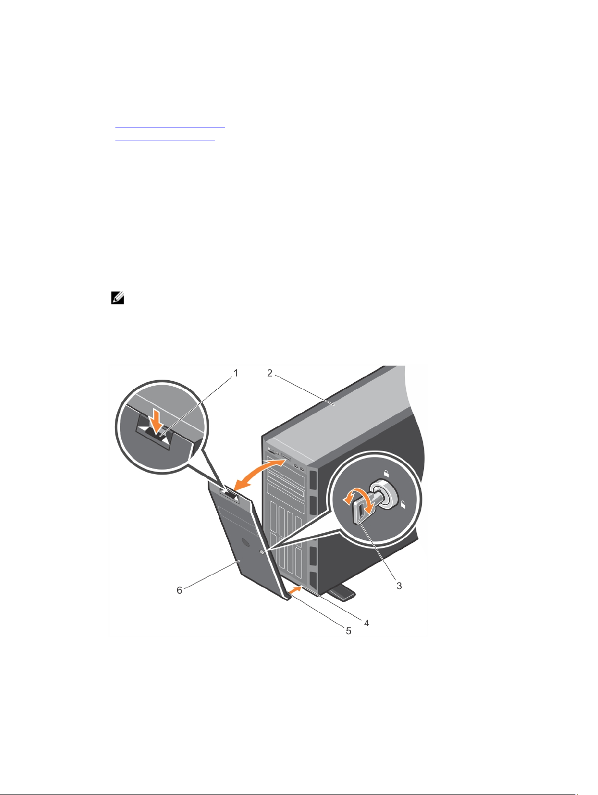
4. Reconnect the system to an electrical outlet and peripherals.
5. Power on the system, including any attached peripherals.
Related Links
Installing the system cover
Installing the front bezel
Recommended tools
You will need the #2 Phillips screwdriver to perform the removal and installation procedures.
Front bezel (optional)
Installing the front bezel
1. Locate and remove the bezel keys.
NOTE: There are two bezel keys attached to the bezel.
2. Insert the bezel tabs into the bezel tab slots in the chassis.
3. Insert the bezel tabs into the slots on the chassis.
4. Push the top end of the bezel toward the system until the bezel locks into place.
5. Lock the bezel.
Figure 10. Installing and removing the front bezel
1. release latch 2. system
50
Page 51

3. bezel key 4. slot on the chassis (2)
5. bezel tab (2) 6. bezel
Removing the front bezel
1. Unlock the bezel using the bezel keys.
2. Press the release latch at the top of the bezel.
3. Pull the top end of the bezel away from the system.
4. Remove the bezel by unhooking the bezel tabs from the slots at the bottom of the system.
System feet
The system feet provide stability to the system in the tower mode.
Removing the system feet
Prerequisites
NOTE: It is recommended that you remove the system feet only when you are converting the
system from the tower mode to the rack mode, or when you are replacing the system feet with the
wheel assembly.
1. Ensure that you read the Safety instructions.
2. Keep the #2 Phillips screwdriver ready.
3. Turn the system feet inward.
4. Lay the system on its side on a flat and stable surface.
Steps
Remove the screws securing the system feet to the base of the tower.
51
Page 52
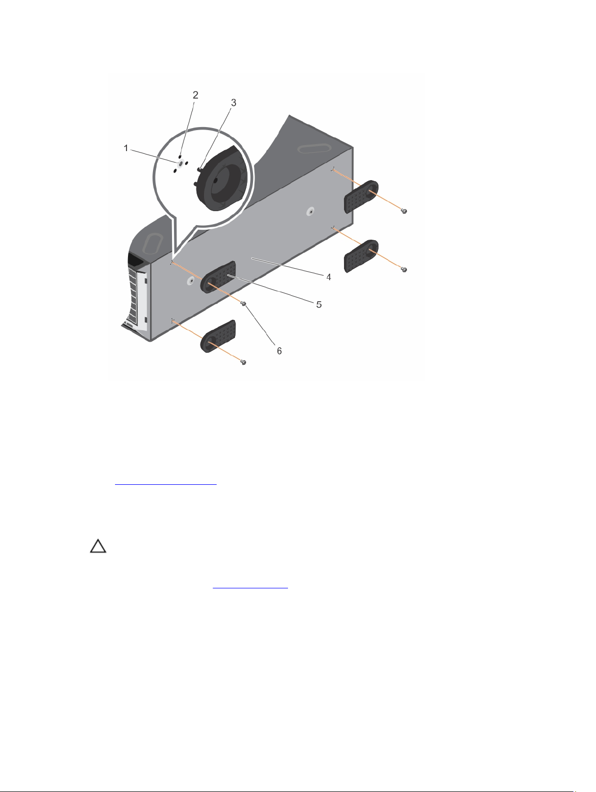
Figure 11. Removing and installing the system feet
1. screw hole (4) 2. slot (12)
3. tab (12) 4. base of the tower
5. system feet (4) 6. screw (4)
Related Links
Installing the system feet
Installing the system feet
Prerequisites
CAUTION: Installing the feet on a stand-alone tower system is necessary to provide a stable
foundation for the system. Failure to install the feet poses the risk of having the system tip over,
possibly causing bodily injury or damage to the system.
1. Ensure that you read the Safety instructions.
2. Keep the #2 Phillips screwdriver ready.
3. Lay the system on its side on a flat and stable surface.
Steps
1. Align the three tabs on the system feet with the three slots on the base of the chassis.
2. Secure the system feet to the base of the chassis by using the screws.
52
Page 53

Next steps
Place the system upright on a flat and stable surface, and turn the system feet outward.
Related Links
Removing the system feet
Caster wheels (optional)—tower mode
Caster wheels provide mobility to the system in the tower mode.
The caster wheel assembly consists of:
• Caster wheel units (front and back)
• Two screws for the caster wheel units
Installing caster wheels
Prerequisites
1. Ensure that you read the Safety instructions.
2. Keep the #2 Phillips screwdriver ready.
3. Lay the system on its side on a flat and stable surface with the base of the system extending off the
edge of the surface.
4. If installed, remove the system feet.
Steps
1. Align the two retention hooks on the back wheel unit with the two slots on the base of the chassis,
and insert the hooks into the slots.
2. Offset the back wheel to the back of the system and secure the unit in place using a single screw.
3. Align the two retention hooks on the front wheel with the two slots on the base of the chassis and
insert the hooks into the slots.
4. Offset the front wheel to the front and secure the unit in place using a screw.
53
Page 54
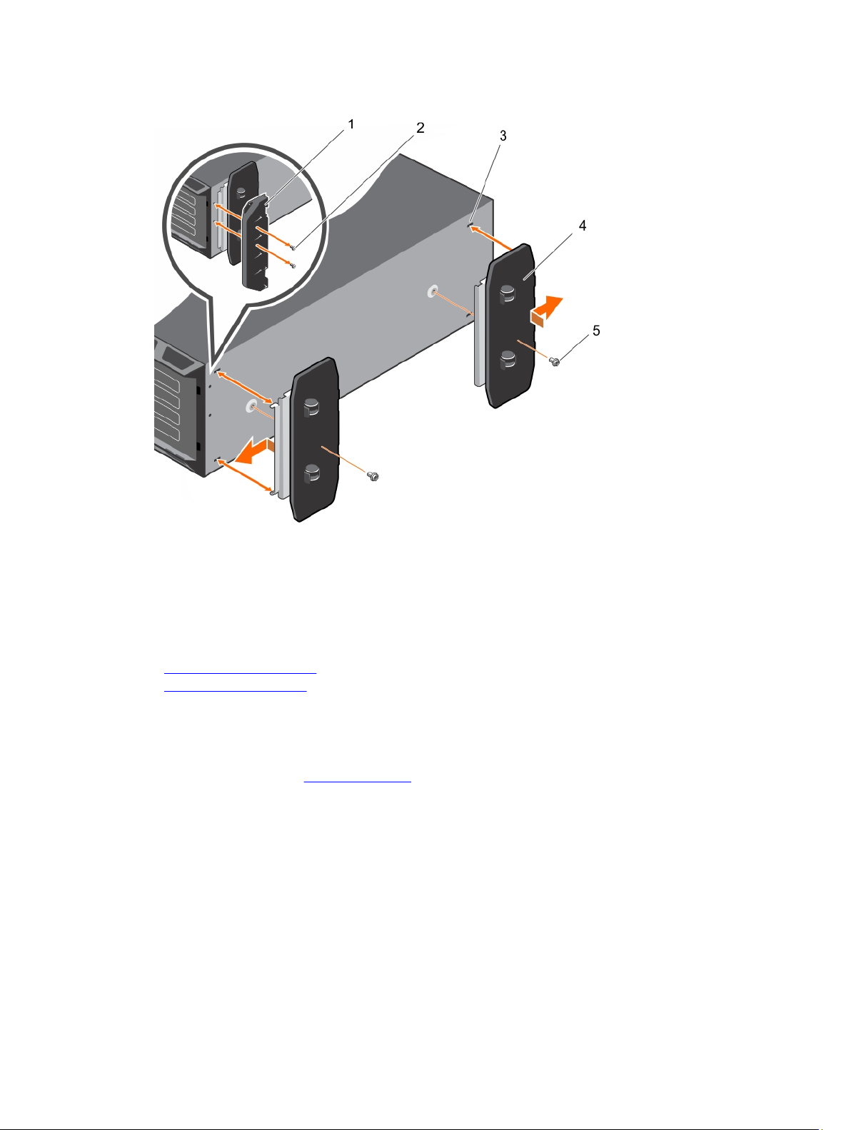
Figure 12. Removing and installing caster wheels
1. support unit 2. screw for support unit (2)
3. slot on base of the tower (4) 4. wheel assembly unit (2)
5. screw for wheel assembly (2)
Related Links
Removing the system feet
Removing caster wheels
Removing caster wheels
Prerequisites
1. Ensure that you read the Safety instructions.
2. Keep the #2 Phillips screwdriver ready.
3. Lay the system on a flat and stable surface with the wheels extending beyond the edge of the
surface.
Steps
1. Remove the screw securing the front wheel unit to the base of the chassis.
2. Offset the front wheel unit slightly to the back of the system to release the retention hooks, and pull
out the front wheel unit.
3. Remove the screw securing the back wheel unit to the base of the chassis.
4. Offset the back wheel unit slightly to the front of the system to release the retention hooks, and pull
out the back wheel unit.
54
Page 55
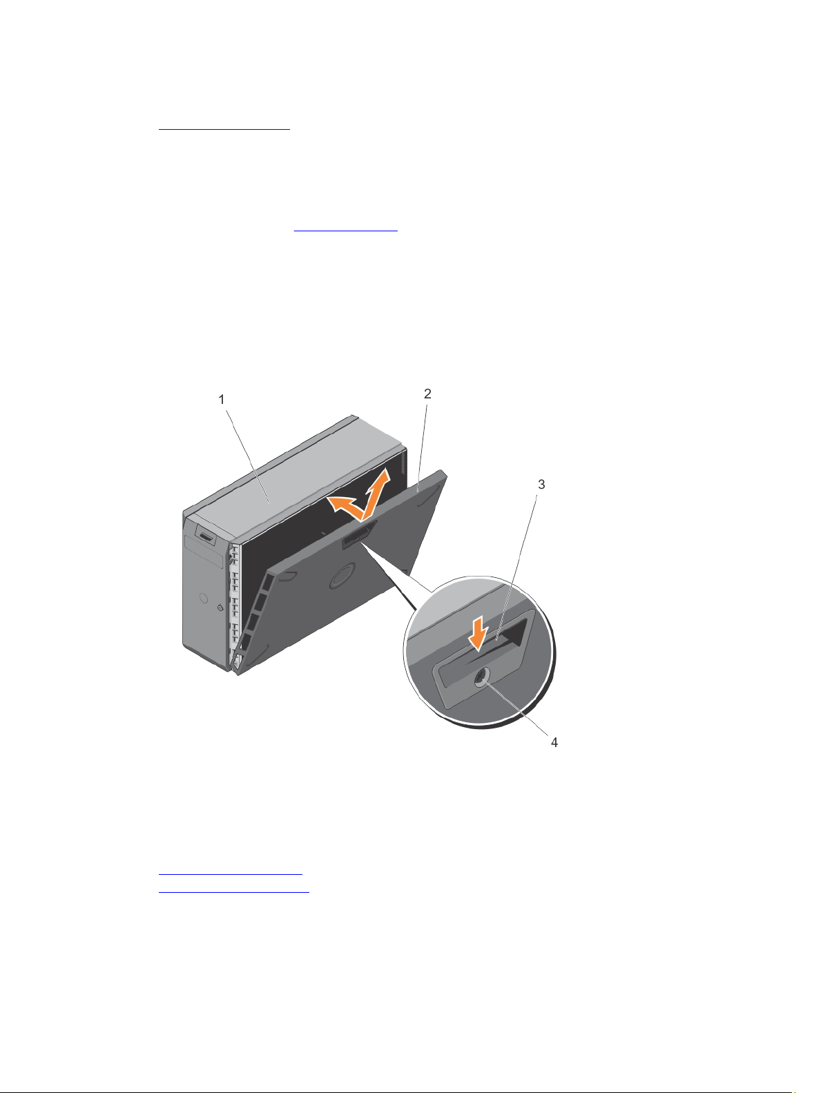
Related Links
Installing caster wheels
Removing the system cover
Prerequisites
1. Ensure that you read the Safety instructions.
2. Power off the system, including any attached peripherals.
3. Disconnect the system from the electrical outlet and disconnect the peripherals.
4. Remove the optional front bezel.
5. Lay the system on a flat and stable surface.
Steps
1. Turn the latch release lock to the unlock position.
2. Press the cover release latch and remove the system cover.
Figure 13. Removing and installing the system cover
1. system 2. system cover
3. cover release latch 4. cover release latch lock
Related Links
Removing the front bezel
Installing the system cover
55
Page 56

Installing the system cover
Prerequisites
Ensure that you read the Safety instructions.
Steps
1. Align the slots on the system cover with the tabs on the chassis.
2. Press the cover release latch, and push the cover toward the chassis until the latch locks into place.
3. Turn the latch release lock to the locked position.
Next steps
1. Place the system upright on its feet on a flat and stable surface.
2. If removed, install the front bezel.
3. Reconnect the system to its electrical outlet.
4. Power on the system, and reconnect any attached peripherals.
Related Links
Installing the front bezel
Removing the system cover
Inside the system
CAUTION: Many repairs may only be done by a certified service technician. You should only
perform troubleshooting and simple repairs as authorized in your product documentation, or as
directed by the online or telephone service and support team. Damage due to servicing that is
not authorized by Dell is not covered by your warranty. Read and follow the safety instructions
that came with the product.
NOTE: Components that are hot-swappable are marked orange and touch-points on the
components are marked blue.
56
Page 57
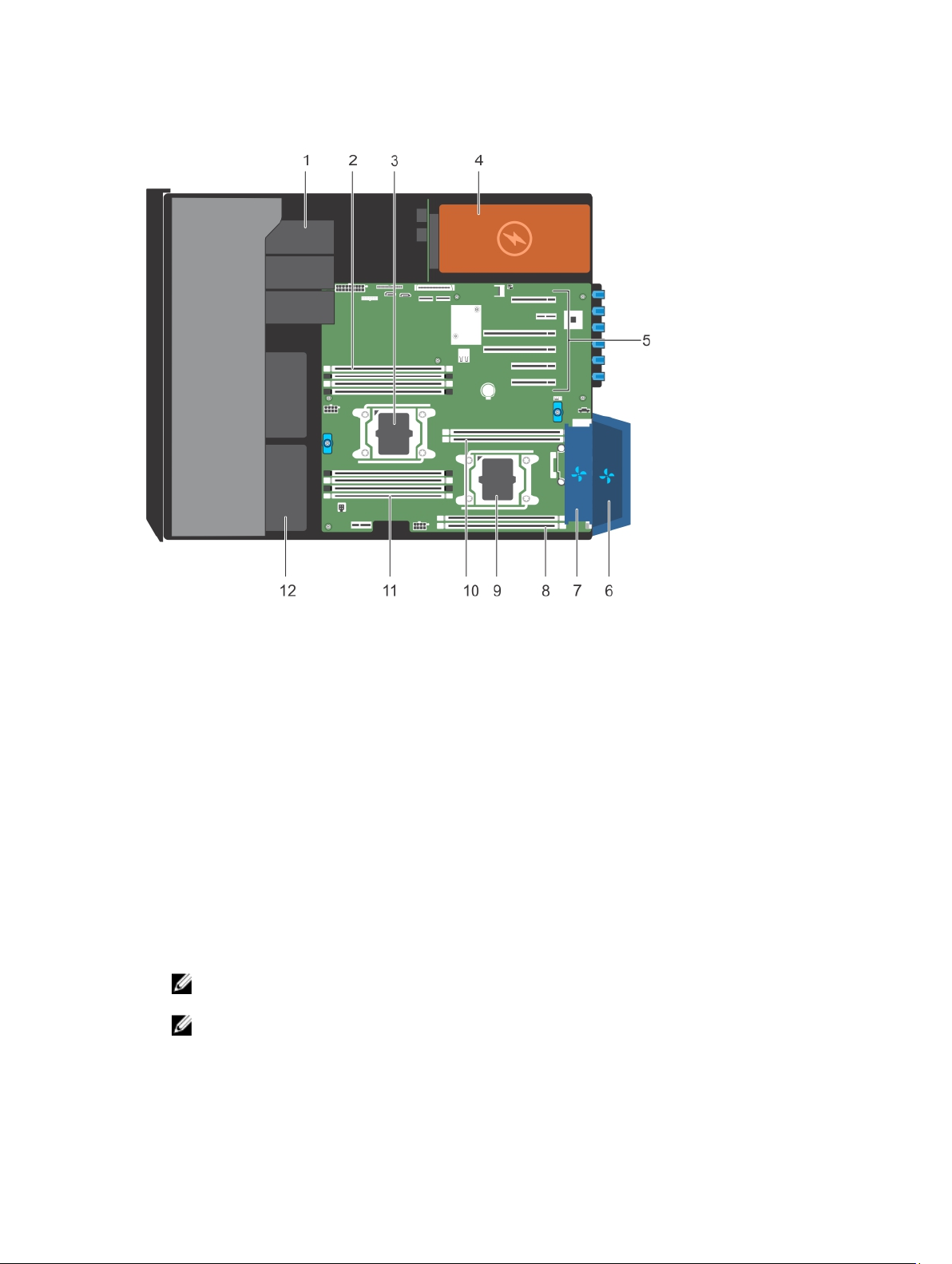
Figure 14. Inside the system
1. optical drive or tape drive 2. memory-module slots (4)
3. processor 1 4. power supply unit
5. expansion card slots 6. external cooling fan (optional)
7. internal cooling fan 8. memory-module slots (2)
9. processor 2 10. memory-module slots (2)
11. memory-module slots (4) 12. hard drives
Optical drives and tape drives (optional)
Your system supports one of the following configurations:
• Systems with cabled hard drives support one optical drive and one tape drive.
• Systems with hot-swappable hard drives support up to one optical drive and two tape drives.
NOTE: If your system is installed with a double-width GPU card, the system supports only one
5.25 inch removal media storage.
NOTE: You can also install a Dell PowerVault RD1000 removable media device on your system.
For systems with hot-swappable hard drives, the optical and tape drives can be configured as follows:
57
Page 58

Slot 1 SATA optical drive or PowerVault RD1000
Slot 2 PowerVault RD1000 or blank
Slot 3 SAS tape drive or blank
Removing the optical drive or tape drive
Prerequisites
CAUTION: Many repairs may only be done by a certified service technician. You should only
perform troubleshooting and simple repairs as authorized in your product documentation, or as
directed by the online or telephone service and support team. Damage due to servicing that is
not authorized by Dell is not covered by your warranty. Read and follow the safety instructions
that came with the product.
1. Ensure that you read the Safety instructions.
2. Follow the procedure listed in Before working inside your system.
Steps
1. Disconnect the power and data cables from the back of the optical/tape drive.
NOTE: Observe the routing of the power and data cable inside the chassis when you remove
them from the system board and the optical/tape drive. You must route these cables correctly
and in a similar manner when you replace them to prevent them from being pinched or
crimped.
2. To remove the optical/tape drive, push the release latch as indicated in the figure.
3. Slide the optical/tape drive out of the drive bay.
4. If you are not immediately replacing the optical/tape drive, install the optical/tape drive blank.
NOTE: Blanks must be installed on empty optical drive or tape drive slots to maintain FCC
certification of the system. The brackets also keep dust and dirt out of the system and aid in
proper cooling and airflow inside the system.
NOTE: The procedure to install an optical/tape drive blank is similar to the procedure to install
an optical/tape drive.
58
Page 59
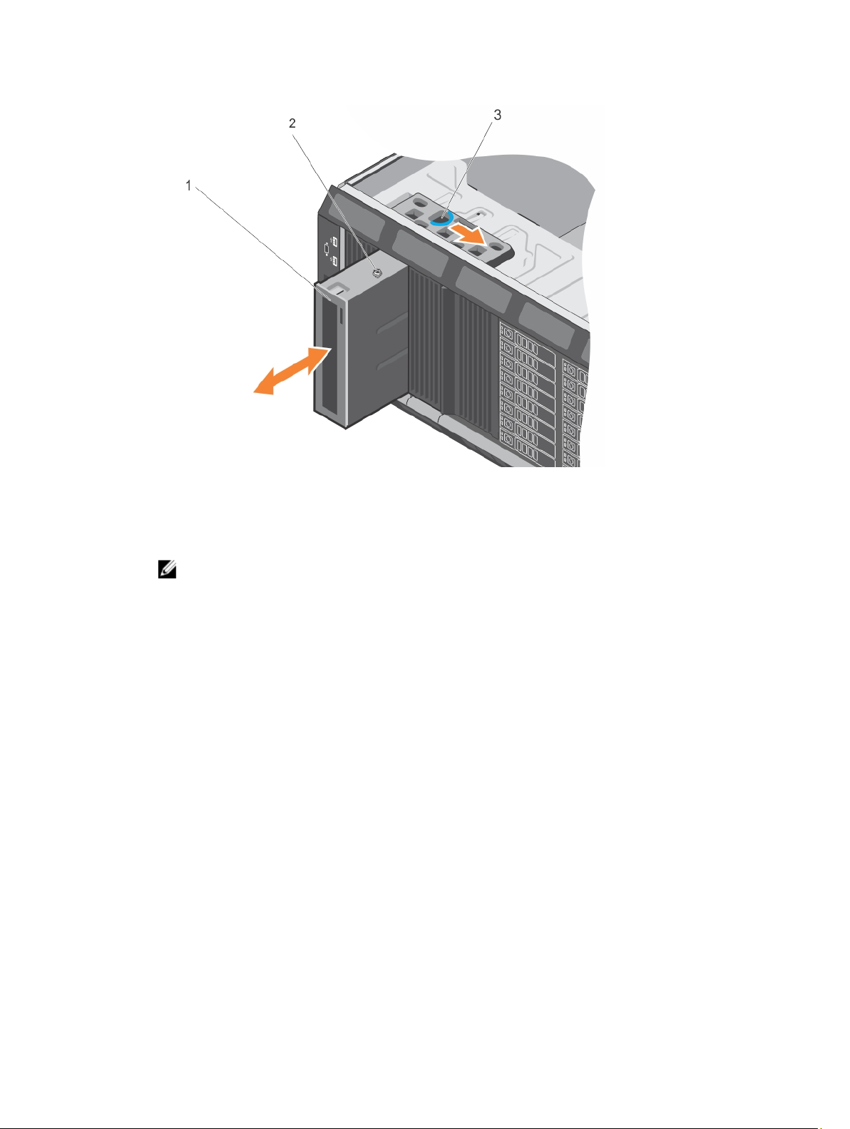
Figure 15. Removing and installing the optical drive or tape drive
1. optical drive/tape drive 2. guide
3. release latch
NOTE: The following figure shows the cabling diagram for an optical drive/tape drive with an
x16 backplane. All backplanes have an ODD connector.
59
Page 60
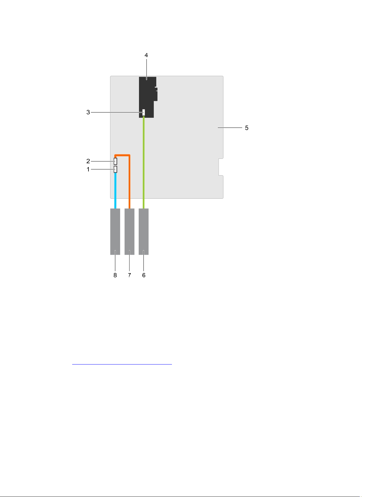
Figure 16. Cabling— optical drive and tape drive
1. optical drive connector on system board 2. tape drive connector on system board
3. SAS tape drive connector on the PERC
card
5. system board 6. SAS tape drive
7. tape drive 8. optical drive
Related Links
Installing the optical drive or tape drive
60
4. PERC card
Page 61

Installing the optical drive or tape drive
Prerequisites
CAUTION: Many repairs may only be done by a certified service technician. You should only
perform troubleshooting and simple repairs as authorized in your product documentation, or as
directed by the online or telephone service and support team. Damage due to servicing that is
not authorized by Dell is not covered by your warranty. Read and follow the safety instructions
that came with the product.
1. Ensure that you read the Safety instructions.
2. Follow the procedure listed in Before working inside your system.
Steps
1. Unpack and prepare the drive for installation.
For instructions, see the documentation that accompanied the drive.
If you are installing a SAS tape drive, you must have an internal tape adapter installed. For more
information on installing a SAS tape drive, see Installing an expansion card.
2. If installed, remove the old drive or the drive blank.
3. Align the guide on the drive with the slot on drive bay.
4. Slide the optical/tape drive into the slot until the optical/tape drive snaps into place.
5. Connect the power cable and data cables to the back of the optical/tape drive.
6. Connect the power cable to the backplane and the and data cable to the system board.
You can connect up to one optical drive with one SATA tape backup unit, and one SAS tape backup
unit using Dell OpenManage IT Assistant.
Next steps
Follow the procedure listed in After working inside your system.
Related Links
Removing the optical drive or tape drive
Cooling shroud
Removing the cooling shroud
Prerequisites
CAUTION: Many repairs may only be done by a certified service technician. You should only
perform troubleshooting and simple repairs as authorized in your product documentation, or as
directed by the online or telephone service and support team. Damage due to servicing that is
not authorized by Dell is not covered by your warranty. Read and follow the safety instructions
that came with the product.
CAUTION: Never operate your system with the cooling shroud removed. The system may get
overheated quickly, resulting in shutdown of the system and loss of data.
1. Ensure that you read the Safety instructions.
2. Follow the procedure listed in Before working inside your system.
61
Page 62
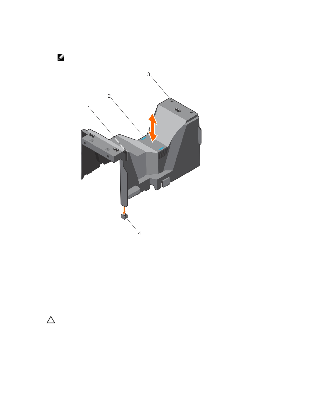
Steps
Holding the touch points, lift the cooling shroud from the system.
NOTE: Systems with x16 hard-drive backplanes use a different cooling shroud. To ensure
proper cooling, always install the cooling shroud provided with your system.
Figure 17. Removing and installing the cooling shroud — 3.5 inch hard-drive system
1. chassis intrusion switch 2. touch points (2)
3. slots (2) 4. chassis intrusion-switch connector on
Related Links
Installing the cooling shroud
the system board
Installing the cooling shroud
Prerequisites
CAUTION: Many repairs may only be done by a certified service technician. You should only
perform troubleshooting and simple repairs as authorized in your product documentation, or as
directed by the online or telephone service and support team. Damage due to servicing that is
not authorized by Dell is not covered by your warranty. Read and follow the safety instructions
that came with the product.
62
Page 63

Ensure that you read the Safety instructions.
CAUTION: Do not operate the system with the cover removed for a duration exceeding 5
minutes.
NOTE: For proper seating of the cooling shroud in the system chassis, ensure that the cables inside
the system are routed along the chassis wall and secured using the cable securing clips.
Steps
1. Align the two slots on the cooling shroud with the tabs on the internal cooling fan.
2. Lower the cooling shroud into the chassis until the two slots on the cooling shroud are flush with the
tabs on the internal cooling fan.
NOTE: When the cooling shroud is properly seated, the chassis intrusion-switch on the cooling
shroud connects to the chassis intrusion-switch connector on the system board.
Related Links
Removing the cooling shroud
Hot-swappable hard drives
Your system supports Entry Hard Drives and Enterprise Class Hard Drives. Entry Hard Drives are designed
for 5x8 operating environment with less workload rating to drives and Enterprise Class Drives are
designed for 24x7 operating environment. Selecting the correct drive class will enable the critical areas of
quality, functionality, performance, and reliability to be optimized for the target implementation.
NOTE: Do not mix Enterprise Class Drives with Entry Hard Drives.
For more information on these hard drives, see the 512e and 4Kn Disk Formats whitepaper and 4K Sector
HDD FAQ document at dell.com/poweredgemanuals.
Choosing the right drive type depends on the usage pattern. Improper use of Entry Hard Drives (workload
rating exceed 55TB/year) will lead to significant risk and increase the drives failure rate.
All hard drives connect to the system board through the hard-drive backplane. Hard drives are supplied in
hot-swappable hard-drive carriers that fit in the hard-drive slots.
CAUTION: Before attempting to remove or install a hard drive while the system is running, see the
documentation for the storage controller card to ensure that the host adapter is configured
correctly to support hot-swap hard drive removal and insertion.
CAUTION: Do not turn off or restart your system while the hard drive is being formatted. Doing so
can cause a hard drive failure.
Use only hard drives that have been tested and approved for use with the hard-drive backplane.
When you format a hard drive, allow enough time for the formatting to be completed. Be aware that
high-capacity hard drives can take a number of hours to format.
63
Page 64
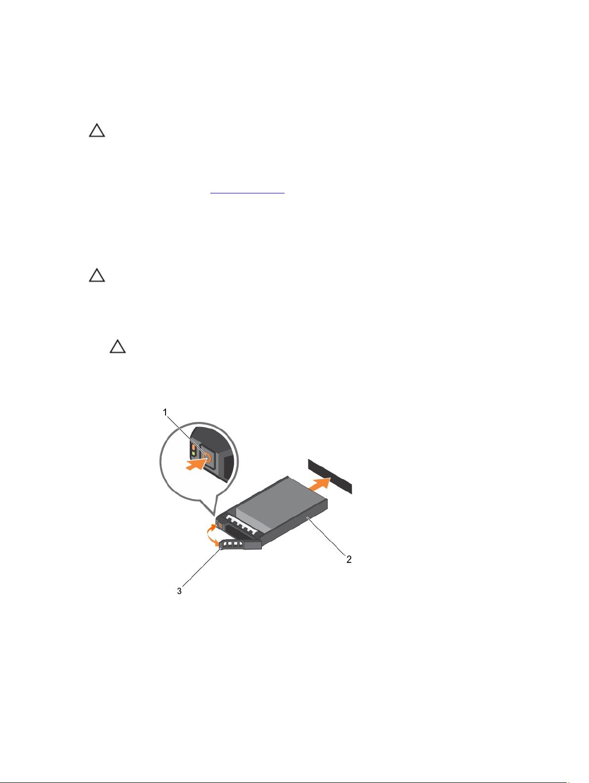
Removing a hot-swap hard drive
Prerequisites
CAUTION: Many repairs may only be done by a certified service technician. You should only
perform troubleshooting and simple repairs as authorized in your product documentation, or as
directed by the online or telephone service and support team. Damage due to servicing that is
not authorized by Dell is not covered by your warranty. Read and follow the safety instructions
that came with the product.
1. Ensure that you read the Safety instructions.
2. If installed, remove the front bezel.
3. Using the management software, prepare the hard drive for removal. For more information, see the
documentation for the storage controller.
If the hard drive is online, the green activity/fault indicator flashes as the drive is turned off. You can
remove the hard-drive when the hard-drive indicators turn off.
CAUTION: To prevent data loss, ensure that your operating system supports hot-swap drive
installation. See the documentation supplied with your operating system.
Steps
1. Press the release button to open the hard-drive carrier release handle.
2. Slide the hard-drive carrier out of the hard-drive slot.
CAUTION: To maintain proper system cooling, all empty hard-drive slots must have harddrive blanks installed.
3. If you are not replacing the hard drive immediately, insert a hard-drive blank in the empty hard-drive
slot.
Figure 18. Removing and installing a hot-swap hard drive
1. release button 2. hard-drive carrier
3. hard-drive carrier handle
64
Page 65
Next steps
If removed, install the front bezel.
Installing a hot-swap hard drive
Prerequisites
CAUTION: Many repairs may only be done by a certified service technician. You should only
perform troubleshooting and simple repairs as authorized in your product documentation, or as
directed by the online or telephone service and support team. Damage due to servicing that is
not authorized by Dell is not covered by your warranty. Read and follow the safety instructions
that came with the product.
CAUTION: Use only hard drives that have been tested and approved for use with the hard-drive
backplane.
CAUTION: Combining SAS and SATA hard drives in the same RAID volume is not supported.
CAUTION: When installing a hard drive, ensure that the adjacent drives are fully installed.
Inserting a hard-drive carrier and attempting to lock its handle next to a partially installed carrier
can damage the partially installed carrier's shield spring and make it unusable.
CAUTION: To prevent data loss, ensure that your operating system supports hot-swap drive
installation. See the documentation supplied with your operating system.
CAUTION: When a replacement hot-swappable hard drive is installed and the system is powered
on, the hard drive automatically begins to rebuild. Make absolutely sure that the replacement
hard drive is blank or contains data that you wish to have over-written. Any data on the
replacement hard drive is immediately lost after the hard drive is installed.
Steps
1. If a hard-drive blank is installed in the hard-drive slot, remove it.
2. Install a hard drive in the hard-drive carrier.
3. Press the release button on the front of the hard-drive carrier and open the hard-drive carrier handle.
4. Insert the hard-drive carrier into the hard-drive slot until the carrier comes in contact with the
backplane.
5. Close the hard-drive carrier handle to lock the hard drive in place.
Next steps
If applicable, install the front bezel.
Removing a hard-drive blank
Prerequisites
CAUTION: Many repairs may only be done by a certified service technician. You should only
perform troubleshooting and simple repairs as authorized in your product documentation, or as
directed by the online or telephone service and support team. Damage due to servicing that is
not authorized by Dell is not covered by your warranty. Read and follow the safety instructions
that came with the product.
CAUTION: To maintain proper system cooling, all empty hard-drive slots must have hard-drive
blanks installed.
1. Ensure that you read the Safety instructions.
2. If installed, remove the bezel.
65
Page 66

Steps
Press the release button and slide the hard-drive blank out of the hard-drive slot.
Figure 19. Removing and installing a 2.5 inch hard-drive blank
1. hard-drive blank 2. release button
Figure 20. Removing and installing a 3.5 inch hard-drive blank
1. hard-drive blank 2. release button
Installing a hard-drive blank
Prerequisites
1. Ensure that you read the Safety instructions.
2. If installed, remove the front bezel.
66
Page 67
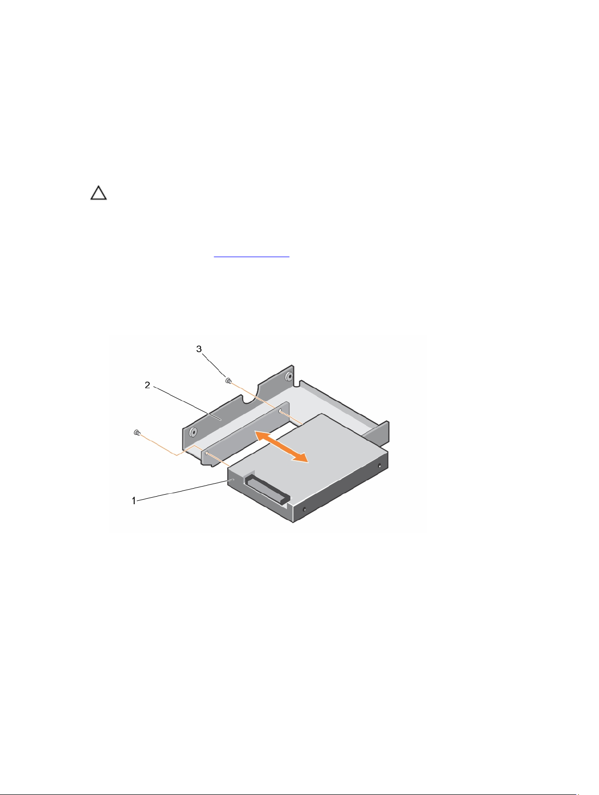
Steps
Insert the hard-drive blank into the hard-drive slot until the release button clicks into place.
Next steps
If applicable, install the front bezel.
Installing a 2.5 inch hard drive into a 3.5 inch hard-drive adapter
Prerequisites
CAUTION: Many repairs may only be done by a certified service technician. You should only
perform troubleshooting and simple repairs as authorized in your product documentation, or as
directed by the online or telephone service and support team. Damage due to servicing that is
not authorized by Dell is not covered by your warranty. Read and follow the safety instructions
that came with the product.
1. Ensure that you read the Safety instructions.
2. Keep the #2 Phillips screwdriver ready.
Steps
1. Align the screw holes on the 2.5 inch hard drive with the screw holes on the 3.5 inch hard-drive
adapter.
2. Install the screws to secure the hard drive to the hard-drive adapter.
Figure 21. Removing and installing a 2.5 inch hard drive into a 3.5 inch hard-drive adapter
1. 2.5 inch hard drive 2. 3.5 inch hard-drive adapter
3. screw (2)
67
Page 68

Removing a 2.5 inch hard drive from a 3.5 inch hard-drive adapter
Prerequisites
CAUTION: Many repairs may only be done by a certified service technician. You should only
perform troubleshooting and simple repairs as authorized in your product documentation, or as
directed by the online or telephone service and support team. Damage due to servicing that is
not authorized by Dell is not covered by your warranty. Read and follow the safety instructions
that came with the product.
1. Ensure that you read the Safety instructions.
2. Keep the #2 Phillips screwdriver ready.
NOTE: A 2.5 inch hard drive is installed in a 3.5 inch hard-drive adapter, which is then installed in the
3.5 inch hard-drive carrier.
Steps
1. Remove the screws from the side of the 3.5 inch hard-drive adapter.
2. Remove the hard drive from the hard-drive adapter.
Installing a hard-drive adapter into a hard-drive carrier
Prerequisites
CAUTION: Many repairs may only be done by a certified service technician. You should only
perform troubleshooting and simple repairs as authorized in your product documentation, or as
directed by the online or telephone service and support team. Damage due to servicing that is
not authorized by Dell is not covered by your warranty. Read and follow the safety instructions
that came with the product.
1. Ensure that you read the Safety instructions.
2. Keep the #2 Phillips screwdriver ready.
Steps
1. Insert the hard-drive adapter into the hard-drive carrier with the connector end of the hard drive
toward the back of the hard-drive carrier.
2. Align the screw holes on the hard drive with the holes on the hard-drive carrier.
3. Install the screws to secure the hard drive to the hard-drive carrier.
68
Page 69
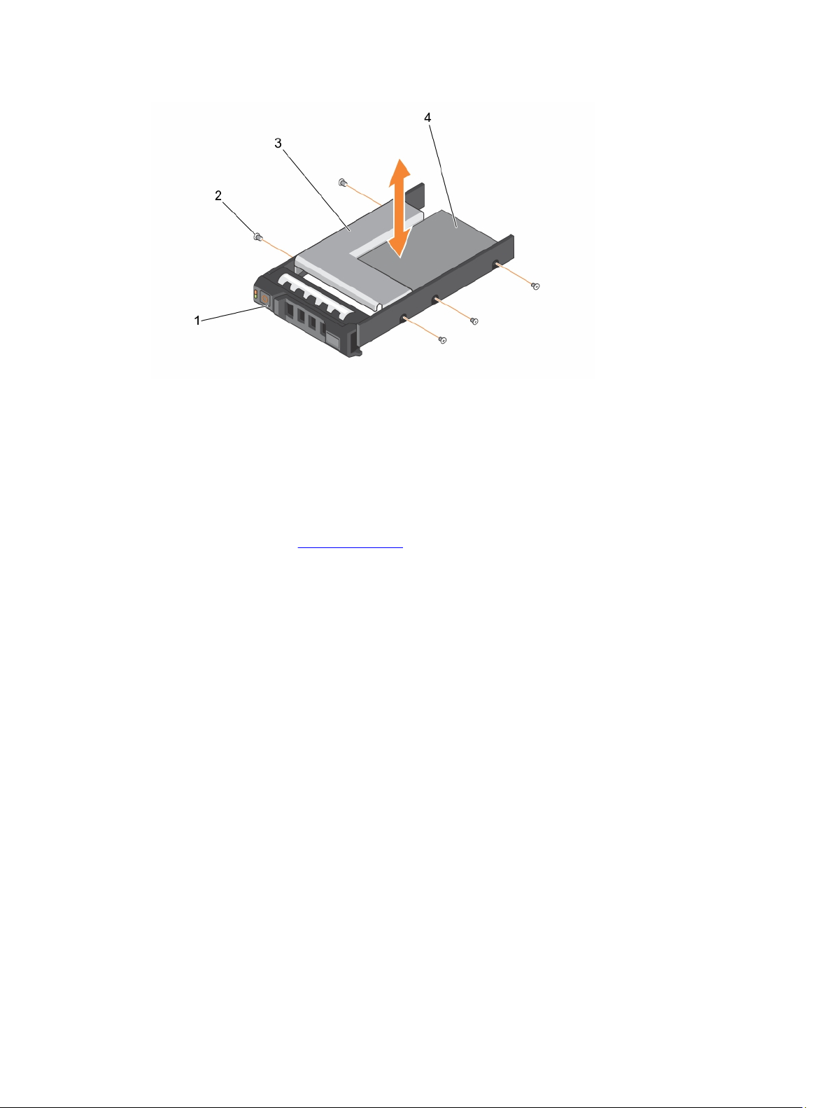
Figure 22. Removing and installing a hard-drive adapter into a 3.5 inch hard-drive carrier
1. 3.5 inch hard-drive carrier 2. screw (5)
3. hard-drive adapter 4. 2.5 inch hard drive
Removing a hard-drive adapter from a hard-drive carrier
Prerequisites
1. Ensure that you read the Safety instructions.
2. Keep the #2 Phillips screwdriver ready.
Steps
1. Remove the screws from the slide rails on the hard-drive carrier.
2. Lift the hard-drive adapter out of the hard-drive carrier.
Removing a hard drive from a hard-drive carrier
Prerequisites
1. Keep the #2 Phillips screwdriver ready.
2. Remove the hard-drive carrier from the system.
Steps
1. Remove the screws from the slide rails on the hard-drive carrier.
2. Lift the hard drive out of the hard-drive carrier.
69
Page 70
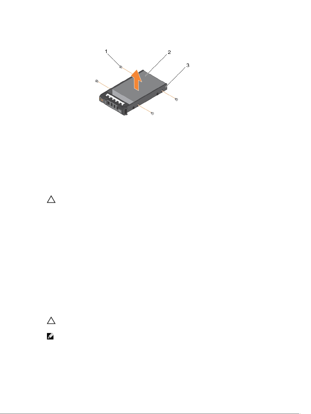
Figure 23. Removing and installing a hard drive into a hard-drive carrier
1. screw (4) 2. hard drive
3. hard-drive carrier
Installing a hard drive into a hard-drive carrier
Prerequisites
CAUTION: Many repairs may only be done by a certified service technician. You should only
perform troubleshooting and simple repairs as authorized in your product documentation, or as
directed by the online or telephone service and support team. Damage due to servicing that is
not authorized by Dell is not covered by your warranty. Read and follow the safety instructions
that came with the product.
Keep the #2 Phillips screwdriver ready.
Steps
1. Insert the hard drive into the hard-drive carrier with the connector end of the hard drive toward the
back of the hard-drive carrier.
2. Align the screw holes on the hard drive with the screw holes on the hard-drive carrier.
When aligned correctly, the back of the hard drive is flush with the back of the hard-drive carrier.
3. Attach the screws to secure the hard drive to the hard-drive carrier.
Cabled hard drives
Your system supports up to four 3.5 inch (SAS or SATA) cabled hard drives. Cabled hard drives are
installed in an internal hard-drive bay.
CAUTION: Do not turn off or restart your system while the hard drive is being formatted. Doing so
can cause a hard drive failure.
NOTE: Use only hard drives that have been tested and approved for use with your system.
70
Page 71
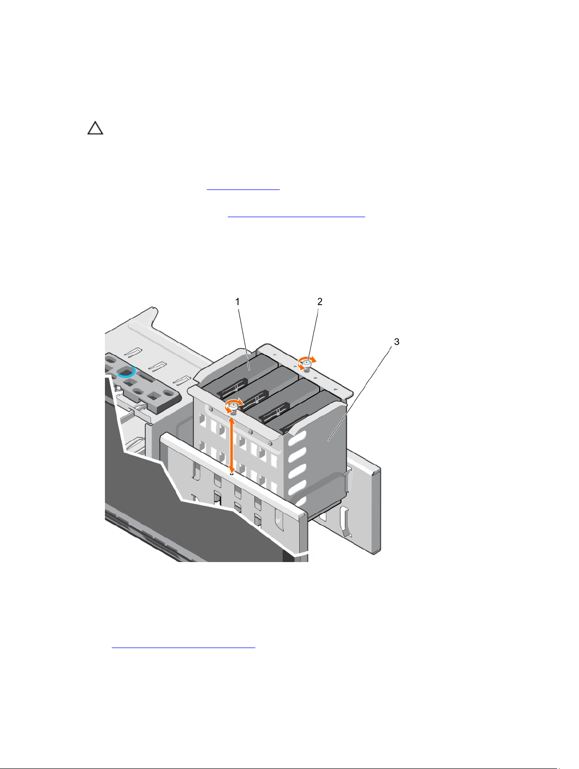
Removing the internal hard-drive bay
Prerequisites
CAUTION: Many repairs may only be done by a certified service technician. You should only
perform troubleshooting and simple repairs as authorized in your product documentation, or as
directed by the online or telephone service and support team. Damage due to servicing that is
not authorized by Dell is not covered by your warranty. Read and follow the safety instructions
that came with the product.
1. Ensure that you read the Safety instructions.
2. Keep the #2 Phillips screwdriver ready.
3. Follow the procedure listed in Before working inside your system.
Steps
1. Disconnect the data and power cable(s) from the hard drive(s).
2. Loosen the two captive screws securing the internal hard-drive bay to the chassis.
3. Lift the internal hard-drive bay up and out of the chassis.
Figure 24. Installing and removing the internal hard-drive bay
1. cabled hard drives (4) 2. captive screws (2)
3. internal hard-drive bay
Related Links
Installing the internal hard-drive bay
71
Page 72

Installing the internal hard-drive bay
Prerequisites
CAUTION: Many repairs may only be done by a certified service technician. You should only
perform troubleshooting and simple repairs as authorized in your product documentation, or as
directed by the online or telephone service and support team. Damage due to servicing that is
not authorized by Dell is not covered by your warranty. Read and follow the safety instructions
that came with the product.
1. Ensure that you read the Safety instructions.
2. Keep the #2 Phillips screwdriver ready.
Steps
1. Align the internal hard-drive bay with the tabs on the chassis and slide the internal hard-drive bay
into the chassis.
2. Secure the internal hard-drive bay to the chassis using the two captive screws.
3. Connect the data and power cables to the hard drive(s).
Next steps
Follow the procedure listed in After working inside your system.
Related Links
Removing the internal hard-drive bay
Removing a cabled hard drive
Prerequisites
CAUTION: Many repairs may only be done by a certified service technician. You should only
perform troubleshooting and simple repairs as authorized in your product documentation, or as
directed by the online or telephone service and support team. Damage due to servicing that is
not authorized by Dell is not covered by your warranty. Read and follow the safety instructions
that came with the product.
1. Ensure that you read the Safety instructions.
2. Keep the #2 Phillips screwdriver ready.
3. Follow the procedure listed in Before working inside your system.
Steps
1. Remove the power and data cables from the hard drive(s) in the internal hard-drive bay.
2. Remove the internal hard-drive bay.
3. Remove the four screws securing the hard drive to the internal hard-drive bay.
4. Remove the hard drive from the internal hard-drive bay.
72
Page 73
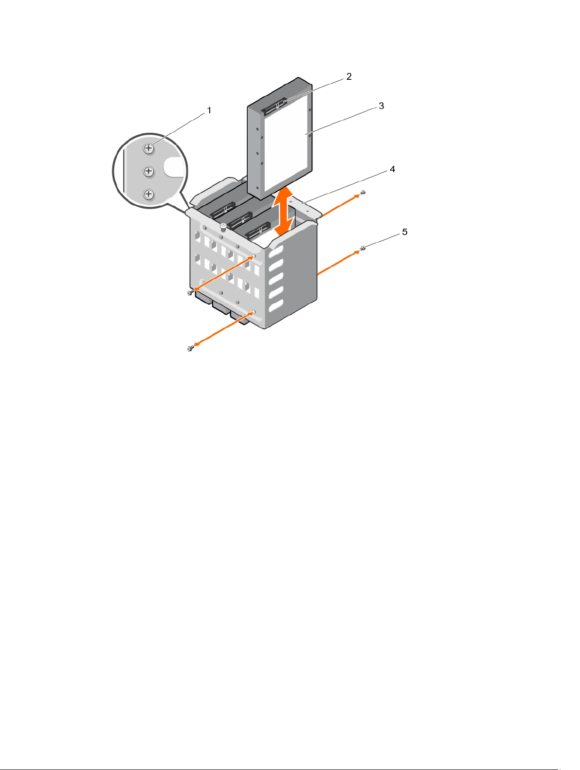
Figure 25. Removing and installing a cabled hard drive
1. spare screws 2. hard drive connector
3. hard drive 4. internal hard-drive bay
5. screws (4)
73
Page 74
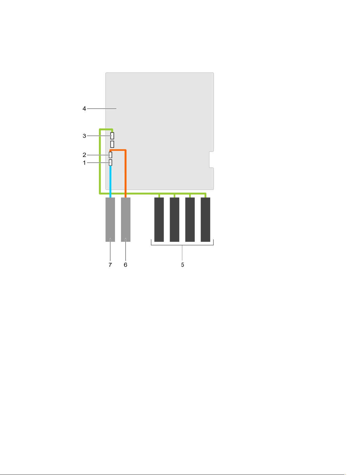
Figure 26. Cabling—Cabled hard-drives
74
1. SATA optical drive connector on system
board
2. SATA tape drive connector on system
board
3. SATA A connector on system board 4. system board
5. hard drives 6. tape drive
7. optical drive
Page 75
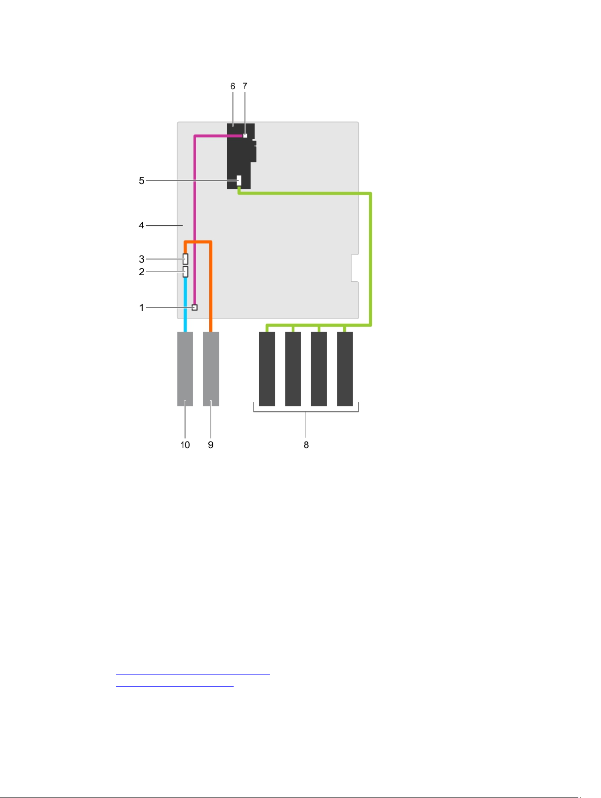
Figure 27. Cabling—Cabled hard-drives with a PERC card
1. front-panel HDD LED controller
connector on the system board
3. SATA tape drive connector on system
2. SATA optical drive connector on system
board
4. system board
board
5. SAS connector on PERC card 6. PERC card
7. front-panel HDD LED controller
8. hard drives
connector on the PERC card
9. tape drive 10. optical drive
Next steps
1. Install the internal hard-drive bay into the chassis.
2. If disconnected, reconnect the power and data cable(s) to the remaining hard drive(s) in the internal
hard-drive bay.
Related Links
Removing the internal hard-drive bay
Installing a cabled hard drive
75
Page 76

Installing a cabled hard drive
Prerequisites
CAUTION: Many repairs may only be done by a certified service technician. You should only
perform troubleshooting and simple repairs as authorized in your product documentation, or as
directed by the online or telephone service and support team. Damage due to servicing that is
not authorized by Dell is not covered by your warranty. Read and follow the safety instructions
that came with the product.
1. Ensure that you read the Safety instructions.
2. Keep the #2 Phillips screwdriver ready.
3. Follow the procedure listed in Before working inside your system.
4. Disconnect the power and data cables from the hard drive(s) in the internal hard-drive bay.
5. Remove the internal hard-drive bay.
Steps
1. Insert the hard drive into the internal hard-drive bay with the hard-drive connector facing outward.
2. Secure the hard drive to the internal hard-drive bay using the four screws.
NOTE: When installing new hard drives into the internal hard-drive bay, use the spare harddrive screws attached to the hard-drive bay.
Next steps
1. Follow the procedure listed in After working inside your system.
2. Install the internal hard-drive bay into the chassis.
3. Connect the power and data cables to the hard drive(s).
4. Enter System Setup and ensure that the hard drive controller is enabled.
5. Exit System Setup and restart the system.
6. Install any software required for operating the hard drive as described in the documentation for the
hard drive.
Related Links
Removing the internal hard-drive bay
Installing the internal hard-drive bay
Removing a cabled hard drive
Hard-drive backplane
Your system supports one of the following configurations:
• x8 SAS/SATA backplane for 3.5 inch hard drives
NOTE: The x8 backplane also supports up to eight 2.5 inch (SAS, SATA, or SSD) hot-swappable
hard drives installed in 3.5 inch hard-drive adapters, which are then installed in the 3.5 inch harddrive carriers.
• x16 SAS/SATA backplane for 2.5 inch hard drives
NOTE: Only systems with hot-swappable hard drives support hard-drive backplanes.
76
Page 77
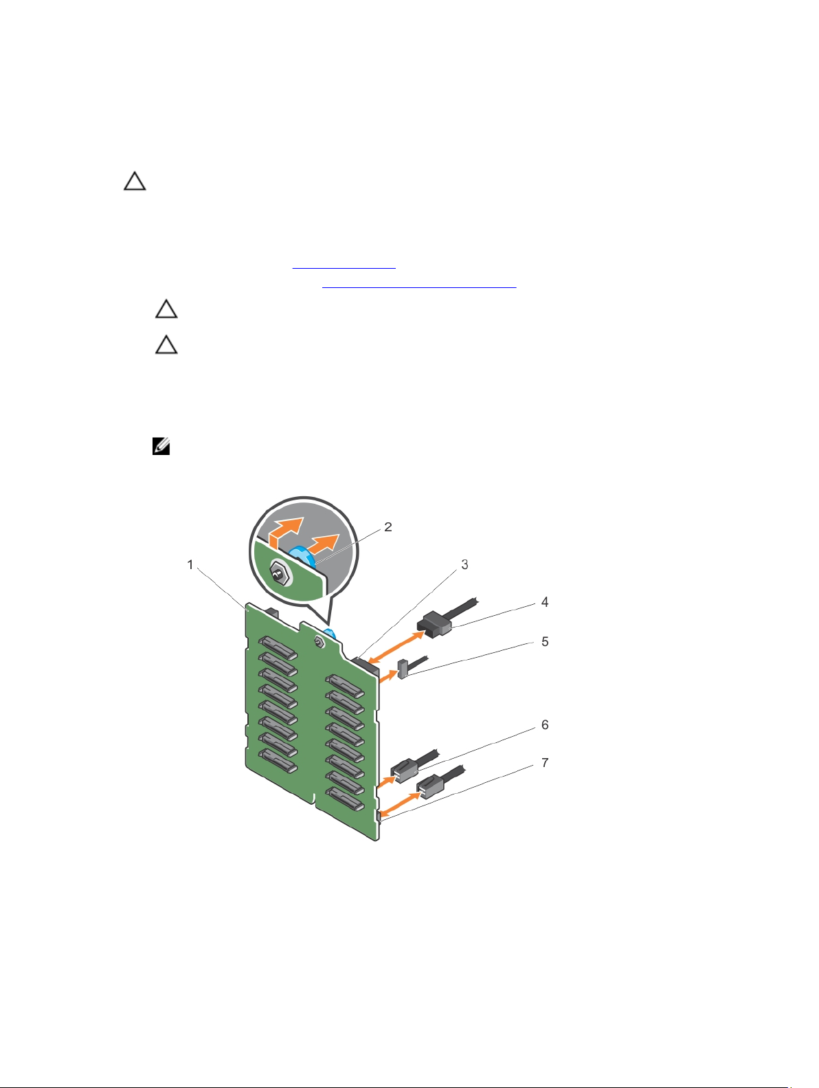
Removing the hard-drive backplane
Prerequisites
CAUTION: Many repairs may only be done by a certified service technician. You should only
perform troubleshooting and simple repairs as authorized in your product documentation, or as
directed by the online or telephone service and support team. Damage due to servicing that is
not authorized by Dell is not covered by your warranty. Read and follow the safety instructions
that came with the product.
1. Ensure that you read the Safety instructions.
2. Follow the procedure listed in Before working inside your system.
CAUTION: To prevent damage to the drives and backplane, remove the hard drives from the
system before removing the backplane.
CAUTION: Note the slot number of each hard drive and temporarily label the slots before
removing the hard drives so that you can replace them in the same locations.
3. Remove all hard drives.
Steps
1. Disconnect the SAS, power, and signal cables from the hard-drive backplane.
NOTE: For the x8 backplane, press the SAS connector and push the connector toward the top
of the system to release the SAS cable from the backplane.
2. Pull the release pin and lift the backplane out of the system.
Figure 28. Removing and installing an x16 hard-drive backplane
1. x16 hard-drive backplane 2. release pin
3. power connector 4. power cable
77
Page 78
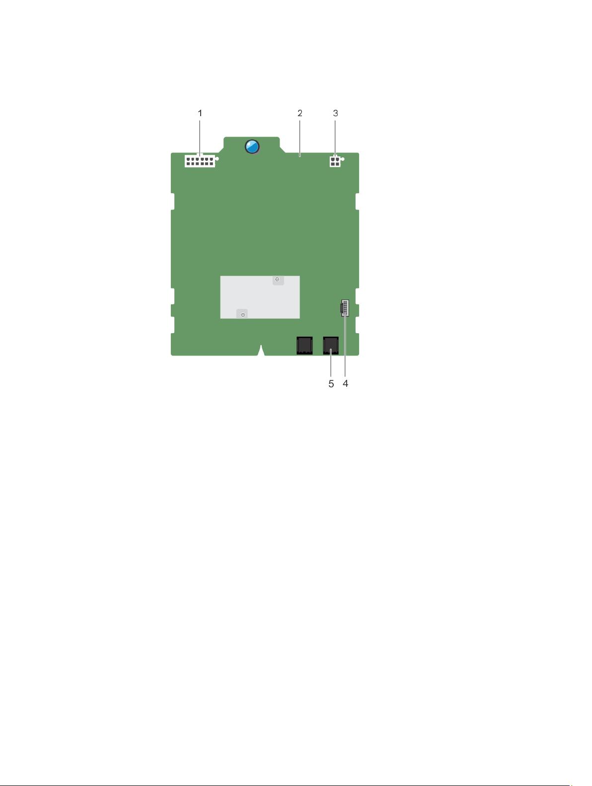
5. signal cable 6. SAS cable
7. SAS connector
Figure 29. Connectors on an x16 hard-drive backplane
1. backplane power connector 2. x16 backplane
3. power connector for the optical and tape
4. signal connector
drives
5. SAS A connector
78
Page 79
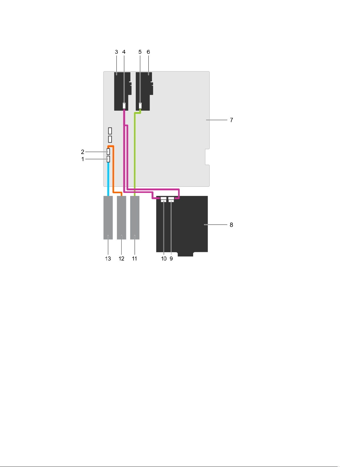
Figure 30. Cabling—x16 hard-drive backplane with two PERC cards
1. SATA optical drive connector on system
board
2. SATA tape drive connector on system
board
3. PERC card 4. SAS connector on PERC card
5. SAS connector on PERC card 6. PERC card
7. system board 8. x16 backplane
9. SAS B connector on the x16 backplane 10. SAS A connector on the x16 backplane
11. SAS tape drive 12. SATA tape drive
13. optical drive
79
Page 80
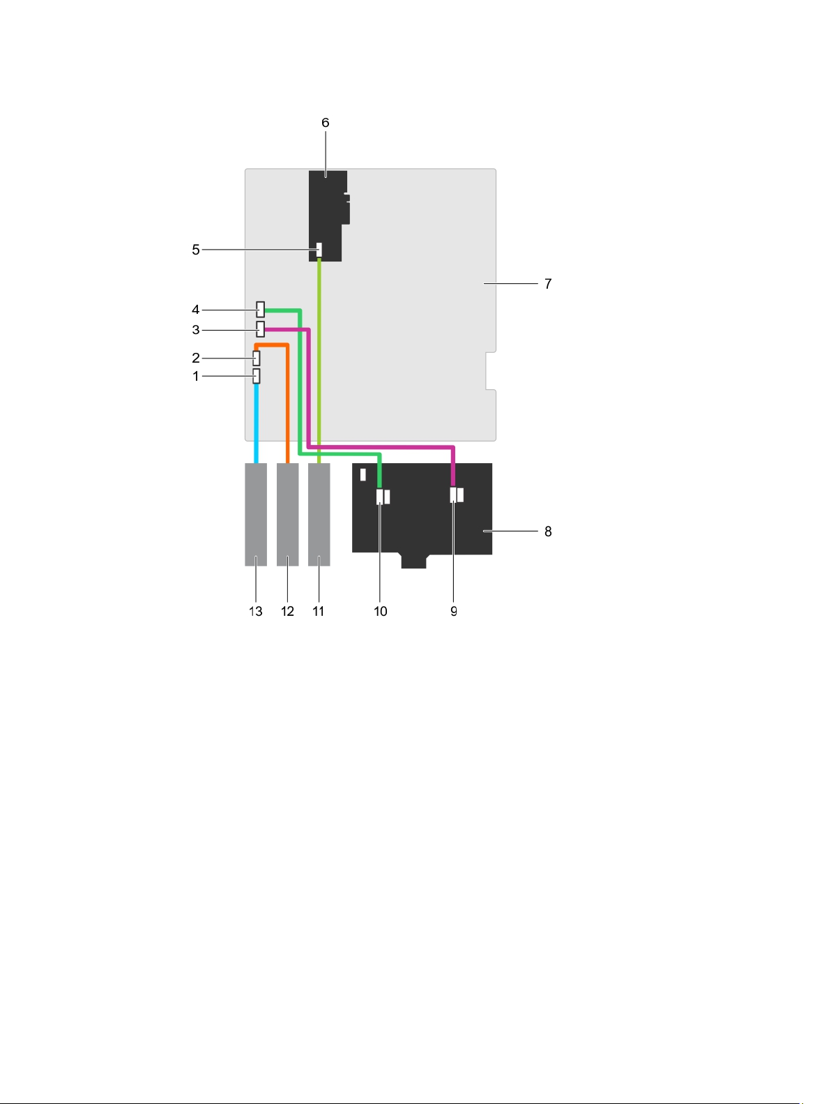
Figure 31. Cabling—x8 hard-drive backplane with one PERC card
80
1. SATA optical drive connector on system
board
2. SATA tape drive connector on system
board
3. SATA B connector on system board 4. SATA A connector on system board
5. SAS connector on PERC card 6. PERC card
7. system board 8. x8 backplane
9. SAS B connector on backplane 10. SAS A connector on backplane
11. SAS tape drive 12. SATA tape drive
13. optical drive
Page 81
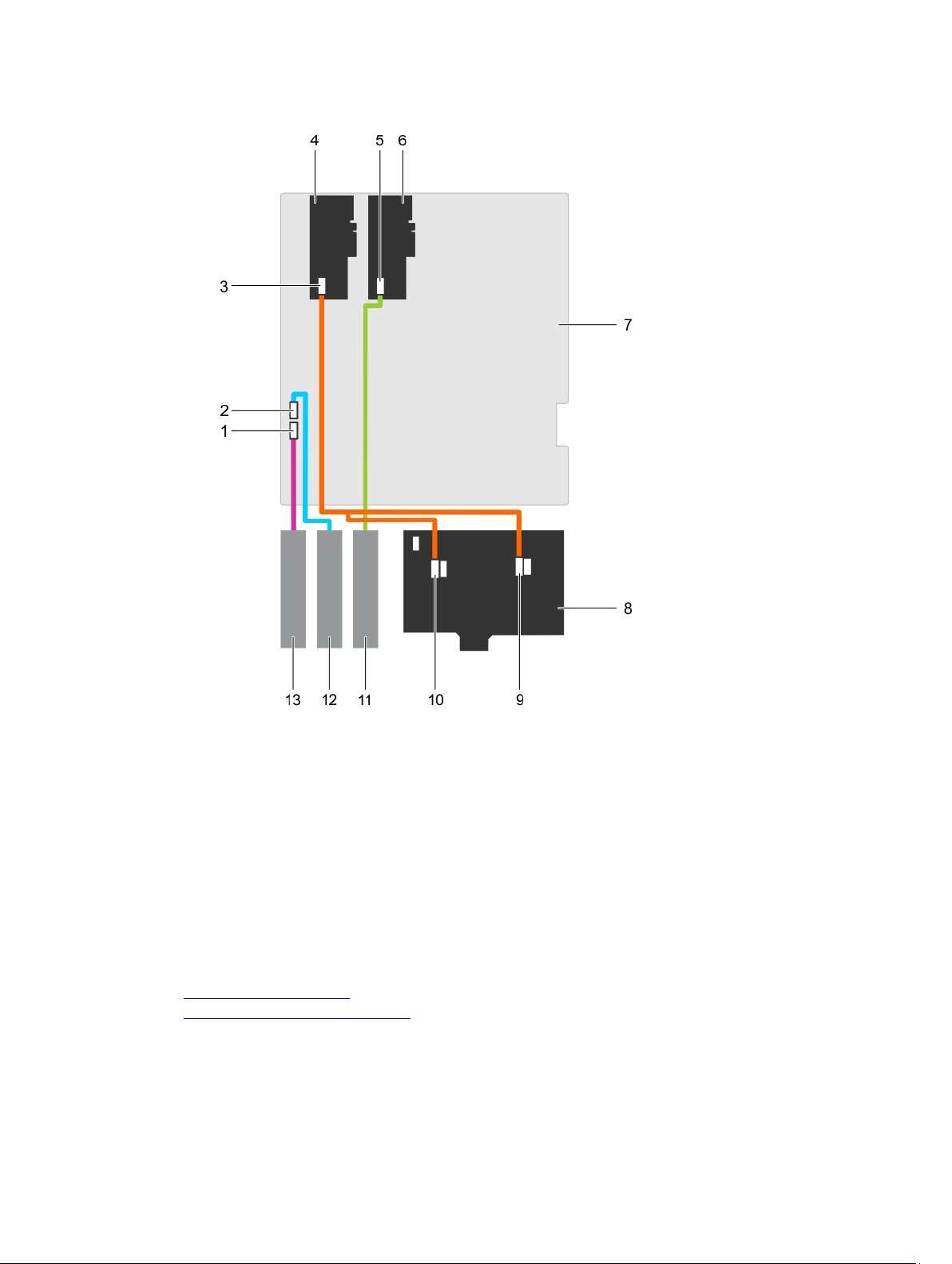
Figure 32. Cabling—x8 hard-drive backplane with two PERC cards
1. SATA optical drive connector on system
board
3. SAS connector on PERC card 4. PERC card
5. SAS connector on PERC card 6. PERC card
7. system board 8. x8 backplane
9. SAS B connector on backplane 10. SAS A connector on backplane
11. SAS tape drive 12. SATA tape drive
13. optical drive
Related Links
Removing the front bezel
Installing the hard-drive backplane
2. SATA tape drive connector on system
board
81
Page 82

Installing the hard-drive backplane
Prerequisites
CAUTION: Many repairs may only be done by a certified service technician. You should only
perform troubleshooting and simple repairs as authorized in your product documentation, or as
directed by the online or telephone service and support team. Damage due to servicing that is
not authorized by Dell is not covered by your warranty. Read and follow the safety instructions
that came with the product.
Ensure that you read the Safety instructions.
Steps
1. Use the hooks at the back of the hard-drive bay as guides to align the hard-drive backplane.
2. Slide down the hard-drive backplane until the release pin locks into the slot.
3. Connect the SAS, power, signal, and I2C cables to the hard-drive backplane.
Next steps
1. Install the hard drives in their original locations.
2. Follow the procedure listed in After working inside your system.
Related Links
Removing the hard-drive backplane
Four-slot hard-drive blank
Systems with x8 hard-drive backplanes configured for software RAID support only four hard drives. The
remaining hard-drive slots are pre-installed with the four-slot hard-drive blank, and are not available for
software RAID.
Removing a four-slot hard-drive blank
Prerequisites
CAUTION: To maintain proper system cooling, all empty hard-drive slots must have hard-drive
blanks installed.
NOTE: This is a service only procedure.
1. Ensure that you read the Safety instructions.
2. Follow the procedure listed in Before working inside your system.
CAUTION: To prevent damage to the hard drives and backplane, you must remove the hard
drives from the system before removing the backplane.
CAUTION: Note the slot number of each hard drive and temporarily label the slots before
removing the hard drives so that you can replace them in the same location(s).
3. Remove all hard drives.
4. Remove the cooling shroud.
5. Remove the x8 hard-drive backplane.
82
Page 83
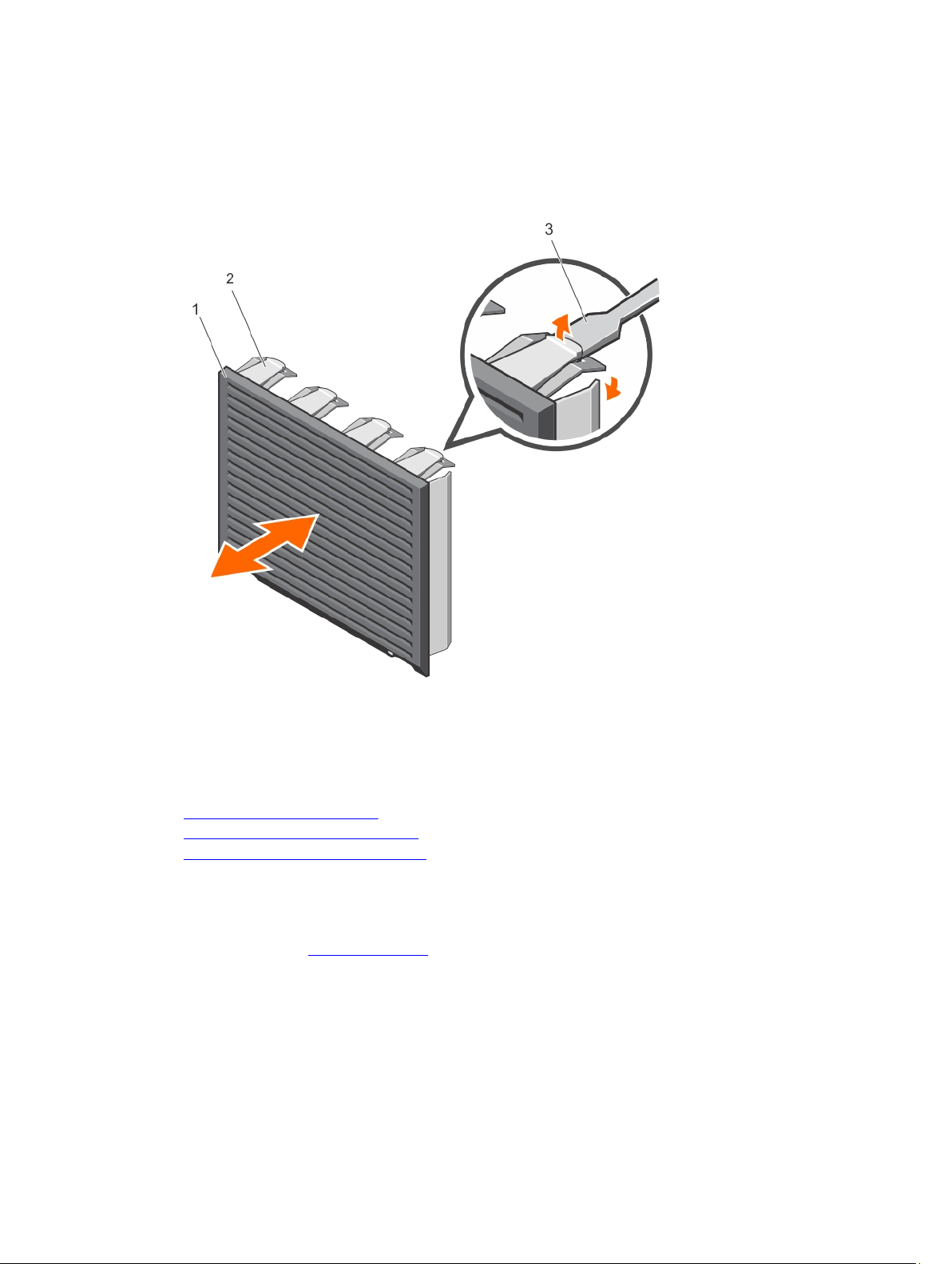
Steps
1. Using a screwdriver, push the release tabs on the four corners of the blank from inside the system, to
unlock the four-slot hard-drive blank from the chassis.
2. From the front of the system, pull the four-slot hard-drive blank at the corners until it is free of the
hard-drive slot.
Figure 33. Installing and removing the four-slot hard-drive blank
1. four-slot hard-drive blank 2. release tab
3. screwdriver
Related Links
Removing the cooling shroud
Removing the hard-drive backplane
Installing a four-slot hard-drive blank
Installing a four-slot hard-drive blank
Prerequisites
Ensure that you read the Safety instructions.
Steps
1. Locate the hard drive slots numbered from four to seven.
2. Insert the four-slot hard-drive blank into the hard-drive slot, and push it until the release tabs click
into place.
83
Page 84

Next steps
Follow the instructions listed in After working inside your system.
Related Links
Removing a four-slot hard-drive blank
System memory
Your system supports DDR4 registered DIMMs (RDIMMs). It supports DDR4 voltage specifications.
NOTE: MT/s indicates DIMM speed in MegaTransfers per second.
Memory bus operating frequency can be 2133 MT/s, 1866 MT/s, 1600 MT/s, or 1333 MT/s depending on:
• System profile selected (for example, Performance Optimized, Custom, or Dense Configuration
Optimized)
• Maximum supported DIMM frequency of the processors
Your system contains 12 memory sockets split into four sets— two sets of 4 sockets and two sets of 2
sockets each. DIMMs in sockets A1 to A8 are assigned to processor 1 and DIMMs in sockets B1 to B4 are
assigned to processor 2. Each 4-socket set is organized into two channels and each 2–socket set is
organized into one channel. In each channel of the 4-socket set, the release levers of the first socket are
marked white and those of the second socket are marked black. In the 2-socket set, each release lever is
marked white.
84
Page 85
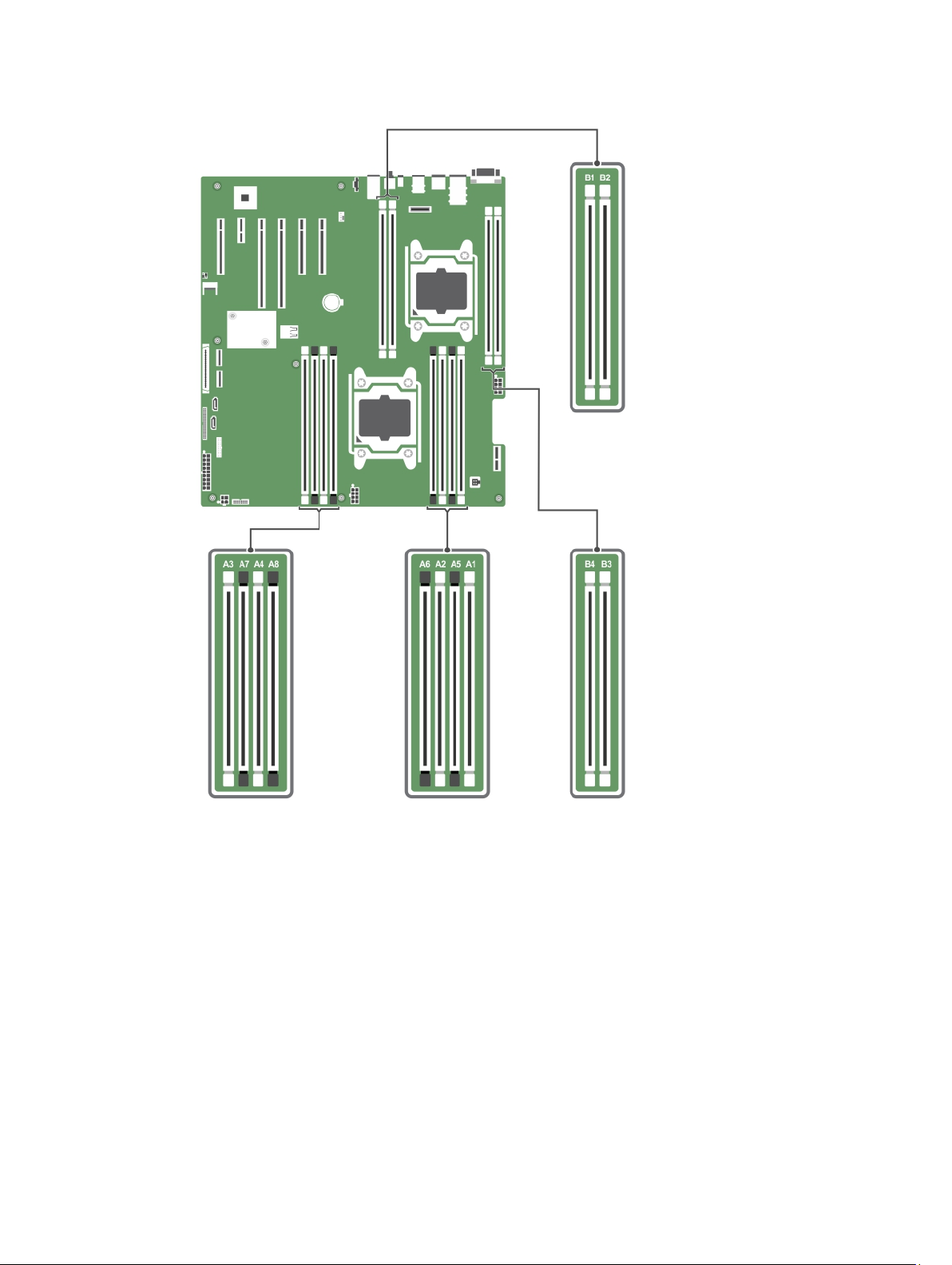
Figure 34. Memory socket locations
Memory channels are organized as follows:
Processor 1 channel 0: slots A1 and A5
channel 1: slots A2 and A6
channel 2: slots A3 and A7
channel 3: slots A4 and A8
Processor 2 channel 0: slot B1
channel 1: slot B2
channel 2: slot B3
85
Page 86

channel 3: slot B4
The following table shows the memory populations and operating frequencies for the supported
configurations.
DIMM Type
RDIMM
DIMMs Populated/
Channel
1
2
Operating Frequency (in
MT/s)
1.2 V
2133, 1866, 1600, and 1333 Single rank or dual rank
Maximum DIMM Rank/Channel
General memory module installation guidelines
Your system supports Flexible Memory Configuration, enabling the system to be configured and run in
any valid chipset architectural configuration. The following are the recommended guidelines for installing
memory modules:
• x4 and x8 DRAM based DIMMs can be mixed. For more information, see Mode-specific guidelines.
• Up to two dual- or single-rank RDIMMs can be populated per channel.
• Populate DIMM sockets only if a processor is installed. For single-processor systems, sockets A1 to A8
are available. For dual-processor systems, sockets A1 to A8 and sockets B1 to B4 are available.
• Populate all sockets with white release levers first, and then all the sockets with black release levers.
• When mixing memory modules with different capacities, populate the sockets with memory modules
with highest capacity first. For example, if you want to mix 4 GB and 8 GB DIMMs, populate 8 GB
DIMMs in the sockets with white release levers and 4 GB DIMMs in the sockets with black release
levers.
• In a dual-processor configuration, the memory configuration for each processor should be identical
through the first eight slots. For example, if you populate socket A1 for processor 1, then populate
socket B1 for processor 2, and so on.
• Memory modules of different capacities can be mixed provided other memory population rules are
followed (for example, 4 GB and 8 GB memory modules can be mixed).
• Mixing of more than two DIMM capacities in a system is not supported.
• Populate two DIMMs per processor (one DIMM per channel) at a time to maximize performance.
Mode-specific guidelines
Four memory channels are allocated to each processor. The allowable configurations depend on the
memory mode selected.
NOTE: You can mix x4 and x8 DRAM based DIMMs to support RAS features. However, all guidelines
for specific RAS features must be followed. x4 DRAM based DIMMs retain Single Device Data
Correction (SDDC) in memory optimized (independent channel) mode. x8 DRAM based DIMMs
require Advanced ECC mode to gain SDDC.
The following sections provide additional slot population guidelines for each mode:
Advanced ECC (lockstep)
Advanced ECC mode extends SDDC from x4 DRAM based DIMMs to both x4 and x8 DRAMs. This
protects against single DRAM chip failures during normal operation.
Memory installation guidelines:
86
Page 87

• Memory modules must be identical in size, speed, and technology.
• DIMMs installed in memory sockets with white release levers must be identical and similar rule applies
for sockets with black release levers. This ensures that identical DIMMs are installed in matched pairs for example, A1 with A2, A3 with A4, A5 with A6, and so on.
NOTE: Advanced ECC with Mirroring is not supported.
Memory optimized (independent channel) mode
This mode supports SDDC only for memory modules that use x4 device width, and the mode does not
impose any specific slot population requirements.
Memory sparing
NOTE: To use memory sparing, this feature must be enabled in the System Setup.
In this mode, one rank per channel is reserved as a spare. If persistent correctable errors are detected on
a rank, the data from this rank is copied to the spare rank and the failed rank is disabled.
With memory sparing enabled, the system memory available to the operating system is reduced by one
rank per channel. For example, in a dual-processor configuration with sixteen 4 GB dual-rank DIMMs, the
available system memory is: 3/4 (ranks/channel) × 16 (DIMMs) × 4 GB = 48 GB, and not 16 (DIMMs) × 4
GB = 64 GB.
NOTE: Memory sparing does not offer protection against a multi-bit uncorrectable error.
NOTE: Both Advanced ECC/Lockstep and Optimizer modes support Memory Sparing.
Sample memory configurations
The following tables show sample memory configurations for one and two processor configurations that
follow the appropriate memory guidelines.
NOTE: 1R and 2R in the following tables indicate single- and dual-rank DIMMs respectively.
Table 1. Memory configurations—single processor
System
Capacity (in
GB)
4 4 1
8 4 2
16 4 4
DIMM Size
(in GB)
8 2
Number of
DIMMs
DIMM Rank,
Organization, and
Frequency
1R, x8, 2133 MT/s,
1R, x8, 1866 MT/s
1R, x8, 2133 MT/s,
1R, x8, 1866 MT/s
1R, x8, 2133 MT/s,
1R, x8, 1866 MT/s
2R, x8, 2133 MT/s,
2R, x8, 1866 MT/s
DIMM Slot Population
A1
A1, A2
A1, A2, A3, A4
A1, A2
87
Page 88

System
Capacity (in
DIMM Size
(in GB)
GB)
24 4 6
Number of
DIMMs
DIMM Rank,
Organization, and
Frequency
1R, x8, 2133 MT/s,
1R, x8, 1866 MT/s
DIMM Slot Population
A1, A2, A3, A4, A5, A6
48 8 6
96 16 6
128 16 8
192 32 6
Table 2. Memory configurations—two processors
System
Capacity (in
DIMM Size (in
GB)
Number of
DIMMs
GB)
16 4 4
2R, x8, 2133 MT/s,
2R, x8, 1866 MT/s
2R, x4, 2133 MT/s,
2R, x4, 1866 MT/s
2R, x4, 2133 MT/s,
2R, x4, 1866 MT/s,
RDIMM, 2R, x4, 2133
MT/s
RDIMM, 2R, x4, 1866
MT/s
DIMM Rank,
Organization, and
Frequency
1R, x8, 2133 MT/s,
1R, x8, 1866 MT/s
A1, A2, A3, A4, A5, A6
A1, A2, A3, A4, A5, A6
A1, A2, A3, A4, A5, A6, A7, A8
A1, A2, A3, A4, A5, A6
DIMM Slot Population
A1, A2, B1, B2
32 4 8
64 8 8
96 8 12
128 16 8
160 16 and 8 12
88
1R, x8, 2133 MT/s,
1R, x8, 1866 MT/s
2R, x8, 2133 MT/s,
2R, x8, 1866 MT/s
2R, x8, 2133 MT/s,
2R, x8, 1866 MT/s
2R, x4, 2133 MT/s,
2R, x4, 1866 MT/s
2R, x4, 2133 MT/s,
2R, x8, 2133 MT/s,
2R, x4, 1866 MT/s
A1, A2, A3, A4, B1, B2, B3, B4
A1, A2, A3, A4, B1, B2, B3, B4
A1, A2, A3, A4, A5, A6,A7,A8, B1,
B2, B3, B4
A1, A2, A3, A4, B1, B2, B3, B4
A1, A2, A3, A4, A5, A6,A7,A8, B1,
B2, B3, B4
Page 89
System
Capacity (in
GB)
DIMM Size (in
GB)
Number of
DIMMs
DIMM Rank,
Organization, and
Frequency
2R, x8, 1866 MT/s
DIMM Slot Population
NOTE: 16 GB DIMMs must
be installed in slots
numbered A1, A2, A3, A4,
B1, B2, B3, and B4 and 8
GB DIMMs must be
installed in slots A5, A6, A7,
and A8.
192 16 12
384 32 12
2R, x4, 2133 MT/s,
2R, x4, 1866 MT/s
RDIMM, 2R, x4, 2133
MT/s
RDIMM, 2R, x4, 1866
MT/s
A1, A2, A3, A4, A5, A6,A7,A8, B1,
B2, B3, B4
A1, A2, A3, A4, A5, A6,A7,A8, B1,
B2, B3, B4
Removing memory modules
Prerequisites
CAUTION: Many repairs may only be done by a certified service technician. You should only
perform troubleshooting and simple repairs as authorized in your product documentation, or as
directed by the online or telephone service and support team. Damage due to servicing that is
not authorized by Dell is not covered by your warranty. Read and follow the safety instructions
that came with the product.
1. Ensure that you read the Safety instructions.
2. Follow the procedure listed in Before working inside your system.
3. Remove the cooling shroud.
WARNING: The memory modules are hot to the touch for some time after the system has been
powered down. Allow time for the memory modules to cool before handling them. Handle the
memory modules by the card edges and avoid touching the components or metallic contacts on
the memory module.
Steps
1. Locate the appropriate memory module socket.
CAUTION: Handle each memory module only by the card edges, making sure not to touch
the middle of the memory module or metallic contacts.
2. To release the memory module from the socket, simultaneously press the ejectors on both ends of
the memory-module socket.
89
Page 90
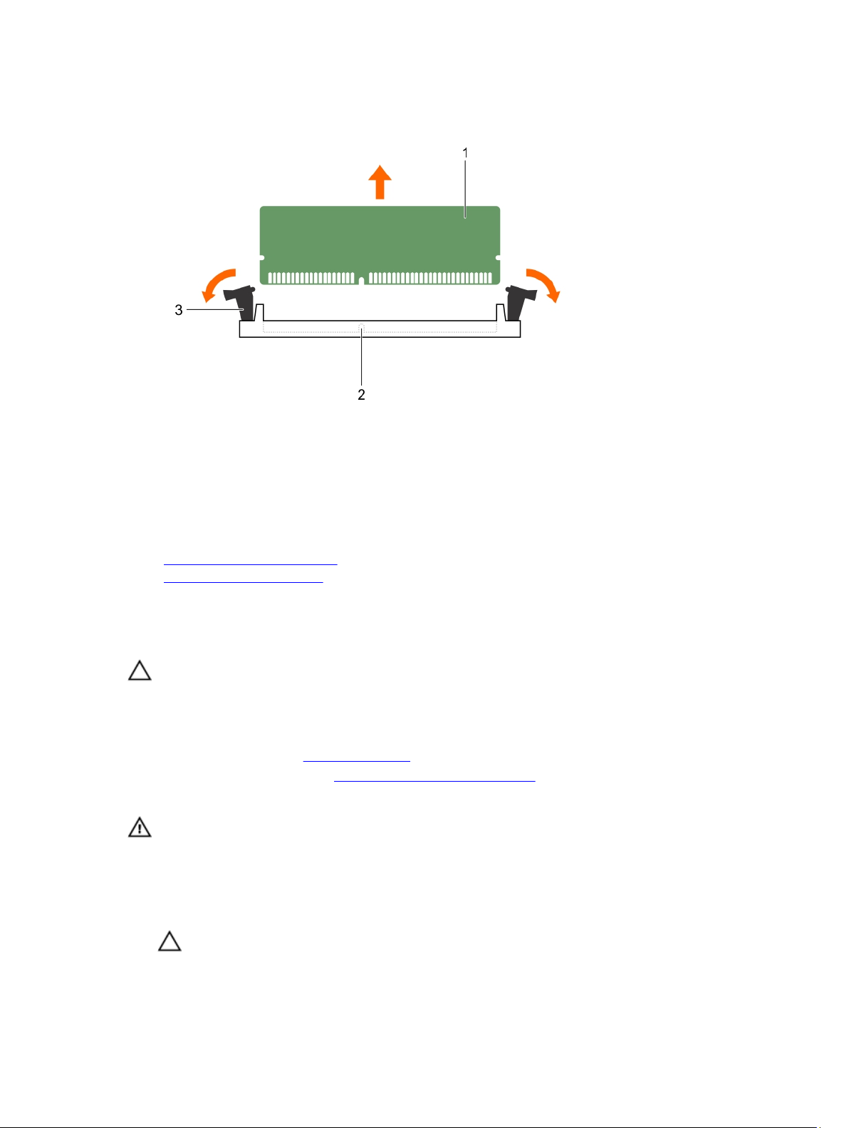
Figure 35. Removing and installing a memory module
1. memory module 2. memory-module socket
3. memory-module socket ejector (2)
Related Links
Removing the cooling shroud
Installing memory modules
Installing memory modules
Prerequisites
CAUTION: Many repairs may only be done by a certified service technician. You should only
perform troubleshooting and simple repairs as authorized in your product documentation, or as
directed by the online or telephone service and support team. Damage due to servicing that is
not authorized by Dell is not covered by your warranty. Read and follow the safety instructions
that came with the product.
1. Ensure that you read the Safety instructions.
2. Follow the procedure listed in Before working inside your system.
3. Remove the cooling shroud.
WARNING: The memory modules are hot to the touch for some time after the system has been
powered down. Allow time for the memory modules to cool before handling them. Handle the
memory modules by the card edges and avoid touching the components or metallic contacts on
the memory module.
Steps
1. Locate the appropriate memory-module socket.
CAUTION: Handle each memory module only by the card edges, making sure not to touch
the middle of the memory module or metallic contacts.
90
Page 91
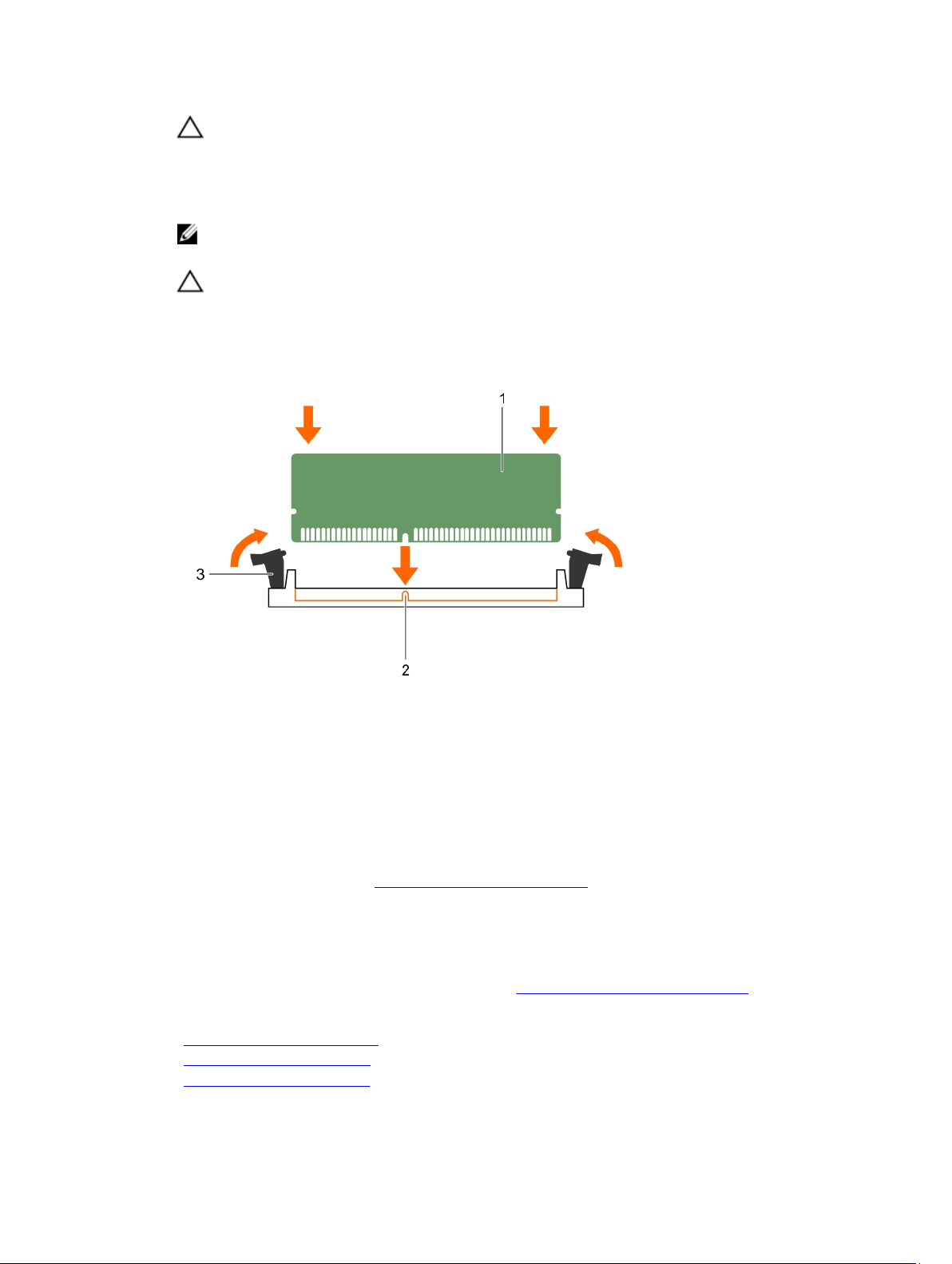
CAUTION: To prevent damage to the memory module or the memory-module socket during
installation, do not bend or flex the memory module; insert both ends of the memory module
simultaneously.
2. Align the edge connector of the memory module with the alignment key of the memory module
socket, and insert the memory module in the socket.
NOTE: The alignment key allows you to install the memory module in the socket in only one
way.
CAUTION: Do not apply pressure at the center of the memory module; apply pressure at both
ends of the memory module evenly.
3. Press the memory module with your thumbs until the socket levers firmly click into place.
Figure 36. Installing the memory module
1. memory module 2. alignment key
3. memory-module socket ejector (2)
Next steps
1. Install the cooling shroud.
2. Follow the procedure listed in After working inside your system.
3. Press <F2> to enter System Setup, and check the System Memory setting.
The system should have already changed the value to reflect the installed memory.
4. If the value is incorrect, one or more of the memory modules may not be installed properly. Ensure
that the memory modules are firmly seated in the sockets.
5. Run system memory test in system diagnostics. See Dell Embedded System Diagnostics.
Related Links
Removing the cooling shroud
Installing the cooling shroud
Removing memory modules
91
Page 92

Cooling fans
The system supports the following:
• An internal cooling fan
• An optional external cooling fan at the back of the chassis
NOTE: When selecting or upgrading your system configuration, verify the system power
consumption with the Dell Energy Smart Solution Advisor at dell.com/ESSA to ensure optimum
power utilization.
Removing the internal cooling fan
Prerequisites
CAUTION: Many repairs may only be done by a certified service technician. You should only
perform troubleshooting and simple repairs as authorized in your product documentation, or as
directed by the online or telephone service and support team. Damage due to servicing that is
not authorized by Dell is not covered by your warranty. Read and follow the safety instructions
that came with the product.
CAUTION: Never operate your system with the internal cooling fan removed. The system can
overheat and result in shutdown of the system and loss of data.
CAUTION: Do not operate the system with the cover removed for a duration exceeding 5
minutes.
1. Ensure that you read the Safety instructions.
2. Follow the procedure listed in Before working inside your system.
3. Remove the cooling shroud.
Steps
1. Disconnect the internal cooling fan power cable from the system board.
2. Press the release tab on the internal cooling fan, and holding the internal cooling fan by the sides,
slide it out in the direction of the arrow marked on the fan.
CAUTION: Do not remove or install the internal cooling fan by holding the fan blades.
92
Page 93
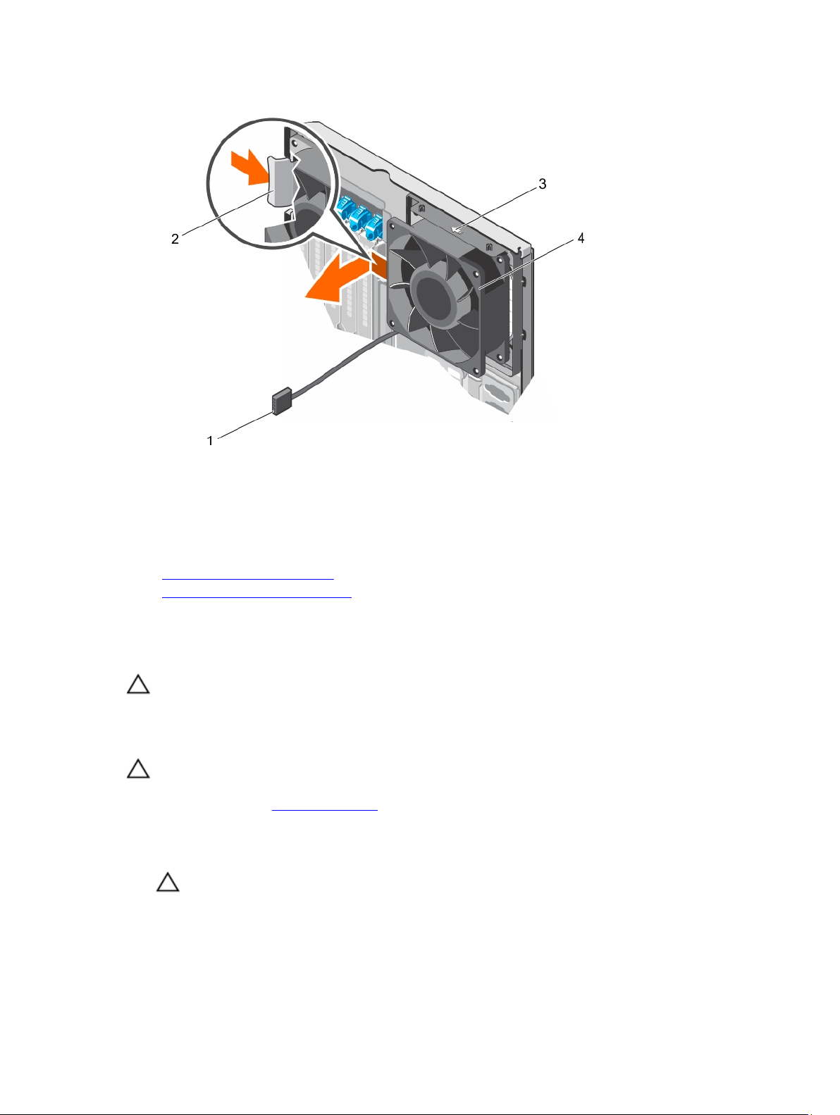
Figure 37. Removing and installing the internal cooling fan
1. internal cooling fan power cable 2. release tab
3. arrow 4. internal cooling fan
Related Links
Removing the cooling shroud
Installing the internal cooling fan
Installing the internal cooling fan
Prerequisites
CAUTION: Many repairs may only be done by a certified service technician. You should only
perform troubleshooting and simple repairs as authorized in your product documentation, or as
directed by the online or telephone service and support team. Damage due to servicing that is
not authorized by Dell is not covered by your warranty. Read and follow the safety instructions
that came with the product.
CAUTION: Do not operate the system with the cover removed for a duration exceeding 5
minutes.
Ensure that you read the Safety instructions.
Steps
1. Hold the cooling fan by the sides with the cable end facing the bottom of the chassis.
CAUTION: Do not remove or install the internal cooling fan by holding the fan blades.
2. Align the four tabs on the internal cooling fan with the four slots on the chassis wall.
3. Press and slide the internal cooling fan into the slots until the release tab locks into place.
93
Page 94

CAUTION: Do not remove or install the internal cooling fan by holding the blades.
4. Connect the internal cooling fan power cable to the FAN1 connector on the system board.
Next steps
1. Install the cooling shroud.
2. Follow the procedure listed in After working inside your system.
Related Links
Installing the cooling shroud
Removing the internal cooling fan
Removing the external cooling fan
Prerequisites
CAUTION: Many repairs may only be done by a certified service technician. You should only
perform troubleshooting and simple repairs as authorized in your product documentation, or as
directed by the online or telephone service and support team. Damage due to servicing that is
not authorized by Dell is not covered by your warranty. Read and follow the safety instructions
that came with the product.
1. Ensure that you read the Safety instructions.
2. Follow the procedure listed in Before working inside your system.
3. Remove the cooling shroud.
Steps
1. Disconnect the external cooling fan power cable from the system board.
2. Remove the four screws that secure the external cooling fan to the chassis.
3. Lift the external cooling fan to disengage the upper and the lower hooks from the slots on the
chassis wall and remove the cooling fan.
4. Remove the external cooling fan power cable from of the system through the external cooling fan
power cable slot at the back of the chassis.
94
Page 95
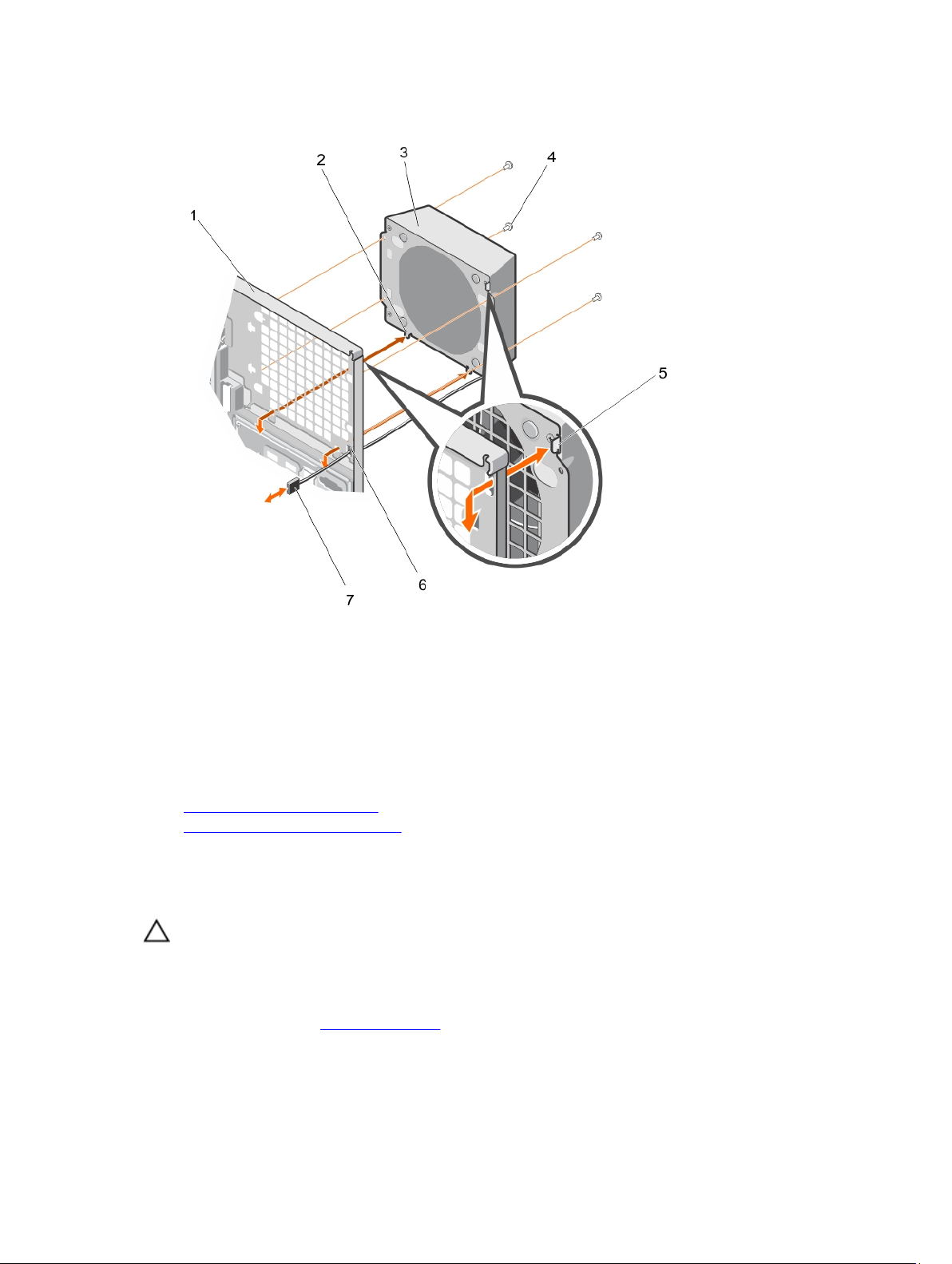
Figure 38. Removing and Installing the external cooling fan
1. back of the system chassis 2. bottom hook (2)
3. external cooling fan 4. screw (4)
5. upper hook 6. external cooling fan power cable slot
7. external cooling fan power cable
Related Links
Removing the cooling shroud
Installing the external cooling fan
Installing the external cooling fan
Prerequisites
CAUTION: Many repairs may only be done by a certified service technician. You should only
perform troubleshooting and simple repairs as authorized in your product documentation, or as
directed by the online or telephone service and support team. Damage due to servicing that is
not authorized by Dell is not covered by your warranty. Read and follow the safety instructions
that came with the product.
Ensure that you follow the Safety instructions.
95
Page 96

Steps
1. Route the external cooling fan power cable into the system through the external cooling fan power
cable slot at the back of the chassis.
2. Align and insert the lower and upper hooks on the external cooling fan into the corresponding slots
at the back of the chassis.
3. Use the four screws to secure the external cooling fan to the chassis.
4. Connect the external cooling fan power cable to the FAN2 connector on the system board.
Next steps
1. Install the cooling shroud.
2. Follow the procedure listed in After working inside your system.
Related Links
Installing the cooling shroud
Removing the external cooling fan
Internal USB memory key (optional)
An optional USB memory key installed inside your system can be used as a boot device, security key, or
mass storage device. The USB connector must be enabled by the Internal USB Port option in the
Integrated Devices screen of System Setup.
To boot from the USB memory key, configure the USB memory key with a boot image and then specify
the USB memory key in the boot sequence in System Setup.
NOTE: To locate the internal USB connector (INT_USB) on the system board, see System board
connectors.
Replacing the internal USB key
Prerequisites
CAUTION: Many repairs may only be done by a certified service technician. You should only
perform troubleshooting and simple repairs as authorized in your product documentation, or as
directed by the online or telephone service and support team. Damage due to servicing that is
not authorized by Dell is not covered by your warranty. Read and follow the safety instructions
that came with the product.
1. Ensure that you read the Safety instructions.
2. Follow the procedure listed in Before working inside your system.
Steps
1. Locate the USB connector/USB key on the system board.
NOTE: To locate the internal USB connector on the system board, see System board
connectors.
2. If installed, remove the USB key.
3. Insert the new USB key into the USB connector.
96
Page 97
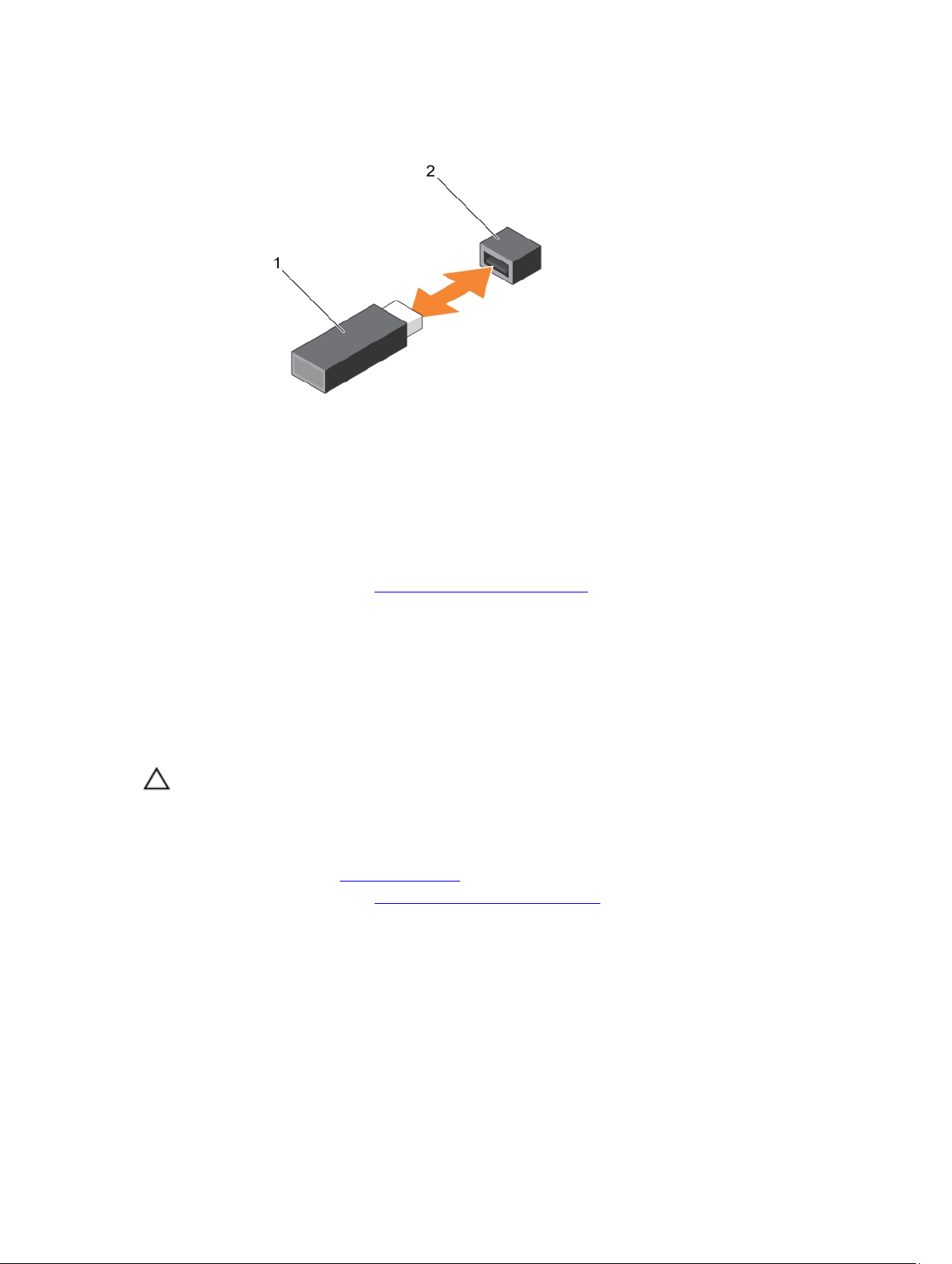
Figure 39. Replacing the internal USB key
1. USB memory key 2. USB memory key connector
Next steps
1. Follow the procedure listed in After working inside your system.
2. While booting, press <F2> to enter System Setup and verify that USB key is detected by the system.
Expansion card holder
Removing the expansion card holder
Prerequisites
CAUTION: Many repairs may only be done by a certified service technician. You should only
perform troubleshooting and simple repairs as authorized in your product documentation, or as
directed by the online or telephone service and support team. Damage due to servicing that is
not authorized by Dell is not covered by your warranty. Read and follow the safety instructions
that came with the product.
1. Ensure that you read the Safety instructions.
2. Follow the procedure listed in Before working inside your system.
Steps
Press the tab and remove the expansion-card holder from the chassis.
97
Page 98
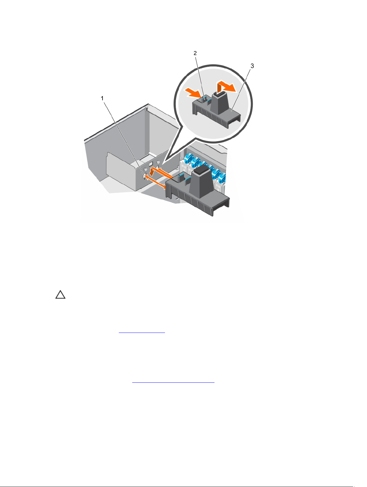
Figure 40. Removing and installing the expansion card holder
1. projection (2) 2. tab
3. expansion card holder
Installing the expansion card holder
Prerequisites
CAUTION: Many repairs may only be done by a certified service technician. You should only
perform troubleshooting and simple repairs as authorized in your product documentation, or as
directed by the online or telephone service and support team. Damage due to servicing that is
not authorized by Dell is not covered by your warranty. Read and follow the safety instructions
that came with the product.
Ensure that you read the Safety instructions.
Steps
Align the expansion card holder with the projections on the chassis and push it down until firmly
seated.
Next steps
Follow the procedure listed in After working inside your system.
Expansion cards
98
Page 99

Expansion card installation guidelines
Table 3. PCI Express Generation 3 expansion cards supported
PCIe Slot Processor Connection Height Length Link Width Slot Width
1 Platform Controller
Hub
2 Platform Controller
Hub
3 Processor 1 Full Height Full Length x16 x16
4 Processor 1 Full Height Full Length x16 x16
5 Processor 2 Full Height Half Length x8 x8
6 Processor 2 Full Height Half Length x8 x8
NOTE: Only slots 3, 4, 5, and 6 support Generation 3 PCIe expansion cards.
NOTE: Do not use slots 5 and 6 for single processor configuration (CPU1).
NOTE: When your system is installed with a double-width GPU card in slot 3, you cannot install an
expansion card in slot 2.
NOTE: When your system is installed with a double-width GPU card in slot 4, you cannot install an
expansion card in slot 3.
NOTE: The expansion cards are not hot-swappable.
The following table provides a guide for installing expansion cards to ensure proper cooling and
mechanical fit. The expansion cards with the highest priority must be installed first using the slot priority
indicated. All other expansion cards must be installed following the card priority and slot priority order.
Full Height Half Length x4 x8
Full Height Half Length x1 x1
Table 4. Expansion card installation order
Card Priority Card Type Slot Priority Maximum Allowed
1 GPU 4 1
GPU (AMD W7000) 3, 4 2
2 RAID 3, 4 2
RAID (H830) 3, 4, 5, 6 4
3 10 Gb NICs 3, 4, 5, 6, 1 5
4 FC8 HBA 3, 4, 5, 6, 1 5
5 1 Gb NICs 3, 4, 5, 6, 1 5
1 Gb NIC
(Broadcom Dual
Port)
6 Non-RAID 3, 4, 5, 6 4
3, 4, 5, 6, 1, 2 6
99
Page 100

GPU card installation guidelines
Observe the following guidelines while installing a GPU card:
• Ensure that all GPU cards are of the same type or model.
• Your system supports only Q4000 single-width GPU cards and Q6000 double-width GPU card.
• You can install one double-width or two single-width cards on slots 3 and 5 on a dual-processor
system.
• Systems with a double-width GPU card can support only one 5.25 inch removable media storage
device.
• GPU cards must be installed on a system with redundant 1100 W AC power supplies.
• Your system supports GPU cards of only 300 W or less.
Removing an expansion card
Prerequisites
CAUTION: Many repairs may only be done by a certified service technician. You should only
perform troubleshooting and simple repairs as authorized in your product documentation, or as
directed by the online or telephone service and support team. Damage due to servicing that is
not authorized by Dell is not covered by your warranty. Read and follow the safety instructions
that came with the product.
1. Ensure that you read the Safety instructions.
2. Follow the procedure listed in Before working inside your system.
3. Remove the expansion-card holder.
Steps
1. Disconnect the data cables from the PERC card and/or the power cables from the GPU card.
2. Open the expansion-card latch in the direction of the arrow shown in the following figure.
3. Hold the expansion card by its edge, pull the card up to remove it from the expansion-card slot and
out of the system.
4. Install the filler bracket by performing the following steps:
a. Align the tab on the filler bracket with the expansion card slot.
b. Press the expansion-card latch until the filler bracket locks into place.
NOTE: Filler brackets must be installed over empty expansion-card slots to maintain FCC
certification of the system. The brackets also keep dust and dirt out of the system and aid in
proper cooling and airflow inside the system.
100
 Loading...