

Dell E1200i ExaScale Installation Manual

E1200i ExaScale
Installation Guide

Notes, Cautions, and Warnings
NOTE: A NOTE indicates important information that helps you make better use of your computer.
CAUTION: A CAUTION indicates potential damage to hardware or loss of data if instructions are not
followed.
WARNING: A WARNING indicates a potential for property damage, personal injury, or death.
Information in this publication is subject to change without notice.
© 2010 Dell Force10. All rights reserved.
Reproduction of these materials in any manner whatsoever without the written permission of Dell Inc. is strictly forbidden.
Trademarks used in this text: Dell™, the DELL logo, Dell Precision™, OptiPlex™, Latitude™, PowerEdge™, PowerVault™,
PowerConnect™, OpenManage™, EqualLogic™, KACE™, FlexAddress™ and Vostro™ are trademarks of Dell Inc. Intel
®
Xeon
, Core™ and Celeron® are registered trademarks of Intel Corporation in the U.S. and other countries. AMD® is a registered trademark
and AMD Opteron™, AMD Phenom™, and AMD Sempron™ are trademarks of Advanced Micro Devices, Inc. Microsoft
Windows Server
States and/or other countries. Red Hat Enterprise Linux
and/or other countries. Novell
®
Oracle
is a registered trademark of Oracle Corporation and/or its affiliates. Citrix®, Xen®, XenServer® and XenMotion® are either registered
trademarks or trademarks of Citrix Systems, Inc. in the United States and/or other countries. VMware
and vSphere
®
, MS-DOS® and Windows Vista® are either trademarks or registered trademarks of Microsoft Corporation in the United
®
is a registered trademark and SUSE ™ is a trademark of Novell Inc. in the United States and other countries.
®
are registered trademarks or trademarks of VMWare, Inc. in the United States or other countries.
Other trademarks and trade names may be used in this publication to refer to either the entities claiming the marks and names or their products.
Dell Inc. disclaims any proprietary interest in trademarks and trade names other than its own.
November 2011 P/N 100-00069-04
®
, Pentium®,
®
, Windows®,
®
and Enterprise Linux® are registered trademarks of Red Hat, Inc. in the United States
®
, Virtual SMP®, vMotion®, vCenter®,

Contents
1 About This Guide
Information Symbols and Warnings . . . . . . . . . . . . . . . . . . . . . . . . . . . . . . . . . . . . . . 7
Related Publications . . . . . . . . . . . . . . . . . . . . . . . . . . . . . . . . . . . . . . . . . . . . . . . . . . 8
2 The E1200 System
Operating Overview . . . . . . . . . . . . . . . . . . . . . . . . . . . . . . . . . . . . . . . . . . . . . . . . . . 9
3 Site Preparation
Site Selection Criteria . . . . . . . . . . . . . . . . . . . . . . . . . . . . . . . . . . . . . . . . . . . . . . . . 15
Rack Mounting . . . . . . . . . . . . . . . . . . . . . . . . . . . . . . . . . . . . . . . . . . . . . . . . . . . . . 16
Cabinet Placement . . . . . . . . . . . . . . . . . . . . . . . . . . . . . . . . . . . . . . . . . . . . . . . . . . 16
Power . . . . . . . . . . . . . . . . . . . . . . . . . . . . . . . . . . . . . . . . . . . . . . . . . . . . . . . . . . . . 16
Fans and Airflow . . . . . . . . . . . . . . . . . . . . . . . . . . . . . . . . . . . . . . . . . . . . . . . . . . . . 17
Storing Components . . . . . . . . . . . . . . . . . . . . . . . . . . . . . . . . . . . . . . . . . . . . . . . . . 17
4 Installing the AC Chassis
Unpacking the E1200 System. . . . . . . . . . . . . . . . . . . . . . . . . . . . . . . . . . . . . . . . . . 19
Installing the Equipment Rack Shelf Bar. . . . . . . . . . . . . . . . . . . . . . . . . . . . . . . . . . 20
Standard Front Chassis Mounting. . . . . . . . . . . . . . . . . . . . . . . . . . . . . . . . . . . . . . . 20
Installing the Chassis into an Equipment Cabinet. . . . . . . . . . . . . . . . . . . . . . . . . . . 22
5 Installing the DC Chassis
Unpacking the E1200 System. . . . . . . . . . . . . . . . . . . . . . . . . . . . . . . . . . . . . . . . . . 23
Installing the Equipment Rack Shelf Bar. . . . . . . . . . . . . . . . . . . . . . . . . . . . . . . . . . 24
Standard Front Chassis Mounting. . . . . . . . . . . . . . . . . . . . . . . . . . . . . . . . . . . . . . . 24
Installing the Chassis into an Equipment Cabinet. . . . . . . . . . . . . . . . . . . . . . . . . . . 26
6 Installing Fan Trays
7 Installing AC Power Supplies
Securing the Chassis Ground. . . . . . . . . . . . . . . . . . . . . . . . . . . . . . . . . . . . . . . . . . 30
Installing Power Supplies . . . . . . . . . . . . . . . . . . . . . . . . . . . . . . . . . . . . . . . . . . . . . 30
AC Power Supply and Fan Operability Test . . . . . . . . . . . . . . . . . . . . . . . . . . . . . . . 31
8 Installing DC Power Supplies
Cable and Connector Requirements . . . . . . . . . . . . . . . . . . . . . . . . . . . . . . . . . 36
Installing DC PEMs . . . . . . . . . . . . . . . . . . . . . . . . . . . . . . . . . . . . . . . . . . . . . . 36
DC Power Supply and Fan Operability Test . . . . . . . . . . . . . . . . . . . . . . . . . . . . . . 40
Contents | 3

9 Installing RPMs, Line Cards, and SFM3s
Unpacking an RPM or Line Card . . . . . . . . . . . . . . . . . . . . . . . . . . . . . . . . . . . . . . . 43
Important Points to Remember . . . . . . . . . . . . . . . . . . . . . . . . . . . . . . . . . . . . . 43
Installing Line Cards and RPMs . . . . . . . . . . . . . . . . . . . . . . . . . . . . . . . . . . . . . . . . 43
RPMs. . . . . . . . . . . . . . . . . . . . . . . . . . . . . . . . . . . . . . . . . . . . . . . . . . . . . . . . . 44
Line Cards . . . . . . . . . . . . . . . . . . . . . . . . . . . . . . . . . . . . . . . . . . . . . . . . . . . . . 44
Blank Panels . . . . . . . . . . . . . . . . . . . . . . . . . . . . . . . . . . . . . . . . . . . . . . . . . . . 45
Preparing and Installing RPMs and Line Cards . . . . . . . . . . . . . . . . . . . . . . . . . . . . 45
Installing a Second RPM . . . . . . . . . . . . . . . . . . . . . . . . . . . . . . . . . . . . . . . . . . 47
RPM Label and LEDs . . . . . . . . . . . . . . . . . . . . . . . . . . . . . . . . . . . . . . . . . . . . . . . . 47
www.dell.com | support.dell.com
Line Card LEDs. . . . . . . . . . . . . . . . . . . . . . . . . . . . . . . . . . . . . . . . . . . . . . . . . . . . . 48
Installing Switch Fabric Modules (SFM3s) . . . . . . . . . . . . . . . . . . . . . . . . . . . . . . . . 48
SFM3 Front Panel and LEDs. . . . . . . . . . . . . . . . . . . . . . . . . . . . . . . . . . . . . . . 49
Line Card Cable Management Systems . . . . . . . . . . . . . . . . . . . . . . . . . . . . . . . . . . 49
10 RPM Ports and Cables
RPM Ports. . . . . . . . . . . . . . . . . . . . . . . . . . . . . . . . . . . . . . . . . . . . . . . . . . . . . . . . . 51
Connecting the Console and Auxiliary Ports . . . . . . . . . . . . . . . . . . . . . . . . . . . 51
Cable and Adapter Pin Assignments . . . . . . . . . . . . . . . . . . . . . . . . . . . . . . . . . . . . 52
Accessing the Console with a DB-9 Adapter. . . . . . . . . . . . . . . . . . . . . . . . . . . 53
Accessing the Console with a DB-25 Adapter. . . . . . . . . . . . . . . . . . . . . . . . . . 53
Accessing the Auxiliary Port by Modem. . . . . . . . . . . . . . . . . . . . . . . . . . . . . . . 54
Accessing the 10/100 Ethernet Management Port . . . . . . . . . . . . . . . . . . . . . . . . . . 54
Universal Serial Bus Ports . . . . . . . . . . . . . . . . . . . . . . . . . . . . . . . . . . . . . . . . . . . . 54
4 | Contents
11 Powering Up
Preparation . . . . . . . . . . . . . . . . . . . . . . . . . . . . . . . . . . . . . . . . . . . . . . . . . . . . . . . . 55
Supplying Power - AC. . . . . . . . . . . . . . . . . . . . . . . . . . . . . . . . . . . . . . . . . . . . . . . . 56
Supplying Power - DC. . . . . . . . . . . . . . . . . . . . . . . . . . . . . . . . . . . . . . . . . . . . . . . . 56
Booting to the CLI Prompt. . . . . . . . . . . . . . . . . . . . . . . . . . . . . . . . . . . . . . . . . . . . . 56
Booting from the BOOT_USER Prompt. . . . . . . . . . . . . . . . . . . . . . . . . . . . . . . 57
12 Removing and Replacing Components
Removing and Replacing Fan Trays. . . . . . . . . . . . . . . . . . . . . . . . . . . . . . . . . . . . . 59
Removing and Replacing AC Power Supplies . . . . . . . . . . . . . . . . . . . . . . . . . . . . . 60
Remove an AC Power Supply in a non-redundant installation. . . . . . . . . . . . . 61
Remove an AC Power Supply in a redundant installation . . . . . . . . . . . . . . . . . 61
Removing and Replacing DC Power Supplies . . . . . . . . . . . . . . . . . . . . . . . . . . . . . 61
Remove a DC Power Supply. . . . . . . . . . . . . . . . . . . . . . . . . . . . . . . . . . . . . . . 62
Removing and Replacing RPMs, Line Cards, or SFM3s . . . . . . . . . . . . . . . . . . . . . 63

Removing and Replacing line cards or RPMs . . . . . . . . . . . . . . . . . . . . . . . . . . 63
Removing and Replacing SFM3s . . . . . . . . . . . . . . . . . . . . . . . . . . . . . . . . . . . 64
Removing and Replacing the Air Filter . . . . . . . . . . . . . . . . . . . . . . . . . . . . . . . . . . . 65
13 Using a Flash Memory Card
External Flash Memory Card . . . . . . . . . . . . . . . . . . . . . . . . . . . . . . . . . . . . . . . . . . 67
Inserting the External Flash Memory Card . . . . . . . . . . . . . . . . . . . . . . . . . . . . 67
Removing the External Flash Memory Card . . . . . . . . . . . . . . . . . . . . . . . . . . . 68
Formatting an External Flash Card . . . . . . . . . . . . . . . . . . . . . . . . . . . . . . . . . . 68
Copying Files to the External Flash. . . . . . . . . . . . . . . . . . . . . . . . . . . . . . . . . . 69
Displaying Files Stored on the External Flash. . . . . . . . . . . . . . . . . . . . . . . . . . 69
A System Boot
The System Boot Process. . . . . . . . . . . . . . . . . . . . . . . . . . . . . . . . . . . . . . . . . . . . . 71
System Boot . . . . . . . . . . . . . . . . . . . . . . . . . . . . . . . . . . . . . . . . . . . . . . . . . . . . . . . 71
Booting from the BOOT_USER Prompt . . . . . . . . . . . . . . . . . . . . . . . . . . . . . . . . . . 71
B Alarms
Power Supplies Alarms. . . . . . . . . . . . . . . . . . . . . . . . . . . . . . . . . . . . . . . . . . . . . . . 78
AC Power Supplies and Alarms . . . . . . . . . . . . . . . . . . . . . . . . . . . . . . . . . . . . . . . . 78
SFM3s and Alarms . . . . . . . . . . . . . . . . . . . . . . . . . . . . . . . . . . . . . . . . . . . . . . . . . . 79
C System Specifications
E1200i AC Chassis Physical Design . . . . . . . . . . . . . . . . . . . . . . . . . . . . . . . . . . . . 81
E1200i AC System Power Requirements . . . . . . . . . . . . . . . . . . . . . . . . . . . . . . . . . 82
E1200i DC Chassis Physical Design . . . . . . . . . . . . . . . . . . . . . . . . . . . . . . . . . . . . 82
E1200i DC System Power Requirements. . . . . . . . . . . . . . . . . . . . . . . . . . . . . . . . . 82
Environmental Specifications . . . . . . . . . . . . . . . . . . . . . . . . . . . . . . . . . . . . . . . . . . 83
Agency Compliance . . . . . . . . . . . . . . . . . . . . . . . . . . . . . . . . . . . . . . . . . . . . . . . . . 83
Safety Standards and Compliance Agency Certifications . . . . . . . . . . . . . . . . . 85
Electromagnetic Emissions . . . . . . . . . . . . . . . . . . . . . . . . . . . . . . . . . . . . . . . . 85
Immunity . . . . . . . . . . . . . . . . . . . . . . . . . . . . . . . . . . . . . . . . . . . . . . . . . . . . . . 85
Product Recycling and Disposal . . . . . . . . . . . . . . . . . . . . . . . . . . . . . . . . . . . . 86
D Technical Support
The iSupport Website . . . . . . . . . . . . . . . . . . . . . . . . . . . . . . . . . . . . . . . . . . . . . . . . 87
Accessing iSupport Services . . . . . . . . . . . . . . . . . . . . . . . . . . . . . . . . . . . . . . . 87
Contacting the Technical Assistance Center . . . . . . . . . . . . . . . . . . . . . . . . . . . . . . 88
Requesting a Hardware Replacement . . . . . . . . . . . . . . . . . . . . . . . . . . . . . . . . . . . 89
Contents | 5

www.dell.com | support.dell.com
6 | Contents
1
About This Guide
This guide provides site preparation recommendations, step-by-step procedures to rack mount the
Force10 Networks E1200 ExaScale chassis, as well as instructions to install its fan trays, power supplies,
route processor modules (RPMs), switch fabric modules (SFM3s), and line cards.
The E1200 system is packaged with components necessary for optimal performance, including blank
panels for RPM, SFM3, and line card slots. Blanks are required in empty slots to ensure adequate system
cooling and for EMI containment during operation.
E1200i systems run Dell Force10 OS (FTOS™) software. After you complete the hardware installation
process and power up the system, refer to the
information and the FTOS Command Reference for detailed CLI information.
Information Symbols and Warnings
FTOS Configuration Guide for software configuration
Table 1-1
Table 1-1. Information Symbols
Symbol Warning Description
defines the information symbols used throughout this guide.
Note This symbol informs you of important operational information.
Caution This symbol informs you that improper handling and installation could result in equipment
damage or loss of data.
Warning This symbol signals information about hardware handling that could result in injury.
WARNING: The installation of this equipment shall be performed by trained and qualified personnel only.
Read this guide before installing and powering up this equipment. This equipment contains two power cords.
Disconnect both power cords before servicing.
WARNING: This equipment contains optical transceivers, which comply with the limits of Class 1 laser
radiation.
WARNING: Visible and invisible laser radiation may be emitted from the aperture of the optical transceiver
ports when no cable is connected. Avoid exposure to laser radiation and do not stare into open apertures.
CAUTION: Wear grounding wrist straps when handling this equipment to avoid ESD damage.
About This Guide | 7

WARNING: Leakage Current (High Touch Current) in AC-powered systems: AC power cords are secured to
the power inlet using the provided brackets. The power cord plugs must be secured to the building outlets by
the qualified chassis installer or a qualified electrician.
See
Chapter 3, Site Preparation
for more cautions.
Related Publications
For more information about the E1200 system, refer to the following documents:
• FTOS Configuration Guide
• FTOS Command Reference
• FTOS Release Notes for the E-Series ExaScale
www.dell.com | support.dell.com
8 | About This Guide

2
The E1200 System
The Dell Force10 E1200 system is a carrier-class, high-capacity aggregation router. The 16-slot modular
system provides two slots dedicated for Route Processor Modules (RPMs) and 14 slots for line cards with
Layer 2 switching and Layer 3 and routing capabilities.
Operating Overview
The E1200 system requires a Route Processor Module (RPM), at least one line card, and at least eight
Switch Fabric Modules (SFM3s) for packet processing. The RPM is the core for routing and control
operations; all traffic destined for the E1200i terminates on the RPM. Routing table entries are built on
the RPM and directed to the forwarding information tables on the line cards.
Software processes, such as Telnet, SNMP, CLI, Layer 2, and Layer 3 functions, are divided among three
CPUs for redundancy and speed. Independent software images run on each CPU. Each CPU has its own
memory, which isolates processes from each other, increasing reliability. Operating the E1200 system
with redundant RPMs enables automatic fail-over redundancy.
Line cards perform all data forwarding operations. Each line card has at least one Force10 Networks
proprietary ASIC. The FPC accepts packets, feeds packets to input/output ports, handles packet
classification (access lists, and Layer 2 and Layer 3 lookups), and packet-marking (Diffserv or 802.1p).
The BTM is responsible for all queuing operations.
The internal flash memory device shipped with the RPM contains the boot ROM and runtime images.
Each RPM accommodates an external flash memory card and two USB ports that can be used to copy and
store system boot, software images, and configuration files. For information about using a flash card or
USB ports, refer to
Chapter 13, Using a Flash Memory Card
.
The E1200 System | 9
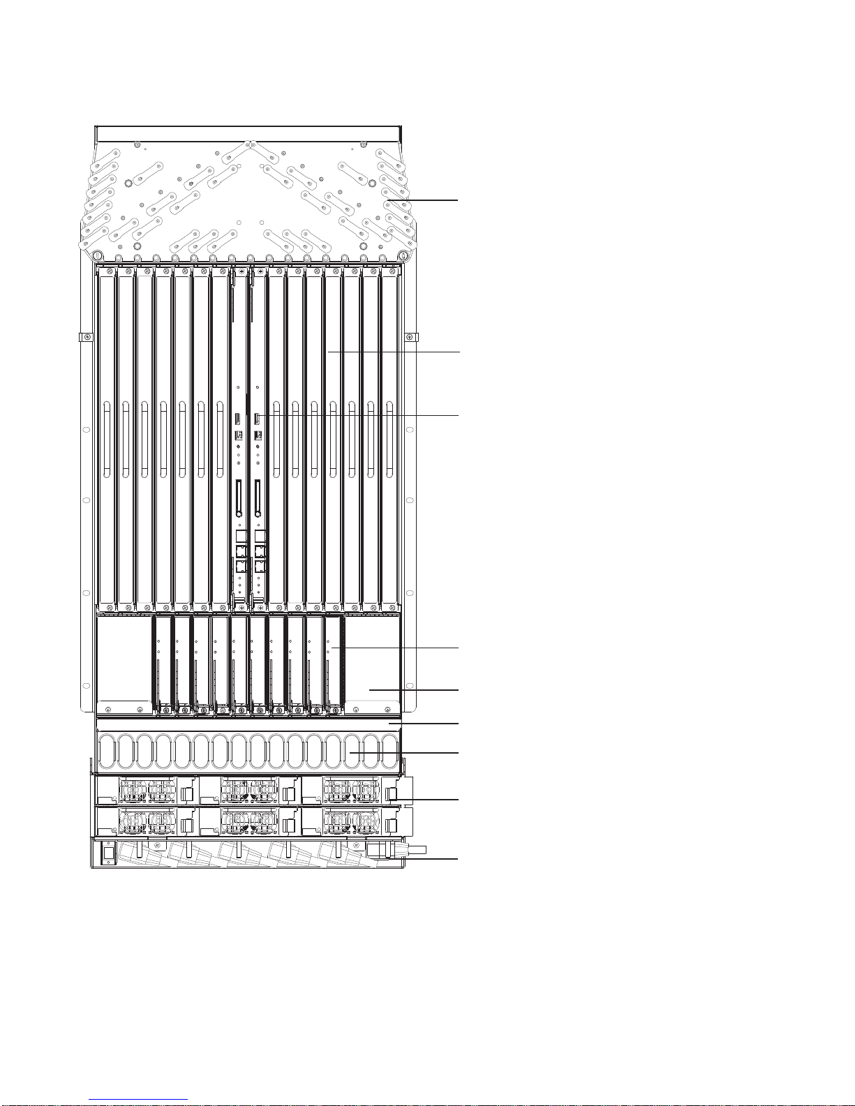
Figure 2-1. E1200i AC Chassis Front View
Cable Management
System
www.dell.com | support.dell.com
Line Card Slots
RPMs
Switch Fabric
Modules (SFM3s)
Blanks (BLNK)
Air Filter
10 | The E1200 System
Air Vents
AC Power Supplies
AC Power Plugs
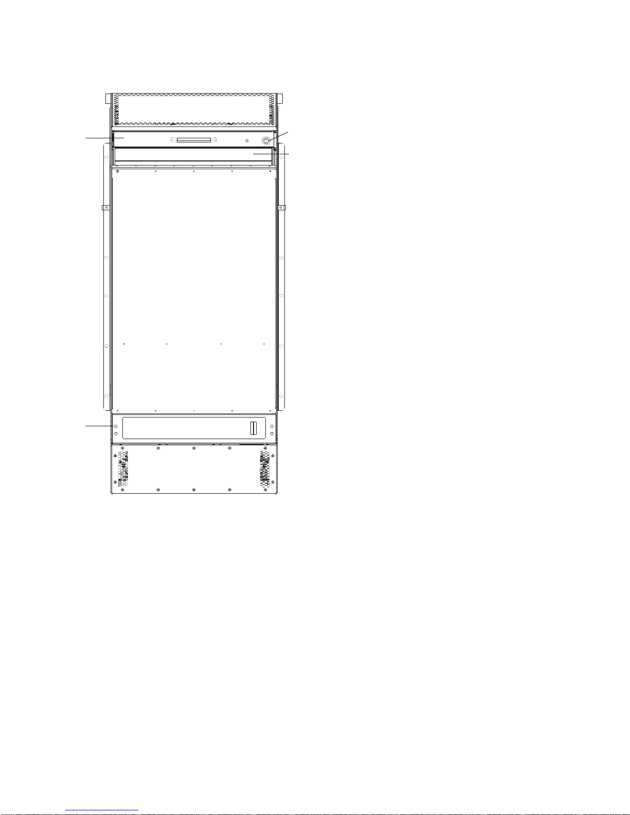
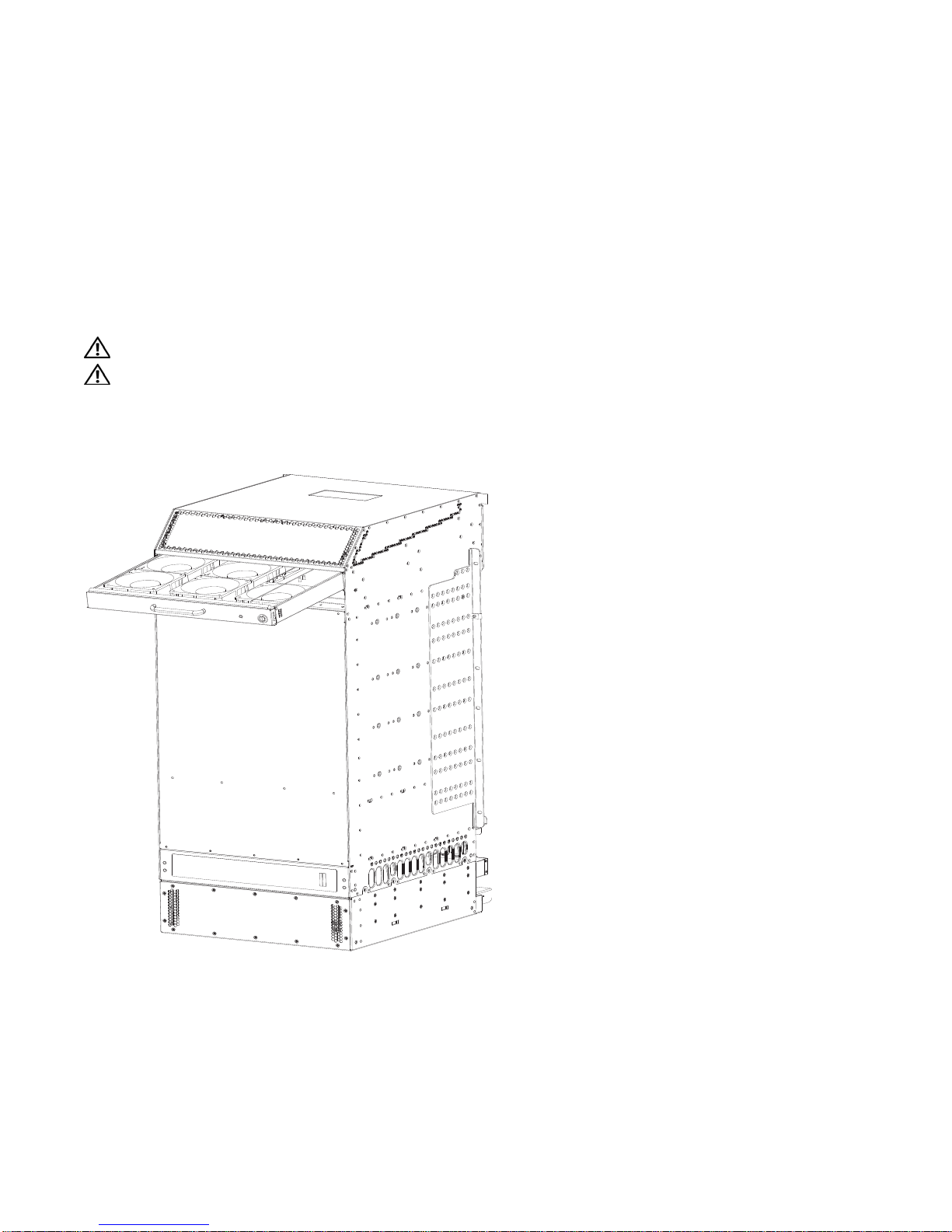
Figure 2-2. E1200 AC Chassis Rear View
Installed
Fan Tray
Locking
Screw
Empty Fan Tray
(with self-closing door)
Ground
Connection
The E1200 System | 11
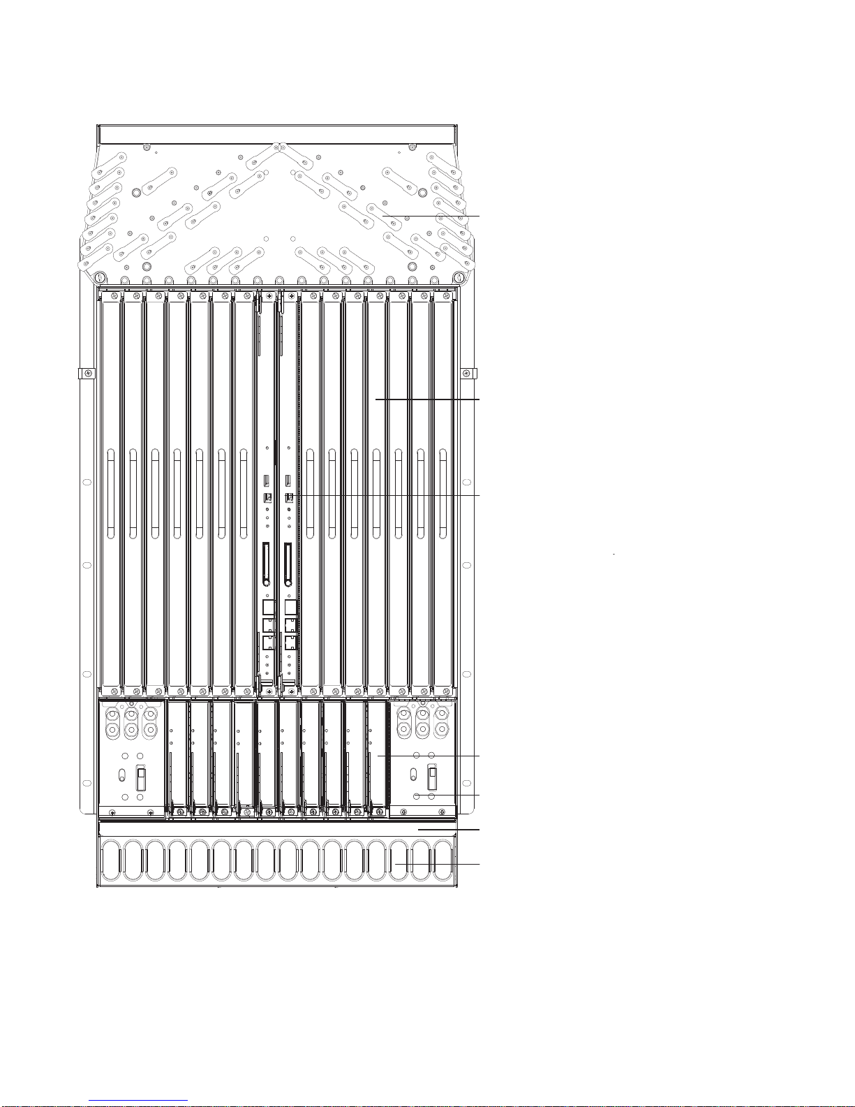
Figure 2-3. E1200i DC Chassis Front View
www.dell.com | support.dell.com
Cable Management
System
Line Card
Slots
RPMs
12 | The E1200 System
Switch Fabric
Modules (SFM3s)
DC Power Supply
Air Filter
Air Vents
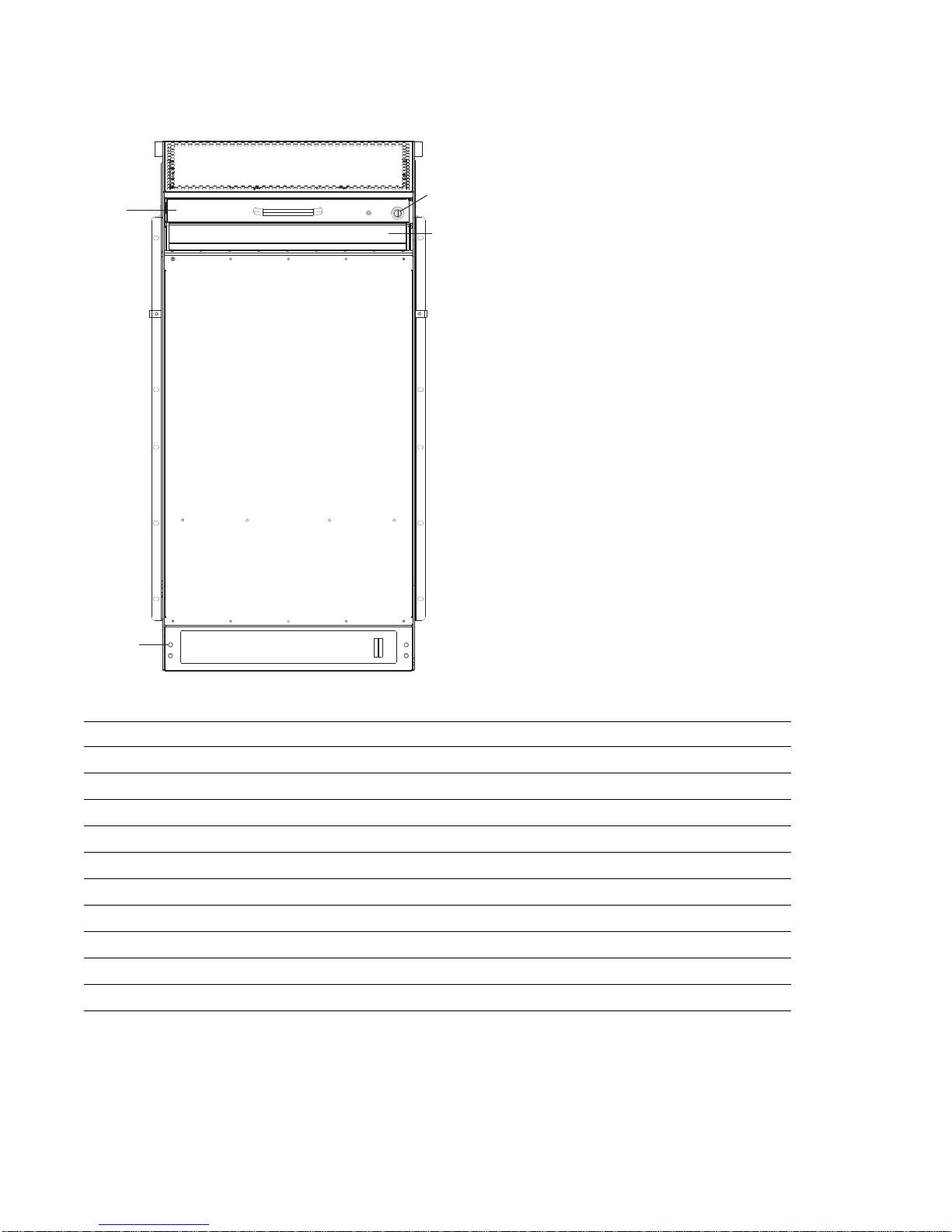
Figure 2-4. E1200 DC Chassis Rear View
Installed
Fan Tray
Locking
Screw
Empty Fan Tray
(with self-closing door)
Ground
Connection
Table 2-1. E1200 Hardware Component Operating Requirements Summary
Component Minimum Maximum Field-Replaceable
Backplane (factory installed) 1 1 N
Air filter (factory installed) 1 1 Y
Fan trays 2 2 Y
RPMs 1 2 Y
Line cards 1 14 Y
SFM3s 8 10 Y
AC Power Supply 3 (in a shelf) 6 Y
DC Power Supply 1 2 Y
Cable management system 0 1 Y
Cable management system cover 0 1 Y
The E1200 System | 13

To install the E1200 system:
Step Task Section
1 Prepare the site
Site Preparation
2 Unpack the AC chassis and components
Unpacking the E1200 System
or
Unpack the DC chassis and components
3 Mount the AC chassis
Unpacking the E1200 System
Standard Front Chassis Mounting
Installing the Chassis into an Equipment Cabinet
or
www.dell.com | support.dell.com
Mount the DC chassis
Standard Front Chassis Mounting
Installing the Chassis into an Equipment Cabinet
4 Install the cable management system See the instructions that come with the cable management system.
5 Install components:
• Fan trays
• Power Supplies (including power and
grounding cables)
6 Verify power supply and fan tray operability
Installing Fan Trays
Installing AC Power Supplies
Installing DC Power Supplies
AC Power Supply and Fan Operability Test
DC Power Supply and Fan Operability Test
7 Install card components:
• RPM(s) and line cards
• SFM3s
8 Connect network cable
9 Supply power to the chassis
Installing Line Cards and RPMs
Installing Switch Fabric Modules (SFM3s)
RPM Ports and Cables
Supplying Power - AC
Supplying Power - DC
10 Initial boot The initial boot operation automatically brings up the system to the
runtime CLI. To interrupt the automatic boot process, issue a break
key sequence (Ctrl^) if you experience boot problems.
The console monitor will display the default BOOT_USER # prompt.
Refer to
Chapter A, System Boot
for instructions to continue the boot
process.
14 | The E1200 System

3
Site Preparation
This chapter describes factors to consider before installing your E1200 system. The following topics are
discussed:
• Site Selection Criteria
• Rack Mounting
• Cabinet Placement
• Power
• Fans and Airflow
• Storing Components
For complete E1200 System Specifications, refer to
Chapter C, System Specifications
.
Site Selection Criteria
Before you begin the installation process, make sure that the area where you intend to install your E1200
meets the following safety requirements.
Select a site:
• In a restricted access area.
• In a dry, clean, well-ventilated and temperature-controlled room, away from nearby heat sources such as
hot air vents or direct sunlight.
• Away from sources of severe electromagnetic noise.
• Near an adequate power source. Connect the E1200 to the appropriate branch circuit protection as
defined by local electrical codes.
• Means of power disconnect must be located near the equipment.
• Position in a rack with adequate space in the front and rear, and sides of the unit for proper ventilation,
access to cables, and maintenance access. Allow
of the rack for ventilation. If placing the chassis in a cabinet, ensure that there is enough clearance
between the closed cabinet door and the cables in the cable management system on the chassis.
at least
18 inches in the front and 20 inches in the rear
• Ensure that the ambient temperature around the unit (which may be higher than the room temperature) is
within the limit specified for the unit.
• Ensure that there is sufficient airflow around the unit and that the electrical circuits are not overloaded.
Consider the nameplate rating of all the connected equipment, and ensure that there is over current
protection.
Site Preparation | 15

• Ensure that the equipment is properly grounded.
• Do not place objects on top of unit.
CAUTION: The E1200 AC shipping containers each weigh up to 400 pounds. The unpacked chassis and
pallet weigh approximately 200 pounds. Do not attempt to lift or move the chassis without the use of a hand
cart, pallet jack, or forklift.Lift the E1200 chassis either from the bottom or by the handles provided with the
front shipping cover. Lifting by the chassis shelves or fan tray openings will cause chassis damage. Do not
remove the protective front shipping cover until the chassis is secured in the equipment rack.
Rack Mounting
When you prepare your equipment rack, make sure the rack is bolted to the floor and/or braced to a wall
or ceiling.
www.dell.com | support.dell.com
When you install the chassis:
• Make sure that the rack is grounded to the grounding electrode. Each DC PEM must be grounded to the
rack or building ground bus. The equipment rack must be grounded to the same grounding electrode
used by the power service in your area. The ground path must be permanent.
• Install the E1200 chassis in the rack before you install internal components or make network and power
connections.
• In an empty rack, place the chassis in the lower half of the rack to ensure rack stability.
Cabinet Placement
The cabinet must meet the following criteria:
• Minimum cabinet size is 30 inches deep and 24 inches wide.
• Minimum air flow is 750 cubic feet per minute (CFM).
• Minimum of 3 inches between the closed doors and the front of the cable management panel, and a
minimum of 3 inches between the chassis rear and the rear of the cabinet with the cabinet door closed.
With the rear doors of the cabinet open, you will need a clearance of at least 20 inches from the rear to
access the chassis fan trays.
• Minimum of 20 inches clearance at the chassis front to access the air filter, power supplies, and cards.
Power
The E1200 requires 3 AC Power Supplies in a shelf (0, 1, 2 or 3, 4, 5) or 1 DC PEM to operate. For full
redundancy, you must have 6 AC Power Supplies (so that if one power supply fails in one shelf, the
system remains operational operates with the 3 power supplies in the other shelf) or a second 2 DC Power
Entry Module (2 total)
CAUTION: You cannot power the system with both types of power supply module installed. The system must
contain only one type of power module, either AC or DC.
16 | Site Preparation

WARNING: The E1200i AC Chassis is shipped with two tool-accessible covers preventing access into the
alternative DC PEM cavities. Do not remove these covers; they prevent unauthorized access to high direct
current locations within the chassis. The covers must remain in place at all times.
WARNING: Make your chassis ground connections first (see
grounded, excessive electromagnetic emission may result.
WARNING: Disconnect all power to the equipment rack or cabinet before chassis installation.
WARNING: Never operate the E1200 system with empty RPM, SFM3, or line card slots. Always replace
empty slots with blank panels.
Figure 2-2
). If the chassis is not correctly
Each E1200 system requires at least three AC Power Supplies or at least one DC Power Supply to operate.
Three AC units are required for power supply redundancy, and so six AC units provides full redundancy.
Two DC units are required for power supply and full facility redundancy.
WARNING: Leakage Current (High Touch Current): The AC power cords are secured to the power inlet using
the provided bracket. The AC power cord plugs must be secured to the building outlets by the chassis installer
or a qualified electrician.
Refer to
Chapter C, System Specifications
for specifications on thermal output and other power related
numbers.
Fans and Airflow
Your E1200 chassis contains two field-replaceable fan trays. Air flows through the system from a
filtered-intake vent located in the lower part of the chassis. Air circulates from the bottom front (and
sides) to the back and exhausts through a top rear vent. The variable fan speed is reduced at normal
operating temperatures and increases to full speed as operating temperatures increase, up to 104° F
(40° C).
For fan tray access, maintenance and proper ventilation, position the chassis and equipment rack or
cabinet so that:
• at least three inches clearance is around the front and side intake and exhaust vents for free air flow
• 20 inches in the rear are available to access the fan tray
• the system can operate with two fan trays.
For instructions on replacing a fan tray, refer to
Removing and Replacing Fan Trays
.
Storing Components
CAUTION: Do not transport a chassis with components (line cards, power supplies, RPMs, Fan Trays, Power
Supply, or SFM3s) installed in the chassis. Place the modules in their original ESD-preventative packaging
and attach the Front Shipping Cover on the front of the chassis prior to placing the chassis in its original
shipping crate. Shipping the chassis with components installed may damage the components and the chassis
backplane.
If you do not install your E1200 system and components right away, properly store components and all
extra field-replaceable components (spares) until you are ready to install them. Keep all components in
the original packaging during storage.
Follow these indoor storage guidelines:
• Storage temperature should remain constant ranging from -40° to 158°F (-40° to 70°C).
Site Preparation | 17

• Non-condensing relative humidity should be maintained within 5 to 95 percent.
• Store on a dry floor, away from direct sunlight, heat, and air conditioning ducts.
• Store in a dust-free environment.
www.dell.com | support.dell.com
18 | Site Preparation

4
Installing the AC Chassis
This chapter provides instructions to rack mount your E1200 system into a standard 19-inch or 23-inch
equipment rack. It contains the following sections:
• Unpacking the E1200 System
• Installing the Equipment Rack Shelf Bar
• Standard Front Chassis Mounting
• Installing the Chassis into an Equipment Cabinet
Unpacking the E1200 System
The E1200 AC system and components are shipped on a wooden pallet with a front shipping cover.
Remove the chassis from the shipping packaging, and move the chassis with a hand cart, pallet jack, or
fork lift to its rack. Do not unpack the power supplies, fan trays, air filter, or cards until the chassis is
installed.
WARNING: The E1200 AC shipping containers each weigh up to 400 pounds. The unpacked chassis and
pallet weigh approximately 200 pounds. Do not attempt to lift or move the chassis without the use of a hand
cart, pallet jack, or forklift.
CAUTION: Lift the E1200 chassis only with the handles provided or from the bottom. Lifting by the chassis
shelves will cause chassis damage. Do not remove the shipping cover during the installation process. The
cover prevents damage to the internal framework and EMI seals.
WARNING: Electrostatic discharge (ESD) damage can occur when components are mishandled. Always
wear an ESD-preventative wrist or foot-heal ground strap when handling RPMs, SFM3s, or line cards. After
you remove the original packaging, place RPMs, SFM3s, and line cards directly into the chassis, or on an
antistatic surface.
WARNING: Complete the chassis installation into the rack before you install any other component (fan trays,
power supplies, line cards, RPMs, SFM3s, cables).
To prevent bodily injury when mounting or servicing this unit in a rack, you must take special precautions
to ensure that the system remains stable. The following guidelines are provided to ensure your safety:
This unit should be mounted at the bottom of the rack if it is the only unit in the rack.
When mounting this unit in a partially filled rack, load the rack from the bottom to the top with the
heaviest component at the bottom of the rack.
If the rack is provided with stabilizing devices, install the stabilizers before mounting or servicing the unit
in the rack.
Installing the AC Chassis | 19

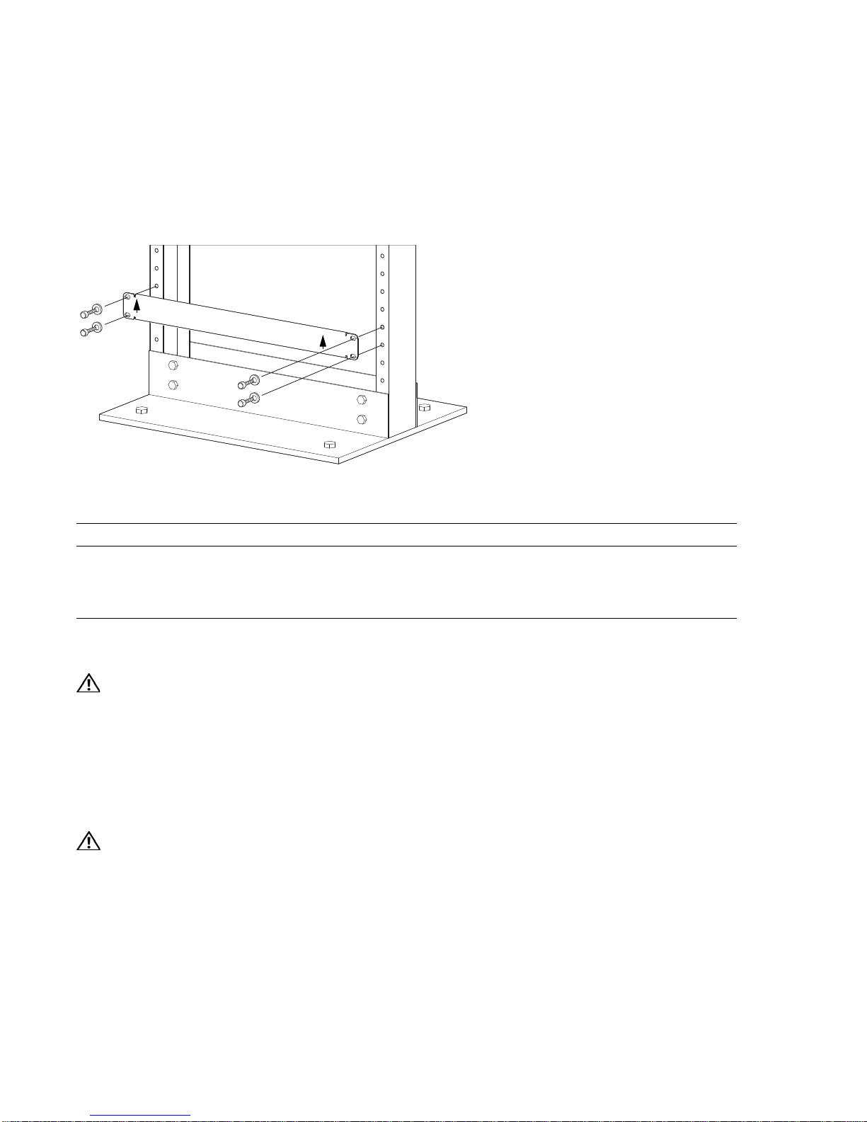
Installing the Equipment Rack Shelf Bar
The rack shelf bar (
Figure 4-1
) enables you to easily position the chassis into the rack and provides the
unit additional stability. The E1200 system must be mounted in a rack that is permanently secured to the
floor.
Figure 4-1. Rack Shelf Bar
UP
www.dell.com | support.dell.com
UP
F
To install a equipment rack shelf bar:
Step Task
1 Determine the chassis mounting location in the equipment rack.
2 Orient the bar with the arrows pointing upward. The smooth side of the bar should face outward.
3 Attach the bar to the equipment rack brackets using the mounting screws provided by the manufacturer.
Standard Front Chassis Mounting
WARNING: To prevent bodily injury when mounting or servicing this unit in a rack, you must take special
precautions to ensure that the system remains stable. The following guidelines are provided to ensure your
safety:
• This unit should be mounted at the bottom of the rack if it is the only unit in the rack.
• When mounting this unit in a partially filled rack, load the rack from the bottom to the top with the heaviest
component at the bottom of the rack.
• If the rack is provided with stabilizing devices, install the stabilizers before mounting or servicing the unit in
the rack.
WARNING: Pour éviter toute blessure corporelle pendant les opérations de montage ou de réparation de
cette unité en casier, il convient de prendre des précautions spéciales afin de maintenir la stabilité du
système. Les directives ci-dessous sont destinées à assurer la protection du personnel:
• Si cette unité constitue la seule unité montée en casier, elle doit être placée dans le bas.
• Si cette unité est montée dans un casier partiellement rempli, charger le casier de bas en haut en plaçant
l'élément le plus lourd dans le bas.
• Si le casier est équipé de dispositifs stabilisateurs, installer les stabilisateurs avant de monter ou de
réparer l'unité en casier.
20 | Installing the AC Chassis

WARNING: Zur Vermeidung von Körperverletzung beim Anbringen oder Warten dieser Einheit in einem
Gestell müssen Sie besondere Vorkehrungen treffen, um sicherzustellen, daß das System stabil bleibt. Die
folgenden Richtlinien sollen zur Gewährleistung Ihrer Sicherheit dienen:
• Wenn diese Einheit die einzige im Gestell ist, sollte sie unten im Gestell angebracht werden.
• Bei Anbringung dieser Einheit in einem zum Teil gefüllten Gestell ist das Gestell von unten nach oben zu
laden, wobei das schwerste Bauteil unten im Gestell anzubringen ist.
• Wird das Gestell mit Stabilisierungszubehör geliefert, sind zuerst die Stabilisatoren zu installieren, bevor
Sie die Einheit im Gestell anbringen oder sie warten.
NOTE: Dell Force10 recommends that you install and operate the E1200 system in a standard 19-inch or 23-
inch equipment rack.
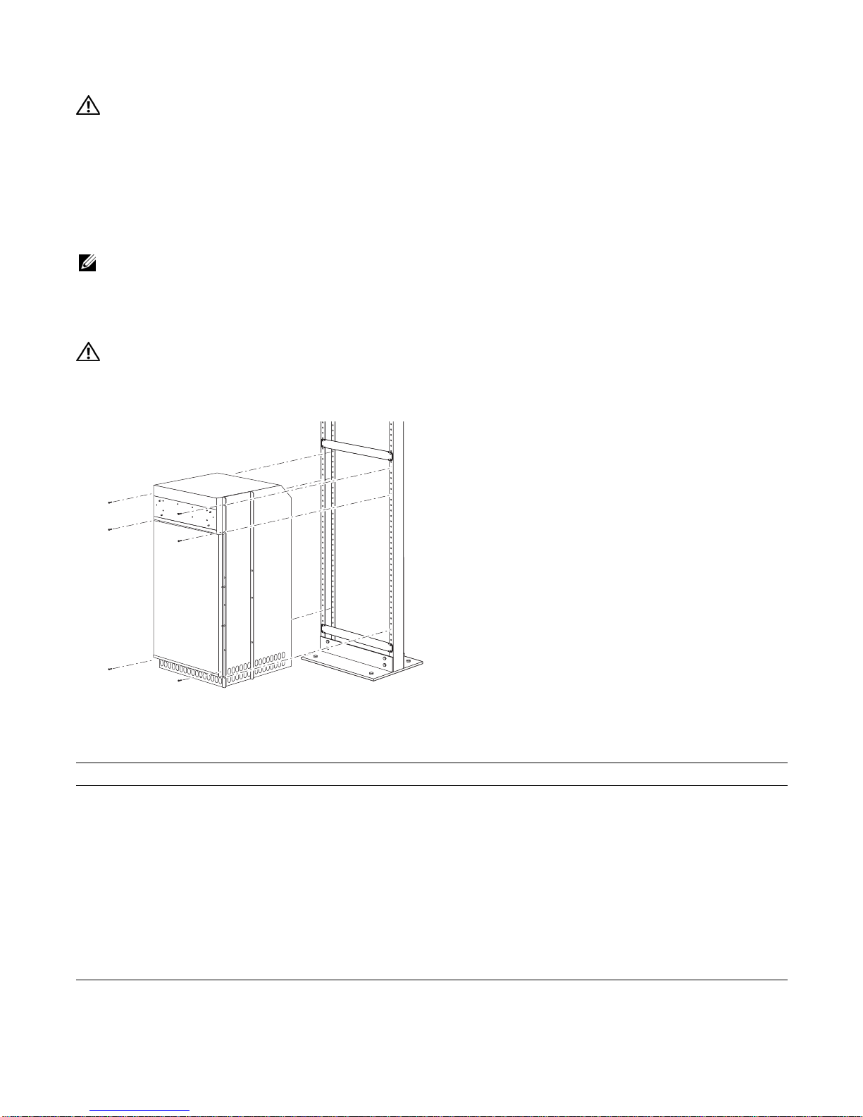
Install the E1200 system after you secure the equipment rack shelf bar. Load the chassis in the lower half
of an empty rack to avoid a top-heavy rack (
WARNING: Do not remove the Front shipping Cover during the initial installation process. The cover provides
Figure 4-2
front handles to assist in lifting and prevents damage to the internal framework and EMI seals.
Figure 4-2. Rack Mounting the Chassis
).
FN00046B
To install the chassis into a prepared rack:
Step Task
1 If you are center or rear-mounting the chassis in a 19-inch rack, adjust the chassis rack mounting brackets to the
desired position.
2 If you are mounting the chassis in a 23-inch rack, install the 23-inch adapter brackets.
3 Using a hand cart, pallet jack, or forklift, align the rack-mount holes with the equipment rack holes, situating the
chassis on top of the equipment rack shelf bar.
4 Insert rack mounting screws in the holes that are not obscured by the metal chassis shipping cover. Tighten the
screws. See
5 Loosen and remove the screws that secure the chassis Front Shipping Cover and remove the cover.
6 Insert the remaining rack mounting screws and tighten to secure the chassis in the rack.
Figure 4-2
.
Installing the AC Chassis | 21

Installing the Chassis into an Equipment Cabinet
Install the E1200 system after you secure the rack shelf bar. Load the chassis in the lower half of the
cabinet to avoid it becoming top-heavy. Make sure the cabinet is positioned with adequate space in the
front, rear, and sides of the unit for proper ventilation, access to cables, and access for maintenance.
Refer to
Chapter 3, Site Preparation
for complete requirements.
To install the chassis into an equipment cabinet:
Step Task
1 Install the equipment rack shelf bar.
2 Adjust the chassis mounting brackets to the desired front-rear position and add a 23-inch adapter brackets as
www.dell.com | support.dell.com
3 Using a hand cart, pallet jack, or forklift, align the rack-mount holes with the cabinet holes.
4 Insert rack mounting screws in the holes that are not obscured by the metal chassis shipping cover. Tighten the
5 Loosen and remove the screws attaching the chassis shipping cover. Remove the shipping cover.
6 Insert the remaining mounting screws and tighten to secure the chassis in the cabinet.
required.
screws.
22 | Installing the AC Chassis
5
Installing the DC Chassis
This chapter provides instructions to rack mount your E1200 system into a standard 19-inch or 23-inch
equipment rack. It contains the following sections:
• Unpacking the E1200 System
• Standard Front Chassis Mounting
• Installing the Chassis into an Equipment Cabinet
Unpacking the E1200 System
The E1200 DC system and components are shipped on a wooden pallet with Front Shipping cover.
Remove the chassis from the shipping packaging and move the chassis with a hand cart, pallet jack, or
fork lift to its rack. Do not unpack the power supplies, fan trays, air filter, or cards until the chassis is
installed.
WARNING: The E1200 DC shipping containers each weigh up to 400 pounds. The unpacked chassis and
pallet weigh approximately 200 pounds. Do not attempt to lift or move the chassis without the use of a hand
cart, pallet jack, or forklift.
CAUTION: Lift the E1200 chassis only with the handles provided or from the bottom. Lifting by the chassis
shelves will cause chassis damage. Do not remove the shipping cover during the installation process. The
cover prevents damage to the internal framework and EMI seals.
WARNING: Electrostatic discharge (ESD) damage can occur when components are mishandled. Always
wear an ESD-preventative wrist or foot-heal ground strap when handling RPMs, SFM3s, or line cards. After
you remove the original packaging, place RPMs, SFM3s, and line cards directly into the chassis or on an
antistatic surface.
WARNING: Complete the chassis installation into the rack before you install any other component (fan trays,
power supplies, line cards, RPMs, SFM3s, cables).
WARNING: This product relies on the building's installation for short-circuit (overcurrent) protection. Ensure
that a fuse or circuit breaker no less than 150A is used on the phase conductors (all current-carrying
conductors).
WARNING: Pour ce qui est de la protection contre les courts-circuits (surtension), ce produit dépend de
l'installation électrique du local. Vérifier qu'un fusible ou qu'un disjoncteur de 150A? est utilisé sur les
conducteurs de phase (conducteurs de charge).
WARNING: Dieses Produkt ist darauf angewiesen, daß im Gebäude ein Kurzschluß- bzw. Überstromschutz
installiert ist. Stellen Sie sicher, daß eine Sicherung oder ein Unterbrecher von nicht mehr 150A? an den
Phasenleitern (allen stromführenden Leitern) verwendet wird.
WARNING: Class 1 laser product.
WARNING: Produit laser de classe 1.
WARNING: Laserprodukt der Klasse 1.
Installing the DC Chassis | 23
Installing the Equipment Rack Shelf Bar
The rack shelf bar (
Figure 5-1
) enables you to easily position the chassis into the rack and provides the
unit additional stability. The E1200 system must be mounted in a rack that is permanently secured to the
floor.
Figure 5-1. Rack Shelf Bar
UP
www.dell.com | support.dell.com
UP
F
To install a equipment rack shelf bar:
Step Task
1 Determine the chassis mounting location in the equipment rack.
2 Orient the bar with the arrows pointing upward. The smooth side of the bar should face outward.
3 Attach the bar to the equipment rack brackets using the mounting screws provided by the manufacturer.
Standard Front Chassis Mounting
WARNING: To prevent bodily injury when mounting or servicing this unit in a rack, you must take special
precautions to ensure that the system remains stable. The following guidelines are provided to ensure your
safety:
• This unit should be mounted at the bottom of the rack if it is the only unit in the rack.
• When mounting this unit in a partially filled rack, load the rack from the bottom to the top with the heaviest
component at the bottom of the rack.
• If the rack is provided with stabilizing devices, install the stabilizers before mounting or servicing the unit in
the rack.
WARNING: Pour éviter toute blessure corporelle pendant les opérations de montage ou de réparation de
cette unité en casier, il convient de prendre des précautions spéciales afin de maintenir la stabilité du
système. Les directives ci-dessous sont destinées à assurer la protection du personnel:
• Si cette unité constitue la seule unité montée en casier, elle doit être placée dans le bas.
• Si cette unité est montée dans un casier partiellement rempli, charger le casier de bas en haut en plaçant
l'élément le plus lourd dans le bas.
• Si le casier est équipé de dispositifs stabilisateurs, installer les stabilisateurs avant de monter ou de
réparer l'unité en casier.
24 | Installing the DC Chassis
WARNING: Zur Vermeidung von Körperverletzung beim Anbringen oder Warten dieser Einheit in einem
Gestell müssen Sie besondere Vorkehrungen treffen, um sicherzustellen, daß das System stabil bleibt. Die
folgenden Richtlinien sollen zur Gewährleistung Ihrer Sicherheit dienen:
• Wenn diese Einheit die einzige im Gestell ist, sollte sie unten im Gestell angebracht werden.
• Bei Anbringung dieser Einheit in einem zum Teil gefüllten Gestell ist das Gestell von unten nach oben zu
laden, wobei das schwerste Bauteil unten im Gestell anzubringen ist.
• Wird das Gestell mit Stabilisierungszubehör geliefert, sind zuerst die Stabilisatoren zu installieren, bevor
Sie die Einheit im Gestell anbringen oder sie warten.
NOTE: Dell Force10 recommends that you install and operate the E1200 system in a standard 19-inch or 23-
inch equipment rack.
Install the E1200 system after you secure the equipment rack shelf bar. Load the chassis in the lower half
of an empty rack to avoid a top-heavy rack (
WARNING: Do not remove the Front shipping Cover during the initial installation process. The cover provides
Figure 5-2
front handles to assist in lifting and prevents damage to the internal framework and EMI seals.
Figure 5-2. Rack-Mounting the Chassis
)
FN00046B
To install the chassis into a prepared rack:
Step Task
1 If you center- or rear-mount the chassis in a 19-inch rack, adjust the chassis rack-mounting brackets to the desired
position.
2 If you mount the chassis in a 23-inch rack, install the 23-inch adapter brackets.
3 Use a hand cart, pallet jack, or forklift to align the rack-mount holes with the equipment rack holes, situating the
chassis on top of the equipment rack shelf bar.
4 Insert rack-mounting screws in the holes that are not obscured by the metal chassis shipping cover. Tighten the
screws. See
5 Loosen and remove the screws that secure the chassis Front Shipping Cover and remove the cover.
6 Insert the remaining rack-mounting screws and tighten to secure the chassis in the rack.
Figure 5-2
.
Installing the DC Chassis | 25

Installing the Chassis into an Equipment Cabinet
Install the E1200 system after you secure the rack shelf bar. Load the chassis in the lower half of the
cabinet to avoid it becoming top-heavy. Make sure the cabinet is positioned with adequate space in the
front, rear, and sides of the unit for proper ventilation, access to cables, and access for maintenance.
Refer to
Chapter 3, Site Preparation
for complete requirements.
To install the chassis into an equipment cabinet:
Step Task
1 Install the equipment rack shelf bar.
2 Adjust the chassis mounting brackets to the desired front-rear position and add a 23-inch adapter brackets as
www.dell.com | support.dell.com
3 Using a hand cart, pallet jack, or forklift, align the rack-mount holes with the cabinet holes.
4 Insert rack-mounting screws in the holes that are not obscured by the metal chassis shipping cover. Tighten the
5 Loosen and remove the screws attaching the chassis shipping cover. Remove the shipping cover.
6 Insert the remaining mounting screws and tighten to secure the chassis in the cabinet.
required.
screws.
26 | Installing the DC Chassis
Installing Fan Trays
6
Access the fan tray slots from the rear of the chassis (
chassis. When a fan tray is not installed in the lower slot, a self-closing door will seal the slot. Panel
blanks are not required. However, to ensure fail-safe chassis operation, do not operate the chassis with
only one fan tray for more than 30 minutes.
WARNING: Install the fan trays before you supply power to the system.
WARNING: Electrostatic discharge (ESD) damage can occur when components are mishandled. Always
wear an ESD-preventative wrist or foot-heal ground strap when handling chassis components. After you
remove the original packaging, place chassis components on an antistatic surface.
Figure 6-1. .Installing Fan Tray
Figure 6-1
). Two fan trays are required in the
Installing Fan Trays | 27
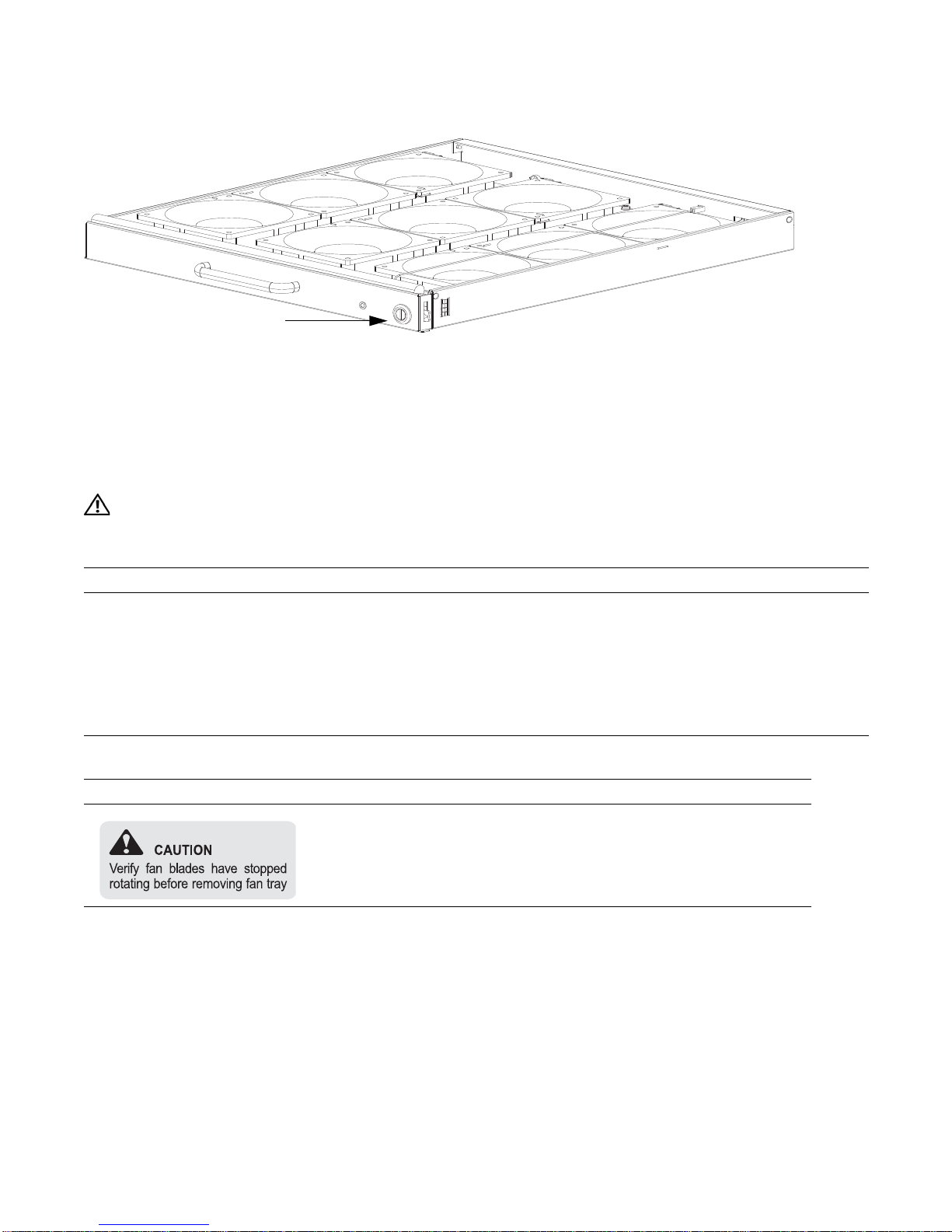
Figure 6-2. Fan Tray
screw latch
Install the fan trays after the chassis is installed securely in the equipment rack. Access the fan tray slots
www.dell.com | support.dell.com
from the rear side of the chassis. To ensure proper temperature and airflow control, all six fan trays must
be installed before you supply power to the system. You will need a #2 Phillips screwdriver to tighten the
screws that secure the fan trays to the chassis. A fan tray can be installed in any fan tray slot.
To install fan trays:
WARNING:
Table 6-1
is an illustration of the fan tray safety labels: Prevent exposure and contact with
hazardous voltages. Do not attempt to operate this system without the safety cover provided with each PEM.
Step Task
1 Unpack the fan tray.
2 Prior to inserting a fan tray, fully turn its screw latch counter-clockwise (with flathead screwdriver) until the fan
tray latching mechanism fully retracts into the fan tray (see
3 Grip the fan tray handle. Slide the connector end of each fan tray into the slot until it stops and the handle end is
Figure 6-2
).
flush with the chassis rear.
4 Secure the fan trays into place by turning the screw latch clockwise.
Table 6-1. Fan Tray Safety Labels
Label Location
Fan tray faceplate
28 | Installing Fan Trays
7
A
Installing AC Power Supplies
The E1200 system requires a minimum of 3 AC power supplies in a shelf (0, 1, 2 or 3, 4, 5) to operate.
For full redundancy use 6 power supplies so that if one power supply fails in one shelf, the system
remains operational operates with the 3 power supplies in the other shelf. To comply with safety agency
and EMI regulations, you must install the AC-cord retainer over all power cords. The E1200 chassis
contains 6 AC power supply slots, as shown in
NOTE: If you are installing only three power supplies, they must be installed in the same row. FTOS will
generate an error message if the three power supplies are not in the same row.
NOTE: The On/Standby switch disconnects power to the rest of the chassis from all 6 AC power supplies
slots. When the AC cord is attached, power supply fans will spin and the LEDs will indicate status while the
On/Standby switch is in Standby.
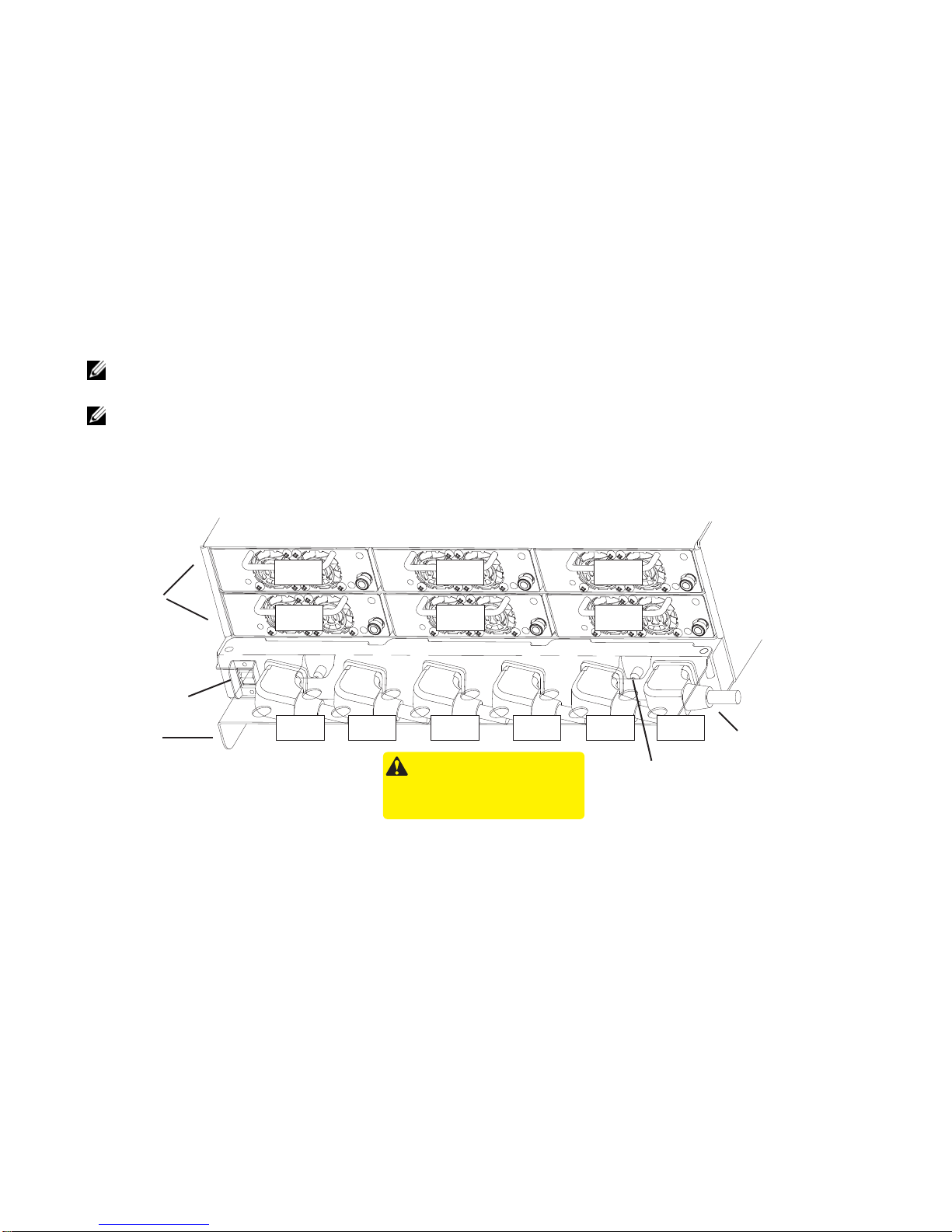
Figure 7-1. E1200i AC Power Supply Shelf
Figure 7-1
.
Power
Supplies
On/Standby
Switch
C-Cord Retainer
Safety Cover
AC- 0
AC- 3
AC- 0 AC-3 AC-1 AC-4 AC-2 AC- 5
WARNING -
HIGH LEAKAGE CURRENT. EARTH CONNECTION
ESSENTIAL BEFORE CONNECTING SUPPLY.
COURANT DE FUITE ELEVE. RAC CORDEMENT
A LA TERRE INDISPENSABLE AVANT LE
RACCOR DEMENT AU RESEAU.
This retainer must be in place during normal operation.
Do not remove except for servicing
AC- 1
AC- 4
/
/
/
AC- 2
AC- 5
Locking Screw
AC Power Plugs
Installing AC Power Supplies | 29
 Loading...