

Page 1

L
e
l
X
t
a
t
E
e
y
a
p
g
m
DE
Fil
A Del
L D
Ga
Technic
Obj
ewa
l White P
ct S
De
per
tora
loy
e
ent Guide
Dell │ S
Storage
orage
ngineering
Page 2

Dell DX Object Storage – File Gateway Deployment Guide
THIS DOCUMENT IS FOR INFORMATIONAL PURPOSES ONLY, AND MAY CONTAIN TYPOGRAPHICAL ERRORS
AND TECHNICAL INACCURACIES. THE CONTENT IS PROVIDED AS IS, WITHOUT EXPRESS OR IMPLIED
WARRANTIES OF ANY KIND.
© 2010 Dell Inc. All rights reserved. Reproduction of this material in any manner whatsoever without
the express written permission of Dell Inc. is strictly forbidden. For more information, contact Dell.
Dell, the DELL logo, and the DELL badge, PowerEdge, and PowerVault are trademarks of Dell Inc.
Microsoft, Windows, Windows Server, and Active Directory are either trademarks or registered
trademarks of Microsoft Corporation in the United States and/or other countries. Other tra demarks and
trade names may be used in this document to refer to either the entities claiming the marks and names
or their products. Dell Inc. disclaims any proprietary interest in trademarks and trade names other than
its own.
December 2010
Page ii
Page 3

Dell DX Object Storage – File Gateway Deployment Guide
Contents
Scope of this Document and Requirements ......................................................................... 4
Conventions Used in This Document ................................................................................. 4
Working with Files and Commands ................................................................................... 4
Deployment Checklist .................................................................................................. 5
Single-Server, Standalone Authentication, Local Spooler ...................................................... 5
Single-Server, Active Directory Member, Local Spooler ........................................................ 5
Failover, Standalone Authentication, External Spooler ........................................................ 6
Failover, Active Directory Member, External Spooler .......................................................... 6
Site Survey ............................................................................................................... 6
Architecture ............................................................................................................. 7
Standard hardware ................................................................................................... 7
Specific CFS Configurations ......................................................................................... 7
Single-server Configuration ...................................................................................... 7
Hardware ......................................................................................................... 7
Network .......................................................................................................... 8
Failover Configuration ............................................................................................ 8
Hardware ......................................................................................................... 8
Network .......................................................................................................... 9
Gateway Protocols ................................................................................................ 10
Other hardware ...................................................................................................... 10
Software .............................................................................................................. 10
How it all works together .......................................................................................... 11
Standard DX Object Storage Cluster ........................................................................... 11
DX Object Storage File Gateway (single-server) ............................................................. 12
DX Object Storage File Gateway (Failover) ................................................................... 13
Set up the DX Object Storage Cluster ............................................................................... 14
Assumptions and Requirements ................................................................................... 14
Configure the Cluster ............................................................................................... 14
Set up the CFS Server ................................................................................................. 16
Assumptions and Requirements ................................................................................... 16
Validate BIOS settings .............................................................................................. 16
Create RAID1 Volumes .............................................................................................. 17
Page 1
Page 4

Dell DX Object Storage – File Gateway Deployment Guide
Install and Configure Red Hat Enterprise Linux ................................................................ 17
Create the Master Boot Record (MBR) on the Second Drive ............................................... 23
Disable SELinux ...................................................................................................... 24
Create the YUM Repository and Install Packages ............................................................... 25
Stop and Disable Services .......................................................................................... 28
Set up the NTP Server .............................................................................................. 28
Configure the Network Interfaces for Bonding ................................................................. 29
Configure the Domain Name Service Resolver .................................................................. 31
Install the CFS Software ............................................................................................ 32
Create the Spooler and Cache File Systems ....................................................................... 33
Create disk partitions and spooler file systems (Single-server solution) ................................... 34
External Spooler File System (Failover solution) ............................................................... 35
Configure the MD3200i ........................................................................................... 35
Configure the Cluster Name Space (CNS) .......................................................................... 41
C o n f i g u r e t h e C F S a n d i t s DX O b j e c t S t o r a g e M o u n t P o i n t s ................................................................. 44
Configure Gateway Protocols ........................................................................................ 46
SMB/CIFS Gateway Service ......................................................................................... 46
Stand-alone Server (Workgroup Authentication) ............................................................ 47
Active Directory Domain Member Server ..................................................................... 51
Edit the krb5 File .............................................................................................. 51
Configure the SMB/CIFS Server .............................................................................. 52
NFS Gateway Service ............................................................................................... 56
Before Configuring NFS .......................................................................................... 56
Disable IP forwarding .......................................................................................... 56
Configure NFS to share the CFS mount ........................................................................ 56
Configure Share Resources ........................................................................................... 56
SMB/CIFS Shared Resource Configuration ....................................................................... 57
Add a Share (Standalone Server) ............................................................................... 57
Add a share (Active Directory Domain Member) ............................................................. 59
Remove a Share ................................................................................................... 60
NFS Shared Resource Configuration .............................................................................. 60
Add an NFSv3 Share Point ....................................................................................... 61
Remove an NFS Share Point ..................................................................................... 61
Administrative Maintenance Procedures ........................................................................... 61
Starting CFS and CNS ............................................................................................... 61
Page 2
Page 5

Dell DX Object Storage – File Gateway Deployment Guide
Shut Down CFS and CNS ............................................................................................ 62
Special Considerations for MD3200i Spooler .................................................................. 63
File Revisions and Dell DX Object Storage File Deletion ...................................................... 63
Dell DX Object Storage Metadata and Policies ............................................................... 63
Custom Metadata ................................................................................................. 64
CFS / DX Object Storage Lifecycle Policies ..................................................................... 65
CFS-Grab ........................................................................................................... 66
CFS-Loglevel ....................................................................................................... 67
Troubleshooting ..................................................................................................... 67
Appendix A. Temp and Logging Space Configuration ............................................................. 67
Appendix B. Gateway Protocol Support ............................................................................ 68
Protocol Gateway Limitations ..................................................................................... 68
Supported Protocols .............................................................................................. 68
Access Control Lists .............................................................................................. 68
SMB/CIFS Protocol Support ........................................................................................ 68
Appendix C. NFS Client Guidelines .................................................................................. 69
APPENDIX D. CFS Failover ............................................................................................. 70
Configure the Failover CFS Server ................................................................................ 70
Failover to Secondary CFS ......................................................................................... 70
Page 3
Page 6

Dell DX Object Storage – File Gateway Deployment Guide
Scope of this Document and Requirements
This document provides instruction for deploying either a CIFS or NFS gateway solution on the Dell DX
Object Storage platform. Successful deployment enables customers to use a common file system with
which they are comfortable.
The following is required before beginning the deployment:
All DX Object Storage hardware has been racked and cabled.
The Caringo CAStor software has been installed on the Cluster Services Node of the DX Object
Storage system.
The components of the solution are properly networked.
You have all required network information (see Site Survey included in this document).
Conventions Used in This Document
The following fonts and conventions are used in this document to identify required actions and example
text as it appears in the command line interface (CLI).
CLI text that you enter as part of a command or editing a file. (input)
Variable in code
Resulting text as it appears in a command-line interface. (output)
Emphasis in resulting text after a command is entered.
File name, directory name, or variable name
Working with Files and Commands
This document assumes that the reader has a working knowledge of Linux. Running the commands or
navigating the file system can be executed either through a command line interface or navigated
through the X-Windows GUI.
In instances where command line interface is the only option, the document will provide specific
instruction on what you need to type.
Page 4
Page 7

Dell DX Object Storage – File Gateway Deployment Guide
Deployment Checklist
Complete the steps below for the type of CFS solution you are deploying.
Single-Server, Standalone Authentication, Local Spooler
(DX Cluster + 1 CFS, not a member of Active Directory)
Complete the Site Survey
Technical review.
Order placement and delivery.
Rack and cable (power and network) the DX Object Cluster and the CFS Server(s).
Set up the DX Object Cluster.
Set up the CFS Server.
Create disk partitions and spooler file systems.
Configure Cluster Name Space.
Configure the CFS and its DX Object Storage Mount Points.
Configure SMB/CIFS gateway protocols for standalone server, or configure NFS gateway service.
Add a SMB/CIFS or NFS share for standalone server.
Single-Server, Active Directory Member, Local Spooler
(DX Cluster + 1 CFS, member of Active Directory)
Complete the Site Survey
Technical review.
Order placement and delivery.
Rack and cable (power and network) the DX Object Cluster and the CFS Server(s).
Set up the DX Object Cluster.
Set up the CFS Server.
Create disk partitions and spooler file systems.
Configure Cluster Name Space.
Configure the CFS and its DX Object Storage Mount Points.
Configure SMB/CIFS gateway protocols for Active Directory Member Server.
Add a share (Active Directory Domain Member).
Page 5
Page 8

Dell DX Object Storage – File Gateway Deployment Guide
Failover, Standalone Authentication, External Spooler
(DX Cluster + 2 CFS Systems + MD3200i, not a member of Active Directory)
Complete the Site Survey
Technical review.
Order placement and delivery.
Rack and cable (power and network) the DX Object Cluster and the CFS Server(s).
Set up the DX Object Cluster.
Set up the CFS Server.
Configure the External Spooler.
Configure Cluster Name Space.
Configure the CFS and its DX Object Storage Mount Points.
Configure SMB/CIFS gateway protocols for standalone server, or configure NFS gateway service.
Add a SMB/CIFS or NFS share for standalone server.
Configure the Failover CFS Server.
Failover, Active Directory Member, External Spooler
(DX Cluster + 2 CFS Systems + MD3200i, member of Active Directory)
Complete the Site Survey
Technical review.
Order placement and delivery.
Rack and cable (power and network) the DX Object Cluster and the CFS Server(s).
Set up the DX Object Cluster.
Set up the CFS Server.
Configure the External Spooler.
Configure Cluster Name Space.
Configure the CFS and its DX Object Storage Mount Points.
Configure SMB/CIFS gateway protocols for Active Directory Member Server.
Add a share (Active Directory Domain Member).
Configure the Failover CFS Server.
Site Survey
Use the site survey to gather information about the customer site. You will use some of this
information to determine which CFS solution is best for your customer, and much of the information
will be vital to a successful deployment.
DX CFS Site
Survey.docx
Page 6
Page 9

Dell DX Object Storage – File Gateway Deployment Guide
Architecture
The DX Object Storage Gateway Solution is offered in two different types of configurat ions — singleserver and failover.
Standard hardware
The following briefly describes the standard hardware components of DX Object Storage G ateway
solutions. In most cases, none of these components are yet installed at the customer site.
CFS Server – This server hosts the content file server software that presents the Dell DX Object
Storage system as a standard file system. In single-server solutions, this server also provides a
spool cache on local disk.
Cluster Services Node (CSN) – This node is the head of the DX Object Storage systems and
hosts the services that run on the cluster, such as cluster services, storage services, and
content router (if applicable). It is not used for data storage.
Storage Nodes – These nodes host data that is indirectly written to them by application servers
(via the spool cache). A minimum of two nodes is required, and e ach data object has at least
one replica.
Shared Storage System – Shared storage is a cache where files are stored before they get
written to the DX Object Storage and also where they can be accessed on subsequent reads, if
locally available. A separate shared storage system, such as the MD3200i is required for failover
solutions. In these types of solutions, if the gateway server fails over to another gateway
server, the common spool cache is still available to either write its data to the storage nodes,
or serve data to clients.
Specific CFS Configurations
CFS configurations front-end a DX Object Storage cluster that has one CSN an d at least two storage
nodes. There are two types of CFS configurations offered – single server (no failover) and high
availability (failover). A failover solution is recommended in environments that require high
performance and/or have large file system configurations.
Single-server Configuration
The minimal CFS configuration is a single CFS server the uses internal storage for storing the spooled
data and namespace. This configuration is recommended when CFS failover is not required and when
the spooled data and namespace capacity requirements are less than 1TB.
Hardware
(1) PowerEdge R410 server
o Chassis: Up to four Hot-Plug Hard Drives, LCD diagnostics
Processor(s): 2 x E5620, 2.4GHz 12M Cache, Turbo, HT, 1066MHz Max M e m
o
o
Memory Configuration: 24GB Memory (6x4GB), 1066MHz Dual Ranked RDIMMs for
Processors, Optimized
o HDD Configuration: RAID1/RAID1 hard drive configuration
o Hard Drives:
(2) 500GB 7.2K RPM Near-Line SAS 3.5in HDD for OS and application
(2) 1TB 7.2K RPM Near-Line SAS 3.5in HDD for spooled data and namespace
o Primary Controller: SAS 6.iR SAS internal RAID adapter for Hot Plug Configuration, PCI-
Express
Page 7
Page 10
Dell DX Object Storage – File Gateway Deployment Guide
o PSU: 500Watt Redundant power supplies
o Embedded Management: iDRAC6 Enterprise
o Network Adapter: Broadcom NetXtreme II 5709 Gigabit NIC w/TO E & iSOE, Quad Port,
Copper, PCIe-4
o DVD-ROM Drive
o Operating System: RHEL 6 X64 Basic with 3 Year Subscription
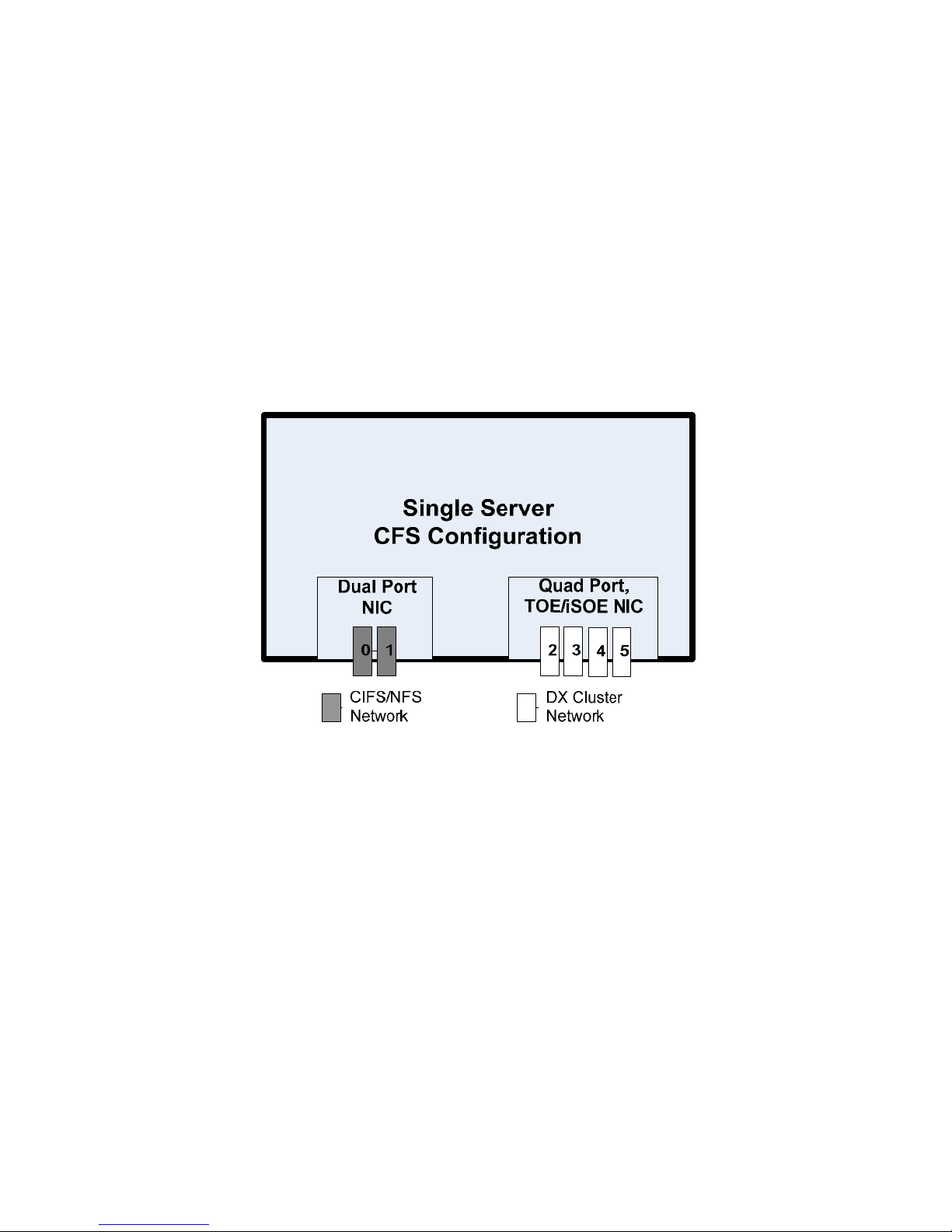
Network
The CFS server is configured with one Broadcom dual port BCM 5716 controller and one Broadcom quad
port NetExtreme II 5709 GbE controller for a total of six GbE ports. The recommended network port
allocation for a single CFS configuration is:
Connect NIC ports 0 and 1 to the CIFS/NFS network.
Connect NIC ports 3 thru 5 to the DX Storage Cluster network.
Failover Configuration
The failover configuration allows CFS servers to be deployed in pairs so that if one server fails, the
share can be recovered by the other CFS server to minimize recovery time. In this configuration, the
CFS servers utilize iSCSI storage to store spooled data.
Hardware
This configuration consists of the following hardware:
(2) PowerEdge R410 servers
o Chassis: Up to four Hot-Plug Hard Drives, LCD diagnostics
o Processor(s): 2 x E5620, 2.4GHz 12M Cache, Turbo, HT, 1066MHz Max Mem
o Memory Configuration: 24GB Memory (6x4GB), 1066MHz Dual Ranked RDIMMs for
Processors, Optimized
o HDD Configuration: RAID 1 configuration; internal drives in RAID 1 for OS and
application; spooled data and namespace stored on iSCSI
o Primary Controller: SAS 6.iR SAS internal RAID adapter for Hot Plug Configuration, PCI-
Express
o Hard Drives: (2) 500GB 7.2K RPM Near-Line SAS 3.5in HDD
o PSU: 500Watt Redundant power supplies
o Embedded Management: iDRAC6 Enterprise
Page 8
Page 11
Dell DX Object Storage – File Gateway Deployment Guide
o Network Adapter: Broadcom NetXtreme II 5709 Gigabit NIC w/TO E & iSOE, Quad Port,
Copper, PCIe-4
o DVD-ROM Drive
o Operating System: RHEL 6 X64 Basic with 3 Year Subscription
(1) iSCSI Storage: MD3200i
o Controllers: Single or Dual controller options
o Hard Drives: Up to 12 3.5in HDD with the following HDD options
- 500GB near-line SAS 6GB, 7.2K, 3.5in HDD
- 300GB SAS 6GB, 15K, 3.5in HDD
- 450GB SAS 6GB, 15K, 3.5in HDD
- 600GB SAS 6GB, 15K, 3.5in HDD
- 2TB near-line SAS 6GB, 7.2K, 3.5in HDD
o HDD Configuration: RAID5
Network
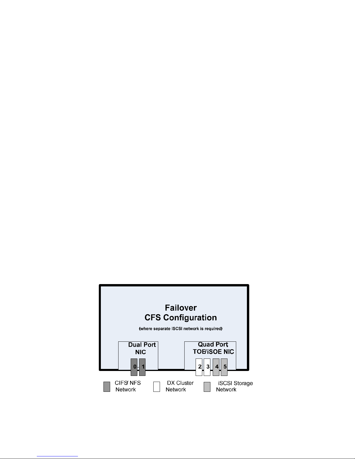
For a failover CFS configuration, the iSCSI storage can be on its own switch isolated from the DX
Storage Cluster or it can be attached to the DX Cluster network. In cases where iSCSI storage is
attached to the DX Cluster network, then ports 2 thru 5 can be shared between the iSCSI storage and
DX Storage Cluster. In this configuration, it is recommended to configure network ports for adaptive
load balancing. Sites that have suitable competence may prefer configuration and management of link
aggregation control protocol in place of adaptive load balancing.
The preferred failover network configuration is identical to that shown for a single-server CFS
configuration (above), except that iSCSI traffic will share the four NIC ports that go to the private DX
Storage network. If a site wishes to use pre-existing iSCSI storage that is available on its own VLAN,
then the recommended network port allocation is:
Connect NIC ports 0 and 1 to the CIFS/NFS network.
Connect NIC ports 2 and 3 to the DX Storage Cluster network.
Connect NIC ports 4 and 5 to the iSCSI Storage network.
Page 9
Page 12

Dell DX Object Storage – File Gateway Deployment Guide
Gateway Protocols
The CFS can be configured for NFS or SMB/CIFS gateways. For SMB/CIFS, users and groups can access
the system through standalone authentication, or if Active Directory Services exists, users and groups
can be authenticated through the existing ADS structure. For NFS, Dell supports version 3 only; it does
not support version 4.
Other hardware
The following briefly describes the hardware components that are required to work as part of DX
Object Storage Gateway solutions. They may already be present in the customer environment, or
ordered as part of the solution.
Network Switch(es) – Configuring the solution requires extensive knowledge of how the
customer uses switches to segment VLANs. Some customers may run each VLAN through a
separate switch, and some may segment a switch for multiple VLANs.
Application Server(s) – These servers write data to the spool cache storage in the Gateway
solution. In a non-gateway DX Object Storage solution, they write directly to the storage nodes.
Domain Controller – This server manages logins, authentication, groups and permissi ons.
Domain controller information is an essential part of setting up a gateway solution.
Software
The following briefly describes the standard software components for DX Object Storage Gateway
solutions.
Red Hat Enterprise Linux – This is the operating system that resides on the Cluster Services
Node and the CFS Server. Different versions may run on the CFS Server and the CSN. See the
interoperability matrix for information about versions.
CFS – This is the software on the CFS Server that presents Dell DX Object Storage to clients as a
common file system.
Cluster Services – These services reside on the CSN and enable you to configure the CSN,
define user access, set parameters for backup and restore, and define SCSP Proxy settings.
Content Storage – These services reside on the CSN and enable you to define properties,
licensing, and user access for the whole cluster.
Content Router – These services provide replication of content between remote clusters and
enumeration of DX Object Storage content for other purposes like search indexing or virus
scanning. Content Router is not required if the cluster is not replicating to a remote cluster.
Page 10
Page 13
Dell DX Object Storage – File Gateway Deployment Guide
How it all works together
The data flow in a DX Object Storage File Gateway depends on the type of configuration. The following
examples show, a standard DX Object Storage cluster (for reference purposes), a DX Object Storage
cluster with a single-server gateway, and a DX Object Storage cluster with a failover gateway.
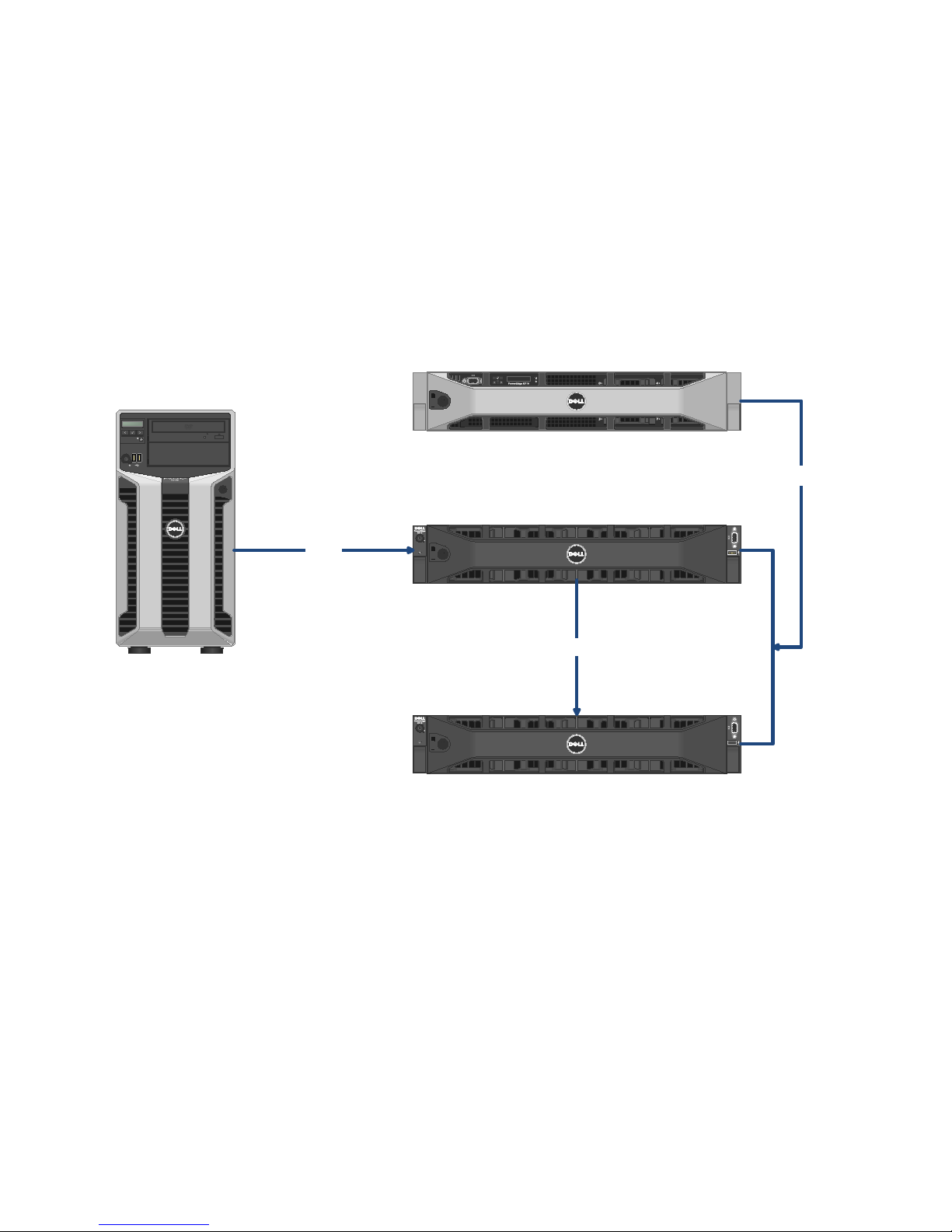
Standard DX Object Storage Cluster
In a basic, standalone DX Object Storage cluster (see Figure 1), an application server writes a data
object directly to a storage node, and the Cluster Services on the CSN refers to its configuration
settings and then tells the object how many times it must replicate.
Figure 1. Standalone DX Object Storage Cluster
Cluster Services Node
Application Server
Cluster Services
Storage Services
Storage Node
Write
Replicate
Storage Node
Page 11
Page 14
Dell DX Object Storage – File Gateway Deployment Guide
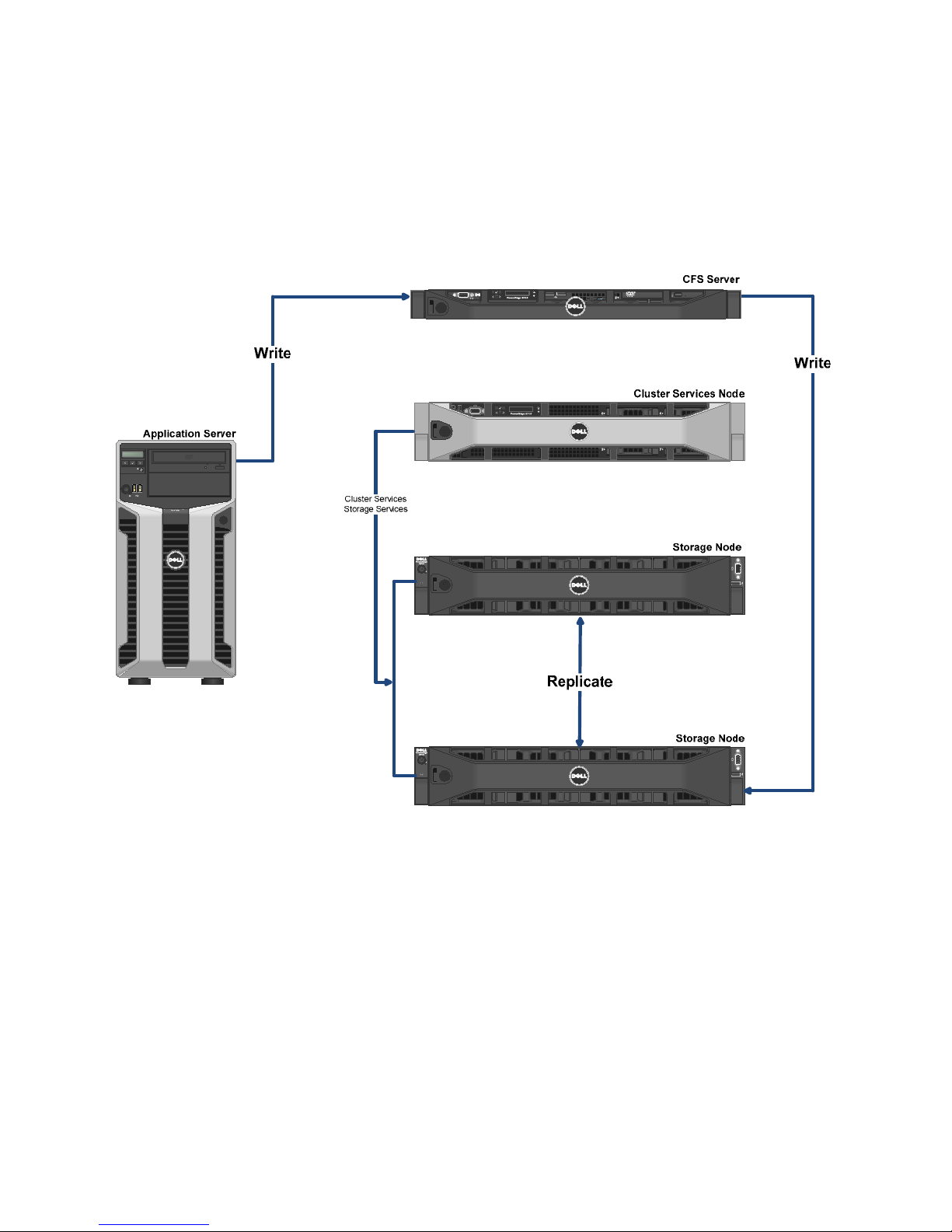
DX Object Storage File Gateway (single-server)
In a DX Object Storage File Gateway, data objects are written to a CFS server before being written to a
Storage Node. In this configuration, the application server and clients are actually viewing objects as
they reside in the spool cache of the CFS server. These objects are presented to the end user as part of
a file system.
Figure 2. DX Object Storage File Gateway (single-server)
Page 12
Page 15
Dell DX Object Storage – File Gateway Deployment Guide
DX Object Storage File Gateway (Failover)
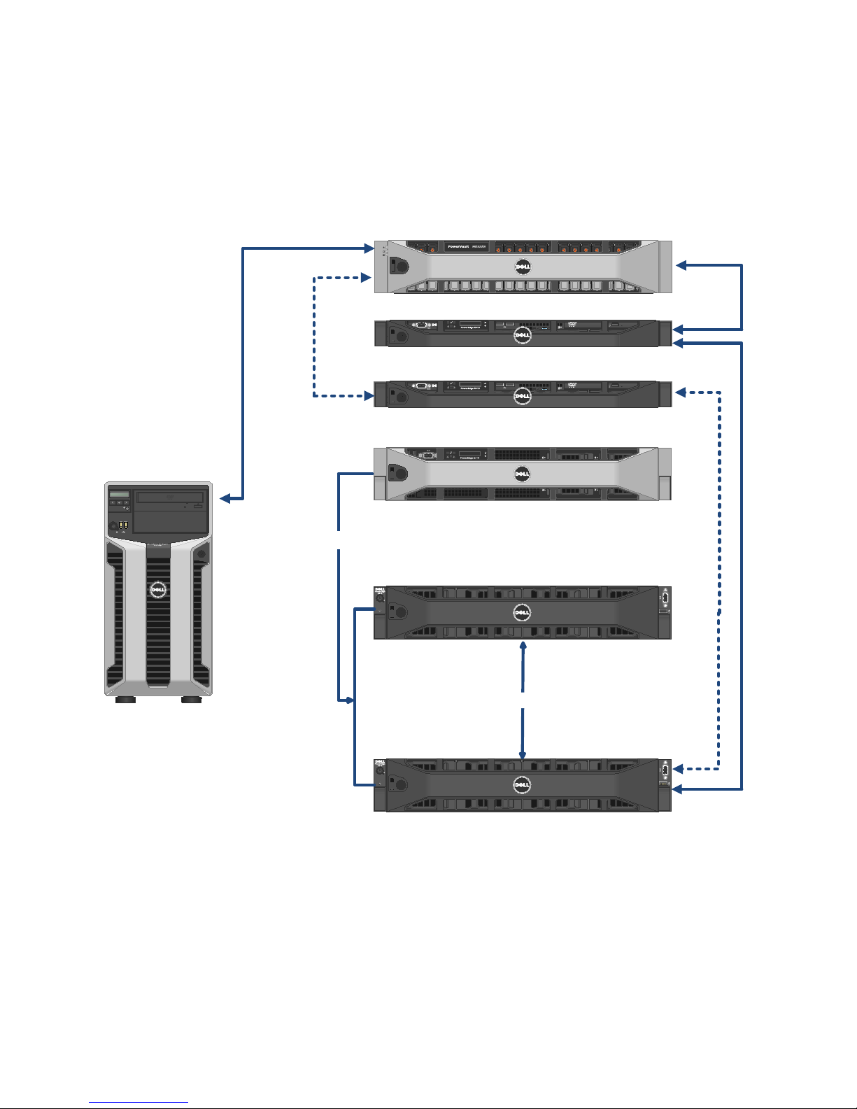
A failover configuration (see Figure 3) provides two CFS server s and a separate dedicated spool/cache.
This configuration provides continuous service on the gateway, as long as the cluster and the shared
storage are running.
Figure 3. DX Object Storage File Gateway (Failover)
Shared Storage (Spool/Cache)
CFS Server (Primary)
CFS Server (Failover)
Cluster Services Node
Application Server
Cluster Services
Storage Services
Storage Node
R
p
e
i
c
l
t
a
e
Storage Node
Page 13
Page 16

Dell DX Object Storage – File Gateway Deployment Guide
Set up the DX Object Storage Cluster
This section includes the steps for setting up and activating the DX Object Storage Cluster.
BEFORE YOU BEGIN: Did you complete the Site Survey?
Assumptions and Requirements
Red Hat Enterprise Linux version 5 or later is factory-installed on the CSN.
You have racked the cluster hardware.
The CSN has been properly cabled to the external network and the storage nodes in the
cluster.
You have a DNS server that the cluster will belong to. (see Site Survey)
You have an IP address that you can assign to the CSN. (see Site Survey)
You have an IP address that you can assign to the cluster. (see Site Survey)
You have a license key for the Caringo software.
Configure the Cluster
1. Ensure that all storage nodes in the cluster are powered off.
2. Power on the CSN and log on.
3. Copy the bundle file to any directory on the CSN.
This file may be available on your installation media, or it can be downloaded from iDrive or
support.dell.com.
4. Open a terminal window and use the cd command to navigate to the directory that contains the
file.
5. Unzip the file.
unzip nameofbundlefile.zip
6. Install the bundle.
# cd bundle
# ./caringo-csn-bundle-install.sh
Installation begins for CSN and its dependent packages.
7. When the installation completes, answer Yes to configure the CSN.
8. Answer Yes when asked if this is the primary CSN.
NOTE: Only a single primary CSN can be configured on the internal network. Having more than
one primary CSN can create conflicts with both DHCP and DX Storage netboot configuration. The
primary CSN must be configured prior to configuration of a secondary CSN. DHCP is not sta rted on
the secondary CSN.
Page 14
Page 17

Dell DX Object Storage – File Gateway Deployment Guide
9. Complete the following network information as prompted. (see the Site Survey)
External IP address for the CSN.
External IP address for the cluster.
Subnet mask.
IP address for the customer’s external gateway.
Internal network interface.
NOTE: This network is a direct line to the cluster and should be separate from public and
gateway networks.
IP addresses for external name servers.
IP addresses for external time servers.
Storage Cluster Name
10. Confirm the values are correct and select Yes.
The CSN immediately reboots and initializes all services. When the CSN comes back up all network
services will be configured and available including SNMP, syslog, DHCP, DNS, NTP, and firewall.
Additionally, the CSN Console will be available, the SCSP Proxy will be configured and started and
the DX Content Router Publisher will be configured and started.
11. On the CSN, open the Mozilla Firefox browser (icon located at top of screen) and go to
http://localhost:8090.
12. Enter the User name and Password.
13. Click the Content Storage tab, and then click the Licensing tab.
14. Click Add License Key.
15. Enter the license key and click Publish.
16. Boot the Storage Nodes, allowing about a minute between booting each node.
17. From the Content Storage tab click View Storage Console.
18. Refresh (F5) occasionally to see the storage nodes come online.
NEXT STEP: Set up the CFS Server
Page 15
Page 18

Dell DX Object Storage – File Gateway Deployment Guide
Set up the CFS Server
BEFORE YOU BEGIN: Did you Set up the DX Object Storage Cluster?
NOTE: Make sure there is a DNS entry for the CIFS/NFS interface of the server. In the case the site
does not have a DNS server, make sure that hostname is resolvable to the CIFS/NFS interface IP
address from the /etc/hosts file. This section includes the steps for setting up and activating the CFS
Server. The procedures should be performed in the following order:
Create RAID volumes on the CFS
Initiate and configure the operating system.
Verify the necessary BIOS Settings
Disable SELinux
Create the YUM Repository
Configure the Network Interfaces for Bonding
Configure the Domain Name Server Resolver
Set up the NTP Server
Install the CFS Software
Stop Gateway Server Services
Assumptions and Requirements
Red Hat Enterprise Linux version 6 or later is factory-installed on the CFS system.
You have configured the CSN, and the cluster is up and running.
IMPORTANT: Before you begin the installation, ensure that you have the following network
information:
Ethernet port addresses
Gateway address
Domain Name Server address
Validate BIOS settings
For the CFS server to function, several options must be set in the BIOS <F2>:
All processors and cores enabled
SATA ports A and B set to Automatic
In the Integrated Devices category, Gb NICs enabled (not with PXE)
Page 16
Page 19

Dell DX Object Storage – File Gateway Deployment Guide
Create RAID1 Volumes
BEFORE YOU BEGIN: Did you Validate BIOS settings
Before installing the operating system, you need to create two RAID1 arrays. One array will used for
the operating system, and the other will be used for a data spool cache.
1. Power on the system.
2. During the boot process, press <Crtl>+<C> when prompted to open the SAS IR configuration tool.
3. Press <Enter> at the SAS6 IR prompt.
4. Select RAID Properties.
5. Select Create R1 Volume.
6. Move the cursor to RAID Disk and toggle to Yes for slot 0 and slot 1.
7. Select C to create the array.
8. Save the changes and exit.
9. Repeat the steps to create the second RAID array.
10. Save and exit the RAID Array tool.
NEXT STEP: Install and Configure Red Hat Enterprise Linux
Install and Configure Red Hat Enterprise Linux
BEFORE YOU BEGIN: Did you Create RAID1 Volumes?
The CFS server comes with Red Hat Linux factory-installed. Before powering on the system, ensure that
you have an external connection.
1. Insert the Red Hat Enterprise Linux version 6 media.
2. Power on the system and press <F11> to enter boot menu, and select Optical Drive.
3. When the first Red Hat screen appears, click Next.
4. Select the installation language and click Next.
5. Select the appropriate keyboard and click Next.
6. Select Basic Storage Devices as the type that will be part of your installation and click Next.
7. When a warning screen appears stating that the device may need to be initialized, click Re-
initialize all.
Page 17
Page 20

Dell DX O
E
o
e
f
)
a
e
o
t
w
f
m
d
o
d
a
e
d
e
o
t
A
m
o
c
a
(
e
l
v
c
a
U
8. Enter
serve
bject Storag
a fully-quali
r.domain.tld
– File Gate
ied Hostna
.
ay Deploym
e for the CF
nt Guide
S that will id
entify it on t
he network (
for example,
NOT
9. Click
10. On th
11. Enter
set t
12. Click
13. Enter
: This hostn
Configure N
e Wired tab
a Connecti
automatic.
the IPv4 Set
the Address
me also nee
twork.
of the Netw
n name and
ings tab, an
, Netmask,
s to be add
rk Connecti
ensure that
then click
nd Gateway
d to the Do
ns screen,
he Connect
dd.
for the CFS
ain Name S
lick Add.
automatical
see Site Sur
rver itself.
y box is che
ey).
ked and MT
is
P
ge 18
Page 21

Dell DX O
d
e
.
e
e
o
c
n
N
w
t
e
k
y
s
e
d
n
i
e
d
t
C
e
d
N
s
d
e
a
i
c
N
14. Provi
bject Storag
e informati
– File Gate
n about the
ay Deploym
DNS servers
nt Guide
and Search
omains wh
re the CFS s
rver will res
de.
15. Click
16. In th
Next
17. On th
18. On th
Spac
Apply, click
time zone s
e password s
e installatio
, and click
Close to exit
reen, selec
creen, enter
type screen
ext.
the Networ
the city in
the Root Pa
, check Revi
Connectio
our time zon
sword, ente
w and mod
s screen, an
e, check Sys
r it again in
fy partitioni
then click
em clock u
onfirm, an
ng layout, s
ext.
es UTC and
then click
lect Use All
lick
ext.
P
ge 19
Page 22

Dell DX O
e
c
e
e
i
c
w
i
s
w
s
h
e
h
w
e
l
v
i
a
e
a
.
e
bject Storag
– File Gate
ay Deploym
nt Guide
19. In th
Devi
storage dev
es list, and
ces screen,
lick the arro
elect only t
to move it
e boot driv
to the Insta
(smallest dr
l Target De
ive) in the D
ices list. Th
ta Storage
n click Next
again
Please Sele
when asked
20. In th
ct a Device
to confirm t
creen, click
e deletion.
on the lv_ho
me drive, cl
ck Delete, a
nd click Del
P
te
ge 20
Page 23
Dell DX O
n
e
a
e
a
w
n
h
e
r
d
g
c
a
bject Storag
– File Gate
ay Deploym
nt Guide
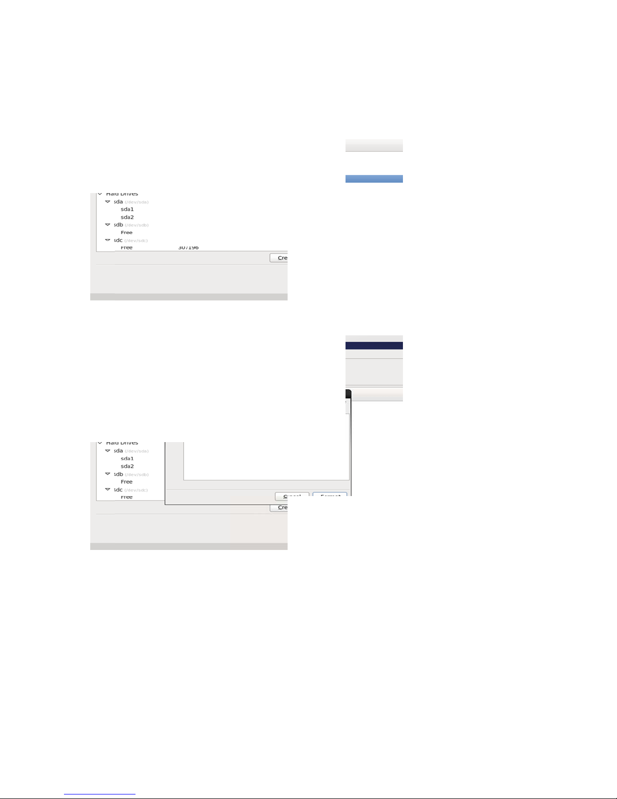
21. Click
22. Click
23. Whe
Next to initi
Write chang
the boot lo
te formatti
s to disk w
der operatin
g the hard d
en prompte
system list
ives, and cli
.
appears, cli
ck Format w
k Next.
hen asked to
confirm.
P
ge 21
Page 24
Dell DX O
t
n
t
e
e
t
i
m
t
r
T
w
i
t
e
p
e
e
o
o
e
m
y
m
d
g
w
e
s
c
ePa
a
k
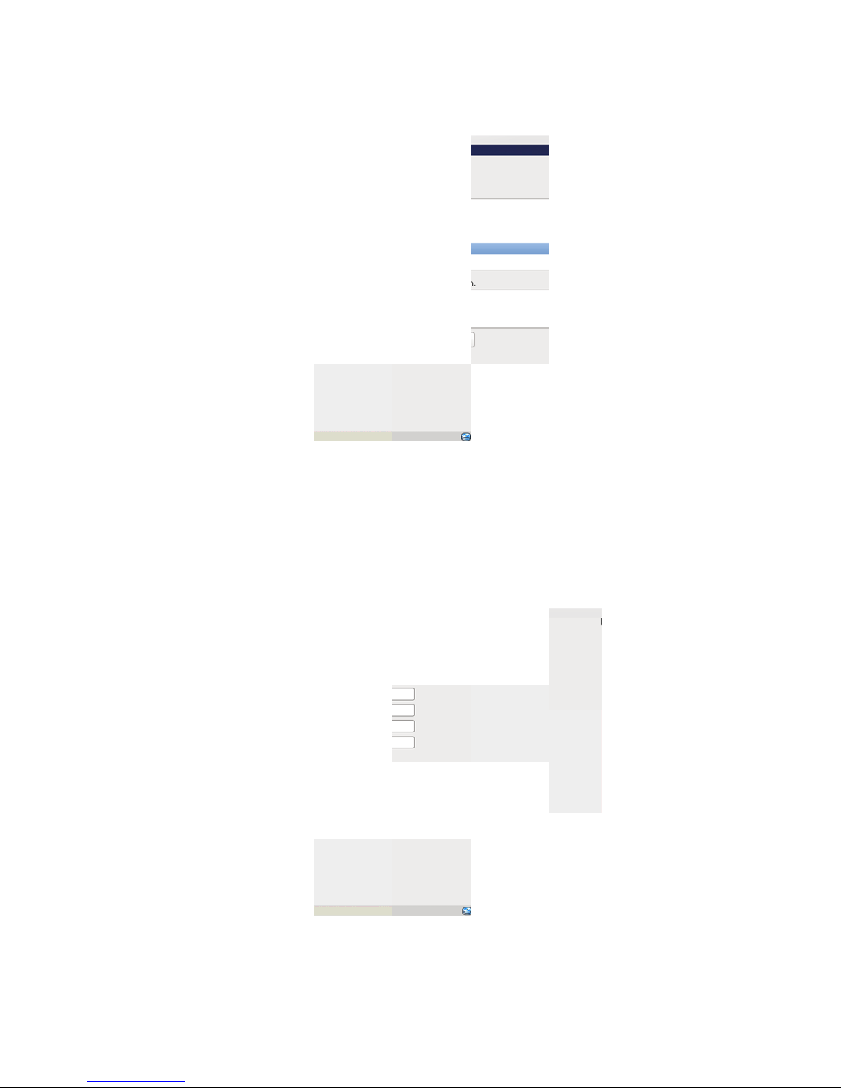
24. Selec
bject Storag
Desktop as
– File Gate
the installat
ay Deploym
on type and
nt Guide
click Next.
25. Click
26. After
27. Whe
Upda
28. In th
Next to star
the installat
the Welco
e screens.
Create Use
the installa
on complet
e screen ap
screen, ent
ion.
s, click Reb
ears, click F
r a Userna
ot when pro
rward to a
e, Full Nam
pted.
vance throu
e, and Pass
h the Licen
ord, and cli
e and Softw
k Forward.
re
29. On th
e Date and
and c
lick Forward
ime screen,
.
select the S
nchronize d
ata and tim
over the n
twork chec
box
ge 22
Page 25

Dell DX Object Storage – File Gateway Deployment Guide
30. On the Kdump screen uncheck the box.
31. Add the master boot record to the second boot drive.
Create the Master Boot Record (MBR) on the Second Drive
By creating a master boot record on a second logical volume, you can always ensure that the system is
bootable if a boot drive is removed, or – in the less predictable event – that the boot order is randomly
swapped by the operating system.
1. Open a terminal session and run the following command to determine which drive is the boot drive.
# df | grep boot
2. One of the following will display:
/dev/sda1 198337 30414 157683 17% /boot
OR
/dev/sdb1 198337 30414 157683 17% /boot
This is the device and partition the boot drive is on.
3. Run the following command to start grub.
# grub
4. Based on the information obtained about the boot drive, set up the master boot record. (This
example assumes that the command in step one discovered drive 0 as the boot drive.)
If the boot drive is sda, enter the following:
# grub> root (hd0,0)
Filesystem type is ext2fs, partition type 0x83
If the boot drive is sdb, enter the following:
# grub> root (hd1,0)
Filesystem type is ext2fs, partition type 0x83
5. Set up the first master boot record
Page 23
Page 26

Dell DX Object Storage – File Gateway Deployment Guide
# grub> setup (hd0)
Checking if "/boot/grub/stage1" exists... no
Checking if "/grub/stage1" exists... yes
Checking if "/grub/stage2" exists... yes
Checking if "/grub/e2fs_stage1_5" exists... yes
Running "embed /grub/e2fs_stage1_5 (hd0)"... 26 sectors are embedded.
succeeded
Running "install /grub/stage1 (hd0) (hd0)1+26 p (hd0,0)/grub/stage2
/grub/grub.conf"... succeeded
Done.
6. Set up the second master boot record
# grub> setup (hd1)
setup (hd1)
Checking if "/boot/grub/stage1" exists... no
Checking if "/grub/stage1" exists... yes
Checking if "/grub/stage2" exists... yes
Checking if "/grub/e2fs_stage1_5" exists... yes
Running "embed /grub/e2fs_stage1_5 (hd1)"... 26 sectors are embedded.
succeeded
Running "install /grub/stage1 d (hd1) (hd1)1+26 p (hd0,0)/grub/stage2
/grub/grub.conf"... succeeded
Done.
NEXT STEP: Disable SELinux
Disable SELinux
For the rest of the CFS setup process to work, you must disable SELinux.
1. Open the configuration file.
# cd /etc/selinux/
# vi config
2. Change the settings as follows to disable SELinux.
SELINUX=disabled
3. Reboot the system.
NOTE: Do not continue to configure the system until it has been rebooted.
Page 24
Page 27

Dell DX Object Storage – File Gateway Deployment Guide
NEXT STEP: Create the YUM Repository and Install Packages
Create the YUM Repository and Install Packages
The CFS installation process is dependent on additional rpm packages that are not installed on the
system by default. These packages are available on the Red Hat Enterprise Linux distribution media
included with the system. Running these packages requires a local YUM repository.
To create a local YUM repository on your system:
1. Ensure the CFS is powered on.
2. Insert the operating system media that came with the system into the optical drive and allow the
file system to auto mount.
The default directory path for the auto mounted file system is /media/RHELx.x\x86_64\ DVD. The
white spaces in this file path cause errors during the YUM setup process.
BEFORE YOU BEGIN: Did you Disable SELinux?
3. Create an .iso image of RHEL6.
# dd if=/dev/dvd of=RHEL-6.0_x86_64.iso
4. Create the yum repository.
# mkdir /root/RHEL6
# mount –o loop,ro /root/RHEL-6.0-x86_64.iso /root/RHEL6
NOTE: Do not use root as your yum repository. Create a designated folder for the repository (such as RHEL6 in
the example above).
NOTE: The mount must be recreated each time you reboot the system.
5. Remove any cached packages from the system and enable the local YUM repository.
# yum clean all
# yum repolist
6. Edit the repository to remove packagekit-media.repo.
# cd /etc/yum.repos.d
# rm packagekit-media.repo
# vi rhel6.repo
NOTE: The packagekit-media.repo file must be deleted each time you reboot the system.
7. Add the following to rhel6.repo file.
[InstallMedia]
Page 25
Page 28

Dell DX Object Storage – File Gateway Deployment Guide
d
name=Red Hat Enterprise Linux 6.0
mediaid=1285193176.460470
metadata_expire=-1
gpgcheck=0
cost=500
baseurl=file:/root/RHEL6
enabled=1
8.
Ensure that avahi-daemon is running.
# service avahi-daemon status
If avahi-daemon is not running, use the following command:
# service avahi-daemon restart
# chkconfig avahi-daemon on
9. Install the packages required to complete CFS installation.
a. Create a package list file.
# vi pkglist
b. Add the following services to the file.
ialog
libtdb
libldb
libtalloc
samba
samba-common
samba-client
samba-winbind
samba-winbind-clients
tdb-tools
ntpd
iscsi-initiator-utils
device-mapper-multipath
device-mapper-multipath-libs
NOTE: Check the spelling of each of the above entries carefully. Also, when installing the
packages, if any dependencies are identified, go ahead and install it now and repeat the
installation of any package that failed because of the dependency.
10. Run the following command:
# for pkg in ‘cat pkglist`
do
yum install $pkg --nogpgcheck
done
Page 26
Page 29

Dell DX Object Storage – File Gateway Deployment Guide
The CFS system is now ready to be updated with all the dependencies required to complete the
installation.
NEXT STEP: Stop and Disable Services
Page 27
Page 30

Dell DX Object Storage – File Gateway Deployment Guide
Stop and Disable Services
BEFORE YOU BEGIN: Did you Disable SELinux?
1. Create a list of file services.
# vi list
2. Add the following services to the file.
nscd
NetworkManager
nmb
smb
winbind
ntpd
nfs
iptables
ip6tables
3. Run the following command:
# for svc in ‘cat list`
do
service $svc stop
chkconfig $svc off
done
NEXT STEP: Set up the NTP Server
Set up the NTP Server
BEFORE YOU BEGIN: Did you Stop and Disable Services?
The CFS server(s) must use the same NTP time source as the domain controllers that will be used for
handling Active Directory-based credentials. Even when Active Directory is not used, it is still
recommended to use a common time source for all CFS servers.
NOTE: If you selected an NTP server while installing the operating system on the CFS, you do not need
to perform the following procedure.
1. Verify that ntpd is not running.
# service ntpd status
2. If NTP is running, stop the service.
Page 28
Page 31
Dell DX Object Storage – File Gateway Deployment Guide
k
k
k
k
k
k
k
# service ntpd stop
3. Edit the /etc/ntpd.conf file.
# vi /etc/ntpd.conf
4. Edit the file to configure the time server to your site time server as identified in the site survey
form.
server clock.xyz.project.local stratum 2
server time1.nis.gov stratum 1
IMPORTANT: Use only appropriate entries. If using external NTP servers, make sure you are authorized
to use those servers.
NOTE: The clock should be the time server of your Windows doma in controller server and is shared
between the Windows domain controller and the CFS server. It is very important that the time be set
within 5 seconds of datum (Atomic Clock time).
5. Restart the time service and configure autostart on reboot.
# chkconfig ntpd on
# service ntpd start
NEXT STEP: Configure the Network Interfaces for Bonding
Configure the Network Interfaces for Bonding
BEFORE YOU BEGIN: Did you Set up the NTP Server?
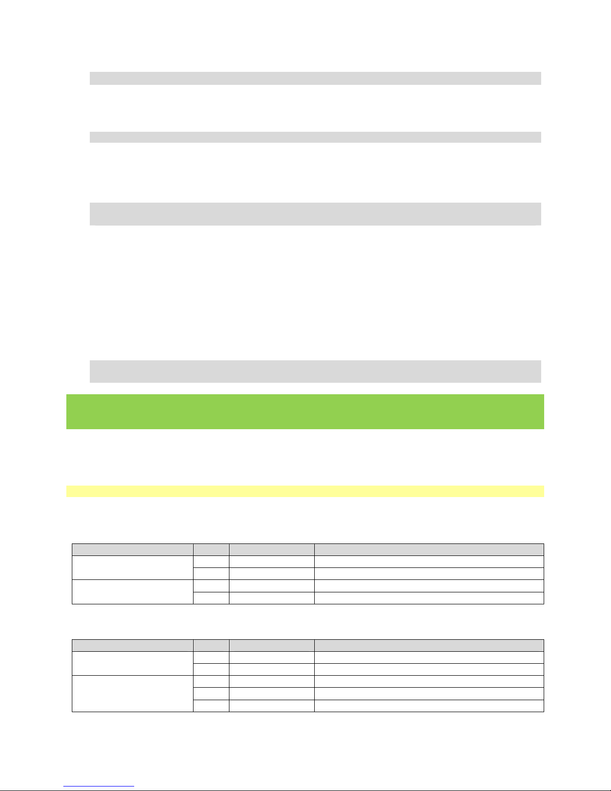
Channel bonding enables two or more network interfaces to act as one, simultaneously increas ing the
bandwidth and providing redundancy. Dell recommends the following bonds for the networks that are
part of the CFS solution.
Bond Ethernet ports Networ
Single-Server Solution
Failover Solution
NOTE: If iSCSI is on a separate network, use the following port designations.
Bond Ethernet ports Networ
Single-Server Solution
Failover Solution
0 0-1
1 2-5
0 0-1
1 2-5
0 0-1
1 2-5
0 0-1
1 2-3
2 4-5
CFS/NFS Gateway Network
DX Cluster Networ
CFS/NFS Gateway Network
DX Cluster Networ
CFS/NFS Gateway Network
DX Cluster Networ
CFS/NFS Gateway Network
DX Cluster Networ
iSCSI Storage Networ
and iSCSI storage
Page 29
Page 32

Dell DX Object Storage – File Gateway Deployment Guide
-
s
s
Dell supports two different types of bonding: balance-alb (adaptive load balancing) and link
aggregation control (LACP, also known as 802.3ad). Balance-alb is configured as mode=6; 802.3ad is
configured as mode=4. (see below). You should deploy the type of bonding that the customer site is
most comfortable with.
Configuration of Ethernet bonding under RHEL 6.0 requires the configuration of bond master files (one
per bond), and a configuration file for each of its slave ports.
NOTE: This procedure requires extensive information about the cust omer’s network. You should have
the completed Site Survey form readily available.
1. Change to the network-scripts directory.
# cd /etc/sysconfig/network
cript
2. Create interface configuration files (one required for each bonded network).
# vi ifcfg-bondn (where n is the bond number, beginning with 0)
3. Enter the following information in the file, replacing the network addresses with those used in your
network.
DEVICE=bond0
ONBOOT=yes
IPADDR=xxx.xx.x.xx (see Site Survey)
BOOTPROTO=none
PREFIX=24 (appropriate netmask significant bits from the Site Survey)
IPV6INIT=no
NAME="System bond0"
TYPE=Ethernet
GATEWAY=xx.xx.x.x (see Site Survey)
DEFROUTE=yes
IPV4_FAILURE_FATAL=yes
BONDING_OPTS="mode=6 miimon=100" (see Site Survey)
DNS1= xxx.xxx.xxx.xxx (see Site Survey).
DOMAIN=xyz.project.local (see Site Survey)
The next step defines the configuration for each of the Ethernet ports that are to be bonded.
4. Create a configuration file for the Ethernet port.
# vi ifcfg-ethn (where n is the NIC port
NOTE: The NIC port number and its MAC address can be obtained from /etc/udev/rules.d/70persistent-net.rules. This file identifies all of the NIC ports found when the system was last
powered on.
5. Enter the following information.
DEVICE="ethn" (where n is the number of the Ethernet port)
number, starting from 0)
Page 30
Page 33

Dell DX Object Storage – File Gateway Deployment Guide
k
ONBOOT=yes
HWADDR=00:26:B9:3D:55:19 (validate this against /etc/udev/rules.d/70-persistent-net.rules)
NAME="System ethn" (where n is the number of the Ethernet port)
BOOTPROTO=none
MASTER=bondx (where x is the number of the bond to which the Ethernet port belongs)
SLAVE=yes
USERCTL=no
6. Repeat the above steps for every Ethernet port, substituting the appropriate port number (e.g.,
eth1 port, replacing eth0 with eth1).
7. Repeat steps 2-5 for the remaining bond(s) and assigned Ethernet ports.
8. Load the kernel module to validate the channel bonding interfaces.
a. As root user, go to the /etc/modprobe.d directory.
b. Create a bonding.conf file.
c. In the bonding.conf file, insert the following lines:
alias bond0 bonding
alias bond1 bonding
NOTE: Add one entry for each bonded Ethernet interface that has been configured.
9. Restart network services
# service network restart
10. Reboot the system.
NEXT STEP: Configure the Domain Name Service Resolver
Configure the Domain Name Service Resolver
BEFORE YOU BEGIN: Did you Configure the Networ
A CFS Gateway requires an authoritative domain name server. Before beginning this procedure, obtain
the following information from Windows Active Directory Services:
Interfaces for Bonding?
Domain name
Domain name server IP address
Open the /etc/resolv.conf file.
# vi /etc/resolv.conf
Page 31
Page 34

Dell DX Object Storage – File Gateway Deployment Guide
1. Enter the following information in the resolv.conf file:
search xyz.project.local (see
nameserver xx.xx.x.x (see Site Survey)
domainname xyz.project.local (see Site Survey)
NOTE: Make sure there is a DNS entry for the CIFS/NFS interface of the server.
2. Edit the /etc/nsswitch.conf file.
# vi /etc/nsswitch.conf
3. Between the shadow: and networks: lines, you will find the following:
…
hosts: files dns
…-
Change this line to:
…
hosts: files dns mdns4_minimal [NOTFOUND=return] dns mdns4
…-
4. Restart network services.
# service network restart
Site Survey)
NEXT STEP: Install the CFS Software
Install the CFS Software
BEFORE YOU BEGIN: Did you Configure the Domain Name Service Resolver?
The caringo-cfs package is available as a Red Hat rpm package that is installed with a shell script. As
the root user, install the package and dependencies with the following command.
1. Verify that all services are stopped.
# service nscd status
# service smb status
# service nmb status
# service winbind status
# service nfs status
Page 32
Page 35

Dell DX Object Storage – File Gateway Deployment Guide
-
6.0-
x86_
NOTE: Services should show as not running for all of the above. If they are running, they must be
disabled.
NOTE: If any of these commands fail (other than saying that the service is not running), this indicates
that the required software package was not installed. See Create the YUM Repository and Install
Packages. Make sure the RHEL6 iso is still mounted. If it is not mounted, run the following command:
# mount –o loop,ro /root/RHEL
1. Copy the CFS installation zip file to /root and extract it.
2. Change directory to the newly extracted directory tree.
3. Install the CFS package.
# ./installDXCFS.sh
NEXT STEP: Create the Spooler and Cache File Systems
64.iso /root/RHEL6
Create the Spooler and Cache File Systems
The spooler is a shared file system that serves as a spool/cache for files before they are written to DX
Object Storage. The spooler also contains journals and file revision information. Depending on the
solution, the spooler can be on the CFS server itself (single-server solution) or on an external storage
device (failover solution).
As the spooler grows, unnecessary spooler entries are eventually evicted. Also, if the files are needed
for later reads, they will be accessed directly from the spooler, if the files are still on the spooler.
NOTE: Each CFS share must have its own dedicated spooler partition and its ow n cache
eviction/management process.
If the spooler partition is shared between CFS shares, there will be eviction conflicts between the
processes. Because of this restriction, some customers mount subfolders inside a single CFS share via
CIFS. You need to make a new CFS share for any of the following scenarios:
When you need to specify different lifepoint policies or custom metadata for the mount. For
example, PACS data has a retention period of 15 years, whereas emails are kept for 3 years. etc...
When your applications have different usage patterns ( lots of small files vs lots of very large file
transfers ). The spooler has a max files configuration set by default to 10 0000 , eviction is based on
partition used capacity as well as max files, this was added to prevent a 100Gb spooler partition
from filling up with 50M small files.
When you want to isolate the performance impact of your applications fro m each other
Page 33
Page 36

Dell DX Object Storage – File Gateway Deployment Guide
s
h
e
Example, customer was running a batch job that needed to quickly scan all files in a share for
viruses, would quickly flood the cache and evict files from another application running in the same
share (affecting read performance).
If the CNS cache must be installed on its own spooler file system.
Depending on your CFS configuration, you will need to create the spooler on a Dell PowerVault MD3200i
(failover CFS solution), or on the CFS File Server itself (single-server solution). Refer to the appropriate
section below.
Create disk partitions and spooler file systems (Single-server solution)
BEFORE YOU BEGIN: Did you Set up the CFS Server?
A local spooler on the CFS should have a capacity of 2TB (for SATA drives) or 600GB (for SAS drives) and
be configured as RAID 1.
1. Find the drive that the spooler will be residing on. Substitute for Drive_ID below the correct drive
ID. (Could be sda or sdb; run the #df to identify the disks.)
2. Dedicate a drive for the spooler.
# fdisk /dev/Drive_ID
Create a partition that spans the whole drive:
a. Type n and press <Enter> (to create a new drive)
b. Select the partition type by typing p (primary) and press <Enter>
c. Enter Partition number = 1.
d. For First cylinder use default 1.
e. Press <Enter> at ending partition = end of disk.
f. Type w (to write the partition).
3. Format the drive.
# mkfs.ext4 /dev/Drive_ID1
4. Create a mount point for the drive.
# mkdir -p /var/spool/cfs/
are_nam
5. Edit the /etc/fstab file.
# vi /etc/fstab
6. Add the following after the last line.
Page 34
Page 37

Dell DX Object Storage – File Gateway Deployment Guide
s
/sh
e
e
/dev/Drive_ID1 /var/spool/cf
are_nam
xt4 rw,acl,user_xattr,nodelalloc 1 20 0
7. Mount the file system.
# mount –a
8. Validate that the mount occurred.
# df | grep cfs
NEXT STEP: Configure the Cluster Name Space (CNS)
External Spooler File System (Failover solution)
The preferred external storage option (documented in this guide) is the MD3200i. However, many
installations may already have an external storage infrastructure in place. The CFS gateway can use
any external storage solution that meets the following criteria:
Access to the external storage is supported on RHEL 6; this includes consi d erations of
performance, availability, etc.
External storage supports creation of an ext3 or ext4 file system.
File system can be mounted (non-concurrently) on each gateway system.
External storage system is highly reliable (write operations performed to the external st orage
and returned as completed must actually be completed, they cannot be lost in e.g. power
failure, network outage, etc).
Connection to the external storage can be done either via the existing Ethernet adapter
configuration required for the gateway (in the case of e.g. iSCSI-based storage) or via another
connection that does not interfere with any connectivity required for the gateway (e.g. Fibre
Channel, SAS, etc). Ethernet-based storage may be located on any of the networks connected
to the gateway; choice of a network should take into consideration bandwidth requirements,
network addressing, etc.
NOTE: Configuration of non-MD3200i external storage is beyond the scope of this document; the
documentation for the external storage solution should be used for any required configuration.
Configure the MD3200i
BEFORE YOU BEGIN: Did you Set up the CFS Server?
The MD3200i spooler supports a minimum of six drives and a maximum of 20. The drives should be
configured as RAID5 with one hot-spare. You will also need to create a number of LUNs (logical disks).
The number of LUNs you should create is based on the number of CFS shares, maximum file size, and
performance requirements. You will need one LUN for the CNS cache and one for each CFS file system.
Page 35
Page 38

Dell DX Object Storage – File Gateway Deployment Guide
1. Cable the MD3200i as follows:
a. Connect the management ports on each controller to the public network.
b. Connect the data ports (4 on each controller) to the storage network.
2. Install the PowerVault Modular Disk Storage software (also known as MDCU) on a Windows or Linux
management station.
IMPORTANT: Do not install any Dell PowerVault Linux drivers.
NOTE: The management station should be separate from the CFS or CSN servers.
3. Run the management software and allow it to automatically discover storage devices.
NOTE: Autodiscovery assumes that the management station is on the same subnet of the public
network. If the Autodiscovery does not begin automatically when launching the application, select
Tools
Autodiscovery in the console.
4. Configure RAID arrays and virtual disks (LUNs).
a. Open the MD3200i management screen by double-clicking on storage array.
b. Click the Logical tab, right-click a disk, and click Create to configure the drives on the
MD3200i into a single RAID5 array, leaving one disk as hotspare.
c. Click the Logical tab, right-click an array, and click Create to configure the LUNs.
NOTE: Use essentially the same logic as you did for sizing the storage nodes on a DX
cluster when creating virtual disks in the shared spool. For example, if the customer has
larger file sizes, you should create larger LUNs. If you have reason to believe that the
customer may add additional CFS file systems in the future, you can create extra LUNs for
them to use when necessary, or leave unconfigured space for expansion.
5. Create a host group on the MD3200i for each failover node pair.
a. Mappings menu Define Host Group
b. Enter host group name and click OK.
6. Assign the LUNs you created to the host group with whatever LUN numbers are desired.
a. Expand Undefined Mappings, right click on the LUN and then select Define Additional
Mappings.
b. Select Host group or host.
c. Select LUN # and click Add.
7. Configure iSCSI on the MD3200i.
a. Setup tab.
b. Configure iSCSI Host Ports
c. IP address and subnet mask
d. Don’t need gateway
e. Select iSCSI host ports for other data ports and configure the same.
Page 36
Page 39

Dell DX Object Storage – File Gateway Deployment Guide
f. If VLAN, click Advanced IPv4 Settings and enter VLAN information.
g. Click OK.
h. Check Manage iSCSI Settings and Target Authentication set to None.
8. From a root login on the CFS node, ping all eight iSCSI IPs to ensure they are working.
9. Change the initiator name.
# iscsi–iname –p iqn.2010-12.local.project.xyz>> /etc/iscsi/initiatorname.iscsi
# vi /etc/iscsi/initiatorname.iscsi
When you open the file, you will see the following.
InitiatorName= iqn.1994-05.com.redhat:8072808d1ba6
iqn.2010-12.local.project.xyz:a82389cde897
10. Move the cursor to the first “I” of iqn (in the InitiatorName line), delete to the end of the line
(Shift+d), join the two lines (Shift+j), and delete the space between the = sign and the newly
generated iqn.
11. Start iscsid and iscsi.
# service iscsid restart
# service iscsi restart
12. Set iscsi and iscsid to start on boot
# chkconfig iscsid on
# chkconfig iscsi on
13. Discover the iSCSI ports.
# iscsiadm -m discovery -t st -p 172.16.16.30
The listing should show all iSCSI ports on the MD3200i.
14. Open the MD storage console to make the LUNs visible to the host:
a. Mappings tab.
b. Select the host group with the LUNs, and select DefineHost.
c. Enter a Host name.
d. Select Add by selecting a known unassociated host port identifier.
e. Select an entry from the known unassociated host port identifier drop-down list.
f. NOTE: Click the Refresh button if a host port does not initially appear in the list.
g. Enter a host name and Click Add, and click Next
h. Select Linux and then Finish.
This allows the host to see the LUNs; prior to this step all it could see was an ‘access
volume’, which is used for in-band management of the storage.
15. Retrieve the LUN information.
# iscsiadm -m discovery -t st -p 172.16.16.30
Page 37
Page 40

Dell DX Object Storage – File Gateway Deployment Guide
d
>
>
16. Run the following command to log the server into the storage, and create disks in /dev and mapper
entries for the multipath disk-mapper volumes.
# iscsiadm -m node –l
17. Display all LUNs in the host group.
# multipath –ll
All the LUNs in the host group should be displayed (Use size information to verify the correct LUNs
are displayed).
18. Run the following command to create a partition table where mpath<d> (e.g. mpathe) is one of the
LUN names that was shown when the multipath –ll command was run. This command will need to
be repeated for each LUN being used. Options used for the fdisk command should be the same as
those used below in step 2 of the single-server solution.
# fdisk /dev/mapper/mpath<
a. Create a partition that spans the whole drive:
i. Type n and press <Enter> (to create a new drive)
ii. Select the partition type by typing p (primary) and press <Enter>
iii. Enter Partition number = 1.
iv. For First cylinder use default 1.
v. Press <Enter> at ending partition = end of disk.
vi. Type w (to write the partition).
19. Run the following command to create a /dev/mapper entry for the new partition. This command
will need to be repeated for each LUN being used.
# kpartx -a /dev/mapper/mpath<d>
20. Create an ext4 file system on the partition.
This command will need to be repeated for each LUN being used. The mapper entry will generally
be of the form mpath<d>p1 (e.g. mpathep1).
# mkfs -t ext4 /dev/mapper/mpath<d
21. Add the LUNs to /etc/fstab. A number of lines will be added, of the form:
/dev/mapper/mpath<d>p1 /var/spool/cfs/cifs1 ext4 acl, user_xattr,nodelalloc,_netdev 1 20 0
The first entry should be for /var/cache/cns instead of /var/spool/cfs/cifs1. The name ‘cifs1’
should be chosen to correspond to the customer’s intended CFS names.
Page 38
Page 41

Dell DX Object Storage – File Gateway Deployment Guide
\
.
\
[0\]\
.
-
n ’
n
’
-
\
.
n
\[0\]\
.
22. After all LUNs are added to /etc/fstab, mount the new file systems.
# mount –a
23. Use ‘df’ to verify that all are mounted.
WARNING: Do NOT mount the drives on the backup node while the file system is mounted on the
primary node. This will cause the mount to fail and could even damage the file system. You must
unmount the file system from the primary drive BEFORE mounting the file system on the backup
node. Likewise, even after assigning a mount on the backup node (assuming you have unmounted
from the primary node), do NOT set it to automount.
24. Verify that /etc/iscsi/iscsid.conf has node.startup = automatic enabled.
# iscsiadm -m node -o show | egrep 'node
(name|conn
startup|startup)'
Expected output is as follows:
node.name = iqn.2010-12.local.project.xyz.cifs1
node.startup = automatic
node.conn[0].startup = manual
node.name = iqn.2010-12.local.project.xyz.cifs1
node.startup = automatic
node.conn[0].startup = manual
25. Set the iSCSI initiator to startup automatically at boot-time and login to the iSCSI targets at start-
up.
# iscsiadm -m node -o update
ode.conn[0].startup
v automatic
26. Validate that the new settings have been accepted by running following command (previously used
in the step above):
# iscsiadm -m node -o show | egrep 'node
(name|con
startup|startup)'
Expected output is as follows:
node.name = iqn.2010-12.local.project.xyz.cifs1
node.startup = automatic
node.conn[0].startup = automatic
node.name = iqn.2010-12.local.project.xyz.cifs1
node.startup = automatic
node.conn[0].startup = automatic
27. Restart the iscsi initiator service, and set it to run automatically by executing the following
commands.
# service iscsid stop
Page 39
Page 42

Dell DX Object Storage – File Gateway Deployment Guide
-
c
# service iscsi stop
# chkconfig iscsi --level 2345 on && chkconfig iscsi --list
# chkconfig iscsid --level 2345 on && chkconfig iscsid --list
# service iscsi start
# service iscsid start
# service multipathd start
28. Edit the Caringo startup scripts to make sure that CNS and CFS start in the proper order.
a. In the file /etc/init.d/caringo.cns, change the following:
# Required-Start: $networking $avahi $time
# Required-Stop: $networking $avahi $time
To
# Required-Start: $networking $avahi $time $remote_fs
# Required-Stop: $networking $avahi $time $remote_fs
b. In the file /etc/init.d/carinfo.cfs; change the following:
# Required-Start: $networking $avahi $time
# Required-Stop: $networking $avahi $time
To
# Required-Start: $networking $avahi $time caringo-cns
# Required-Stop: $networking $avahi $time caringo-cns
c. Run the following commands:
# chkconfig --del caringo
ns
# chkconfig --del caringo-cfs
# chkconfig --add caringo-cns
# chkconfig --add caringo-cfs
29. Edit the kernel configuration settings so that the iSCSI initiator is installed in the boot image.
# dracus --force
NOTE: If using CHAP authentication, you must change that information in this file to match what
was entered for the target.
30. Repeat these steps on the backup node.
Page 40
Page 43

Dell DX Object Storage – File Gateway Deployment Guide
IMPORTANT: Of the MD3200i configuration steps, only the one adding a host to the host group
need to be repeated. Do NOT repeat the fdisk and mkfs steps.
NEXT STEP: Configure the Cluster Name Space (CNS)
Configure the Cluster Name Space (CNS)
BEFORE YOU BEGIN: Did you Create the Spooler and Cache File Systems?
The file system structure, metadata, and DX Object Storage UUIDs are stored in a journaling name
space that stores file metadata into Dell DX Object Storage automatically. After installing the CFS
server, it is essential to configure a new name space. This is only required during installation;
subsequent CFS share definitions will not require a new name space.
NOTE: Ensure the DX Storage Cluster is online and reachable before configuring the new name space.
1. As the root user, run the following command:
# cns-admin
2. Complete the following values when prompted by the cns-admin utility:
Log facility – Enter the logging facility to use. The default value is syslog.
Log filename – If the file logging facility was selected, enter the filename and location
of the log file. By default the installer will use a /var/log/caringo/cns.log file. An
additional file in /var/log/caringo/cnsaudit.log will log the UUIDs for all successful DX
Object Storage deletes for audit purposes. With file logging, default log rotation for
Page 41
Page 44

Dell DX Object Storage – File Gateway Deployment Guide
both files will be configured to keep up to 8 log files, rotating weekly or at a max file
size of 512 MB.
Syslog facility – If the syslog option was selected, enter the facility to log to. The
default value is local1. Configuration of a remote syslog host must be done in the
syslogd configuration file.
Log level – Enter the minimum level of log messages to record. The default value is info.
Each log level includes the following:
info – errors, warnings and information messages like system start up and stop
verbose – errors, warnings, and info messages plus high-level operational functions
debug – errors, warnings, info and verbose messages plus lower level operational
functions
trace – all possible log messages
CNS host – The location of the name space server for the name space you are configuring. The
default is localhost (127.0.0.1), which will configure a name space on the local server. Enter an
external IP address, if using a remote server separate from the CFS server for the name space.
You can also enter a 0.0.0.0 address, if the name space must be created locally but needs to
connect to CFS shares on both the local server and remote servers.
DX Storage: use Zeroconf – Specify whether Zeroconf should be used to discover the list of
nodes in the Dell DX Object Storage cluster.
To use Zeroconf, the CNS must be in the same subnet with Dell DX Object Storage. If the CNS
must be located on a remote subnet, its address must be capable of routing to the subnet that
houses Dell DX Object Storage, and its address must be specified.
If you select No, complete the following:
Cluster primary node address – IP address or hostname for a Dell DX Object Storage
node in the target cluster. The target cluster must be the same as the one configured
for all CFS mounts.
Primary node SCSP port – the port the Dell DX Object Storage node uses for SCSP
communications. The default is 80.
Cluster secondary node address – the IP address or hostname for a second Dell DX
Object Storage node in the target cluster for redundancy. The target cluster must be
the same as the one configured for all CFS mounts.
Secondary node SCSP port – the port of the secondary DX Object Storage node uses for
SCSP communications. The default is 80.
NOTE: Primary and secondary DX Object Storage node addresses should be ma naged
through the site DNS server. Sites that use Microsoft Active Directory should use the
DNS server that is authoritative for the AD zone that the CFS server will join.
Page 42
Page 45

Dell DX Object Storage – File Gateway Deployment Guide
If you select Yes, complete the following:
Cluster name – name of the Dell DX Object Storage cluster. This must match the value
of the Dell DX Object Storage "cluster" parameter in the node.cfg file and be the same
target cluster as the one configured for all CFS mounts.
NOTE: If a cluster name is already present, use the <Backspace> key to eras e the
name and enter a new one.
Do you want me to email you the Root UUID for CNS? –The root id is critical to recovering the
name space in the event of a name space server failure and should be saved in a safe location.
The email function only works with SMTP servers that do not require authentication.
If you answer Yes, complete the following:
SMTP email server – SMTP email server that should be used to send the email. For
example, mail.host.com. A mail account of 'admin' at the specified mail server is
assumed (i.e. [email protected]) as the sending account. Mail servers withou t an
admin account will not be able to send the root uuid email.
Your email address – The email address to which the root id should be sent. For
example, [email protected].
NOTE: Administrators who experience email send errors should consult
/var/log/caringo/smtp.log.
If you answer No, the utility will confirm that a new root id for the name space has been
created with a message similar to the following:
Generated New Root Anchor [f223011d1fa56f67cf79a87a5de45901]
NOTE: If the configuration utility detects that a root id already exists it will ask you if you
would like to create a new one. Answering 'yes' to this question will create a new root and
delete all local CFS state information (spool, cache, etc.), as you will not be able to access the
information in the shares once the name space root has chang ed. The configuration files for
all shares will remain intact. You must stop CFS and CNS prior to attempting to create a new
root id.
The script will ask if you would like CNS to be started once you confirm the root id. 'Yes' is
recommended as a functioning namespace is required for CFS configuration. The created configuration
file will be located in: /opt/caringo/fabric/etc/cns.conf. Manual editing of this file is not
recommended unless directly advised by your technical support contact.
NOTE: The name space must remain online at all times to ensure CFS can obtain the needed file
system information. If CFS cannot connect to the name space, it will send permission denied errors
and block new file writes.
NEXT STEP: Configure the CFS and its DX Object Storage Mount Points
Page 43
Page 46

Dell DX Object Storage – File Gateway Deployment Guide
Configure the CFS and its DX Object Storage Mount Points
BEFORE YOU BEGIN: Did you Configure the Cluster Name Space (CNS)?
After installing the CFS server and creating the name space via cns-admin, you need to configure a
mount point for journal logging and Dell DX cluster information.
1. As the root user, run the following command:
# cfs-admin mkfs -–add
This will prompt you for the minimum parameters required to run CFS. Most fields have a default
value with the exception of fields that require your input, which will be blank.
To stop the configuration process at any time, use <Ctrl-C>; no configuration files will be created
until the utility completes successfully. The utility can be run multiple times if you are creating
multiple CFS mount points.
Each mount point must have its own unique name and configuration file. All created configuration
files will be located in /opt/caringo/fabric/etc/share_name.conf
NOTE: Manual editing of this file is not recommended unless under direct advice from a Dell
technical support contact.
2. Complete the following information:
ID to be used for this mount – Enter a name for the mount point. It must be unique on each server
and consist of letters and numbers without punctuation or spaces. For example, acctShare or
archiveFS.
Mount directory path – Enter the location of the mount point. By default, the utility will use the
previously provided mount ID in the /mnt directory. Spaces in mount point paths are not
supported.
Spooler directory path – Enter the location where the spooler/cache directory will reside. The
location must be unique for each distinct read/write mount ID, or the file system mount will fail.
By default, the installer will use the previously provided mount ID in the /var/spool/CFS directory.
Extended attributes must be enabled on the specified spooler partition to store the lifepoints and
custom and system metadata associated with each unspooled item.
NOTE: A dedicated spooler partition is required for each share to ensure space monitoring is
accurate and the local cache is properly maintained.
Mount read-only – Determines whether or not this CFS file system should be mounted in read-only
mode. The default value is No.
Log facility – Enter the logging facility to use. The default value is syslog.
Log filename – If the file logging facility was selected, enter the filename and location of the
log file. By default the installer will use a share_name.log file in the /var/log/caringo
Page 44
Page 47

Dell DX Object Storage – File Gateway Deployment Guide
directory. With file logging, default log rotation will be configured to keep up to 8 log files,
rotating weekly or at a max file size of 512 MB.
Syslog facility – If the syslog option was selected, enter the facility to log to. The default value
is local4. Configuration of a remote syslog host must be done in the syslogd configuration file.
Log level – Enter the minimum level of log messages to record. The default value is info. Each log
level includes the following:
• info – errors, warnings and information messages like system start up and stop
• verbose – errors, warnings, and info messages plus high-level operational functions
• debug – errors, warnings, info and verbose messages plus lower level operational functions
• trace – all possible log messages
CNS Host – IP address or hostname of the name space server that will store the file system
metadata for the mount you are configuring. The default is localhost (127.0.0.1), which will
configure the share to use a name space on the local server. To use a name space configured on a
remote server, enter the external IP address for the previously created name space.
NOTE: If configuring a multi-server environment where more than one CFS server is sharing a
single CNS instance, you must enter the same CNS host information that was entered in the cnsadmin utility for each share. A unique serial number will be generated for every created CFS share
for internal use when requesting exclusive file locks across all servers in the name space. This
serial number is stored with the CFS configuration files so they must not be copied from one
server to another to ensure the CFS share serial number is not duplicated.
CFS Time Horizon: (Default=0d means not Timecapes. Select OK for the default (0d)
Use Zeroconf for CFS configuration? – Specify whether Zeroconf should be used to discover the list
of nodes in the Dell DX Object Storage cluster. The CFS server must be in the same subnet as the
Dell DX Object Storage cluster to use Zeroconf.
If No is selected, provide the following information:
Dell DX Object Storage cluster primary address – IP address or hostname of a Dell DX
Storage node in the target cluster. The target cluster must be the same as the one
configured for the Content Name Space (CNS).
Dell DX Object Storage primary SCSP port – Port the Dell DX Object Storage node uses for
SCSP communications. The default is '80'.
Dell DX Object Storage cluster secondary address – IP address or hostname of a second
Dell DX Object Storage node in the target cluster for redundancy. The target cluster must
be the same as the one configured for the Content Name Space (CNS).
Dell DX Obje
ct Storage secondary SCSP port – Port the secondary Dell DX Object Storage
node uses for SCSP communications. The default is '80'.
If Yes is selected, provide the following information:
CASstor cluster name – Name of the Dell DX Object Storage cluster. This must match the
value of the Dell DX Object Storage "cluster" parameter in the node.cfg file and be the
same as the one configured for the Content Name Space (CNS). The cluster name is also
displayed on the Cluster Services Node management GUI.
Page 45
Page 48

Dell DX Object Storage – File Gateway Deployment Guide
3. If the Spooler/cache and mount directories do not already exist, you will be asked if you would like
them to be created.
The recommended response is Yes, as CFS cannot start without these directories. You will also be
asked if you want to mount the configured mount point immediately. The recommended response
is Yes.
4. After installing CFS initially, run the following command to start the CFS monitoring process.
# /etc/init.d/caringo-cfs restart
A restart is recommended so any processes can stop, if they are already running. This process will
start automatically on subsequent reboots.
NOTE: If you attempt to start CFS without first starting the Content Name Space, the
initialization will fail after 60 seconds. This may leave the file system mounted without a name
space. To unmount the file system, execute the following command and then start Content Name
Space and CFS sequentially:
# fusermount -uz /mnt/mountname
NEXT STEP: Configure Gateway Protocols
Configure Gateway Protocols
BEFORE YOU BEGIN: Did you Configure the CFS and its DX Object Storage Mount Points?
In addition to being able to write to a locally mounted Linux file system, the CFS platform design
makes it possible to layer network file services over the Dell DX Object Storage mounted file system
using any software that makes basic operating system calls to acces s a file system.
The CFS implements a SMB/CIFS protocol gateway to the Dell DX Object Storage platform, and also an
NFS protocol gateway. This section explains how these two gateway services can be configur ed in two
stages:
1) Configuring the protocol gateway service
2) Adding CIFS/NFS shared storage resources.
SMB/CIFS Gateway Service
CFS SMB/CIFS protocol gateway services can be configured either manually or using the CFS-admin cifsserver utility. The CFS-admin tool can be used to configure the CFS server either as a stand-alone
server that performs purely local authentication, or as a member of a M icrosoft Active Directory
security domain.
Page 46
Page 49

Dell DX Object Storage – File Gateway Deployment Guide
NOTE: A customer’s gateway can be configured only as standalone (local authentication) server OR as
an Active Directory Domain member server. It cannot be configured as both; it must be one or the
other.
Where configured as an Active Directory (AD) member, you can set file and directory access
permissions using Microsoft Windows ACLs. This requ ires support for POSIX ACLs in the underlying file
system.
The procedures outlined in this section cover only the configuration of the mode of service that the
SMB/CIFS protocol gateway will provide. Configure shares so that M icrosoft Windows workstations and
servers can access Dell DX Object Storage resources.
Stand-alone Server (Workgroup Authentication)
NOTE: A customer’s gateway can be configured only as standalone (local authentication) server OR as
an Active Directory Domain member server. It cannot be configured as both; it must be one or the
other.
BEFORE YOU BEGIN: Did you Configure the CFS and its DX Object Storage Mount Points?
Microsoft Windows SMB/CIFS networking makes heavy use of name-to-IP address resolution methods.
The older methods use NetBIOS (Network Basic Input/Output System) over TCP/IP technologies and
depend either on UDP broadcasts-based name resolution processes, or use WINS (Windows
Internetworking Name Service). Newer methods depend on DNS.
NOTE: Where the CFS SMB/CIFS server is configured to operate as a standalone server (i.e.: makes use
of local authentication) it is highly recommended to use both WINS and DNS, but at least one of
these (WINS or DNS) must be correctly configured.
1. Run the following command to save the original /etc/samba/smb.conf file.
#mv /etc/samba/smb.conf /etc/samba/smb.conf.orig
2. Run the following command to open the /etc/samba/smb.conf file.
#vi /etc/samba/smb.conf
3. Replace the workgroup name MYGROUP and the netbios name names (in upper case characters –
each max 14 characters) that are appropriate for the site:
[global]
workgroup = MYGROUP
netbios name = CIFSFS
server string = DX Storage
log level = 1
log file = /var/log/samba/log.%L.%m
max log size = 0
load printers = No
disable spoolss = Yes
os level = 0
posix locking = No
Page 47
Page 50

Dell DX Object Storage – File Gateway Deployment Guide
NOTE: If the site uses a WINS server, add the following to the above:
wins server = 123.45.67.89
(where 123.45.67.89 should be replaced with the IP address of the WINS server for the site)
3. Start the Samba daemons in preparation for the final CFS resource configur ation.
a. From a root login shell, run these commands to set smbd and nmbd to start automatically at
boot time:
# chkconfig smb on
# chkconfig nmb on
b. Start the server daemons by running the following commands:
# service nmb start
# service smb start
c. Verify that the daemons are running as shown here:
# ps ax | grep mbd
8099 ? Ss 0:00 smbd -D
8113 ? Ss 0:01 nmbd -D
8139 ? S 0:00 smbd -D
...
4. Create an administrative account for the local SMB/CIFS server, using either the root account
(easiest) or a normal user account.
This can be done two ways:
using the root account (simplest)
using a normal user account and then setting up User Rights and Privileges
Either of these enables a suitable user who can administer the Linux environment as exposed to the
MS Windows SMB/CIFS network environment.
a) Configure root as the MS Windows administrator equivalent by running the following
command and completing the required information as prompted:
# smbpasswd -a root
New SMB password: xxxxxxxxxx
Retype new SMB password: xxxxxxxxx
Added user root.
b) Configure the local administrator account.
NOTE: You must set up an administrator account. Also, all user names, including
administrator should be in lower-case, as Linux is case-sensitive.
i. Complete step a.
Page 48
Page 51

Dell DX Object Storage – File Gateway Deployment Guide
a
d
a
d
a
d
d
r
NOTE: This account will be removed or disabled after the administrator account has
been established.
ii. Create a Linux account as follows:
# useradd -m -g 4
ministrator
# passwd administrator
Enter new UNIX password: xxxxxxxxx
Retype new UNIX password; xxxxxxxx
Passwd: password updated successfully
iii. Add SMB/CIFS credentials as follows:
# smbpasswd -a
ministrator
New SMB password: xxxxxxxxx
Retype new SMB password: xxxxxxxxx
Added user administrator.
iv. Verify that the administrator account exists in the SMB/CIFS environment by
running the following command and viewing its ouput:
# pdbedit -Lv
ministrator
Unix username: administrator
NT username:
Home Directory: \\CIFSFS\administrator
HomeDir Drive:
Logon Script:
Profile Path: \\CIFSFS\administrator\profile
Domain: CIFSFS
Account desc:
Workstations:
Munged dial:
Logon time: 0
Logoff time: 9223372036854775807 seconds since the Epoch
Kickoff time: 9223372036854775807 seconds since the Epoch
Password last set: Tue, 21 Sep 2010 09:30:00 CDT
Password can change: Tue, 21 Sep 2010 09:30:00 CDT
Password must change: never
Last bad password: 0
Bad password count: 0
Logon hours: FFFFFFFFFFFFFFFFFFFFFFFFFFFFFFFFFFFF
v. Set administrator privileges for this account as shown here:
# net rpc rights grant “CIFSFS\administrator” SeMachineAccountPrivilege
SeTakeOwnershipPrivilege SeBackupPrivilege SeRestorePrivilege
SeRemoteShutdownPrivilege SePrintOperatorPrivilege SeAddUsersPrivilege
SeDiskOperatorPrivilege -Uroot%xxxxxxxxx
vi. Disable the root account by running the following command:
# smbpasswd -
oot
Disabled user root.
Page 49
Page 52

Dell DX Object Storage – File Gateway Deployment Guide
–
x
e
e
vii. Delete the root account from the CIFS password back end by running the following
command:
# pdbedit -u root
5. Add a local UNIX group, which is required for shared resource ownership and access control.
6. For each group identity (at least one is required) create a UNIX group and then map it into the
SMB/CIFS environment as shown here:
# groupadd engineers
# net groupmap add unixgroup=engineers ntgroup=engineers type=local
Replace engineers with an appropriate group name for the site.
7. Add local SMB/CIFS user accounts.
a. For each separate user who requires read-only access to the SMB/CIFS server, add a UNIX used
account and then create the SMB/CIFS account extensions as shown here:
# useradd -m -g users mynam
# passwd myname
Enter new UNIX password: xxxxxxxxx
Retype new UNIX password: xxxxxxxxx
Passwd: password updated successfully
# smbpasswd -a myname
New SMB password: xxxxxxxxx
Retype new SMB password: xxxxxxxxx
Added user Administrator.
b. For each separate user who requires read/write to access the SMB/CIFS server add a UNIX used
account and then create the SMB/CIFS account extensions as shown here and provide the
required information. The -G argument specifies that the user is assigne d to a secondary group.
# useradd -m -g users mynam
# usermod -a -G engineers myname
# passwd myname
Enter new UNIX password: xxxxxxxxx
Retype new UNIX password: xxxxxxxxx
Passwd: password updated successfully
# smbpasswd -a myname
New SMB password: xxxxxxxxx
Retype new SMB password: xxxxxxxxx
Added user Administrator.
IMPORTANT: User accounts created in Linux and Unix are case-sensitive and case-
preserving. Create accounts using only lower-case characters.
8. Configure the shared resources. See Configure Share Resources.
Page 50
Page 53

Dell DX Object Storage – File Gateway Deployment Guide
NEXT STEP: Configure Share Resources
Active Directory Domain Member Server
NOTE: A customer’s gateway can be configured only as standalone (local authentication) server OR as
an Active Directory Domain member server. It cannot be configured as both; it must be one or the
other.
BEFORE YOU BEGIN: Did you Configure the CFS and its DX Object Storage Mount Points?
Active Directory configuration requires the following procedures.
SMB configuration
NTP configuration
Edit the krb5.conf file
Edit the nsswitch file
Join the domain
Validate that the domain has been joined
Microsoft Active Directory requires a fully functional DNS service to resolve machine names and identify
critical services that enable or support Active Directory. The use of WINS (Windows Internetworking
Name Server) is NOT necessary with Active Directory – in fact, larger sites mostly disable the use of
NetBIOS over TCP/IP, thus nullifying the use of WINS.
DNS servers used with the CFS server should use the DNS server that is authoritative for the Active
Directory domain when configured as an Active Directory domain member server.
NOTE: In the examples shown in this section, the following names are used:
Active Directory domain controller = w2k8r2.xyz.project.local
Realm name = xyz.project.local
Windows machine name = W2K8R2
Pre-Windows 2000 domain name = XYZ
Edit the krb5 File
IMPORTANT: Do NOT edit the /etc/krb5.conf file on a standalone server. This file must be edited only
on an Active Directory domain member server.
The /etc/krb5.conf file must contain the correct domain name information for SMB to install
successfully.
1. Run the following command to open the /etc/krb5.conf file.
Page 51
Page 54

Dell DX Object Storage – File Gateway Deployment Guide
# vi /etc/krb5.conf
2. Edit the file as shown with your domain name information.
[libdefaults]
default_realm = XYZ.PROJECT.LOCAL
[realms]
XYZ.PROJECT.LOCAL = {
kdc = xxx.xxx.x.xx (AD DNS server; see Site Survey)
kdc = w2k8r2.xyz.project.local
}
NEXT STEP: Configure the SMB/CIFS Server
Configure the SMB/CIFS Server
BEFORE YOU BEGIN: Did you Edit the krb5 File?
1. Run the following command to open the /etc/resolv.conf file.
#vi /etc/resolv.conf
2. Set the CFS DNS server address to the authoritative DNS server for the Active Directory domain
as shown here:
domain xyz.domain.local
search xyz.domain.local other.dns.domain
nameserver xxx.xxx.x.xx
Where xyz.domain.local is the fully qualified DNS name for the Active Directory realm, the
address xxx.xxx.x.xx should be replaced with the correct IP address for the Active Directory
DNS server.
NOTE: The Network Time Protocol service on the CFS server should be configured using eith er
using the Microsoft Active Directory domain controller for the domain it will be joining, or
using the same time server it has been set up to use.
3. In the file /etc/samba/smb.conf, replace the workgroup name AD, the realm name, and the
netbios name (in upper case characters – each max 14 characters) that is appropriate for the
site:
[global]
workgroup = XYZ
realm = XYZ.PROJECT.LOCAL
netbios name = CIFSFS
Page 52
Page 55

Dell DX Object Storage – File Gateway Deployment Guide
server string = DX Storage
security = ADS
log level = 1
log file = /var/log/samba/log.%L.%m
max log size = 0
smb ports = 445
machine password timeout = 0
load printers = No
disable spoolss = Yes
os level = 0
ldap ssl = no
idmap backend = tdb
idmap uid = 5000000-10000000
idmap gid = 5000000-10000000
winbind separator = +
winbind cache time = 3000
winbind enum users = Yes
winbind enum groups = Yes
idmap config XYZ : backend = rid
idmap config XYZ : range = 100000 - 2999999
posix locking = No
NOTE: A non-overlapping Idmap config entry should be added for each trusted domain that must
access this server. The domain range must not clash or overlap with the Idmap UID and GID range and
the Idmap config range specified in the example of the XYZ domain shown above.
4. Join the domain as shown here:
# net xyz join -Uadministrator%xxxxxxxxx (where xxxx is password)
Using short domain name -- XYZ
Joined 'CIFSFS' to realm 'xyz.project.local'
…
5. Start the CFS SMB/CIFS server daemons as shown here:
# chkconfig winbind on
# chkconfig smbd on
# service winbind on
# service smbd on
6. Check the integrity of the domain trust account.
# wbinfo –t
checking the trust secret via RPC calls succeeded
7. Run the following command to obtain a list of Active Directory domain user accounts:
# wbinfo –u
XYZ+administrator
XYZ+guest
XYZ+krbtgt
XYZ+jthorely
Page 53
Page 56

Dell DX Object Storage – File Gateway Deployment Guide
XYZ+jackb
8. Run the following command to obtain the list of Active Directory domain group accounts:
# wbinfo –g
XYZ+domain computers
XYZ+domain controllers
XYZ+schema admins
XYZ+enterprise admins
XYZ+cert publishers
XYZ+domain admins
XYZ+domain users
XYZ+domain guests
XYZ+group policy creator owners
XYZ+ras and ias servers
XYZ+allowed rodc password replication group
XYZ+denied rodc password replication group
XYZ+read-only domain controllers
XYZ+enterprise read-only domain controllers
XYZ+dnsadmins
XYZ+dnsupdateproxy
9. Edit the file /etc/nsswitch.conf.
Edit the entries:
passwd: file
shadow: file
group: file
to the following:
passwd: file winbind
shadow: file winbind
group: file winbind
10. Obtain a list of users via the NSS interface:
# getent passwd
root:x:0:0:root:/root:/bin/bash
daemon:x:1:1:daemon:/usr/sbin:/bin/sh
bin:x:2:2:bin:/bin:/bin/sh
sys:x:3:3:sys:/dev:/bin/sh
sync:x:4:65534:sync:/bin:/bin/sync
...
statd:x:116:65534::/var/lib/nfs:/bin/false
XYZ+administrator:*:5000000:5000000:Administrator:/home/XYZ/administrator:/bin/false
XYZ+guest:*:5000001:5000001:Guest:/home/XYZ/guest:/bin/false
XYZ+krbtgt:*:5000002:5000000:krbtgt:/home/XYZ/krbtgt:/bin/false
XYZ+jthorely:*:5000003:5000000:John H. Thorely:/home/XYZ/jthorely:/bin/false
XYZ+jackb:*:5000004:5000000:Jack B. Black:/home/XYZ/jackb:/bin/false
Page 54
Page 57

Dell DX Object Storage – File Gateway Deployment Guide
11. Obtain a list of groups:
# getent group
root:x:0:
daemon:x:1:
bin:x:2:
sys:x:3:
...
XYZ+domain computers:x:5000006:
XYZ+domain controllers:x:5000007:
XYZ+schema admins:x:5000008:XYZ+administrator
XYZ+enterprise admins:x:5000009:XYZ+administrator
XYZ+cert publishers:x:5000010:
XYZ+domain admins:x:5000011:XYZ+administrator
XYZ+domain users:x:5000000:
XYZ+domain guests:x:5000001:
XYZ+group policy creator owners:x:5000012:XYZ+administrator
XYZ+ras and ias servers:x:5000013:
XYZ+allowed rodc password replication group:x:5000014:
XYZ+denied rodc password replication group:x:5000015:XYZ+krbtgt
XYZ+read-only domain controllers:x:5000016:
XYZ+enterprise read-only domain controllers:x:5000017:
XYZ+dnsadmins:x:5000018:
XYZ+dnsupdateproxy:x:5000019:
XYZ+unixgroup:x:5000020:XYZ+jthorely
12. Validate the domain membership information:
# net ads info
LDAP server: 172.16.10.27
LDAP server name: w2k8r2.xyz.project.local
Realm: XYZ.PROJECT.LOCAL
Bind Path: dc=XYZ,dc=PROJECT,dc=LOCAL
LDAP port: 389
Server time: Mon, 20 Sep 2010 21:51:32 CDT
KDC server: 172.16.10.27
Server time offset: 0
13. Copy the contents of the /var/run/samba/smb_krb5/krb5.conf.ADS file to the file
/etc/krb5.conf.
It should contain similar information as shown here:
[libdefaults]
default_realm = XYZ.PROJECT.LOCAL
default_tgs_enctypes = RC4-HMAC DES-CBC-CRC DES-CBC-MD5
default_tkt_enctypes = RC4-HMAC DES-CBC-CRC DES-CBC-MD5
preferred_enctypes = RC4-HMAC DES-CBC-CRC DES-CBC-MD5
Page 55
Page 58

Dell DX Object Storage – File Gateway Deployment Guide
[realms]
XYZ.PROJECT.LOCAL = {
kdc = 192.168.1.22
kdc = w2k8r2.xyz.project.local
}
The CFS server is now ready for configuration of shared resources. See Configure Share Resources.
NEXT STEP: Configure Share Resources
NFS Gateway Service
The procedures in this section define how to configure services so that shared resources can be added
using the appropriate procedure detailed in the Shared Resource Configuration section of this
document. The CFS file system resource can be accessed from a remote UNIX or Linux machine via the
NFS version 3.
NOTE: Dell does not support NFS version 4 at this time.
The following procedure configures NFS server only. After performing the procedure, you must then
configure shared resources. See Configure Share Resources.
Before Configuring NFS
To configure NFS, you must ensure that IP forwarding and the firewall are disabled.
Disable IP forwarding
By default, RedHat Linux has IP Forwarding disabled. To verify this, run the following command.
# sysctl net.ipv4.ip_forward
The command returns a value of 0, if IP forwarding is disabled, or 1 if it is enabled. IP forwarding
should be disabled following the procedures in the RHEL6 documentation.
Configure NFS to share the CFS mount
NFS must be configured to share the CFS mount. The configuration installed includes NFS kernel
support. Configure the NFS /etc/exports file as shown in the Configure Share Resources section. Do not
forget to turn the NFS service on and to start it. See the Configure Share Resources document for more
information.
NEXT STEP: Configure Share Resources
Configure Share Resources
Share resources provide the connection points for the SMB/CIFS and NFS protocol gateway services that
are provided by the CFS server. Each connection protocol has its own conf iguration requirements.
These have been integrated into the CFS-admin utility.
Page 56
Page 59

Dell DX Object Storage – File Gateway Deployment Guide
s
h
Administrators can configure the shared resources manually outside of the Dell-supported resources,
but it is without Dell support.
IMPORTANT: CFS mounts created by cfs-admin cannot persistently store ownership and permission
settings. For example, when the owner and group of the /mnt/share_name resource is changed from
the default (root, root) and/or the permissions of the mount are changed from the default to some
other preferred security setting, the changes will not persist if the CFS resource is dismounted and
remounted. The original default settings will prevail. To work around this limitation, create a folder
(directory) inside the mount point that will become the root of the CIFS and/or NFS share. Ownership
and permission settings on that folder will remain persistent.
SMB/CIFS Shared Resource Configuration
Specific configuration requirements of SMB/CIFS shared resources on a CFS server depend on whether
the server is configured for local authentication or as a member server in an Microsoft Windows Active
Directory security context (domain).
BEFORE YOU BEGIN: Did you set up Stand-alone Server (Workgroup Authentication)?
Add a Share (Standalone Server)
IMPORTANT: Make sure that the system is configured as Standalone Server. Do not continue with this
procedure if the system is not a Standalone Server.
1. Run the following command to open the /etc/samba/smb.conf file.
#vi /etc/samba/smb.conf
2. Add a share stanza to the file as shown here:
[share_name]
comment = Share1
path = /mnt/share_name/toplevel
read only = No
use sendfile = Yes
NOTE: Replace the share_name with an appropriate name. Dell recommends using the sa me
name as was used to create the CFS mounted resource. The toplevel directory must be created
within the CFS mount point because it creates the share-point for CIFS and NFS use.
3. Create the toplevel directory.
# mkdir –p /mnt/share_name/toplevel
4. Set file system ownership and group ownership for the user and group that will have write access to
the shared resource.
# chown –R myname:users /mnt/
# chmod –R ug+rw,o-rwx /mnt/share_name/toplevel
# find /mnt/share_name/toplevel –type d –exec chmod g+sx {} \;
are_name/toplevel
Page 57
Page 60

Dell DX Object Storage – File Gateway Deployment Guide
In the example above, there is a CFS mounted file system resource under the mount point
/mnt/share_name. The contents of this directory will be owned by the user gillian and the
group Users.
NOTE: Setting the SGID flag on directories enforces inheritance of group ownership of the toplevel directory as new files and directories (folders) are created.
NOTE: A read-only account can be a member of the same group that has write access to the
share. The read-only user account can have write permissions in the file system; this account
will be granted read-only access through ACL settings on the share itself. This is completed in
the following step.
5. Using a Microsoft Windows workstation or server (XP or later), set the share AC L.
a) Open a CMD terminal session. Run the following:
C:\Users\Administrator> net use * /d
…
Do you want to continue this operation? <Y/N> [N]: y
The command completed successfully.
If you are asked to continue the operation, answer Yes (see above).
This disconnects all open connections to remote systems. This is important in order to avoid
the side effect of open connections that can impede the ability to access security objects on
the remote system.
b) Launch Windows Explorer and type \\NetBIOS name of the CFS server (for example,
\\CIFSFS) and press <Enter>.
Windows Security will display for authentication.
i. Type in the NetBIOS name of the server and the administrator password (for
example CIFSFS\administrator)
ii. In the Password field, enter the password that you created for the administrator
account on the CFS server.
iii. Press <Enter>.
After a few moments, the shares on the CFS server should display.
c) Click the Start button, type MMC in the search box, and press <Enter> to launch the
console.
d) Click on File and in select Add/Remove Snap-in.
e) From the left panel (Available snap-ins), select Computer Management.
f) Click the Add button.
g) Click the button to select Another computer.
h) In the field provided Browse to the CFS machine, or enter the NetBIOS name of the CFS
server, and then click Finish.
i) Click OK.
j) Click (+) to expand the Computer Management tree.
k) Click (+) to expand the System Tools tree.
l) Click (+) to expand Shared Folders.
Page 58
Page 61

Dell DX Object Storage – File Gateway Deployment Guide
m) Click Shares to see the shares that are available.
n) Double-click the share on which access controls must be set.
o) In the Properties dialog, click the Share Permissions tab.
p) Click Add.
q) In the Select Groups/Users dialog, click Advanced.
r) Click Find Now.
s) Select a group that should have access, and click OK. (Do this for as many groups that
require access to this share.)
t) Click OK again.
u) Set the access permissions required for the group Everyone. (If you do not wish to allow all
users access, do NOT set Deny permissions, as this will lock every user out. Instead, delete
the group Everyone from the Access Control List.)
v) Click Apply.
Permissions are now set on the share. Anyone who is not a member of the group cannot
connect to the share.
w) Click OK.
x) Close the Microsoft Management Console and return to the CMD terminal.
y) Run the following command to disconnect all open connections to the CFS server.
C:\Users\Administrator> net use * /d
…
Do you want to continue this operation? <Y/N> [N]: y
The command completed successfully.
Add a share (Active Directory Domain Member)
BEFORE YOU BEGIN: Did you set up Active Directory Domain Member Server and Configure the CFS and its
DX Object Storage Mount Points?
IMPORTANT: Make sure that the system is configured as an Active Directory Domain Member Server.
Do not continue with this procedure if the system is not an Active Directory Domain Member Server.
1. Run the following command to open the /etc/samba/smb.conf file:
#vi /etc/samba/smb.conf
2. Add a share stanza to the file as shown here:
[share_name]
comment = ShareName
path = /mnt/share_name/toplevel
read only = No
use sendfile = Yes
NOTE: Replace the share_name with an appropriate name. Dell recommends using the same
name that was used to create the CFS mounted resource.
Page 59
Page 62

Dell DX Object Storage – File Gateway Deployment Guide
”
/
3. Set file system ownership and group ownership for the user and group that will have write
access to the shared resource.
In the following example there is a CFS mounted file system resource under the mount point
/mnt/share_name/toplevel.
NOTE: The toplevel directory must be created.
4. The contents of this directory will be owned by the user Gillian and the group Users.
Set ownership and permissions as shown here:
# chown –R XYZ+gillian:XYZ+”domain users
# chmod –R ug+rw,o-rwx /mnt/ share_name/toplevel
# find /mnt/ share_name/toplevel –type d –exec chmod g+sx {} \;
Any Active Directory user or group name that has a space in it must be within quotation marks,
as shown in this example.
NOTE: Setting the SGID flag on directories enforces inheritance of group ownership of the toplevel directory as new files and directories (folders) get created.
5. Some sites require enforced Active Directory–based ACL (Access Control List) inheritance. If this
occurs, add the following to the share (e.g.: [share_name]) stanza of the /etc/samba/smb.conf
configuration file:
acl group control = Yes
force unknown acl user = Yes
inherit acls = Yes
inherit owner = Yes
inherit permissions = Yes
map acl inherit = Yes
mnt/share_name/toplevel
NOTE: These settings CANNOT be overridden from a Microsoft Windows client, even if the user
attempting to make the change is a Domain Administrator.
Remove a Share
To remove a share, simply delete the share stanza and all its parametric contents. Open the
/etc/samba/smb.conf file with an editor, locate the share stanza, and delete the stanza and all
contents down to the first blank line.
NOTE: You do not need to restart the smbd daemon (or any others) when a share stanza is removed.
NFS Shared Resource Configuration
Configuration requirements for NFS shared resources on a CFS server are affected by the NFS version or
versions that must be supported. The following procedures step through the configuration issues that
must be taken into account.
For NFS version 3, the specified fsid is optional and can be any 32-bit number and must be unique
among all the exported file systems. For NFS version 4, the fsid for the root of the NFSv4 export tree
must be 0.
Page 60
Page 63

Dell DX Object Storage – File Gateway Deployment Guide
*
(
Add an NFSv3 Share Point
1. Add the nfs mount specification - edit the /etc/exports file:
The following is a sample entry, using a mount point with the name "CFS1" and specifying a "rw"
option for read/write access and a "root_squash" option to prevent root write access:
/mnt/share_name/toplevel
For greater security, specify which clients can access the exported share as shown in the
following example:
/mnt/share_name/toplevel192.168.50.0/24(rw,root_squash)
2. Start NFS using the following command as root:
# service nfs start
# chkconfig nfs on
Remove an NFS Share Point
To remove an NFS mount resource, simply comment out or remove the entry from the /etc/exports
file.
NOTE: After every change to this file, the NFS Server must be restarted. Changes are not dynamically
picked up as they are for a CIFS shared resource.
rw,root_squash)
Administrative Maintenance Procedures
Starting CFS and CNS
The Content Name Space should always be started prior to CFS.
1. Start Content Name Space with the following command:
# /etc/init.d/caringo-cns start
If any of several critical configuration parameters is miss ing or invalid, CNS will fail to start and will
display an error message. When the configuration is corrected in the cns-admin script, CNS should
start correctly.
2. Boot the CFS server.
CFS will start automatically if the "mount on boot" option was selected during the configuration
process for each mount point. If the process was stopped for any reason it can be manually started
with a standard mount command.
To mount all configured CFS mount points at once, run the following command:
Page 61
Page 64

Dell DX Object Storage – File Gateway Deployment Guide
# /etc/init.d/caringo-CFS start
To mount a single mount point that was previously defined using the CFS-admin mkfs script, run a
command similar to the following (where /mnt/CFS1 is the mounted destination for the desired
mount point)
# mount /mnt/CFS1
If any of several critical configuration parameters is missing or invalid, CFS will fail to mount a
share and will display an error message. Once the configuration is corrected in the CFS-admin mkfs
script, the share should mount correctly.
3. Before writing any data to a mount point, run a mount command with no options to ensure the
desired mount points started correctly and are present in the mounted list.
If the mount point is not in the mounted list, the install was not successful and you should not
write any data to the mount point.
Shut Down CFS and CNS
Before the CFS Server can be cleanly shutdown it is necessary to shut down the SMB/CIFS and NFS
services. When this has been completed CFS mounted services may be un-mounted or stopped. If the
SMB/CIFS and NFS gateway protocol services have been configured following the procedures outlined in
this the Gateway Protocol Configuration section of this document then CFS SMB/CIFS and NFS services
will automatically be stopped in the correct order as the system is shut down.
To manually stop dell SMB/CIFS and NFS services, use the following commands:
# service smb stop
# service nmb stop
# service winbind stop
# service nfs stop
To stop CFS and un-mount all configured shares, use the following command:
# /etc/init.d/caringo-CFS stop
To stop and/or un-mount a specific configured share, use a command similar to the following (where
/mnt/CFS1 is the mounted destination for the mount point):
# umount /mnt/CFS1
NOTE: If CFS is stopped using a kill command, a fusermount -u /mnt/mount_point command must be
executed before restarting to ensure the mount point is properly released and remounted. If the
remount option is utilized, the mount point will be un-mounted and then immediately m ounted.After
CFS has been stopped, CNS may also be stopped using the following command:
# /etc/init.d/caringo-cns stop
Page 62
Page 65

Dell DX Object Storage – File Gateway Deployment Guide
Special Considerations for MD3200i Spooler
When a CFS node using MD3200i external spooler storage is being shut down, the following procedure
must be used to avoid a possible hang during shutdown. If these steps are not followed, the system may
hang and need to be powered down or reset manually.
1. Unmount any spool directories mounted from the MD3200i.
# umount /var/cache/cns
# umount /var/spool/cfs/<spool1>
And so forth for any other spools
2. Log out iscsi sessions.
# iscsiadm –m node –u
3. Flush multipath cache:
# multipath –F
4. Shut down or restart the system.
File Revisions and Dell DX Object Storage File Deletion
Each modification to a file stored in CFS creates a new object in Dell DX Object Storage, with CNS
keeping track of the modification revision that is current for each file. Old revisions are quickly deleted
from the Dell DX Object Storage via a background garbage collection process. Files that are explicitly
deleted from the CFS mount are removed from Dell DX Object Storage via the same background
process. CFS 2.0 does not support revision history for files.
Dell DX Object Storage Metadata and Policies
Along with the standard file system attributes that are associated with a file stored in CFS, additional
metadata and lifecycle policies can be stored with files when they are stored in Dell DX Object
Storage. This metadata can assist with storage management and data move ment through various life
cycles. All metadata and policies are specific to the Dell DX Object Storage are not visible from within
the file system.
Metadata and policies are specific to each mount point so it is advisable to configure separate mount
points in cases where distinct metadata values would be helpful. For instance, to distribute content
based on the branch office a file originated from, set up a mount point for each branch office and add
a custom metadata attribute with the branch office name that would be added to each file stored.
Similarly, to store more replicas of files needed by the Media department due to frequent read
activity, setup a separate mount point for the Media department with a Lifecycle policy for additional
Page 63
Page 66

Dell DX Object Storage – File Gateway Deployment Guide
replicas and leave all other departments utilizing a mount point with a lifepoint policy f or fewer
replicas.
As a baseline for file metadata, CFS will automatically add the following system attributes on all
streams stored in the Dell DX Object Storage:
Castor-CFS-Server: the name of the server from which the file was originally stored
Castor-CFS-Version: the version of the CFS software that originally stored the file
Content-Type: the file's mimetype
Dell DX Object Storage-CFS-CFSID: the name of the mount point id through which the file was
originally stored
Castor-CFS-FileId: the file system id for the file in the CFS name space
Castor-CFS-Uid: the file's user id at the time it was stored
Castor-CFS-Gid: the file's group id at the time it was stored
Castor-CFS-Mode: the file's permission mode in decimal at the time it was sto red. Extended
attributes like ACLs are stored in CNS. They are not stored as a CAStor header with the data
object. These CAStor headers are not used by the CNS, but are a last line of defense in the very
unlikely event of loss of the entire metadata tree.
The mechanisms to add both custom metadata and life cycle retention policies to files stored in the
Dell DX Object Storage via CFS are outlined in the sections below.
Custom Metadata
The CFS-admin metadata utility allows a root user to administer the custom metadata that is attached
to newly created files when they are ready to be stored in the Dell DX Object Storage (last file close
plus 5 seconds).
Custom metadata applies to all files stored in a particular mount point and, like all Dell DX
Object Storage metadata, is immutable after the file is stored in the DX Object Storage. Thus,
changing the custom metadata for a CFS file system will affect only new or modified file s; it
will not change metadata for files that were previously written.
To add metadata to a mount point, execute the following command as the root user:
# cfs-admin metadata --set [--name=NAME] [--value=VALUE] CFS-root
where CFS-root is the full path for the CFS mount point to which the metadata should be attached. For
example, to add an attribute of 'Department' with a value of 'Legal' to all files in the CFS-legal mount
point, execute the following command:
# cfs-admin metadata --set --name=Department --value=Legal /mnt/CFS-legal
Metadata names must be unique within a mount point and may contain up to 242 characters. A --set
command that uses a pre-existing metadata name with new or different values will overwrite the
Page 64
Page 67

Dell DX Object Storage – File Gateway Deployment Guide
-
l
-
l
-
l
-
o
-
r
>
previous values. By default, metadata is cached for 60 seconds so attachment of new or updated
metadata to new files written to the mount point will be delayed until the cache is refreshed.
To add multiple values for a name, simply append them with a separator. For instance, a mount point
that had files that applied to both the legal department and the accounting department might have a
metadata value of '--value=Legal, Accounting'. Metadata values may contain up to 1536 characters.
A no space left on device error will be returned if the size limit is exceeded. ASCII control characters
are not supported and any preceding or trailing whitespace will be discarded from both the name and
the value.
To view all the existing metadata name/value pairs for a mount point, the get action for the CFSadmin metadata utility can be utilized. For instance, to view all metadata for the CFS-legal mount
point the following command would be executed:
# cfs-admin metadata --get /mnt/CFS
Similarly, if you wanted to see the value for a particular metadata name, you would include the name
in the command. For example:
# cfs-admin metadata --get --name=Department /mnt/CFS
To delete a metadata attribute for a mount point, the delete action for the CFS-admin metadata utility
can be executed. For instance, to delete the Department=Legal attribute example added to the CFS-
legal mount point above, the following command could be executed:
# cfs-admin metadata --delete --name=Department --value=Legal /mnt/CFS
egal
egal
egal
CFS / DX Object Storage Lifecycle Policies
In addition to custom metadata, the CFS-admin policy utility allows a root user to administer the
content storage constraint policy for newly created files that are ready to be stored in Dell DX Object
Storage (last file close plus 5 seconds). To add a new policy to a mount point, the following command
can be executed:
# cfs-admin policy --add [action
ptions]<CFS
oot
where <CFS-root> is the full path for the CFS mount point to which the policy should be attached. The
available action-options for a policy are:
• --reps=# : The number of file replicas that should be created in the Dell DX Object Storage.
Valid entries are between 1 and 16.
• --del=yes|no: Whether or not the file should be capable of being deleted from the Dell DX
Object Storage. Value can be either "yes" or "no". Immutable DX Object Storage objects cannot
be deleted via the background CFS delete cleanup process (garbage collection).
Page 65
Page 68

Dell DX Object Storage – File Gateway Deployment Guide
\
-
l
-
l
• --lifepoint=#: The number of the lifepoint to affect with a particular action. This number
does not indicate the order in which a lifepoint will be considered but simply a naming
mechanism to distinguish one lifepoint from another. You can use the 'print' command to
determine what lifepoint number is associated with a particular policy.
• --span=TIME: When, measured from when the file is stored, the lifepoint will cease to be in
effect, specified as a number followed by the unit of measure where allowable units are: d =
day, w = week, m = month, y = year (e.g. "2y" for two years). This option should be omitted for
lifepoints that should not have an end date. There can be only one such lifepoint.
All times are measured from the date the file is created in Dell DX Object Storage and are not relative
to each other when using multiple lifepoints. For instance a lifecycle policy that states a file should
have 3 replicas for the first year and 2 replicas for a year after that would require two lifepoints: the
first with a span=1y and the second with a span=2y, representing the cumulative time from the point
the file was stored.
To provide a specific example, a single policy that set all files as not deletable with 2 replicas for one
year for the CFS-legal mount point would be implemented as follows:
# cfs-admin policy --add --reps=2 --del=no --span=1y
--lifepoint=1 /mnt/CFS-legal
Confirmation of a policy will be printed at the end of every addition but you can view the policies in
effect at any time by using the print command, as follows:
# cfs-admin policy --print /mnt/CFS
egal
To modify an existing lifepoint, use the same action options det ai l ed above for the 'add' command and
just include the change to the updated attribute. The lifepoint option is required with a modify
command to ensure the correct lifepoint is updated when more than one is in effect. If the specified
lifepoint does not exist, the system will return an 'IndexError'. Existing attributes not specified in the
modify command will remain the same as previously stored. For instance, to lengthen only the span for
the lifepoint set in the example above but leave the replica and delete policy the same, the following
command would be executed:
# cfs-admin policy --modify --span=2y --lifepoint=1 /mnt/CFS-legal
Finally, to delete a policy, the 'delete' action can be executed as follows by specifying which lifepoint
to delete. If the specified lifepoint does not exist, the system will return a 'No such lifepoint' error. If
more than one lifepoint is in effect, you should be sure to validate the remaining lifepoints printed
after the delete to ensure the end-to-end lifecycle policy is as intended. If you delete a lifepoint in the
middle of a series of lifepoints, you may need to adjust other lifepoints to rearrange their order.
# cfs-admin policy --delete --lifepoint=1 /mnt/CFS
egal
CFS-Grab
CFS-grab is a command-line tool that collects runtime environment information to assist with support
ticket submissions. From a command line, logged in as the root user, type CFS-grab to utilize the tool.
Page 66
Page 69

Dell DX Object Storage – File Gateway Deployment Guide
The tool will generate a gzipped tar file with the current date timestamp (example: grab-
1272553621.tgz) with a collection of relevant data that can be attached to a support ticket or email.
CFS-Loglevel
CFS-loglevel is a tool that allows easy access to update the log level for all CFS and CNS logs. From a
command line as a root user, type 'CFS-loglevel', then select the desired log level from the dialog box
and click 'Ok'. The log level will be updated in the configuration files for both CFS and CNS and will
take effect immediately with no required process restart.
Troubleshooting
Content TBD
Appendix A. Temp and Logging Space Configuration
Every file that is written to or read from the Dell DX Object Storage cluster will be cached in the
location specified for the spooler directory during the installation process. The spooler directory is
integral to the internal function of CFS and should never be manually manipulated, particularly while
CFS is actively running. Consequently, it is important that the directory be properly configured prior to
using CFS. The spool directory's file system should be configured with enough space to keep the default
maximum of 100,000 files and should be no smaller than 10GB.
When allocating disk space, be sure to allow for adequate logging space if you selected to log to a file
(max of 8 log files with 512MB each). In addition to the spool and logging space required for CFS, CNS
maintains a lookup file in /var/lib. The size of this file will grow approximately 1Gb per 10 million files
stored in the name space. To ensure there is adequate space for swapping of this file, 2Gb of free
space must be available per 10 million files written to the name space.
If files in your system will be large, verify that the file system type will support sufficiently large files
and extended attributes. The mount option user_xattr must be included in the /etc/fstab entry for the
spooler partition. Ext3 is recommended, although there are plenty of valid choices. A good feature
comparison is available on the Wikipedia at the following URL:
http://en.wikipedia.org/wiki/Comparison_of_file_systems
NOTE: If you are using an Ext3 file system, the 'dir_index' option should be enabled by default on an
Ubuntu 10.04 installation but should be verified for performance, particularly in situations where there
are a large number of files per directory. To determine whether the option is already enabled, run the
following command:
# debugfs -R feature /dev/sda1
where '/dev/sda1' represents the disk partition where the temp space resides. If the returned list
contains a 'dir_index' option, no further action is needed. Otherwise you can enable this option using
the following command, again replacing /dev/sda1 with the disk partition where the temp space
resides:
# tunefs -O dir_index /dev/sda1
Page 67
Page 70

Dell DX Object Storage – File Gateway Deployment Guide
If the available space on the partition where the spool/cache directories reside gets too lo w, cached
files with the oldest access dates will be flushed until adequate space has been regained. If more than
80% of the available space for the configured partition is utilized, the least recently used cached files
are flushed until the cache is reduced by 10%. The evaluation of available space considers all usage for
the partition, not just CFS usage, and includes any reserved space you have explicitly dedicated for
other purposes. For this reason, best practice is to configure a dedicated partition for the CFS spool/
cache with a minimum of 10GB of available space.
Appendix B. Gateway Protocol Support
This appendix provides information that may be useful to the CFS Protocol Gateway server
administrator or implementer.
Protocol Gateway Limitations
The CFS Protocol Gateway administrator or implementer should note that the Dell DX Object Storage
cluster provides support for a metadata-rich set of attributes that may be used to describe binary
objects that are being stored. The use of file sharing protocols limits how these may be used since
attributes that are not known to the underlying network file system topography cannot be utilized.
Supported Protocols
CFS can be used with any file sharing technology however, Dell’s development efforts to date have
focused primarily on SMB/CIFS and NFS. The focus of this deployment guide is upon specifi c s u pport for
SMB/CIFS and NFS.
Access Control Lists
POSIX ACL (Access Control List) metadata will be mapped into the Dell DX Object Storage HTTP SCSP
metadata header content only if the underlying file system has been mounted with POSIX compliant
ACL support and with Extended Attributes (EAs) enabled.
Where the CFS protocol gateway is used to access the Dell DX Object Storage via the SMB/CIFS
protocols, Microsoft Windows NTFS and NTFS5 ACLs will be mapped to the nearest equivalent POSIX
ACLs, but this will be possible only where the underlying file system has been mounted with support for
POSIX ACLs and Extended Attributes.
It should be noted that the mapping of MS Windows NTFS ACLs will be affected not only by a closely
approximated mapping to POSIX ACLs, but additionally may be overridden by specific share
specification parameters that can be used to enforce access controls in such manner that even the MS
Windows network administrator cannot change or override them. Description of such controls is beyond
the scope of this document.
SMB/CIFS Protocol Support
The CFS SMB/CIFS server makes use of Samba version 3.4.7 (or later). This application fully implements
all documented SMB (Server Message Block) and Microsoft Windows CIFS (Common Internet File System)
protocols. Samba has a complete implementation of these protocols howe ver, the behavior of Samba as
the SMB/CIFS server in a Microsoft Windows network environment is determined by settings in the
/etc/samba/smb.conf file. For example, Samba can be configured so that only certain SMB protocols
are supported by setting the value of the max protocol parameter.
Page 68
Page 71

Dell DX Object Storage – File Gateway Deployment Guide
-
c
The current default value of the max protocol parameter is NT1 (the latest CIFS support level). Samba
version 3.5.0 (and above) also supports the new Microsoft Windows Vista (and above) SMB2 protocol.
This protocol will be enabled by default in Samba version 3.6.0.
Samba can be configured to support the following SMB/CIFS protocols:
CORE, COREPLUS, LANMAN1, LANMAN2, NT1, SMB2
Sites that elect to use a max protocol setting other than default do so at their own discretion outside
of Dell’s supported configurations.
NOTE: Other Samba configuration parameters can be set in the [global] stanza, or in a share stanza,
that can impact connection protocol behavior. Dell recommends operation of the CFS protocol gateway
server only within Dell supported boundaries.
Appendix C. NFS Client Guidelines
NOTE: Configuration requirements for NFS shared resources on a NFS client are dependent on the
operating system platform used. The following example is for Debian/Ubuntu Linux. Adjust all
commands appropriately according to the operating system vendor’s documentation.
If not already present, install the required software packages for the NFS client machine by running the
following command as root:
# apt-get install portmap nfs
Mount an NFS share on the NFS client machine, where the <sharename> matches the ones specified in
the /etc/exports file:
# mount –t nfs \
-o hard,intr,bg,tcp,rsize=1048576,wsize=1048576,nordirplus \
host_name:/share_name mount-dir’
Using the maximum rsize and wsize values is highly recommended, as they can greatly improve
network transfer speeds for CFS by ensuring the largest possible block size is always transmitted. The
nordirplus is also recommended to improve directory listing performance. Please see the nfs(5) man
page [http://www.rt.com/man/nfs.5.html] for additional performance tuning parameters for NFS
clients.
ommon
NOTE: Mounting NFS from an OS X server requires a manual mount command similar to the above, as
CFS requires several non-standard options that cannot be set via Finder. Specifically, OS X NFS mounts
for CFS require the 'nolock' option to function correctly. Also, if mounting as a non-root user on an OS
X client, users will either need to add the "insecure" option on the NFS server to allow the server to
accept packets sent from a non-privileged (> 1024) port or mount as root using "sudo" and add the
"resvport" option to the mount options. For additional OS X specific parameters for NFS clients please
see the OS X mount_nfs(8) man page at:
[http://developer.apple.com/DOCUMENTATION/Darwin/Reference/Man Pages/man8/mount_nfs.8.html]
Page 69
Page 72

Dell DX Object Storage – File Gateway Deployment Guide
2
APPENDIX D. CFS Failover
For a failover configuration, two identical CFS servers are re quired, as well as external storage for the
CNS cache and spooler directories (as configured earlier in this document.
Configure the Failover CFS Server
CFS services must be configured identically on both CFS servers, except for the following differences:
Do not configure CNS or CFS directly on the second (backup) CFS server.
Instead, copy the files /opt/caringo/fabric/etc/cns.conf and each
/opt/caringo/fabric/etc/<cns_conf_file>.conf (e.g. /opt/caringo/fabric/etc/cns1.conf) to
/opt/caringo/fabric/etc on the backup server.
The backup server should not automatically start CNS.
Run: # chkconfig caringo-cns off to turn CNS off.
Leave CFS set to start automatically, as otherwise it cannot be started manually; it will not
start automatically if CNS is turned off.
The backup server should not automount the CNS cache and spooler file systems. To set this,
the ‘1 2’ parameters in /etc/fstab should be set to 0 0.
For example, if the primary server has the CNS cache and spooler file systems listed this way in
/etc/fstab:
/dev/mapper/mpathdp1 /var/cache/cns ext4 acl,user_xattr,nodelalloc,_netdev 1
/dev/mapper/mpathep1 /var/spool/cfs/cifs1 ext4 acl,user_xattr,nodelalloc,_netdev 1 2
/dev/mapper/mpathfp1 /var/spool/cfs/cifs2 ext4 acl,user_xattr,nodelalloc,_netdev 1 2
then the backup server’s /etc/fstab entries would read:
/dev/mapper/mpathdp1 /var/cache/cns ext4 acl,user_xattr,nodelalloc,_netdev 0 0
/dev/mapper/mpathep1 /var/spool/cfs/cifs1 ext4 acl,user_xattr,nodelalloc,_netdev 0 0
/dev/mapper/mpathfp1 /var/spool/cfs/cifs2 ext4 acl,user_xattr,nodelalloc,_netdev 0 0
If using SAMBA, SAMBA should not be configured to run automatically on the backup server.
Failover to Secondary CFS
If the primary CFS server fails, perform the following steps to resume operation on the secondary
server:
1. Take whatever steps necessary to prevent the primary server from rebooting in an unplanned
manner.
IMPORTANT: Because the primary system will automount the external storage, and the file
systems on the external storage do not support concurrent access, an unplanned boot of the
primary CFS could cause serious issues.
Page 70
Page 73

Dell DX Object Storage – File Gateway Deployment Guide
Also, when the issues that caused the primary server to be taken out of ser vice are resolved, the
backup server must be shut down first before the primary is restarted.
2. Mount the CNS cache and spool file systems. Using the examples in the previous section, the
commands are:
# mount /var/cache/cns
# mount /var/spool/cfs/cifs1
# mount /var/spool/cfs/cfs2
3. Start CNS.
# service caringo-cns start
4. Start CFS.
# service caringo-cfs start
5. Verify that CFS volumes are mounted.
# df
6. Examine output to verify that CFS volumes are mounted.
7. Take action as necessary to point client systems to the backup server.
This is entirely dependent on the NFS/SAMBA configuration. Most likely, clients will need to
unmount the shares from the primary server and mount shares from the backup server. SAMBA will
need to be started on the backup server if it is being used.
IMPORTANT: It is highly recommended that these procedures be tested during system
configuration, by performing a shutdown on the primary server and then bringing up the backup
server as shown above.
Page 71
 Loading...