

Dell DX6000G User Manual

Dell DX6000G Systems
Hardware Owner’s
Manual

Notes, Cautions, and Warnings
NOTE: A NOTE indicates important information that helps you make better use of
your computer.
CAUTION: A CAUTION indicates potential damage to hardware or loss of data if
instructions are not followed.
WARNING: A WARNING indicates a potential for property damage, personal
injury, or death.
____________________
Information in this publication is subject to change without notice.
© 2010 Dell Inc. All rights reserved.
Reproduction of these materials in any manner whatsoever without the written permission of Dell Inc.
is strictly forbidden.
®
Trademarks used in this text: Dell™ and the DELL logo are trademarks of Dell Inc. Microsoft
Windows
Corporation in the United States and/or other countries.
Other trademarks and trade names may be used in this publication to refer to either the entities claiming
the marks and names or their products. Dell Inc. disclaims any proprietary interest in trademarks and
trade names other than its own.
December 2010 Rev. A00
®
, and Windows Server® are either trademarks or registered trademarks of Microsoft
,

Contents
1 About Your System. . . . . . . . . . . . . . . . . . . 9
Accessing System Features During Startup. . . . . . . . 9
Front-Panel Features and Indicators
. . . . . . . . . . 10
LCD Panel Features . . . . . . . . . . . . . . . . . . . 12
Hard Drive Status Indicators
Back-Panel Features and Indicators
. . . . . . . . . . . . . . 16
. . . . . . . . . . 17
Guidelines for Connecting Optional
External Devices
. . . . . . . . . . . . . . . . . . . . . 19
NIC Indicator Codes . . . . . . . . . . . . . . . . . . . 19
Power Indicator Codes
LCD Status Messages
System Messages
Warning Messages
Diagnostics Messages
Alert Messages
Other Information You May Need
. . . . . . . . . . . . . . . . . 20
. . . . . . . . . . . . . . . . . . 21
. . . . . . . . . . . . . . . . . . . . 35
. . . . . . . . . . . . . . . . . . . 52
. . . . . . . . . . . . . . . . . 52
. . . . . . . . . . . . . . . . . . . . . 52
. . . . . . . . . . . . 53
Contents 3

2 Using the System Setup Program
and UEFI Boot Manager . . . . . . . . . . . . . 55
Choosing the System Boot Mode . . . . . . . . . . . . 55
Entering the System Setup Program
System Setup Options
. . . . . . . . . . . . . . . . . . 57
. . . . . . . . . . . 56
Entering the UEFI Boot Manager. . . . . . . . . . . . . 67
System and Setup Password Features
Embedded System Management
. . . . . . . . . . 69
. . . . . . . . . . . . . 73
Baseboard Management Controller Configuration . . . 74
iDRAC Configuration Utility
. . . . . . . . . . . . . . . 74
3 Installing System Components . . . . . . . 77
Recommended Tools . . . . . . . . . . . . . . . . . . . 77
Inside the System
Front Bezel (Optional) . . . . . . . . . . . . . . . . . . 79
Opening and Closing the System
Hard Drives
. . . . . . . . . . . . . . . . . . . . . 77
. . . . . . . . . . . . 80
. . . . . . . . . . . . . . . . . . . . . . . . 82
4 Contents
Power Supplies . . . . . . . . . . . . . . . . . . . . . 86
Expansion Cards
Integrated Storage Controller Card
Expansion-Card Riser
Internal USB Memory Key
. . . . . . . . . . . . . . . . . . . . . 88
. . . . . . . . . . . 92
. . . . . . . . . . . . . . . . . . 94
. . . . . . . . . . . . . . . . 96

System Board Shroud . . . . . . . . . . . . . . . . . . 98
Integrated Dell Remote Access Controller 6
Express Card (Optional)
. . . . . . . . . . . . . . . . . 100
Integrated Dell Remote Access Controller 6
(iDRAC6) Enterprise Card (Optional)
. . . . . . . . . . 102
VFlash Media (Optional)
Cooling Fans
. . . . . . . . . . . . . . . . . . . . . . . 105
. . . . . . . . . . . . . . . . . 105
Optical Drive . . . . . . . . . . . . . . . . . . . . . . . 107
System Memory
Processors
. . . . . . . . . . . . . . . . . . . . . 110
. . . . . . . . . . . . . . . . . . . . . . . . 118
System Battery . . . . . . . . . . . . . . . . . . . . . . 125
Control Panel Assembly
SAS Backplane
Power Distribution Board
. . . . . . . . . . . . . . . . . 127
. . . . . . . . . . . . . . . . . . . . . 130
. . . . . . . . . . . . . . . . 133
System Board . . . . . . . . . . . . . . . . . . . . . . 135
4 Troubleshooting Your System . . . . . . . . 141
Safety First—For You and Your System . . . . . . . . . 141
Troubleshooting System Startup Failure
. . . . . . . . 141
Troubleshooting External Connections
Troubleshooting the Video Subsystem
Troubleshooting a USB Device
. . . . . . . . . . . . . 142
Troubleshooting a Serial I/O Device
. . . . . . . . . 141
. . . . . . . . . 142
. . . . . . . . . . 143
Contents 5

Troubleshooting a NIC . . . . . . . . . . . . . . . . . 143
Troubleshooting a Wet System
Troubleshooting a Damaged System
. . . . . . . . . . . . . 144
. . . . . . . . . . 145
Troubleshooting the System Battery . . . . . . . . . . 146
Troubleshooting Power Supplies
Troubleshooting System Cooling Problems
. . . . . . . . . . . 147
. . . . . . 147
Troubleshooting a Fan . . . . . . . . . . . . . . . . . 148
Troubleshooting System Memory
Troubleshooting an Internal USB Key
. . . . . . . . . . . 148
. . . . . . . . . 150
Troubleshooting an Optical Drive . . . . . . . . . . . 151
Troubleshooting an External Tape Drive
Troubleshooting a Hard Drive
. . . . . . . . . . . . . 152
Troubleshooting a SAS or SAS RAID Controller
. . . . . . . . 151
. . . . 153
Troubleshooting Expansion Cards . . . . . . . . . . . 154
Troubleshooting the Processors
. . . . . . . . . . . . 156
6 Contents

5 Running the System Diagnostics . . . . . . 159
Using Online Diagnostics . . . . . . . . . . . . . . . . 159
Embedded System Diagnostics Features
When to Use the Embedded System Diagnostics . . . . 160
Running the Embedded System Diagnostics
Embedded System Diagnostics Testing Options
Using the Custom Test Options . . . . . . . . . . . . . 161
. . . . . . . . 159
. . . . . . 160
. . . . 160
6 Jumpers and Connectors . . . . . . . . . . . 163
System Board Jumpers . . . . . . . . . . . . . . . . . 163
System Board Connectors
Disabling a Forgotten Password . . . . . . . . . . . . 166
. . . . . . . . . . . . . . . . 164
7 Getting Help. . . . . . . . . . . . . . . . . . . . . . 169
Contacting Dell . . . . . . . . . . . . . . . . . . . . . 169
Index . . . . . . . . . . . . . . . . . . . . . . . . . . . . . . 171
Contents 7

8 Contents

1
About Your System
Accessing System Features During Startup
The following keystrokes provide access to system features during startup.
Keystroke Description
<F2> Enters the System Setup program. See "Using the System Setup
Program and UEFI Boot Manager" on page 55.
<F10> Enters System Services, which opens the Unified Server Configurator.
The Unified Server Configurator allows you to access utilities such as
embedded system diagnostics. For more information, see the Unified
Server Configurator documentation.
<F11> Enters the BIOS Boot Manager or the UEFI Boot Manager, depending
on the system’s boot configuration. See "Using the System Setup
Program and UEFI Boot Manager" on page 55.
<F12> Starts PXE boot.
<Ctrl<E> Enters the Baseboard Management Controller (BMC) or iDRAC
Configuration Utility, which allows access to the System Event Log
(SEL) and configuration of remote access to the system. For more
information, see the BMC or iDRAC user documentation.
<Ctrl<C> Enters the SAS Configuration Utility. See your SAS adapter
documentation for more information.
<Ctrl<R> Enters the RAID configuration utility. For more information, see the
documentation for your SAS RAID card.
<Ctrl<S> Enters the utility to configure NIC settings for PXE boot. For more
information, see the documentation for your integrated NIC.
About Your System 9
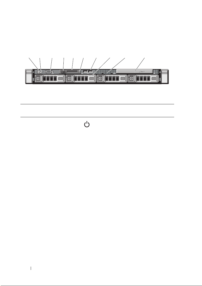
Front-Panel Features and Indicators
1 2
34
5
7
8
9
6
10
Figure 1-1. Front-Panel Features and Indicators
Item Indicator, Button, or
Connector
1Power-on indicator,
power button
Icon Description
The power-on indicator lights when the
system power is on.
The power button controls the
DC power supply output to the system.
When the optional system bezel is
installed, the power button is not
accessible.
NOTE: When powering on the system,
the video monitor can take from several
seconds to over 2 minutes to display an
image, depending on the amount of
memory installed in the system.
NOTE: On ACPI-compliant operating
systems, turning off the system using the
power button causes the system to
perform a graceful shutdown before
power to the system is turned off.
NOTE: To force an ungraceful shutdown,
press and hold the power button for
5 seconds.
10 About Your System

Item Indicator, Button, or
Connector
2 NMI button Used to troubleshoot software and
3 Video connector Connects a monitor to the system.
4 LCD menu buttons Allows you to navigate the control panel
5 LCD panel Provides system ID, status information,
Icon Description
device driver errors when using certain
operating systems. This button can be
pressed using the end of a paper clip.
Use this button only if directed to do so
by qualified support personnel or by the
operating system's documentation.
LCD menu.
and system error messages.
The LCD lights during normal system
operation. Both the systems management
software and the identification buttons
located on the front and back of the
system can cause the LCD to flash blue
to identify a particular system.
The LCD lights amber when the system
needs attention, and the LCD panel
displays an error code followed by
descriptive text.
NOTE: If the system is connected to
AC power and an error has been
detected, the LCD lights amber
regardless of whether the system
has been powered on.
6 System identification
button
The identification buttons on the front
and back panels can be used to locate
a particular system within a rack.
When one of these buttons is pushed,
the LCD panel on the front and the blue
system status indicator on the back blink
until one of the buttons is pushed again.
About Your System 11

Item Indicator, Button, or
Connector
7 USB connectors (2) Connect USB devices to the system. The
8 Hard drives (4) Up to four 3.5-inch hot-swappable hard
9 System identification
panel
10 Optical drive One slimline SATA DVD-ROM drive or
Icon Description
ports are USB 2.0-compliant.
drives.
A slide-out panel for system information
including the Express Service tag,
embedded NIC MAC address, and
iDRAC6 Enterprise card MAC address.
DVD+/-RW drive.
NOTE: DVD devices are data only.
LCD Panel Features
The system's LCD panel provides system information and status and error
messages to signify when the system is operating correctly or when the system
needs attention. See "LCD Status Messages" on page 21 for information on
specific status codes.
The LCD backlight lights blue during normal operating conditions and lights
amber to indicate an error condition. When the system is in standby mode,
the LCD backlight will switch off after five minutes of inactivity, and can be
turned on by pressing the Select button on the LCD panel. The LCD
backlight will remain off if LCD messaging is turned off through the BMC or
iDRAC utility, the LCD panel, or other tools.
12 About Your System
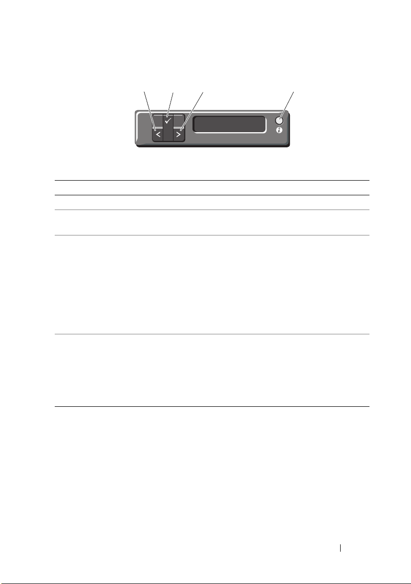
Figure 1-2. LCD Panel Features
1
2
4
3
Item Buttons Description
1 Left Moves the cursor back in one-step increments.
2 Select Selects the menu item highlighted by the
cursor.
3 Right Moves the cursor forward in one-step
increments.
During message scrolling:
• Press once to increase scrolling speed.
• Press again to stop.
• Press again to return to default scrolling.
• Press again to repeat the cycle.
4 System ID Turns the system ID mode on and off. (LCD
panel flashes blue) after "system ID mode on".
Press quickly to toggle the system ID on and
off. If the system hangs during POST, press and
hold the system ID button for more than
five seconds to enter BIOS Progress mode.
About Your System 13
Home Screen
The Home screen displays user-configurable information about the system.
This screen is displayed during normal system operation when there are no
status messages or errors present. When the system is in standby mode,
the LCD backlight will turn off after five minutes of inactivity if there are
no error messages. Press one of the three navigation buttons (Select, Left,
or Right) to view the Home screen.
To navigate to the Home screen from another menu, continue to select the
up arrow until the Home icon is displayed, and then select the
Home icon.
Setup Menu
Option Description
BMC or DRAC
NOTE: If an iDRAC6 Express
card is installed on the
system, the BMC option is
replaced by DRAC.
Set error Select SEL to display LCD error messages in a format
Set home Select the default information to be displayed on the
Select DHCP or Static IP to configure the network
mode. If Static IP is selected, the available fields are IP,
Subnet (Sub), and Gateway (Gtw). Select Setup DNS to
enable DNS and to view domain addresses. Two separate
DNS entries are available.
that matches the IPMI description in the SEL. This can
be useful when trying to match an LCD message with an
SEL entry.
Select Simple to display LCD error messages in a more
user-friendly description. See "LCD Status Messages" on
page 21 for a list of messages in this format.
LCD Home screen. See "View Menu" on page 15 to see
the options and option items that can be selected to
display by default on the Home screen.
14 About Your System

View Menu
Option Description
BMC IP or DRAC IP
NOTE: If an iDRAC6 Express
card is installed on the
system, the BMC IP option is
replaced by DRAC IP.
MAC Displays the MAC addresses for DRAC, iSCSIn, or NETn.
Name Displays the name of the Host, Model, or User String for
Number Displays the Asset tag or the Service tag for the system.
Power Displays the power output of the system in BTU/hr or
Temperature Displays the temperature of the system in Celsius or
Displays the IPv4 or IPv6 addresses for the optional
iDRAC6. Addresses include DNS (Primary and Secondary),
Gateway, IP, and Subnet (IPv6 does not have Subnet).
NOTE: BMC IP supports only IPv4 addresses.
NOTE: If the iDRAC6 Express card is not installed on the
system, the MAC option displays the MAC addresses for
BMC, iSCSIn, or NETn.
the system.
Watts. The display format can be configured in the "Set
home" submenu of the Setup menu (see "Setup Menu"
on page 14).
Fahrenheit. The display format can be configured in the
"Set home" submenu of the Setup menu (see "Setup
Menu" on page 14).
About Your System 15
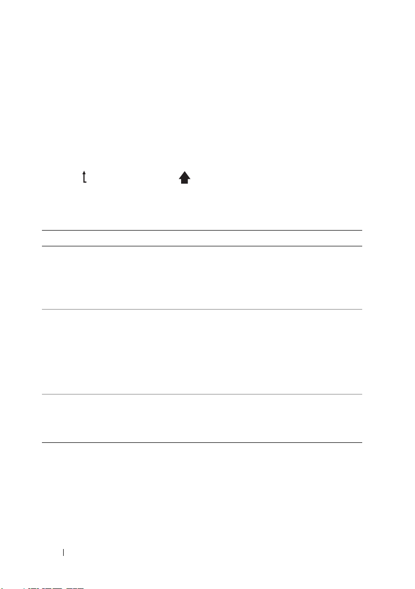
Hard Drive Status Indicators
1
2
Figure 1-3. Hard Drive Indicators
1 drive-activity indicator (green) 2 drive-status indicator (green and amber)
Drive-Status Indicator Pattern (RAID Only) Condition
Blinks green two times per second Identifying drive/preparing for removal
Off Drive ready for insertion or removal
NOTE: The drive status indicator remains
off until all hard drives are initialized after
system power is applied. Drives are not
ready for insertion or removal during this
time.
Blinks green, amber, and off Drive predicted failure
16 About Your System
Drive-Status Indicator Pattern (RAID Only) Condition
2
1
3
46
9
10
11
12
8
7
5
Blinks amber four times per second Drive failed
Blinks green slowly Drive rebuilding
Steady green Drive online
Blinks green 3 seconds, amber 3 seconds,
and off 6 seconds.
Rebuild aborted
Back-Panel Features and Indicators
Figure 1-4 shows the controls, indicators, and connectors located on the
system's back panel.
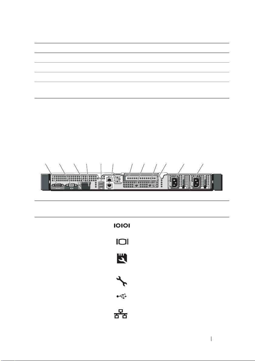
Figure 1-4. Back-Panel Features and Indicators
Item Indicator, Button, or
Connector
1 Serial connector Connects a serial device to the system.
2 Video connector Connects a VGA display to the system.
3 VFlash media slot
(optional)
4iDRAC6 Enterprise
port (optional)
5 USB connectors (2) Connect USB devices to the system.
6 Ethernet connectors
(2)
Icon Description
Connects an external SD memory card
for the optional iDRAC6 Enterprise
card.
Dedicated management port for the
optional iDRAC6 Enterprise card.
The ports are USB 2.0-compliant.
Embedded 10/100/1000 NIC
connectors.
About Your System 17

Item Indicator, Button, or
Connector
7 PCIe slot 1 PCI Express (generation 2) x16-wide
8Active ID CMA
connector
9System status
indicator light
10 System identification
button
11 Power supply 1 (PS1) 500 W power supply
12 Power supply 2 (PS2) 500 W power supply
Icon Description
expansion slot (full-height,
half-length).
Connector for attaching a system
indicator extension cable that is used
on a cable management arm.
Lights blue during normal
system operation.
Both the systems management software
and the identification buttons located
on the front and back of the system can
cause the indicator to flash blue to
identify a particular system.
Lights amber when the system needs
attention due to a problem.
Turns the system ID modes on and off.
The identification buttons on the front
and back panels can be used to locate a
particular system within a rack. When
one of these buttons is pushed, the
LCD panel on the front and the system
status indicator on the chassis back
panel light blue until one of the
buttons is pushed again.
18 About Your System
Guidelines for Connecting Optional External
1
2
Devices
• Turn off power to the system and external devices before attaching a new
external device. Turn on any external devices before turning on the system
(unless the documentation for the device specifies otherwise).
• Ensure that the appropriate driver for the attached device has been
installed on the system.
• If necessary to enable ports on your system, use the System Setup program.
S
ee "Using the System Setup Program and UEFI Boot Manager
page 55
.
" on
NIC Indicator Codes
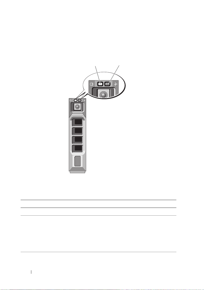
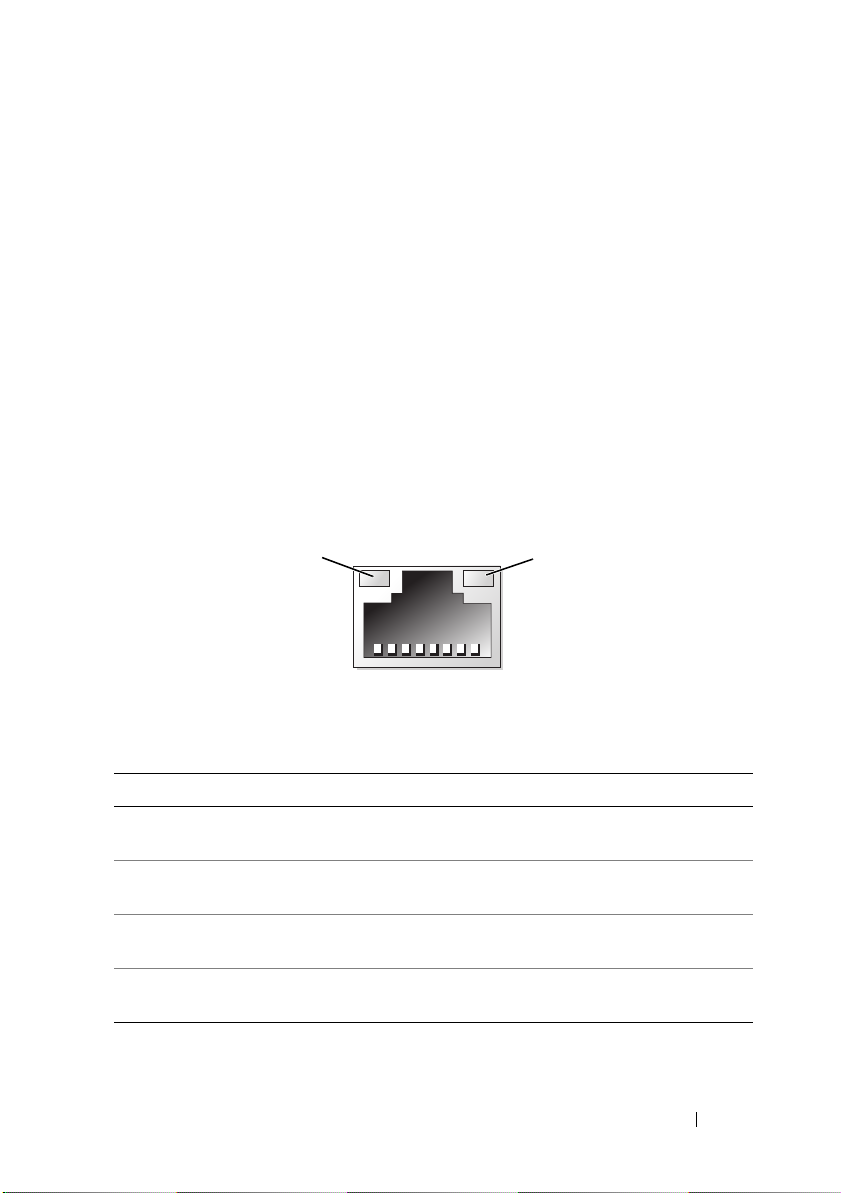
Figure 1-5. NIC Indicators
1 link indicator 2 activity indicator
Indicator Indicator Code
Link and activity
indicators are off
Link indicator is green The NIC is connected to a valid link partner on the
Link indicator is amber The NIC is connected to a valid network link at 10/100
Activity indicator is
amber blinking
The NIC is not connected to the network.
network.
Mbps.
Network data is being sent or received.
About Your System 19
Power Indicator Codes
1
An LED indicator on the power button indicates when power is supplied to
the system and the system is operational.
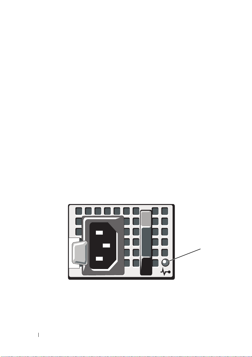
The power supplies have an indicator that shows whether power is present or
whether a power fault has occurred.
• Not lit—AC power is not connected.
• Green—In standby mode, indicates that a valid AC source is connected to
the power supply, and that the power supply is operational. When the
system is on, it also indicates that the power supply is providing DC power
to the system.
• Amber—Indicates a problem with the power supply.
• Alternating green and amber—When hot-adding a power supply, this
indicates that the power supply is mismatched with the other power
supply (a high output power supply and a Energy Smart power supply are
installed in the same system). Replace the power supply that has the
flashing indicator with a power supply that matches the capacity of the
other installed power supply.
Figure 1-6. Power Supply Status Indicator
1 power supply status
20 About Your System

LCD Status Messages
The system's control panel LCD provides status messages to signify when the
system is operating correctly or when the system needs attention.
The LCD lights blue to indicate a normal operating condition, and lights
amber to indicate an error condition. The LCD scrolls a message that
includes a status code followed by descriptive text. The table that follows
provides a listing of LCD status messages and the probable cause for each
message. The LCD messages refer to events recorded in the SEL. For
information on the SEL and configuring system management settings, see
the systems management software documentation.
NOTE: If your system fails to boot, press the System ID button for at least 5 seconds
until an error code appears on the LCD.Record the code, then see "Getting Help" on
page 169.
Table 1-1. LCD Status Messages
Code Text Causes Corrective Actions
N/A SYSTEM NAME A 62-character string that
can be defined by the user
in the System Setup
program.
The SYSTEM NAME is
displayed under the
following conditions:
• The system is
powered on.
•The power is off and
active errors are
displayed.
E1000 Failsafe
voltage error.
Contact
support.
Check the system event
log for critical failure
events.
This message is for
information only.
Yo u ca n c ha n g e t h e
system ID and name in
the System Setup
program. See "Using the
System Setup Program
and UEFI Boot Manager"
on page 55.
Remove AC power to the
system for 10 seconds and
restart the system.
If the problem persists,
see "Getting Help" on
page 169.
About Your System 21

Table 1-1. LCD Status Messages
Code Text Causes Corrective Actions
E1114 Ambient Temp
exceeds
allowed range.
E1116 Memory
disabled, temp
above range.
Power cycle
AC.
E1210 Motherboard
battery
failure. Check
battery.
E1211 RAID
Controller
battery
failure. Check
battery.
E1216 3.3V Regulator
failure.
Reseat PCIe
cards.
E1229 CPU # VCORE
Regulator
failure.
Reseat CPU.
(continued)
Ambient temperature has
a reached a point outside
of the allowed range.
Memory has exceeded
allowable temperature and
has been disabled to
prevent damage to the
components.
CMOS battery is missing
or the voltage is outside of
the allowable range.
RAID battery is either
missing, bad, or unable to
recharge due to thermal
issues.
3.3 V voltage regulator has
failed.
Specified processor
VCORE voltage regulator
has failed.
See "Troubleshooting
System Cooling
Problems" on page 147.
Remove AC power to the
system for 10 seconds and
restart the system.
See "Troubleshooting
System Cooling
Problems" on page 147.
If the problem persists,
see "Getting Help" on
page 169.
See "Troubleshooting the
System Battery" on
page 146.
Reseat the RAID battery
connector. See
"Troubleshooting System
Cooling Problems" on
page 147.
Remove and reseat the
PCIe expansion cards.
If the problem persists,
see "Troubleshooting
Expansion Cards" on
page 155.
Reseat the processor(s).
See "Troubleshooting the
Processors" on page 156.
If the problem persists,
see "Getting Help" on
page 169.
22 About Your System

Table 1-1. LCD Status Messages
Code Text Causes Corrective Actions
E122A CPU # VTT
Regulator
failure.
Reseat CPU.
E122C CPU Power
Fault. Power
cycle AC.
E122D Memory
Regulator #
Failed. Reseat
DIMMs.
E122E On-board
regulator
failed. Call
support.
E1310 Fan ## RPM
exceeding
range. Check
fan.
E1311 Fan module ##
RPM exceeding
range. Check
fan.
E1313 Fan redundancy
lost. Check
fans.
(continued)
Specified processor VTT
voltage regulator has
failed.
A power fault was
detected when powering
up the processor(s).
One of the memory
regulators has failed.
One of the on-board
voltage regulators has
failed.
RPM of specified fan is
outside of the intended
operating range.
RPM of specified fan in
specified module is
outside of intended
operating range.
The system is no longer
fan redundant. Another
fan failure would put the
system at risk of
over-heating.
Reseat the processor(s).
See "Troubleshooting the
Processors" on page 156.
If the problem persists,
see "Getting Help" on
page 169.
Remove AC power to the
system for 10 seconds and
restart the system.
If the problem persists,
see "Getting Help" on
page 169.
Reseat the memory
modules. See
"Troubleshooting System
Memory" on page 148.
Remove AC power to the
system for 10 seconds and
restart the system.
If the problem persists,
see "Getting Help" on
page 169.
See "Troubleshooting
System Cooling
Problems" on page 147.
See "Troubleshooting
System Cooling
Problems" on page 147.
Check LCD for
additional scrolling
messages. See
"Troubleshooting a Fan"
on page 148.
About Your System 23

Table 1-1. LCD Status Messages
Code Text Causes Corrective Actions
E1410 Internal Error
detected.
Check "FRU X".
E1414 CPU # temp
exceeding
range. Check
CPU heatsink.
E1418 CPU # not
detected.
Check CPU is
seated
properly.
E141C Unsupported
CPU
configuration.
Check CPU or
BIOS revision.
E141F CPU # protocol
error. Power
cycle AC.
(continued)
Specified processor has an
internal error. The error
may or may not have been
caused by the processor.
Specified processor is out
of acceptable temperature
range.
Specified processor is
missing or bad, and the
system is in an
unsupported
configuration.
Processors are in an
unsupported
configuration.
The system BIOS
has reported a processor
protocol error.
Remove AC power to the
system for 10 seconds and
restart the system.
If the problem persists,
see "Getting Help" on
page 169.
Ensure that the processor
heat sinks are properly
installed. See
"Troubleshooting the
Processors" on page 156
and "Troubleshooting
System Cooling
Problems" on page 147.
Ensure that the specified
microprocessor is
properly installed. See
"Troubleshooting the
Processors" on page 156.
Ensure that your
processors match and
conform to the type
described in the processor
technical specifications
outlined in your system’s
Getting Started Guide.
Remove AC power to the
system for 10 seconds and
restart the system.
If the problem persists,
see "Getting Help" on
page 169.
24 About Your System

Table 1-1. LCD Status Messages
Code Text Causes Corrective Actions
E1420 CPU Bus parity
error. Power
cycle AC.
E1422 CPU # machine
check error.
Power
cycle AC.
E1610 Power Supply #
(### W)
missing.
Check power
supply.
E1614 Power Supply #
(### W) error.
Check power
supply.
E1618 Predictive
failure on
Power Supply #
(### W).
Check PSU.
E161C Power Supply #
(### W) lost
AC power.
Check PSU
cables.
(continued)
The system BIOS has
reported a processor bus
parity error.
The system BIOS has
reported a machine
check error.
Specified power supply
was removed or is missing
from the system.
Specified power supply
has failed.
An over-temperature
condition or power supply
communication error has
caused the predictive
warning of an impending
power supply failure.
Specified power supply is
attached to the system,
but it has lost its
AC input.
Remove AC power to the
system for 10 seconds and
restart the system.
If the problem persists,
see "Getting Help" on
page 169.
Remove AC power to the
system for 10 seconds and
restart the system.
If the problem persists,
see "Getting Help" on
page 169.
See "Troubleshooting
Power Supplies" on
page 147.
See "Troubleshooting
Power Supplies" on
page 147.
See "Troubleshooting
Power Supplies" on
page 147.
Check the AC power
source for the specified
power supply. If the
problem persists, see
"Troubleshooting Power
Supplies" on page 147.
About Your System 25

Table 1-1. LCD Status Messages
Code Text Causes Corrective Actions
E1620 Power Supply #
(### W) AC
power error.
Check PSU
cables.
E1624 Lost power
supply
redundancy.
Check PSU
cables.
E1626 Power Supply
Mismatch. PSU1
= ### W, PSU2
= ### W.
E1629 Power required
> PSU wattage.
Check PSU and
config.
E1710 I/O channel
check error.
Review & clear
SEL.
(continued)
Specified power supply's
AC input is outside of the
allowable range.
The power supply
subsystem is no longer
redundant. If the
remaining power supply
fails, the system will
shut down.
The power supplies in
the system are not the
same wattage.
The system configuration
requires more power than
the power supplies can
provide, even with
throttling.
The system BIOS has
reported an I/O channel
check.
Check the AC power
source for the specified
power supply. If the
problem persists,
see "Troubleshooting
Power S upplies" on
page 147.
See "Troubleshooting
Power S upplies" on
page 147.
Ensure that power
supplies with matching
wattage are installed.
See the Technical
Specifications outlined in
your system’s Getting
Started Guide.
Turn off power to the
system, reduce the
hardware configuration or
install higher-wattage
power supplies, and then
restart the system.
Check the SEL for more
information and then
clear the SEL. Remove
AC power to the system
for 10 seconds and restart
the system.
If the problem persists,
see "Getting Help" on
page 169.
26 About Your System

Table 1-1. LCD Status Messages
Code Text Causes Corrective Actions
E1711 PCI parity
error on Bus
## Device ##
Function ##
PCI parity
error on Slot
#. Review &
clear SEL.
E1712 PCI system
error on Bus
## Device ##
Function ##
E1714 Unknown error.
Review & clear
SEL.
E171F PCIe fatal
error on Bus
## Device ##
Function ##
(continued)
The system BIOS has
reported a PCI parity
error on a component
that resides in PCI
configuration space at
bus ##, device ##,
function ##.
The system BIOS has
reported a PCI parity
error on a component
that resides in the
specified slot.
The system BIOS has
reported a PCI system
error on a component
that resides in PCI
configuration space at
bus ##, device ##,
function ##.
The system BIOS has
determined there has
been an error in the
system, but is unable to
determine its origin.
The system BIOS has
reported a PCIe fatal
error on a component
that resides in PCI
configuration space at
bus ##, device ##,
function ##.
Remove and reseat the
PCIe expansion cards.
If the problem persists,
see "Troubleshooting
Expansion Cards" on
page 155.
Remove and reseat the
PCIe expansion cards.
If the problem persists,
see "Troubleshooting
Expansion Cards" on
page 155.
Remove and reseat the
PCIe expansion cards.
If the problem persists,
see "Troubleshooting
Expansion Cards" on
page 155.
Check the SEL for more
information and then
clear the SEL. Remove
AC power to the system
for 10 seconds and restart
the system.
If the problem persists,
see "Getting Help" on
page 169.
Remove and reseat the
PCIe expansion cards.
If the problem persists,
see "Troubleshooting
Expansion Cards" on
page 155.
About Your System 27

Table 1-1. LCD Status Messages
Code Text Causes Corrective Actions
E1810 Hard drive ##
fault. Review
& clear SEL.
E1812 Hard drive ##
removed. Check
drive.
E1920 iDRAC6 Upgrade
Failed.
E1A14 SAS cable A
failure. Check
connection.
E1A15 SAS cable B
failure. Check
connection.
E1A1D Control panel
USB cable not
detected.
Check cable.
E2010 Memory not
detected.
Inspect DIMMs.
(continued)
The specified hard drive
has experienced a fault.
The specified hard
drive has been removed
from the system.
Optional iDRAC6
upgrade has failed.
SAS cable A is missing
or bad.
SAS cable B is missing
or bad.
USB cable to the control
panel is missing or bad.
No memory was detected
in the system.
See "Troubleshooting a
Hard Drive" on page 152.
Information only.
See "Troubleshooting
Expansion Cards" on
page 155.
Reseat the cable. If the
problem persists,
replace cable.
If the problem persists,
see "Getting Help" on
page 169.
Reseat the cable. If the
problem persists,
replace cable.
If the problem persists,
see "Getting Help" on
page 169.
Reseat the cable. If the
problem persists, replace
cable.
If the problem persists,
see "Getting Help" on
page 169.
Install memory or reseat
memory modules. See
"Installing Memory
Modules" on page 115 or
"Troubleshooting System
Memory" on page 148.
28 About Your System

Table 1-1. LCD Status Messages
Code Text Causes Corrective Actions
E2011 Memory
configuration
failure.
Check DIMMs.
E2012 Memory
configured but
unusable.
Check DIMMs.
E2013 BIOS unable to
shadow memory.
Check DIMMs.
E2014 CMOS RAM
failure. Power
cycle AC.
E2015 DMA Controller
failure. Power
cycle AC.
E2016 Interrupt
Controller
failure. Power
cycle AC.
E2017 Timer refresh
failure. Power
cycle AC.
(continued)
Memory detected, but is
not configurable.
Error detected during
memory configuration.
Memory configured, but is
unusable.
The system BIOS failed to
copy its flash image into
memory.
CMOS failure. CMOS
RAM not functioning
properly.
DMA controller failure. Remove AC power to the
Interrupt controller
failure.
Timer refresh failure. Remove AC power to the
See "Troubleshooting
System Memory" on
page 148.
See "Troubleshooting
System Memory" on
page 148.
See "Troubleshooting
System Memory" on
page 148.
Remove AC power to the
system for 10 seconds and
restart the system.
If the problem persists,
see "Getting Help" on
page 169.
system for 10 seconds and
restart the system.
If the problem persists,
see "Getting Help" on
page 169.
Remove AC power to the
system for 10 seconds and
restart the system.
If the problem persists,
see "Getting Help" on
page 169.
system for 10 seconds and
restart the system.
If the problem persists,
see "Getting Help" on
page 169.
About Your System 29

Table 1-1. LCD Status Messages
Code Text Causes Corrective Actions
E2018 Programmable
Timer error.
Power cycle
AC.
E2019 Parity error.
Power cycle
AC.
E201A SuperIO
failure. Power
cycle AC.
E201B Keyboard
Controller
error. Power
cycle AC.
E201C SMI
initialization
failure. Power
cycle AC.
(continued)
Programmable interval
timer error.
Parity error. Remove AC power to the
SIO failure. Remove AC power to the
Keyboard controller
failure.
System management
interrupt (SMI)
initialization failure.
Remove AC power to the
system for 10 seconds and
restart the system.
If the problem persists,
see "Getting Help" on
page 169.
system for 10 seconds and
restart the system.
If the problem persists,
see "Getting Help" on
page 169.
system for 10 seconds and
restart the system.
If the problem persists,
see "Getting Help" on
page 169.
Remove AC power to the
system for 10 seconds and
restart the system.If the
problem persists,
see "Getting Help" on
page 169.
Remove AC power to the
system for 10 seconds and
restart the system.
If the problem persists,
see "Getting Help" on
page 169.
30 About Your System
 Loading...