

Page 1

Dell Remote Access Controller 5
Firmware Version 1.30
User’s Guide
Page 2

Notes and Notices
NOTE: A NOTE indicates important information that helps you make better use of
your computer.
NOTICE: A NOTICE indicates either potential damage to hardware or loss of data
and tells you how to avoid the problem.
____________________
Information in this document is subject to change without notice.
© 2007 Dell Inc. All rights reserved.
Reproduction in any manner whatsoever without the written permission of Dell Inc. is strictly forbidden.
Trademarks used in this text: Dell, the DELL logo, Dell OpenManage, and PowerEdge, are trademarks
of Dell Inc.; Microsoft, Active Directory, Internet Explorer, Windows, Windows NT, and Windows Server
are registered trademarks and Windows Vista is a trademark of Microsoft Corporation; Red Hat is a
registered trademark of Red Hat, Inc.; Novell and SUSE are registered trademarks of Novell Corporation.
Intel is a registered trademark of Intel Corporation; UNIX is a registered trademark of The Open Group
in the United States and other countries.
Copyright 1998-2006 The OpenLDAP Foundation. All rights reserved. Redistribution and use in
source and binary forms, with or without modification, are permitted only as authorized by the
OpenLDAP Public License. A copy of this license is available in the file LICENSE in the top-level
directory of the distribution or, alternatively, at http://www.OpenLDAP.org/license.html.
OpenLDAP is a registered trademark of the OpenLDAP Foundation. Individual files and/or
contributed packages may be copyrighted by other parties and subject to additional restrictions. This
work is derived from the University of Michigan LDAP v3.3 distribution. This work also contains
materials derived from public sources. Information about OpenLDAP can be obtained at http://
www.openldap.org/. Portions Copyright 1998-2004 Kurt D. Zeilenga. Portions Copyright 1998-2004
Net Boolean Incorporated. Portions Copyright 2001-2004 IBM Corporation. All rights reserved.
Redistribution and use in source and binary forms, with or without modification, are permitted only
as authorized by the OpenLDAP Public License. Portions Copyright 1999-2003 Howard Y.H. Chu.
Portions Copyright 1999-2003 Symas Corporation. Portions Copyright 1998-2003 Hallvard B.
Furuseth. All rights reserved. Redistribution and use in source and binary forms, with or without
modification, are permitted provided that this notice is preserved. The names of the copyright holders
may not be used to endorse or promote products derived from this software without their specific prior
written permission. This software is provided "as is'' without express or implied warranty. Portions
Copyright (c) 1992-1996 Regents of the University of Michigan. All rights reserved. Redistribution
and use in source and binary forms are permitted provided that this notice is preserved and that due
credit is given to the University of Michigan at Ann Arbor. The name of the University may not be used
to endorse or promote products derived from this software without specific prior written permission.
This software is provided "as is'' without express or implied warranty. Other trademarks and trade
names may be used in this document to refer to either the entities claiming the marks and names or their
products. Dell Inc. disclaims any proprietary interest in trademarks and trade names other than its own.
Other trademarks and trade names may be used in this document to refer to either the entities claiming
the marks and names or their products. Dell Inc. disclaims any proprietary interest in trademarks and
trade names other than its own.
September 2007 Rev. A00
Page 3

Contents
1 DRAC 5 Overview . . . . . . . . . . . . . . . . . . 21
What’s New in DRAC 5 in this Release? . . . . . . . . 21
DRAC 5 Hardware Features
. . . . . . . . . . . . . . . 22
Hardware Specifications . . . . . . . . . . . . . . . . 22
Power Specifications
. . . . . . . . . . . . . . . 22
Connectors . . . . . . . . . . . . . . . . . . . . . 23
DRAC 5 Ports
Supported Remote Access Connections
. . . . . . . . . . . . . . . . . . . . 23
. . . . . . . . 24
DRAC 5 Security Features . . . . . . . . . . . . . . . . 25
Supported Platforms
Supported Operating Systems
Supported Web Browsers
. . . . . . . . . . . . . . . . . . 26
. . . . . . . . . . . . . . 27
. . . . . . . . . . . . . . . . 29
Disabling the Whitelist Feature in
Mozilla Firefox
Features
. . . . . . . . . . . . . . . . . . . . . . . . . 31
. . . . . . . . . . . . . . . . . . . 30
Other Documents You May Need . . . . . . . . . . . . 32
Contents 3
Page 4

2 Installing and Setting Up the
DRAC 5 . . . . . . . . . . . . . . . . . . . . . . . . . . . 35
Before You Begin . . . . . . . . . . . . . . . . . . . . 35
Installing the DRAC 5 Hardware
Configuring Your System to Use a DRAC 5
. . . . . . . . . . . . 35
. . . . . . . 36
Software Installation and Configuration Overview . . . 37
Installing Your DRAC 5 Software
. . . . . . . . . . 37
Configuring Your DRAC 5 . . . . . . . . . . . . . . 38
Installing the Software on the Managed System . . . . 38
Configuring the Managed System to
Capture the Last Crash Screen
. . . . . . . . . . . 39
Disabling the Windows
Automatic Reboot Option
. . . . . . . . . . . . . . 39
Installing the Software on the
Management Station
. . . . . . . . . . . . . . . . . . 40
Configuring Your
Red Hat Enterprise Linux (Version 4)
Management Station
. . . . . . . . . . . . . . . . 41
Installing and Removing RACADM on a
Linux Management Station . . . . . . . . . . . . . 41
Installing RACADM
Configuring a Supported Web Browser
. . . . . . . . . . . . . . . . . 41
. . . . . . . . . 42
Configuring Your Web Browser to
Connect to the Web-Based Interface
. . . . . . . 42
List of Trusted Domains . . . . . . . . . . . . . . 43
32-bit and 64-bit Web Browsers
. . . . . . . . . . 43
Viewing Localized Versions of the
Web-Based Interface . . . . . . . . . . . . . . . 43
4 Contents
Configuring DRAC 5 Properties
. . . . . . . . . . . . . 45
Page 5

Configuring the DRAC 5 Network Settings . . . . . . . 45
Adding and Configuring DRAC 5 Users
Updating the DRAC 5 Firmware
Before You Begin
. . . . . . . . . . . . . . . . . . 46
Downloading the DRAC 5 Firmware
. . . . . . . . . 46
. . . . . . . . . . . . . 46
. . . . . . . . 47
Updating the DRAC 5 Firmware Using the
Web-Based Interface . . . . . . . . . . . . . . . 47
Clearing the Browser Cache
Accessing the DRAC 5 Through a Network
. . . . . . . . . . . . 48
. . . . . . . 48
Configuring IPMI . . . . . . . . . . . . . . . . . . . . 50
Configuring IPMI Using the
Web-Based Interface
Configuring IPMI Using the RACADM CLI
Configuring Platform Events
Configuring Platform Event Filters (PEF)
Configuring PET
. . . . . . . . . . . . . . . 51
. . . . . 53
. . . . . . . . . . . . . . 57
. . . . . . 58
. . . . . . . . . . . . . . . . . . 60
Configuring E-Mail Alerts . . . . . . . . . . . . . 62
3 Configuring and Using the
DRAC 5 Command Line Console . . . . . . . 65
Command Line Console Features . . . . . . . . . . . . 65
Enabling and Configuring the Managed System to
Use a Serial or Telnet Console
Using the connect com2 Serial Command
. . . . . . . . . . . . . 66
. . . . . 66
Configuring the BIOS Setup Program for a
Serial Connection on the Managed System
Using the Remote Access Serial Interface
. . . . 66
. . . . 67
Configuring Linux for Serial Console
Redirection During Boot
. . . . . . . . . . . . . . 68
Contents 5
Page 6

Enabling Login to the Console After Boot . . . . . 70
Enabling the
DRAC 5 Serial/Telnet/SSH Console . . . . . . . . . 73
Using the RACADM Command to Configure the
Settings for the Serial and Telnet Console . . . . . 74
Using the Secure Shell (SSH) . . . . . . . . . . . . . . 76
Enabling Additional DRAC 5 Security Options
. . . . . 77
Connecting to the Managed System Through the
Local Serial Port or
Telnet Management Station (Client System)
. . . . . . 83
Connecting the DB-9 Cable for the Serial Console
Configuring the Management Station
Terminal Emulation Software
. . . . . . . . . . . . . . 85
Configuring Linux Minicom for
Serial Console Emulation
. . . . . . . . . . . . . . 85
Configuring HyperTerminal for
Serial Console Redirection . . . . . . . . . . . . . 87
Configuring Linux XTerm for
Telnet Console Redirection . . . . . . . . . . . . . 88
Enabling Microsoft Telnet for
Telnet Console Redirection . . . . . . . . . . . . . 88
Using a Serial or Telnet Console . . . . . . . . . . . . 90
4 Configuring the DRAC 5 Using the
Web User Interface . . . . . . . . . . . . . . . . . 91
. . . 84
6 Contents
Accessing the Web-Based Interface . . . . . . . . . . 91
Logging In
Logging Out
. . . . . . . . . . . . . . . . . . . . . 92
. . . . . . . . . . . . . . . . . . . . . 93
Page 7

Configuring the DRAC 5 NIC . . . . . . . . . . . . . . . 93
Configuring the Network and
IPMI LAN Settings
Configuring the Network Security Settings
. . . . . . . . . . . . . . . . . 93
. . . . 96
Adding and Configuring DRAC 5 Users
. . . . . . . . . 98
Configuring and Managing
Active Directory Certificates
(Standard Schema and Extended Schema)
. . . . . . . 102
Configuring Active Directory
(Standard Schema and Extended Schema)
. . . . 103
Uploading an Active Directory CA Certificate . . . 106
Downloading a DRAC Server Certificate
. . . . . 107
Viewing an Active Directory CA Certificate
Securing DRAC 5 Communications
Using SSL and Digital Certificates
Secure Sockets Layer (SSL)
. . . . . . . . . . . 108
. . . . . . . . . . . . 108
Certificate Signing Request (CSR) . . . . . . . . . 109
Accessing the SSL Main Menu
. . . . . . . . . . 109
Generating a New Certificate
Signing Request . . . . . . . . . . . . . . . . . . 110
Uploading a Server Certificate
. . . . . . . . . . . 112
Viewing a Server Certificate . . . . . . . . . . . . 112
Configuring Serial and Terminal Modes
Configuring IPMI and RAC Serial
. . . . . . . . 113
. . . . . . . . . 113
Configuring Terminal Mode . . . . . . . . . . . . 115
. . . . 107
Configuring Serial Over LAN . . . . . . . . . . . . . . 116
Configuring Services
Configuring Smart Card
Frequently Asked Questions
. . . . . . . . . . . . . . . . . . 118
. . . . . . . . . . . . . . . . . 122
. . . . . . . . . . . . . . 123
Contents 7
Page 8

5 Recovering and Troubleshooting the
Managed System . . . . . . . . . . . . . . . . . . 127
First Steps to Troubleshoot a Remote System . . . . . . 127
Managing Power on a Remote System
Selecting Power Control Actions
Viewing System Information
Main System Chassis
. . . . . . . . . . . . . . 129
. . . . . . . . . . . . . . . . 129
Remote Access Controller
Using the System Event Log (SEL)
. . . . . . . . . 128
. . . . . . . . . 128
. . . . . . . . . . . . . 130
. . . . . . . . . . . . 130
Viewing the Last System Crash Screen . . . . . . . . . 132
Using the RAC Log
Using the Diagnostic Console
. . . . . . . . . . . . . . . . . . . . 133
. . . . . . . . . . . . . . 134
Troubleshooting Network Problems . . . . . . . . . . 135
Troubleshooting Alerting Problems
. . . . . . . . . . . 136
6 Using the DRAC 5 With
Microsoft Active Directory . . . . . . . . . . 137
Advantages and Disadvantages of
Extended Schema and Standard Schema
. . . . . . . . 137
8 Contents
Extended Schema Active Directory Overview . . . . . 138
Active Directory Schema Extensions
. . . . . . . 138
Overview of the RAC Schema Extensions . . . . . 139
Active Directory Object Overview
. . . . . . . . . 139
Configuring Extended Schema
Active Directory to Access Your DRAC 5 . . . . . 143
Extending the Active Directory Schema
. . . . . . 143
Page 9

Installing the Dell Extension to the
Active Directory Users and
Computers Snap-In
. . . . . . . . . . . . . . . . . 149
Adding DRAC 5 Users and Privileges to
Active Directory . . . . . . . . . . . . . . . . . . 150
Configuring the DRAC 5 With Extended Schema
Active Directory and Web-Based Interface
. . . . 152
Configuring the DRAC 5 With Extended Schema
Active Directory and RACADM . . . . . . . . . . 154
Standard Schema Active Directory Overview
. . . . . 156
Configuring Standard Schema
Active Directory to Access Your DRAC 5
. . . . . 158
Configuring the DRAC 5 With Standard Schema
Active Directory and
Web-Based Interface . . . . . . . . . . . . . . . 159
Configuring the DRAC 5 With Standard Schema
Active Directory and
RACADM . . . . . . . . . . . . . . . . . . . . . . 161
Enabling SSL on a Domain Controller
. . . . . . . . . 162
Exporting the Domain Controller
Root CA Certificate
. . . . . . . . . . . . . . . . . 162
Importing the DRAC 5 Firmware
SSL Certificate . . . . . . . . . . . . . . . . . . . 164
Using Active Directory to Log In To the DRAC 5
Frequently Asked Questions
. . . . . . . . . . . . . . 165
. . . . 164
7 Using GUI Console Redirection . . . . . . . 169
Overview . . . . . . . . . . . . . . . . . . . . . . . . 169
Contents 9
Page 10

Using Console Redirection . . . . . . . . . . . . . . . 169
Supported Screen Resolutions
Refresh Rates on the Managed System
Configuring Your Management Station
Configuring Console Redirection
. . . . . . 170
. . . . . . 170
. . . . . . . . . . 170
Opening a Console Redirection Session . . . . . . 172
Disabling or Enabling Local Video
. . . . . . . . . 173
Using the Video Viewer
Accessing the Viewer Menu Bar
Adjusting the Video Quality
Synchronizing the Mouse Pointers
Frequently Asked Questions
. . . . . . . . . . . . . . . . . 174
. . . . . . . . . 175
. . . . . . . . . . . . . 178
. . . . . . . . 178
. . . . . . . . . . . . . . 179
8 Using and Configuring
Virtual Media . . . . . . . . . . . . . . . . . . . . . 187
Overview . . . . . . . . . . . . . . . . . . . . . . . . . 187
Installing the Virtual Media Plug-In
Windows-Based Management Station
Linux-Based Management Station
Running Virtual Media
. . . . . . . . . . . . . . . . . . 190
Supported Virtual Media Configurations
Running Virtual Media Using the
Web User Interface . . . . . . . . . . . . . . . . 190
Attaching and Detaching the
Virtual Media Feature
. . . . . . . . . . . . . . . 192
Booting From Virtual Media . . . . . . . . . . . . 193
Installing Operating Systems Using
Virtual Media
. . . . . . . . . . . . . . . . . . . . 194
Using Virtual Media When the Server’s
Operating System Is Running
. . . . . . . . . . 189
. . . . . . 189
. . . . . . . . . 189
. . . . . . 190
. . . . . . . . . . . . 194
10 Contents
Page 11

Using Virtual Flash . . . . . . . . . . . . . . . . . . . 195
Enabling Virtual Flash
. . . . . . . . . . . . . . . 195
Disabling Virtual Flash . . . . . . . . . . . . . . . 196
Storing Images in a Virtual Flash
Configuring a Bootable Virtual Flash
. . . . . . . . . . 196
. . . . . . . . 196
Using the Virtual Media
Command Line Interface Utility
Utility Installation
. . . . . . . . . . . . . . . . . . 198
. . . . . . . . . . . . . 197
Command Line Options . . . . . . . . . . . . . . . 198
VM-CLI Parameters
VM-CLI Operating System Shell Options
. . . . . . . . . . . . . . . . 199
. . . . . 202
Frequently Asked Questions
. . . . . . . . . . . . . . 203
9 Using the RACADM
Command Line Interface . . . . . . . . . . . . 209
Using a Serial or Telnet Console . . . . . . . . . . . . 209
Logging in to the DRAC 5
Starting a Text Console . . . . . . . . . . . . . . . 210
Using RACADM . . . . . . . . . . . . . . . . . . . . . 210
Using RACADM Remotely
RACADM Synopsis
RACADM Options
Enabling and Disabling the racadm
Remote Capability . . . . . . . . . . . . . . . . . 213
RACADM Subcommands
RACADM Error Messages
Configuring Multiple DRAC 5 Cards
Creating a DRAC 5 Configuration File
Parsing Rules
. . . . . . . . . . . . . . . . . . . . 218
Modifying the DRAC 5 IP Address
. . . . . . . . . . . . . . 209
. . . . . . . . . . . . . 211
. . . . . . . . . . . . . . . . . 212
. . . . . . . . . . . . . . . . . 212
. . . . . . . . . . . . . 213
. . . . . . . . . . . . . 215
. . . . . . . . . . 215
. . . . . . . 216
. . . . . . . . . 220
Contents 11
Page 12

Using the RACADM Utility to
Configure the DRAC 5
Before You Begin
Adding a DRAC 5 User
Removing a DRAC 5 User
. . . . . . . . . . . . . . . . . . 221
. . . . . . . . . . . . . . . . . . 221
. . . . . . . . . . . . . . . 222
. . . . . . . . . . . . . . 223
Testing e-mail Alerting . . . . . . . . . . . . . . . 223
Testing the RAC SNMP Trap Alert Feature
. . . . . 223
Enabling a DRAC 5 User With Permissions
Configuring DRAC 5 Network Properties . . . . . . 224
Frequently Asked Questions . . . . . . . . . . . . . . 226
10 Deploying Your Operating System
Using VM-CLI . . . . . . . . . . . . . . . . . . . . 227
Before You Begin . . . . . . . . . . . . . . . . . . . . 227
Remote System Requirements
Network Requirements . . . . . . . . . . . . . . . 228
. . . . . . . . . . . 227
. . . . 224
11 Using the DRAC 5 SM-CLP
Command Line Interface . . . . . . . . . . . . 231
12 Contents
Creating a Bootable Image File
Creating an Image File for Linux Systems
Creating an Image File for Windows Systems
Preparing for Deployment
Configuring the Remote Systems
. . . . . . . . . . . . . 228
. . . . . 228
. . . 228
. . . . . . . . . . . . . . . . 229
. . . . . . . . . . 229
Deploying the Operating System . . . . . . . . . . . . 229
DRAC 5 SM-CLP Support . . . . . . . . . . . . . . . . 231
Page 13

SM-CLP Features . . . . . . . . . . . . . . . . . . . . 231
SM-CLP Management Operations and
Targets
Options
DRAC 5 SM-CLP Examples
. . . . . . . . . . . . . . . . . . . . . . . 232
. . . . . . . . . . . . . . . . . . . . . . . 233
. . . . . . . . . . . . . 233
12 Troubleshooting . . . . . . . . . . . . . . . . . . 243
Troubleshooting the DRAC 5 . . . . . . . . . . . . . . 243
A RACADM Subcommand Overview . . . . . 245
help . . . . . . . . . . . . . . . . . . . . . . . . . . . 245
arp . . . . . . . . . . . . . . . . . . . . . . . . . . . . 246
clearasrscreen
. . . . . . . . . . . . . . . . . . . . . . . . . . 247
config
getconfig
. . . . . . . . . . . . . . . . . . . . . 246
. . . . . . . . . . . . . . . . . . . . . . . . . 249
coredump . . . . . . . . . . . . . . . . . . . . . . . . 251
coredumpdelete
fwupdate
. . . . . . . . . . . . . . . . . . . . . 252
. . . . . . . . . . . . . . . . . . . . . . . . . 253
getssninfo . . . . . . . . . . . . . . . . . . . . . . . . 256
getsysinfo
getractime
ifconfig
netstat
. . . . . . . . . . . . . . . . . . . . . . . . 258
. . . . . . . . . . . . . . . . . . . . . . . . 261
. . . . . . . . . . . . . . . . . . . . . . . . . . 262
. . . . . . . . . . . . . . . . . . . . . . . . . . 262
Contents 13
Page 14

ping . . . . . . . . . . . . . . . . . . . . . . . . . . . 263
setniccfg
getniccfg
. . . . . . . . . . . . . . . . . . . . . . . . . 263
. . . . . . . . . . . . . . . . . . . . . . . . . 265
getsvctag . . . . . . . . . . . . . . . . . . . . . . . . . 266
racdump
racreset
. . . . . . . . . . . . . . . . . . . . . . . . . 267
. . . . . . . . . . . . . . . . . . . . . . . . . 268
racresetcfg . . . . . . . . . . . . . . . . . . . . . . . . 269
serveraction
getraclog
. . . . . . . . . . . . . . . . . . . . . . . 270
. . . . . . . . . . . . . . . . . . . . . . . . . 271
clrraclog . . . . . . . . . . . . . . . . . . . . . . . . . 273
. . . . . . . . . . . . . . . . . . . . . . . . . . 273
getsel
. . . . . . . . . . . . . . . . . . . . . . . . . . . 274
clrsel
gettracelog
. . . . . . . . . . . . . . . . . . . . . . . . 275
sslcsrgen . . . . . . . . . . . . . . . . . . . . . . . . . 276
sslcertupload
. . . . . . . . . . . . . . . . . . . . . . 278
14 Contents
sslcertdownload
. . . . . . . . . . . . . . . . . . . . . 279
sslcertview . . . . . . . . . . . . . . . . . . . . . . . 281
sslkeyupload
testemail
testtrap
vmdisconnect
. . . . . . . . . . . . . . . . . . . . . . . 283
. . . . . . . . . . . . . . . . . . . . . . . . . 284
. . . . . . . . . . . . . . . . . . . . . . . . . . 285
. . . . . . . . . . . . . . . . . . . . . . 287
Page 15

vmkey . . . . . . . . . . . . . . . . . . . . . . . . . . 288
usercertupload
usercertview
. . . . . . . . . . . . . . . . . . . . . 288
. . . . . . . . . . . . . . . . . . . . . . 290
localConRedirDisable . . . . . . . . . . . . . . . . . . 291
B DRAC 5 Property Database Group and
Object Definitions . . . . . . . . . . . . . . . . . 293
Displayable Characters . . . . . . . . . . . . . . . . . 293
idRacInfo
cfgLanNetworking
. . . . . . . . . . . . . . . . . . . . . . . . 293
idRacProductInfo (Read Only)
idRacDescriptionInfo (Read Only)
. . . . . . . . . . . 293
. . . . . . . . . 294
idRacVersionInfo (Read Only) . . . . . . . . . . . 294
idRacBuildInfo (Read Only)
idRacName (Read Only)
. . . . . . . . . . . . 294
. . . . . . . . . . . . . . 295
idRacType (Read Only) . . . . . . . . . . . . . . . 295
. . . . . . . . . . . . . . . . . . . 295
cfgDNSDomainNameFromDHCP
(Read/Write)
cfgDNSDomainName (Read/Write)
cfgDNSRacName (Read/Write)
cfgDNSRegisterRac (Read/Write)
cfgDNSServersFromDHCP (Read/Write)
. . . . . . . . . . . . . . . . . . . . 296
. . . . . . . . 296
. . . . . . . . . . 296
. . . . . . . . . 297
. . . . . 297
cfgDNSServer1 (Read/Write) . . . . . . . . . . . 298
cfgDNSServer2 (Read/Write)
cfgNicEnable (Read/Write)
cfgNicIpAddress (Read/Write)
cfgNicNetmask (Read/Write)
cfgNicGateway (Read/Write)
cfgNicUseDhcp (Read/Write)
. . . . . . . . . . . 298
. . . . . . . . . . . . 298
. . . . . . . . . . . 299
. . . . . . . . . . . 299
. . . . . . . . . . . 300
. . . . . . . . . . . 300
Contents 15
Page 16

cfgNicSelection (Read/Write) . . . . . . . . . . . 301
cfgNicMacAddress (Read Only) . . . . . . . . . . 302
cfgNicVLanEnable (Read/Write)
cfgNicVLanId (Read/Write)
. . . . . . . . . . 302
. . . . . . . . . . . . . 302
cfgNicVLanPriority (Read/Write) . . . . . . . . . . 303
cfgRemoteHosts . . . . . . . . . . . . . . . . . . . . . 303
cfgRhostsSmtpServerIpAddr (Read/Write)
. . . . 303
cfgRhostsFwUpdateTftpEnable (Read/Write) . . . 304
cfgRhostsFwUpdateIpAddr (Read/Write)
cfgRhostsFwUpdatePath (Read/Write)
. . . . . 304
. . . . . . 304
cfgUserAdmin
cfgUserAdminIpmiLanPrivilege (Read/Write)
. . . . . . . . . . . . . . . . . . . . . . 305
. . . 305
cfgUserAdminIpmiSerialPrivilege
(Read/Write) . . . . . . . . . . . . . . . . . . . . 305
cfgUserAdminPrivilege (Read/Write)
cfgUserAdminUserName (Read/Write)
. . . . . . . 306
. . . . . . 307
cfgUserAdminPassword (Write Only) . . . . . . . 308
cfgUserAdminEnable
. . . . . . . . . . . . . . . . 308
cfgUserAdminSolEnable . . . . . . . . . . . . . . 309
cfgEmailAlert . . . . . . . . . . . . . . . . . . . . . . 309
cfgEmailAlertIndex (Read Only)
cfgEmailAlertEnable (Read/Write)
cfgEmailAlertAddress (Read Only)
cfgEmailAlertCustomMsg (Read Only)
cfgSessionManagement
. . . . . . . . . . . . . . . . . 311
. . . . . . . . . . 309
. . . . . . . . . 310
. . . . . . . . . 310
. . . . . . . 310
cfgSsnMgtConsRedirMaxSessions
(Read/Write)
cfgSsnMgtRacadmTimeout (Read/Write)
cfgSsnMgtWebserverTimeout (Read/Write)
cfgSsnMgtSshIdleTimeout (Read/Write)
cfgSsnMgtTelnetTimeout (Read/Write)
. . . . . . . . . . . . . . . . . . . . 311
. . . . . 311
. . . . 312
. . . . . . 312
. . . . . . 313
16 Contents
Page 17

cfgSerial . . . . . . . . . . . . . . . . . . . . . . . . . 313
cfgSerialBaudRate (Read/Write)
. . . . . . . . . 314
cfgSerialConsoleEnable (Read/Write) . . . . . . . 314
cfgSerialConsoleQuitKey (Read/Write)
cfgSerialConsoleIdleTimeout (Read/Write)
. . . . . . 314
. . . . 315
cfgSerialConsoleNoAuth (Read/Write) . . . . . . 316
cfgSerialConsoleCommand (Read/Write)
cfgSerialHistorySize (Read/Write)
. . . . . 316
. . . . . . . . . 316
cfgSerialSshEnable (Read/Write) . . . . . . . . . 317
cfgSerialTelnetEnable (Read/Write)
cfgSerialCom2RedirEnable (Read/Write)
. . . . . . . . 317
. . . . . 317
cfgNetTuning
cfgNetTuningNicAutoneg (Read/Write)
cfgNetTuningNic100MB (Read/Write)
. . . . . . . . . . . . . . . . . . . . . . 318
. . . . . . 318
. . . . . . . 319
cfgNetTuningNicFullDuplex (Read/Write) . . . . . 319
cfgNetTuningNicMtu (Read/Write)
cfgNetTuningTcpSrttDflt (Read/Write)
cfgOobSnmp
. . . . . . . . . . . . . . . . . . . . . . . 320
cfgOobSnmpAgentCommunity (Read/Write)
. . . . . . . . 319
. . . . . . . 320
. . . 320
cfgOobSnmpAgentEnable (Read/Write) . . . . . . 321
cfgRacTuning . . . . . . . . . . . . . . . . . . . . . . 321
cfgRacTuneHttpPort (Read/Write)
. . . . . . . . . 321
cfgRacTuneHttpsPort (Read/Write) . . . . . . . . 322
cfgRacTuneIpRangeEnable
cfgRacTuneIpRangeAddr
. . . . . . . . . . . . 322
. . . . . . . . . . . . . 322
cfgRacTuneIpRangeMask . . . . . . . . . . . . . 323
cfgRacTuneIpBlkEnable
cfgRacTuneIpBlkFailcount
cfgRacTuneIpBlkFailWindow
cfgRacTuneIpBlkPenaltyTime
cfgRacTuneSshPort (Read/Write)
. . . . . . . . . . . . . . 323
. . . . . . . . . . . . . 323
. . . . . . . . . . . 324
. . . . . . . . . . . 324
. . . . . . . . . 325
Contents 17
Page 18

cfgRacTuneTelnetPort (Read/Write) . . . . . . . . 325
cfgRacTuneRemoteRacadmEnable
(Read/Write) . . . . . . . . . . . . . . . . . . . . 325
cfgRacTuneConRedirEncryptEnable
(Read/Write) . . . . . . . . . . . . . . . . . . . . 326
cfgRacTuneConRedirPort (Read/Write)
cfgRacTuneConRedirVideoPort (Read/Write)
. . . . . . 326
. . . 326
cfgRacTuneAsrEnable (Read/Write) . . . . . . . . 327
cfgRacTuneDaylightOffset (Read/Write)
cfgRacTuneTimezoneOffset (Read/Write)
. . . . . . 327
. . . . . 328
cfgRacTuneWebserverEnable (Read/Write) . . . . 328
cfgRacTuneLocalServerVideo (Read/Write)
cfgRacTuneLocalConfigDisable
. . . . . . . . . . 329
. . . . 329
cfgRacTuneCtrlEConfigDisable . . . . . . . . . . . 329
ifcRacManagedNodeOs . . . . . . . . . . . . . . . . . 330
ifcRacMnOsHostname (Read/Write)
. . . . . . . . 330
ifcRacMnOsOsName (Read/Write) . . . . . . . . . 330
cfgRacSecurity . . . . . . . . . . . . . . . . . . . . . 331
cfgRacSecCsrCommonName (Read/Write)
. . . . 331
cfgRacSecCsrOrganizationName
(Read/Write)
. . . . . . . . . . . . . . . . . . . . 331
cfgRacSecCsrOrganizationUnit (Read/Write) . . . 332
cfgRacSecCsrLocalityName (Read/Write)
cfgRacSecCsrStateName (Read/Write)
. . . . . 332
. . . . . . 332
cfgRacSecCsrCountryCode (Read/Write) . . . . . 333
cfgRacSecCsrEmailAddr (Read/Write)
cfgRacSecCsrKeySize (Read/Write)
. . . . . . . 333
. . . . . . . . 333
18 Contents
cfgRacVirtual
. . . . . . . . . . . . . . . . . . . . . . 334
cfgVirMediaAttached (Read/Write)
cfgVirAtapiSrvPort (Read/Write)
cfgVirAtapiSrvPortSsl (Read/Write)
cfgVirMediaKeyEnable (Read/Write)
. . . . . . . . 334
. . . . . . . . . . 335
. . . . . . . . 335
. . . . . . . 335
Page 19

cfgVirMediaBootOnce (Read/Write) . . . . . . . . 336
cfgFloppyEmulation (Read/Write) . . . . . . . . . 336
cfgActiveDirectory . . . . . . . . . . . . . . . . . . . 337
cfgADRacDomain (Read/Write)
. . . . . . . . . . 337
cfgADRacName (Read/Write) . . . . . . . . . . . 337
cfgADEnable (Read/Write)
cfgADAuthTimeout (Read/Write)
. . . . . . . . . . . . . 337
. . . . . . . . . . 340
cfgADRootDomain (Read/Write) . . . . . . . . . . 340
cfgADType (Read/Write)
. . . . . . . . . . . . . . 341
cfgStandardSchema
cfgSSADRoleGroupIndex (Read Only)
cfgSSADRoleGroupName (Read/Write)
cfgSSADRoleGroupDomain (Read/Write)
. . . . . . . . . . . . . . . . . . . 341
. . . . . . . 341
. . . . . . 341
. . . . . 342
cfgSSADRoleGroupPrivilege (Read/Write) . . . . 342
cfgIpmiSerial . . . . . . . . . . . . . . . . . . . . . . 343
cfgIpmiSerialConnectionMode (Read/Write)
. . . 343
cfgIpmiSerialBaudRate (Read/Write) . . . . . . . 344
cfgIpmiSerialChanPrivLimit (Read/Write)
. . . . . 344
cfgIpmiSerialFlowControl (Read/Write) . . . . . . 344
cfgIpmiSerialHandshakeControl (Read/Write)
cfgIpmiSerialLineEdit (Read/Write)
. . . . . . . . 345
cfgIpmiSerialEchoControl (Read/Write)
cfgIpmiSerialDeleteControl (Read/Write)
. . 345
. . . . . . 346
. . . . . 346
cfgIpmiSerialNewLineSequence
(Read/Write) . . . . . . . . . . . . . . . . . . . . 346
cfgIpmiSerialInputNewLineSequence
(Read/Write)
cfgIpmiSol
cfgIpmiSolEnable (Read/Write)
cfgIpmiSolBaudRate (Read/Write)
cfgIpmiSolMinPrivilege (Read/Write)
. . . . . . . . . . . . . . . . . . . . 347
. . . . . . . . . . . . . . . . . . . . . . . . 347
. . . . . . . . . . 347
. . . . . . . . . 348
. . . . . . . 348
Contents 19
Page 20

cfgIpmiSolAccumulateInterval (Read/Write) . . . 349
cfgIpmiSolSendThreshold (Read/Write) . . . . . . 349
cfgIpmiLan . . . . . . . . . . . . . . . . . . . . . . . . 349
cfgIpmiLanEnable (Read/Write)
. . . . . . . . . . 349
cfgIpmiLanPrivLimit (Read/Write) . . . . . . . . . 350
cfgIpmiLanAlertEnable (Read/Write)
cfgIpmiEncryptionKey (Read/Write)
. . . . . . . . 350
. . . . . . . . 351
cfgIpmiPetCommunityName (Read/Write) . . . . . 351
cfgIpmiPef . . . . . . . . . . . . . . . . . . . . . . . . 351
cfgIpmiPefName (Read Only)
. . . . . . . . . . . 352
cfgIpmiPefIndex (Read Only) . . . . . . . . . . . . 352
cfgIpmiPefAction (Read/Write)
cfgIpmiPefEnable (Read/Write)
. . . . . . . . . . 352
. . . . . . . . . . 353
C Supported RACADM Interfaces . . . . . . 355
D Browser Pre-installation
Glossary . . . . . . . . . . . . . . . . . . . . . . . . . . . 359
Index . . . . . . . . . . . . . . . . . . . . . . . . . . . . . . 367
20 Contents
cfgIpmiPet
. . . . . . . . . . . . . . . . . . . . . . . . 353
cfgIpmiPetIndex (Read/Write)
. . . . . . . . . . . 353
cfgIpmiPetAlertDestIpAddr (Read/Write)
. . . . . 354
cfgIpmiPetAlertEnable (Read/Write) . . . . . . . . 354
. . . . . . . . . . . . 357
Obtain Plug-in Installation Package . . . . . . . . . . 357
Plug-in Installation . . . . . . . . . . . . . . . . . . . 358
Page 21

1
DRAC 5 Overview
The Dell™ Remote Access Controller 5 (DRAC 5) is a systems management
hardware and software solution designed to provide remote management
capabilities, crashed system recovery, and power control functions for Dell
systems.
By communicating with the system’s baseboard management controller
(BMC), the DRAC 5 (when installed) can be configured to send you e-mail
alerts for warnings or errors related to voltages, temperatures, intrusion, and
fan speeds. The DRAC 5 also logs event data and the most recent crash screen
(for systems running the Microsoft
help you diagnose the probable cause of a system crash.
The DRAC 5 has its own microprocessor and memory, and is powered by the
system in which it is installed. The DRAC 5 may be preinstalled on your
system, or available separately in a kit.
To get started with the DRAC 5, see "Installing and Setting Up the DRAC 5"
on page 35.
What’s New in DRAC 5 in this Release?
For this release, DRAC 5 firmware version 1.30:
• Provides support for Microsoft Windows Server® 2008.
®
Windows® operating system only) to
NOTE: Microsoft Windows Server 2008 is scheduled to be available in the
first half of 2008. For the latest information, see
http://www.microsoft.com/windowsserver2008/default.mspx.
• Enables Smart Card logon that provides a higher level of security by
implementing the two-factor authentication.
• Provides advanced security options for the local DRAC administrator
• Provides advanced security options for the remote DRAC administrator
• Supports a new macro—<RightCtrl>+<ScrlLock><ScrlLock> key
code sequence to initiate a crash dump of the Microsoft Windows
operating system. For more information, see the Microsoft Knowledge
Base article at:
http://support.microsoft.com/kb/256986/
DRAC 5 Overview 21
.
Page 22
NOTE: You must keep the <RightCtrl> key pressed during the additional
keystrokes.
• Supports an option to allow users to specify LDAP or Global Catalog
servers to handle user authentication.
• Provides the ability to specify a list of LDAP servers and Global Catalog
servers.
• Removed support for SSL version 2.0.
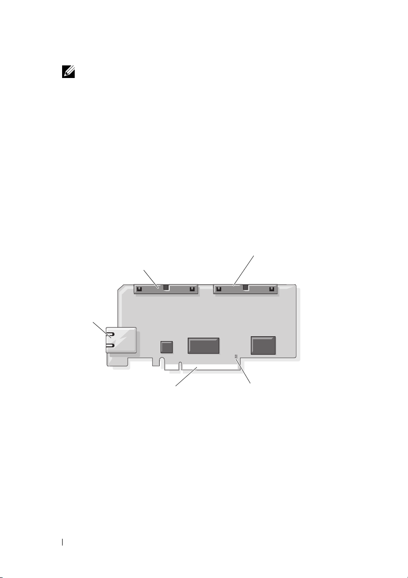
DRAC 5 Hardware Features
Figure 1-1 shows the DRAC 5 hardware.
Figure 1-1. DRAC 5 Hardware Features
44-pin MII cable
connector
RJ-45
Connector
PCIe Connector
50-pin management
cable connector
Jumper Connector
Hardware Specifications
Power Specifications
Table 1-1 lists the power requirements for the DRAC 5.
22 DRAC 5 Overview
Page 23

Table 1-1. DRAC 5 Power Specifications
System Power
1.2 A on +3.3 V AUX (maximum)
550 mA on +3.3 V main (maximum)
0 mA on +5V main (maximum)
Connectors
NOTE: The DRAC 5 hardware installation instructions can be found in the
a Remote Access Card
included with your system.
document or the
Installation and Troubleshooting Guide
Installing
The DRAC 5 includes one onboard 10/100 Mbps RJ-45 NIC, a 50-pin
management cable, and a 44-pin MII cable. See Figure 1-1 for the DRAC 5
cable connectors.
The 50-pin management cable is the main interface to the DRAC that
provides connectivity to USB, serial, video, and an inter-integrated circuit
(I2C) bus. The 44-pin MII cable connects the DRAC NIC to the system’s
motherboard. The RJ-45 connector connects the DRAC NIC to an out-ofband connection when the DRAC 5 is configured in Dedicated NIC mode.
Using the management and MII cables, you can configure your DRAC in
three separate modes, depending on your needs. See "DRAC Modes" on
page 225 in "Using the RACADM Command Line Interface" on page 209 for
more information.
DRAC 5 Ports
Table 1-2 identifies the ports used by the DRAC 5 that listen for a server
connection. Table 1-3 identifies the ports that the DRAC 5 uses as a client.
This information is required when opening firewalls for remote access to a
DRAC 5.
Table 1-2. DRAC 5 Server Listening Ports
Port Number Function
22*
23*
Secure Shell (SSH)
Te ln e t
DRAC 5 Overview 23
Page 24

Table 1-2. DRAC 5 Server Listening Ports
Port Number Function
80*
161
443*
623
3668*
3669*
5900*
5901*
* Configurable port
Table 1-3. DRAC 5 Client Ports
Port Number Function
25
53
68
69
162
636
3269
HTTP
SNMP Agent
HTTPS
RMCP/RMCP+
Virtual Media server
Virtual Media Secure Service
Console Redirection keyboard/mouse
Console Redirection video
SMTP
DNS
DHCP-assigned IP address
TFTP
SNMP trap
LDAPS
LDAPS for global catalog (GC)
(continued)
Supported Remote Access Connections
Table 1-4 lists the connection features.
24 DRAC 5 Overview
Page 25

Table 1-4. Supported Remote Access Connections
Connection Features
DRAC 5 NIC
Serial port
• 10/100 Mbps Ethernet
• DHCP support
• SNMP traps and e-mail event notification
• Dedicated network interface for the DRAC 5 Web-based
interface
• Support for telnet/ssh console and RACADM CLI commands
including system boot, reset, power-on, and shutdown
commands
• Support for Serial console and RACADM CLI commands
including system boot, reset, power-on, and shutdown
commands
• Support for text-only console redirection to a VT-100 terminal
or terminal emulator
DRAC 5 Security Features
The DRAC 5 provides the following security features:
• Two-factor authentication, which is provided by the Smart Card logon.
The two-factor authentication is based on what the users have (the Smart
Card) and what they know (the PIN).
• Advanced Security options for the DRAC administrator:
• The Console Redirection disable option allows the
disable console redirection using the DRAC 5 Console Redirection
feature.
• The local configuration disable features allows the
administrator to selectively disable the ability to configure the
DRAC 5 from:
– BIOS POST option-ROM
– operating system using the local racadm
– Dell OpenManage™ Server Administrator utilities
local
system user to
remote
DRAC
DRAC 5 Overview 25
Page 26

• User authentication through Microsoft Active Directory (optional) or
hardware-stored user IDs and passwords
• Role-based authority, which enables an administrator to configure specific
privileges for each user
• User ID and password configuration through the Web-based interface or
RACADM CLI
• RACADM CLI and Web-based interface operation, which supports 128bit SSL encryption and 40-bit SSL encryption (for countries where 128 bit
is not acceptable)
NOTE: Telnet does not support SSL encryption.
• Session time-out configuration (in seconds) through the Web-based
interface or RACADM CLI
• Configurable IP ports (where applicable)
• Secure Shell (SSH), which uses an encrypted transport layer for higher
security.
• Login failure limits per IP address, with login blocking from the IP address
when the limit is exceeded.
• Limited IP address range for clients connecting to the DRAC 5
Supported Platforms
The DRAC 5 supports the following Dell systems:
• 1900
• 1950
• 2900
• 2950
• 2970
• 6950
•R300
•R600
•T600
• M605
26 DRAC 5 Overview
Page 27

• R805
• R900
• R905
• T300
• PowerVault™ 500
• PowerVault 600
NOTE: The PowerEdge R805 is scheduled to be available in Q4 CY07–Q1 CY08.
See the Dell Systems Software Support Matrix located on the Dell Support
website at support.dell.com for the latest supported platforms.
Supported Operating Systems
Table 1-5 lists the operating systems that support the DRAC 5.
See the Dell Systems Software Support Matrix located on the Dell Support
website at support.dell.com for the latest information.
DRAC 5 Overview 27
Page 28

Table 1-5. Supported Operating Systems
Operating System
Family
Microsoft
Windows
Operating System
Microsoft Windows Server™ 2008 Web, Standard, Enterprise,
and Core Edition (x86)
Microsoft Windows Server 2008 Standard, Enterprise,
DataCenter, and Core Edition (x64)
Windows 2000 Advanced Server with Service Pack 4 (SP4)
Windows 2000 Server with SP4
Windows Server 2003 R2 Standard and Enterprise Editions with
SP2 (32-bit)
Windows Server 2003 Web Edition with SP2 (32-bit)
Windows Server 2003 R2 Standard and Enterprise Editions with
SP2 (x86_64)
Windows Server 2003 Standard and Enterprise X64 Editions with
SP1 and SP2
Windows Storage Server 2003 R2 Workgroup, Standard, and
Enterprise x64 Editions (x86_64)
Windows Unified Data Storage Server 2003 Gold Standard and
Enterprise X64 Editions (x86_64)
Windows Vista™
NOTE: When installing Windows Server 2003 with Service Pack 1,
be aware of changes to DCOM security settings. For more
information, see article 903220 from the Microsoft Support website
at support.microsoft.com/kb/903220.
28 DRAC 5 Overview
Page 29

Table 1-5. Supported Operating Systems
(continued)
Operating System
Family
Red Hat® Linux Enterprise Linux® WS, ES, and AS (version 3) (x86 and x86_64)
Operating System
Enterprise Linux WS, ES, and AS (version 4) (ia32 and x86_64)
Enterprise Linux WS, ES, and AS (version 4) (x86 and x86_64)
Enterprise Linux WS, ES, and AS (Version 4.5) (x86)
Enterprise Linux WS, ES, and AS (Version 4.5) (x86_64)
Enterprise Linux WS and AS (Version 4.5) (ia64)
Enterprise Linux 5 (x86 and x86-64)
NOTE: When using DRAC 5 with Red Hat Enterprise Linux (version 5)
systems, support is limited to a managed node and racadm CLI;
managed console (web-based interface) is not supported.
SUSE® Linux Linux Enterprise Server 9 with SP3 (x86_64)
Linux Enterprise Server 9 with Update 2 and 3 (x86_64)
Linux Enterprise Server 10 (Gold) (x86_64).
Supported Web Browsers
NOTICE: Console Redirection and Virtual Media only supports 32-bit Web
browsers. Using 64-bit Web browsers may generate unexpected results or failure of
operations.
Table 1-6 lists the Web browsers that support the DRAC 5.
See the Dell System Software Support Matrix located on the Dell Support
website at support.dell.com for the latest information.
DRAC 5 Overview 29
Page 30

Table 1-6. Supported Web Browsers
Operating System Supported Web Browser
Windows Internet Explorer 6.0 (32-bit) with Service Pack 2
(SP2) for Windows XP and Windows 2003 R2 SP2
only.
Internet Explorer 7.0 for Windows Vista, Windows
XP, and Windows 2003 R2 SP2 only.
To view localized versions of the DRAC 5 Web-based
interface:
1
Open the Windows
2
Double-click the
3
Select the desired locale from the
(location)
NOTICE: If you are running the Virtual Media
Linux Mozilla Firefox 1.5 (32-bit) on SUSE Linux (version
10) only.
Mozilla Firefox 2.0 (32-bit).
drop-down menu.
client, you must use Internet Explorer 6.0 with
Service Pack 1 or later.
Control Panel
Regional Options
.
icon.
Your locale
Disabling the Whitelist Feature in Mozilla Firefox
Firefox includes a "whitelist" feature that provides additional security. When
the whitelist feature is enabled, the browser requires user permission to install
plug-ins for each distinct site that hosts the plug-in. This process requires
that you install a plug-in for each distinct RAC IP/DNS name, even though
the plug-in versions are identical.
To disable the whitelist feature and avoid repetitive, unnecessary plugin
installations, perform the following steps:
1
Open a Firefox Web browser window.
2
In the address field, type the following and press <Enter>:
about:config
30 DRAC 5 Overview
Page 31

3
In the
Preference Name
xpinstall.whitelist.required
The values for
text. The
false
.
4
In the
Ensure that
Va l u e
to
Preferences Name
Preference Name, Status, Ty p e
Status
value changes to
Va l ue
true
.
column, locate and double-click
.
user set
and the
column, locate
is
true
. If not, double-click
xpinstall.enabled
, and
Va l u e
change to bold
Va l ue
value changes to
.
xpinstall.enabled
to set
Features
The DRAC 5 provides the following features:
• Dynamic Domain Name System (DNS) registration
• Remote system management and monitoring using a Web-based interface,
serial connection, remote RACADM, or telnet connection.
• Support for Active Directory authentication — Centralizes all DRAC 5
user ID and passwords in Active Directory using Standard Schema and
Extended Schema.
• Console Redirection — Provides remote system keyboard, video, and
mouse functions.
• Virtual Media — Enables a managed system to access a media drive on the
management station.
• Access to system event logs — Provides access to the system event log
(SEL), DRAC 5 log, and last crash screen of the crashed or unresponsive
system that is independent of the operating system state.
• Dell OpenManage software integration — Enables you to launch the
DRAC5 Web-based interface from Dell OpenManage Server
Administrator or IT Assistant.
• RAC alert — Alerts you to potential managed node issues through e-mail
messages or an SNMP trap using the
Shared
NIC settings.
• Local and remote configuration — Provides local and remote
configuration using the RACADM command-line utility.
Dedicated, Shared with Failover
, or
DRAC 5 Overview 31
Page 32

• Remote power management — Provides remote power management
functions from a management console, such as shutdown and reset.
•IPMI support.
• Secure Sockets Layer (SSL) encryption — Provides secure remote system
management through the Web-based interface.
• Password-level security management — Prevents unauthorized access to a
remote system.
• Role-based authority — Provides assignable permissions for different
systems management tasks.
Other Documents You May Need
In addition to this User’s Guide, the following documents provide additional
information about the setup and operation of the DRAC 5 in your system:
• DRAC 5 online help provides information about using the Web-based
interface.
•The
•The
•The
•The
•The
•The
Dell OpenManage™ IT Assistant User’s Guide
OpenManage IT Assistant Reference Guide
Assistant.
Dell OpenManage Server Administrator’s User’s Guide
information about installing and using Server Administrator.
Dell OpenManage Server Administrator SNMP Reference Guide
documents the Server Administrator SNMP management information
base (MIB). The MIB defines variables that extend the standard MIB to
cover the capabilities of systems management agents.
Dell OpenManage Baseboard Management Controller Utilities User’s
Guide
provides information about configuring the Baseboard Management
Controller (BMC), configuring your managed system using the BMC
Management Utility, and additional BMC information.
Dell Update Packages User's Guide
and using Dell Update Packages as part of your system update strategy.
Dell Systems Software Support Matrix
various Dell systems, the operating systems supported by these systems,
and the Dell OpenManage components that can be installed on these
systems.
provide information about IT
provides information about obtaining
provides information about the
and the
Dell
provides
32 DRAC 5 Overview
Page 33

The following system documents are also available to provide more
information about the system in which your DRAC 5 is installed:
•The
Product Information Guide
provides important safety and regulatory
information. Warranty information may be included within this document
or as a separate document.
•The
Rack Installation Guide
and
Rack Installation Instructions
included
with your rack solution describes how to install your system into a rack.
•The
Getting Started Guide
provides an overview of system features, setting
up your system, and technical specifications.
•The
Hardware Owner’s Manual
provides information about system
features and describes how to troubleshoot the system and install or
replace system components.
• Systems management software documentation describes the features,
requirements, installation, and basic operation of the software.
• Operating system documentation describes how to install (if necessary),
configure, and use the operating system software.
• Documentation for any components you purchased separately provides
information to configure and install these options.
• Updates are sometimes included with the system to describe changes to
the system, software, and/or documentation.
NOTE: Always read the updates first because they often supersede
information in other documents.
• Release notes or readme files may be included to provide last-minute
updates to the system or documentation or advanced technical reference
material intended for experienced users or technicians.
DRAC 5 Overview 33
Page 34

34 DRAC 5 Overview
Page 35

2
Installing and Setting Up the DRAC 5
This section provides information about how to install and setup your DRAC
5 hardware and software.
Before You Begin
Gather the following items that were included with your system prior to
installing and configuring the DRAC 5 software:
• DRAC 5 hardware (currently installed or in the optional kit)
• DRAC 5 installation procedures (located in this chapter)
•
Dell Systems Console and Agent
•
Dell Systems Documentation
•
Dell Systems Service and Diagnostic Tools
Installing the DRAC 5 Hardware
NOTE: The DRAC 5 connection emulates a USB keyboard connection. As a result,
when you restart the system, the system will not notify you if your keyboard is not
attached.
The DRAC 5 may be preinstalled on your system, or available separately in a
kit. To get started with the DRAC 5 that is installed on your system, see
"Software Installation and Configuration Overview" on page 37.
If a DRAC 5 is not installed on your system, see the Installing a Remote Access
Card
document that is included with your DRAC 5 kit, or see your platform
Installation and Troubleshooting Guide for hardware installation instructions.
CD
CD
CD
NOTE: See the
for information about removing the DRAC 5. Also, review all Microsoft® Active
Directory
security if you are using extended schema.
Installation and Troubleshooting Guide
®
RAC properties associated with the removed DRAC 5 to ensure proper
Installing and Setting Up the DRAC 5 35
included with your system
Page 36

Configuring Your System to Use a DRAC 5
To configure your system to use a DRAC 5, use the Dell™ Remote Access
Configuration Utility (formerly known as the BMC Setup Module).
To run the Dell Remote Access Configuration Utility, perform the following steps:
1
Turn on or restart your system.
2
Press <Ctrl><E> when prompted during POST.
If your operating system begins to load before you press <Ctrl><E>, allow
the system to finish booting, and then restart your system and try again.
3
Configure the NIC.
a
Using the down-arrow key, highlight
b
Using the left-arrow and right-arrow keys, select one of the following
NIC selections:
•
Dedicated
device to utilize the dedicated network interface available on the
Remote Access Controller (RAC). This interface is not shared
with the host operating system and routes the management traffic
to a separate physical network, enabling it to be separated from
the application traffic. This option is available only if a DRAC
card is installed in the system.
•
Shared
host operating system. The remote access device network interface
is fully functional when the host operating system is configured for
NIC teaming. The remote access device receives data through NIC
1 and NIC 2, but transmits data only through NIC 1. If NIC 1 fails,
the remote access device will not be accessible.
•
Failover
the host operating system. The remote access device network
interface is fully functional when the host operating system is
configured for NIC teaming. The remote access device receives
data through NIC 1 and NIC 2, but transmits data only through
NIC 1. If NIC 1 fails, the remote access device fails over to NIC 2
for all data transmission. The remote access device continues to
use NIC 2 for data transmission. If NIC 2 fails, the remote access
device fails over all data transmission back to NIC 1.
— Select this option to enable the remote access
— Select this option to share the network interface with the
— Select this option to share the network interface with
NIC Selection
.
36 Installing and Setting Up the DRAC 5
Page 37

4
Configure the network controller LAN parameters to use DHCP or a
Static IP address source.
a
Using the down-arrow key, select
b
Using the up-arrow and down-arrow keys, select
c
Using the right-arrow and left-arrow keys, select
d
If you selected
Mask
e
Press <Esc>.
5
Press <Esc>.
6
Select
Static
, configure the
, and
Default Gateway
Save Changes and Exit
LAN Parameters
settings.
.
, and press <Enter>.
IP Address Source
DHCP
or
Static
Ethernet IP Address, Subnet
.
.
The system automatically reboots.
NOTE: When viewing the Web user interface on a Dell PowerEdge™ 1900 system
that is configured with one NIC, the NIC Configuration page displays two NICs (NIC1
and NIC2). This behavior is normal. The PowerEdge 1900 system (and other Dell
systems that are configured with a single LAN On Motherboard) can be configured
with NIC teaming. Shared and Teamed modes work independently on these systems.
See the Dell OpenManage Baseboard Management Controller Utilities User’s
Guide for more information about the Dell Remote Access Configuration Utility.
Software Installation and Configuration Overview
This section provides a high-level overview of the DRAC 5 software
installation and configuration process. Configure your DRAC 5 using the
Web-based interface, RACADM CLI, or Serial/Telnet/SSH console.
For more information about the DRAC 5 software components, see
"Installing the Software on the Managed System" on page 38.
Installing Your DRAC 5 Software
To install your DRAC 5 software, perform the following steps in order:
1
Install the software on the managed system. See "Installing the Software
on the Managed System" on page 38.
2
Install the software on the management station. See "Installing the
Software on the Management Station" on page 40.
Installing and Setting Up the DRAC 5 37
Page 38

Configuring Your DRAC 5
To configure your DRAC 5, perform the following steps in order:
1
Select one of the following configuration tools:
• Web-based interface
•RACADM CLI
• Serial/Telnet/SSH console
NOTICE: Using more than one DRAC 5 configuration tool at the same time may
generate unexpected results.
2
Configure the DRAC 5 network settings. See "Configuring the DRAC 5
Network Settings" on page 45.
3
Add and configure DRAC 5 users. See "Adding and Configuring DRAC 5
Users" on page 46.
4
Configure the Web browser to access the Web-based interface. See
"Configuring a Supported Web Browser" on page 42.
5
Disable the Windows® Automatic Reboot Option. See "Disabling the
Windows Automatic Reboot Option" on page 39.
6
Update the DRAC 5 Firmware. See "Updating the DRAC 5 Firmware" on
page 46.
7
Access the DRAC 5 through a network. See "Accessing the DRAC 5
Through a Network" on page 48.
Installing the Software on the Managed System
Installing software on the managed system is optional. Without managed
system software, you lose the ability to use the RACADM locally, and for the
RAC to capture the last crash screen.
To install the managed system software, install the software on the managed
system using the
how to install this software, see your Quick Installation Guide.
Managed system software installs your choices from the appropriate version
of Server Administrator on the managed system.
NOTE: Do not install the DRAC 5 management station software and the DRAC 5
managed system software on the same system.
38 Installing and Setting Up the DRAC 5
Dell Systems Console and Agent
CD
. For instructions about
Page 39

If Server Administrator is not installed on the managed system, you cannot
view the system’s last crash screen or use the Auto Recovery feature.
For more information about the last crash screen, see "Viewing the Last
System Crash Screen" on page 132.
Configuring the Managed System to Capture the Last Crash Screen
Before the DRAC 5 can capture the last crash screen, you must configure the
managed system with the following prerequisites.
1
Install the managed system software. For more information about installing
the managed system software, see the
2
Run a supported Microsoft® Windows® operating system with the
Windows "automatically reboot" feature deselected in the
Startup and Recovery Settings
3
Enable the Last Crash Screen (disabled by default).
To enable using local RACADM, open a command prompt and type the
following commands:
racadm config -g cfgRacTuning -o
cfgRacTuneAsrEnable 1
4
Enable the Auto Recovery timer and set the
Reset, Power Off
you must use Server Administrator or IT Assistant.
For information about how to configure the
Server Administrator User's Guide
be captured, the
The default setting is 480 seconds.
, or
Power Cycle
Auto Recovery
Server Administrator User's Guide
Windows
.
Auto Recovery
. To configure the
Auto Recovery
. To ensure that the last crash screen can
timer must be set to 60 seconds or greater.
action to
Auto Recovery
timer, see the
timer,
.
The last crash screen is not available when the
to
Shutdown
or
Power Cycle
if the managed system is powered off.
Auto Recovery
action is set
Disabling the Windows Automatic Reboot Option
To ensure that the DRAC 5 Web-based interface last crash screen feature
works properly, disable the Automatic Reboot option on managed systems
running the Microsoft Windows Server 2003 and Windows 2000 Server
operating systems.
Installing and Setting Up the DRAC 5 39
Page 40

Disabling the Automatic Reboot Option in Windows Server 2003
1
Open the Windows
2
Click the
3
Under
4
Deselect the
5
Click OK twice.
Disabling the Automatic Reboot Option in Windows 2000 Server
1
Open the Windows
2
Click the
3
Click the
4
Deselect the
Advanced
Startup and Recovery
Advanced
Startup and Recovery...
Control Panel
tab.
, click
Automatically Reboot
Control Panel
tab.
button.
Automatically Reboot
and double-click the
Settings
and double-click the
.
check box.
check box.
System
System
icon.
icon.
Installing the Software on the Management Station
Your system includes the Dell OpenManage System Management Software Kit.
This kit includes, but is not limited to, the following components:
•
Dell Systems Build and Update Utility
the tools you need to install your operating system, configure and update
your system. The CD enables you to streamline Dell system deployment
and redeployment.
•
Dell Systems Console and Agent
management software products such as Dell OpenManage Server
Administrator and console products including Dell OpenManage IT Assistant.
•
Dell Systems Service and Diagnostics Tools
need to configure your system and delivers the latest BIOS, firmware,
diagnostics, and Dell-optimized drivers for your system.
•
Dell Systems Documentation
documentation for systems, systems management software products,
peripherals, and RAID controllers.
CD — Helps you stay current with
CD — A bootable CD that provides
CD — Contains all the latest Dell systems
CD — Provides the tools you
NOTE: Starting with Dell OpenManage version 5.3, you can also obtain all the
above components from the
DVD and the
40 Installing and Setting Up the DRAC 5
Dell Server Updates
Dell Systems Management Tools and Documentation
DVD.
Page 41

For information about installing Server Administrator software, see your
Server Administrator User's Guide.
Configuring Your Red Hat Enterprise Linux (Version 4) Management Station
The Dell Digital KVM Viewer requires additional configuration to run on a
Red Hat Enterprise Linux (version 4) management station. When you install
the Red Hat Enterprise Linux (version 4) operating system on your
management station, perform the following procedures:
• When prompted to add or remove packages, install the optional
Software Development
software. This software package includes the
Legacy
necessary software components to run the Dell Digital KVM viewer on
your management station.
• To ensure that the Dell Digital KVM Viewer functions properly, open the
following ports on your firewall:
– Keyboard and mouse port (default is port 5900)
– Video port (default is port 5901)
Installing and Removing RACADM on a Linux Management Station
To use the remote RACADM functions, install RACADM on a management
station running Linux.
NOTE: When you run Setup on the
RACADM utility for all supported operating systems are installed on your
management station.
Dell Systems Console and Agent
Installing RACADM
1
Log on as root to the system where you want to install the management
station components.
2
If necessary, mount the
following command or a similar command:
mount /media/cdrom
3
Navigate to the
/linux/rac
rpm -ivh *.rpm
Dell Systems Console and Agent CD
using the
directory and execute the following command:
Installing and Setting Up the DRAC 5 41
CD, the
Page 42

For help with the RACADM command, type racadm help after issuing the
previous commands. For more information about RACADM, see "Using the
RACADM Command Line Interface" on page 209.
Uninstalling RACADM
To uninstall RACADM, open a command prompt and type:
rpm -e <racadm_package_name>
where <racadm_package_name> is the rpm package that was used to
install the RAC software.
For example, if the rpm package name is srvadmin-racadm5, then type:
rpm -e srvadmin-racadm5
Configuring a Supported Web Browser
The following sections provide instructions for configuring the supported
Web browsers. For a list of supported Web browsers, see "Supported Web
Browsers" on page 29.
Configuring Your Web Browser to Connect to the Web-Based Interface
If you are connecting to the DRAC 5 Web-based interface from a
management station that connects to the Internet through a proxy server, you
must configure the Web browser to access the Internet from this server.
To configure your Internet Explorer Web browser to access a proxy server,
perform the following steps:
1
Open a Web browser window.
2
Click
Tools
3
From the
4
Under
Local Area Network (LAN) settings
5
If the
Use a proxy server
local addresses
6
Click OK twice.
, and click
Internet Options
box.
Internet Options
window, click the
box is selected, select the
.
, click
Connections
LAN Settings
Bypass proxy server for
tab.
.
42 Installing and Setting Up the DRAC 5
Page 43

List of Trusted Domains
When you access the DRAC 5 Web-based interface through the Web
browser, you are prompted to add the DRAC 5 IP address to the list of trusted
domains if the IP address is missing from the list. When completed, click
Refresh or relaunch the Web browser to reestablish a connection to the
DRAC 5 Web-based interface.
32-bit and 64-bit Web Browsers
The DRAC 5 Web-based interface is not supported on 64-bit Web browsers.
If you open a 64-bit Browser, access the Console Redirection page, and
attempt to install the plug-in, the installation procedure fails. If this error was
not acknowledged and you repeat this procedure, the Console Redirect Page
loads even though the plug-in installation fails during your first attempt. This
issue occurs because the Web browser stores the plug-in information in the
profile directory even though the plug-in installation procedure failed. To fix
this issue, install and run a supported 32-bit Web browser and log in to the
DRAC 5.
Viewing Localized Versions of the Web-Based Interface
Windows
The DRAC 5 Web-based interface is supported on the following Windows
operating system languages:
•English
•French
•German
•Spanish
• Japanese
• Simplified Chinese
To view a localized version of the DRAC 5 Web-based interface in Internet
Explorer, perform the following steps:
1
Click the
2
In the
3
In the
Tools
menu and select
Internet Options
Language Preference
window, click
Internet Options
Languages
window, click
Add
.
.
.
Installing and Setting Up the DRAC 5 43
Page 44

4
In the
Add Language
window, select a supported language.
To select more than one language, press <Ctrl>.
5
Select your preferred language and click
Move Up
to move the language to
the top of the list.
6
Click OK.
7
In the
Language Preference
Linux
window, click OK.
If you are running Console Redirection on a Red Hat Enterprise Linux
(version 4) client with a Simplified Chinese GUI, the viewer menu and title
may appear in random characters. This issue is caused by an incorrect
encoding in the Red Hat Enterprise Linux (version 4) Simplified Chinese
operating system. To fix this issue, access and modify the current encoding
settings by performing the following steps:
1
Open a command terminal.
2
Type “locale” and press <Enter>. The following output appears.
LANG=zh_CN.UTF-8
LC_CTYPE="zh_CN.UTF-8"
LC_NUMERIC="zh_CN.UTF-8"
LC_TIME="zh_CN.UTF-8"
LC_COLLATE="zh_CN.UTF-8"
LC_MONETARY="zh_CN.UTF-8"
LC_MESSAGES="zh_CN.UTF-8"
LC_PAPER="zh_CN.UTF-8"
LC_NAME="zh_CN.UTF-8"
LC_ADDRESS="zh_CN.UTF-8"
LC_TELEPHONE="zh_CN.UTF-8"
LC_MEASUREMENT="zh_CN.UTF-8"
LC_IDENTIFICATION="zh_CN.UTF-8"
LC_ALL=
3
If the values include “zh_CN.UTF-8”, no changes are required. If the
values do not include “zh_CN.UTF-8”, go to step 4.
4
Navigate to the /etc/sysconfig/i18n file.
44 Installing and Setting Up the DRAC 5
Page 45

5
In the file, apply the following changes:
Current entry:
LANG="zh_CN.GB18030"
SUPPORTED="zh_CN.GB18030:zh_CH.GB2312:zh_CN:zh"
Updated entry:
LANG="zh_CN.UTF-8"
SUPPORTED="zh_CN.UTF8:zh_CN.GB18030:zh_CH.GB2312:zh_CN:zh"
6
Log out and then login to the operating system.
7
Relaunch the DRAC 5.
When you switch from any other language to the Simplified Chinese
language, ensure that this fix is still valid. If not, repeat this procedure.
Configuring DRAC 5 Properties
Configure the DRAC 5 properties (network, users, alerts, etc.) using the
Web-based interface or RACADM.
For more information about using the Web-based interface, see "Accessing
the Web-Based Interface" on page 91. For more information about using
RACADM in a serial or telnet connection, see "Using the RACADM
Command Line Interface" on page 209.
Configuring the DRAC 5 Network Settings
NOTICE: Changing your DRAC 5 Network settings may disconnect your current
network connection.
Configure the DRAC 5 network settings using one of the following tools:
• Web-based Interface — See "Configuring the DRAC 5 NIC" on page 93
• RACADM CLI — See "cfgLanNetworking" on page 295
•
Dell Remote Access Configuration Utility — See
System to Use a DRAC 5" on page 36
NOTE: If you are deploying the DRAC 5 in a Linux environment, see "Installing
RACADM" on page 41.
Installing and Setting Up the DRAC 5 45
"Configuring Your
Page 46

Adding and Configuring DRAC 5 Users
Use one of the following tools to add and configure DRAC 5 users:
• Web-based interface — See "Adding and Configuring DRAC 5 Users" on
page 98.
• RACADM CLI — See "cfgUserAdmin" on page 305.
Updating the DRAC 5 Firmware
Use one of the following methods to update your DRAC 5 firmware.
• Web-based Interface — See "Updating the DRAC 5 Firmware Using the
Web-Based Interface" on page 47.
• RACADM CLI — See "fwupdate" on page 253.
• Dell Update Packages — See the
information about obtaining and using Dell Update Packages as part of
your system update strategy
Before You Begin
Before you update your DRAC 5 firmware using local RACADM or the Dell
Update Packages, perform the following procedures. Otherwise, the firmware
update operation may encounter a failure.
1
Install and enable the appropriate IPMI and managed node drivers.
2
If your system is running the Windows operating system, enable and start
the
Windows Management Instrumentation
3
If your system is running SUSE Linux Enterprise Server (Version 10) for
Intel EM64T, start the
4
Ensure that the RAC virtual flash is unmounted or not in use by the
operating system or another application or user.
5
Disconnect and unmount Virtual Media.
6
Ensure that USB is enabled.
Raw
Dell Update Packages User's Guide
(WMI) services.
service.
for
46 Installing and Setting Up the DRAC 5
Page 47

Downloading the DRAC 5 Firmware
To update your DRAC 5 firmware, download the latest firmware from the
Dell Support website located at support.dell.com and save the file to your
local system.
The following software components are included with your DRAC 5 firmware
package:
• Compiled DRAC 5 firmware code and data
• Expansion ROM image
• Web-based interface, JPEG, and other user interface data files
• Default configuration files
Use the Firmware Update page to update the DRAC 5 firmware to the latest
revision. When you run the firmware update, the update retains the current
DRAC 5 settings.
Updating the DRAC 5 Firmware Using the Web-Based Interface
1
Open the Web-based interface and login to the remote system.
See "Accessing the Web-Based Interface" on page 91.
2
In the
System
tree, click
3
In the
Firmware Update
to the firmware image that you downloaded from
Browse
to navigate to the image.
Remote Access
page in the
Firmware Image
and click the
support.dell.com
Update
tab.
field, type the path
or click
NOTE: If you are running Firefox, the text cursor does not appear in the
Firmware Image field.
For example:
C:\Updates\V1.0\<
The default firmware image name is
4
Click
Update
.
image_name>.
firmimg.d5
.
The update may take several minutes to complete. When completed, a
dialog box appears.
5
Click OK to close the session and automatically log out.
6
After the DRAC 5 resets, click
Log In
to log in to the DRAC 5.
Installing and Setting Up the DRAC 5 47
Page 48

Clearing the Browser Cache
After the firmware upgrade, clear the Web browser cache.
See your Web browser’s online help for more information.
Accessing the DRAC 5 Through a Network
After you configure the DRAC 5, you can remotely access the managed
system using one of the following interfaces:
• Web-based interface
•RACADM
•Telnet Console
• SSH
•IPMI
Table 2-1 describes each DRAC 5 interface.
Table 2-1. DRAC 5 Interfaces
Interface Description
Web-based interface Provides remote access to the DRAC 5 using a graphical
user interface. The Web-based interface is built into
the DRAC 5 firmware and is accessed through the NIC
interface from a supported Web browser on the
management station.
For a list of supported Web browsers, see "Supported
Web Browsers" on page 29.
48 Installing and Setting Up the DRAC 5
Page 49

Table 2-1. DRAC 5 Interfaces
Interface Description
RACADM Provides remote access to the DRAC 5 using a
(continued)
command line interface. RACADM uses the managed
system’s IP address to execute RACADM commands
(racadm remote capability option [-r]).
NOTE: The racadm remote capability is supported only on
management stations. For more information, see
"Supported Web Browsers" on page 29.
NOTE: When using the racadm remote capability, you
must have write permission on the folders where you are
using the racadm subcommands involving file operations,
for example:
racadm getconfig -f <file name>
or:
racadm sslcertupload -t 1 -f
c:\cert\cert.txt subcommands
Telnet Console Provides access through the DRAC 5 to the server RAC
port and hardware management interfaces through the
DRAC 5 NIC and provides support for serial and
RACADM commands including powerdown, powerup,
powercycle, and hardreset commands.
NOTE: Telnet is an unsecure protocol that transmits all
data—including passwords—in plain text. When
transmitting sensitive information, use the SSH interface.
SSH Interface Provides the same capabilities as the telnet console
using an encrypted transport layer for higher security.
IPMI Interface Provides access through the DRAC 5 to the remote
system’s basic management features. The interface
includes IPMI over LAN, IPMI over Serial, and Serial
over LAN. See the Dell OpenManage Baseboard
Management Controller User’s Guide for more
information.
NOTE: The DRAC 5 default user name is root and the default password is
calvin.
Installing and Setting Up the DRAC 5 49
Page 50

You can access the DRAC 5 Web-based interface through the DRAC 5 NIC
by using a supported Web browser, or through Server Administrator or
IT Assistant.
See "Supported Web Browsers" on page 29 for a list of supported Web
browsers.
To access the DRAC 5 using a supported Web browser, see "Accessing the
Web-Based Interface" on page 91.
To access the DRAC 5 remote access interface using Server Administrator,
launch Server Administrator. From the system tree on the left pane of the
Server Administrator home page, click System → Main System Chassis→
Remote Access Controller. For more information, see your Server
Administrator User’s Guide.
For information about accessing the DRAC 5 using RACADM, see "Using the
RACADM Command Line Interface" on page 209.
Configuring IPMI
This section provides information about configuring and using the DRAC 5
IPMI interface. The interface includes the following:
• IPMI over LAN
• IPMI over Serial
• Serial over LAN
The DRAC5 is fully IPMI 2.0 compliant. You can configure the DRAC IPMI
using your browser; using an open source utility, such as ipmitool; using the
Dell OpenManage IPMI shell, ipmish; or using RACADM.
For more information about using the IPMI Shell, ipmish, see the Dell
OpenManage™ BMC User's Guide located on the Dell Support website at
support.dell.com.
For more information about using RACADM, see "Using RACADM" on
page 210.
50 Installing and Setting Up the DRAC 5
Page 51

Configuring IPMI Using the Web-Based Interface
1
Login to the remote system using a supported Web browser.
See "Accessing the Web-Based Interface" on page 91.
2
Configure IPMI over LAN.
a
In the
System
tree, click
b
c
Click the
In the
Configuration
Network Configuration
Enable IPMI Over LAN
d
Update the IPMI LAN channel privileges, if required.
NOTE: This setting determines the IPMI commands that can be executed
from the IPMI over LAN interface. For more information, see the IPMI 2.0
specifications.
Under
IPMI LAN Settings
drop-down menu, select
Apply Changes
e
Set the IPMI LAN channel encryption key, if required.
NOTE: The DRAC 5 IPMI supports the RMCP+ protocol.
Under
IPMI LAN Settings
.
encryption key and click
NOTE: The encryption key must consist of an even number of hexadecimal
characters with a maximum of 40 characters.
3
Configure IPMI Serial over LAN (SOL).
a
In the
System
tree, click
b
In the
Configuration
c
In the
Serial Over LAN Configuration
Over LAN
d
Update the IPMI SOL baud rate.
.
Remote Access
tab and click
.
Network
page under
and click
, click the
Apply Changes
Channel Privilege Level Limit
Administrator, Operator
in the
Encryption Key field
Apply Changes
Remote Access
tab, click
Serial Over LAN
.
.
page, select
IPMI LAN Settings
.
.
, or
User
.
Enable Serial
, select
and click
, type the
NOTE: To redirect the serial console over LAN, ensure that the SOL baud rate
is identical to your managed system’s baud rate.
e
Click the
rate, and click
Baud Rate
Apply Changes
drop-down menu, select the appropriate baud
.
Installing and Setting Up the DRAC 5 51
Page 52

f
Update the
minimum user privilege that is required to use the
feature.
Click the
User, Operator
g
Click
Apply Changes
4
Configure IPMI Serial.
a
In the
Configuration
b
In the
Serial Configuration
mode to the appropriate setting.
Under
IPMI Serial
menu, select the appropriate mode.
c
Set the IPMI Serial baud rate.
Click the
Baud Rate
rate, and click
d
Set the Channel Privilege Level Limit.
Click the
Administrator, Operator
e
Click
Apply Changes
f
Ensure that the serial MUX is set correctly in the managed system’s
BIOS Setup program.
• Restart your system.
• During POST, press <F2> to enter the BIOS Setup program.
•Navigate to
•In the
Connector
• Save and exit the BIOS Setup program.
• Restart your system.
Minimum Required Privilege
Channel Privilege Level Limit
, or
Administrator
.
.
tab, click
Serial
.
menu, change the IPMI serial connection
, click the
Connection Mode Setting
drop-down menu, select the appropriate baud
Apply Changes
.
Channel Privilege Level Limit
, or
User
.
.
Serial Communication
Serial Connection
is set to
menu, ensure that
Remote Access Device
. This property defines the
Serial Over LAN
drop-down menu, select
drop-down
drop-down menu, select
.
External Serial
.
52 Installing and Setting Up the DRAC 5
Page 53

If IPMI serial is in terminal mode, you can configure the following
additional settings:
• Delete control
• Echo control
• Line edit
• New line sequences
• Input new line sequences
For more information about these properties, see the IPMI 2.0
specification.
Configuring IPMI Using the RACADM CLI
1
Login to the remote system using any of the RACADM interfaces. See
"Using RACADM" on page 210.
2
Configure IPMI over LAN.
Open a command prompt, type the following command, and press
<Enter>:
racadm config -g cfgIpmiLan -o cfgIpmiLanEnable 1
NOTE: This setting determines the IPMI commands that can be executed from the
IPMI over LAN interface. For more information, see the IPMI 2.0 specifications.
Update the IPMI channel privileges.
a
At the command prompt, type the following command and press
<Enter>:
racadm config -g cfgIpmiLan -o
cfgIpmiLanPrivilegeLimit
where
<level>
•
2
(User)
3
(Operator)
•
•
4
(Administrator)
is one of the following:
Installing and Setting Up the DRAC 5 53
<level>
Page 54

For example, to set the IPMI LAN channel privilege to 2 (User), type
the following command:
racadm config -g cfgIpmiLan -o
cfgIpmiLanPrivilegeLimit 2
b
Set the IPMI LAN channel encryption key, if required.
NOTE: The DRAC 5 IPMI supports the RMCP+ protocol. See the IPMI 2.0
specifications for more information.
At the command prompt, type the following command and press
<Enter>:
racadm config -g cfgIpmiLan -o
cfgIpmiEncryptionKey
where
<key>
is a 20-character encryption key in a valid hexadecimal
<key>
format.
3
Configure IPMI Serial over LAN (SOL).
At the command prompt, type the following command and press <Enter>:
racadm config -g cfgIpmiSol -o cfgIpmiSolEnable 1
a
Update the IPMI SOL minimum privilege level.
NOTICE: The IPMI SOL minimum privilege level determines the minimum
privilege required to activate IPMI SOL. For more information, see the IPMI 2.0
specification.
At the command prompt, type the following command and press
<Enter>:
racadm config -g cfgIpmiSol -o
cfgIpmiSolMinPrivilege
where
<level>
•
2
(User)
3
(Operator)
•
•
4
(Administrator)
is one of the following:
54 Installing and Setting Up the DRAC 5
<level>
Page 55

For example, to configure the IPMI privileges to 2 (User), type the
following command:
racadm config -g cfgIpmiSol -o
cfgIpmiSolMinPrivilege 2
b
Update the IPMI SOL baud rate.
NOTE: To redirect the serial console over LAN, ensure that the SOL baud rate
is identical to your managed system’s baud rate.
At the command prompt, type the following command and press
<Enter>:
racadm config -g cfgIpmiSol -o
cfgIpmiSolBaudRate
where
<baud_rate>
<baud_rate>
is 9600, 19200, 57600, or 115200 bps.
For example:
racadm config -g cfgIpmiSol -o
cfgIpmiSolBaudRate 57600
c
Enable SOL.
NOTE: SOL can be enabled or disabled for each individual user.
At the command prompt, type the following command and press
<Enter>:
racadm config -g cfgUserAdmin -o
cfgUserAdminSolEnable -i
where
<id>
4
Configure IPMI Serial.
a
Change the IPMI serial connection mode to the appropriate setting.
At the command prompt, type the following command and press
<Enter>:
racadm config -g cfgSerial -o
cfgSerialConsoleEnable 0
b
Set the IPMI Serial baud rate.
is the user’s unique ID.
Installing and Setting Up the DRAC 5 55
<id>
2
Page 56

Open a command prompt, type the following command, and press
<Enter>:
racadm config -g cfgIpmiSerial -o
cfgIpmiSerialBaudRate
where
<baud_rate>
is 9600, 19200, 57600, or 115200 bps.
<baud_rate>
For ex a m p l e:
racadm config -g cfgIpmiSerial -o
cfgIpmiSerialBaudRate 57600
c
Enable the IPMI serial hardware flow control.
At the command prompt, type the following command and press
<Enter>:
racadm config -g cfgIpmiSerial -o
cfgIpmiSerialFlowControl 1
d
Set the IPMI serial channel minimum privilege level.
At the command prompt, type the following command and press
<Enter>:
racadm config -g cfgIpmiSerial -o
cfgIpmiSerialChanPrivLimit
where
<level>
is one of the following:
<level>
•
2
(User)
•
3
(Operator)
4
(Administrator)
•
For example, to set the IPMI serial channel privileges to 2 (User), type
the following command:
racadm config -g cfgIpmiSerial -o
cfgIpmiSerialChanPrivLimit 2
56 Installing and Setting Up the DRAC 5
Page 57

e
Ensure that the serial MUX is set correctly in the BIOS Setup
program.
• Restart your system.
• During POST, press <F2> to enter the BIOS Setup program.
• Navigate to
•In the
Connector
• Save and exit the BIOS Setup program.
• Restart your system.
The IPMI configuration is complete.
If IPMI serial is in terminal mode, you can configure the following
additional settings using
• Delete control
•Echo control
• Line edit
• New line sequences
• Input new line sequences
For more information about these properties, see the IPMI 2.0
specification.
Serial Communication
Serial Connection
is set to
Remote Access Device
racadm config cfgIpmiSerial
.
menu, ensure that
.
External Serial
commands:
Configuring Platform Events
Platform event configuration provides a mechanism for configuring the
remote access device to perform selected actions on certain event messages.
These actions include reboot, power cycle, power off, and triggering an alert
(Platform Events Trap [PET] and/or e-mail).
The filterable Platform Events include the following:
•Fan Probe Failure
• Battery Probe Warning
• Battery Probe Failure
• Discrete Voltage Probe Failure
• Temperature Probe Warning
Installing and Setting Up the DRAC 5 57
Page 58

• Temperature Probe Failure
• Chassis Intrusion Detected
• Redundancy Degraded
•Redundancy Lost
•Processor Warning
• Processor Failure
• Processor Absent
• PS/VRM/D2D Warning
• PS/VRM/D2D Failure
• Power Supply Absent
•Hardware Log Failure
• Automatic System Recovery
When a platform event occurs (for example, a fan probe failure), a system
event is generated and recorded in the System Event Log (SEL). If this event
matches a platform event filter (PEF) in the Platform Event Filters list in the
Web-based interface and you have configured this filter to generate an alert
(PET or e-mail), then a PET or e-mail alert is sent to a set of one or more
configured destinations.
If the same platform event filter is also configured to perform an action
(such as rebooting the system), the action is performed.
Configuring Platform Event Filters (PEF)
Configure your platform event filters before you configure the platform event
traps or e-mail alert settings.
Configuring PEF Using the Web User Interface
1
Login to the remote system using a supported Web browser. See
"Accessing the Web-Based Interface" on page 91.
2
Click the
3
Enable global alerts.
a
b
58 Installing and Setting Up the DRAC 5
Alert Management
Click
Alert Management
Select the
Enable Platform Event Filter Alert
tab and then click
and select
Platform Events
Platform Events
.
checkbox.
.
Page 59

4
Under
Platform Events Filters Configuration
Event Filter alerts
5
Under
Platform Event Filters List
check box and then click
, double-click a filter that you wish to
, select the
Enable Platform
Apply Changes
.
configure.
6
In the
Set Platform Events
click
Apply Changes
NOTE: Generate Alert must be enabled for an alert to be sent to any valid,
configured destination (PET or e-mail).
Configuring PEF Using the RACADM CLI
1
Enable PEF.
page, make the appropriate selections and then
.
Open a command prompt, type the following command, and press <Enter>:
racadm config -g cfgIpmiPef -o cfgIpmiPefEnable -i
1 1
where 1 and 1 are the PEF index and the enable/disable selection, respectively.
The PEF index can be a value from 1 through 17. The enable/disable
selection can be set to 1 (Enabled) or 0 (Disabled).
For example, to enable PEF with index 5, type the following command:
racadm config -g cfgIpmiPef -o cfgIpmiPefEnable -i
5 1
2
Configure your PEF actions.
At the command prompt, type the following command and press <Enter>:
racadm config -g cfgIpmiPef -o cfgIpmiPefAction -i
1 <action>
where the
•
•
•
•
<action>
<action>
<action>
<action>
<action>
values bits are as follows:
value bit 0 – 1 = enable alert action, 0 = disable alert
value bit 1 – 1 = power off; 0 = no power off
value bit 2 – 1 = reboot; 0 = no reboot
value bit 3 – 1 = power cycle; 0 = no power cycle
Installing and Setting Up the DRAC 5 59
Page 60

For example, to enable PEF to reboot the system, type the following
command:
racadm config -g cfgIpmiPef -o cfgIpmiPefAction -i
1 2
where 1 is the PEF index and 2 is the PEF action to reboot.
Configuring PET
Configuring PET Using the Web User Interface
1
Login to the remote system using a supported Web browser. See
"Accessing the Web-Based Interface" on page 91.
2
Ensure that you followed the procedures in "Configuring PEF Using the
Web User Interface" on page 58.
3
Configure your PET policy.
a
In the
Alert Management
b
Under
Destination Configuration Settings
Community String
click
Apply Changes
4
Configure your PET destination IP address
a
In the
Destination Number
b
Ensure that the
c
In the
Destination IP Address
Enable Destination
address.
d
Click
Apply Changes
e
Click
Sen d Test Tr a p
tab, click
Traps Settings
.
, configure the
field with the appropriate information and then
.
column, click a destination number.
checkbox is selected.
field, type a valid PET destination IP
.
to test the configured alert (if desired).
NOTE: Your user account must have Test Alerts permission to perform this
procedure. See Table 4-9.
Repeat step a through step e for any remaining destination numbers.
f
60 Installing and Setting Up the DRAC 5
Page 61

Configuring PET Using RACADM CLI
1
Enable your global alerts.
Open a command prompt, type the following command, and press
<Enter>:
racadm config -g cfgIpmiLan -o
cfgIpmiLanAlertEnable 1
2
Enable PET.
At the command prompt, type the following commands and press
<Enter> after each command:
racadm config -g cfgIpmiPet -o
cfgIpmiPetAlertEnable -i 1 1
where 1 and 1 are the PET destination index and the enable/disable
selection, respectively.
The PET destination index can be a value from 1 through 4. The
enable/disable selection can be set to 1 (Enabled) or 0 (Disabled).
For example, to enable PET with index 4, type the following command:
racadm config -g cfgIpmiPet -o
cfgIpmiPetAlertEnable -i 4 0
3
Configure your PET policy.
At the command prompt, type the following command and press
<Enter>:
racadm config -g cfgIpmiPet -o
cfgIpmiPetAlertDestIPAddr -i 1
where 1 is the PET destination index and
<IP_address>
<IP_address>
is the
destination IP address of the system that receives the platform event alerts.
4
Configure the Community Name string.
At the command prompt, type:
racadm config -g cfgIpmiLan -o
cfgIpmiPetCommunityName
<Name>
Installing and Setting Up the DRAC 5 61
Page 62

Configuring E-Mail Alerts
Configuring E-mail Alerts Using the Web User Interface
1
Login to the remote system using a supported Web browser. See
"Accessing the Web-Based Interface" on page 91.
2
Ensure that you followed the procedures in "Configuring PEF Using the
Web User Interface" on page 58.
3
Configure your e-mail alert settings.
a
In the
Alert Management
b
Under
SMTP (Email) Server Address settings
(Email) Server IP address
then click
4
Configure your e-mail alert destination.
a
In the
b
Ensure that the
c
In the
d
In the
e
Click
f
Click
NOTE: Your user account must have Test Alerts permission to perform this
procedure. See Table 4-9.
g
Repeat step a through step e for any remaining e-mail alert settings.
5
Enable global alerts.
a
Click
b
Select the
Apply Changes
Email Alert Number
Enable Email Alert
Destination Email Address
Email Description
Apply Changes
Send Test Email
Alert Management
Enable Platform Event Filter Alert
tab, click
Email Alert Settings
, configure the
field with the appropriate information and
.
column, click an e-mail alert number.
checkbox is selected.
field, type a valid e-mail address.
field, enter a description (if required).
.
to test the configured e-mail alert (if desired).
and select
Platform Events
.
checkbox.
.
SMTP
62 Installing and Setting Up the DRAC 5
Page 63

Configuring E-Mail Alerts Using RACADM CLI
1
Enable your global alerts.
Open a command prompt, type the following command, and press
<Enter>:
racadm config -g cfgIpmiLan -o
cfgIpmiLanAlertEnable 1
2
Enable e-mail alerts.
At the command prompt, type the following commands and press
<Enter> after each command:
racadm config -g cfgEmailAlert -o
cfgEmailAlertEnable -i 1 1
where 1 and 1 are the e-mail destination index and the enable/disable
selection, respectively.
The e-mail destination index can be a value from 1 through 4. The
enable/disable selection can be set to 1 (Enabled) or 0 (Disabled).
For example, to enable e-mail with index 4, type the following command:
racadm config -g cfgEmailAlert -o
cfgEmailAlertEnable -i 4 1
3
Configure your e-mail settings.
At the command prompt, type the following command and press
<Enter>:
racadm config -g cfgEmailAlert
-o
cfgEmailAlertAddress -i 1 <e-mail_address>
where 1 is the e-mail destination index and
<e-mail_address>
destination e-mail address that receives the platform event alerts.
To configure a custom message, at the command prompt, type the
following command and press <Enter>:
racadm config -g cfgEmailAlert
cfgEmailAlertCustomMsg -i 1
where 1 is the e-mail destination index and
-o
<custom_message>
<custom_message>
custom message.
Installing and Setting Up the DRAC 5 63
is the
is the
Page 64

64 Installing and Setting Up the DRAC 5
Page 65

3
Configuring and Using the DRAC 5 Command Line Console
This section provides information about the DRAC 5 command line console
(or serial/telnet/ssh console) features, and explains how to set up your system
so you can perform systems management actions through the console.
Command Line Console Features
The DRAC 5 supports the following serial and telnet console features:
• One serial client connection and up to four, simultaneous telnet client
connections
• Up to four simultaneous SSH client connections
• Access to the managed system consoles through the system serial port and
through the DRAC 5 NIC
• Console commands that allow you to power-on, power-off, power-cycle,
reset, view logs, or configure the DRAC 5
•Supports the
• Command-line editing and history
•The
connect com2
managed system text console that is being output through a serial port
(including BIOS and the operating system)
RACADM
command, which is useful for scripting
serial command to connect, view, and interact with the
NOTE: If you are running Linux on the managed system, the connect com2
serial command provides a true Linux console stream interface.
• Session timeout control on all console interfaces
Configuring and Using the DRAC 5 Command Line Console 65
Page 66

Enabling and Configuring the Managed System to Use a Serial or Telnet Console
The following subsections provide information about how to enable and
configure a serial/telnet/ssh console on the managed system.
Using the connect com2 Serial Command
When using the connect com2 serial command, the following must be
configured properly:
•The
• The DRAC configuration settings.
When a telnet session is established to the DRAC 5 and these settings are
incorrect, connect com2 may display a blank screen.
Configuring the BIOS Setup Program for a Serial Connection on the Managed System
Perform the following steps to configure your BIOS Setup program to
redirect output to a serial port.
1
2
Serial Communication→
program.
NOTE: You must configure the System Setup program in conjunction with the
connect com2 command.
Turn on or restart your system.
Press <F2> immediately after you see the following message:
<F2> = System Setup
Serial Port
setting in the
BIOS Setup
3
Scroll down and select
4
Set the
External Serial Connector
Redirection After Boot
5
Press <Esc> to exit the
Setup
66 Configuring and Using the DRAC 5 Command Line Console
Serial Communication
program configuration.
Serial Communication
screen to the following settings:
—
Remote Access Device
—
Disabled
System Setup
program to complete the
by pressing <Enter>.
System
Page 67

Using the Remote Access Serial Interface
When establishing a serial connection to the RAC device, the following
interfaces are available:
• IPMI serial interface
• RAC serial interface
IPMI Serial Interface
In the IPMI serial interface, the following modes are available:
•
IPMI terminal mode
from a serial terminal. The command set is limited to a limited number of
commands (including power control) and supports raw IPMI commands
that are entered as hexadecimal ASCII characters.
•
IPMI basic mode
as the IPMI shell (IPMISH) that is included with the Baseboard
Management Utility (BMU).
To configure the IPMI mode using RACADM, perform the following steps:
1
Disable the RAC serial interface.
At the command prompt, type:
racadm config -g cfgSerial -o
cfgSerialConsoleEnable 0
2
Enable the appropriate IPMI mode.
For example, at the command prompt, type:
— Supports ASCII commands that are submitted
— Supports a binary interface for program access, such
racadm config -g cfgIpmiSerial -o
cfgIpmiSerialConnectionMode
<0 or 1>
See "DRAC 5 Property Database Group and Object Definitions" on page 293
for more information.
RAC Serial Interface
RAC also supports a serial console interface (or RAC Serial Console) that
provides a RAC CLI, which is not defined by IPMI. If your system includes a
RAC card with Serial Console enabled, the RAC card will override the IPMI
serial settings and display the RAC CLI serial interface.
Configuring and Using the DRAC 5 Command Line Console 67
Page 68

To enable the RAC serial terminal interface, set the cfgSerialConsoleEnable
property to 1 (TRUE).
For example:
racadm config -g cfgSerial -o cfgSerialConsoleEnable 1
See "cfgSerialConsoleEnable (Read/Write)" on page 314 for more
information.
Table 3-1 provides the serial interface settings.
Table 3-1. Serial Interface Settings
IPMI Mode RAC Serial Console Interface
Basic Disabled Basic Mode
Basic Enabled RAC CLI
Terminal Disabled IPMI Terminal Mode
Terminal Enabled RAC CLI
Configuring Linux for Serial Console Redirection During Boot
The following steps are specific to the Linux GRand Unified Bootloader
(GRUB). Similar changes would be necessary for using a different boot loader.
NOTE: When you configure the client VT100 emulation window, set the window or
application that is displaying the redirected console to 25 rows x 80 columns to
ensure proper text display; otherwise, some text screens may be garbled.
Edit the /etc/grub.conf file as follows:
Locate the general setting sections in the file and add the following two
1
new lines:
serial --unit=1 --speed=57600
terminal --timeout=10 serial
2
Append two options to the kernel line:
kernel ............. console=ttyS1,57600
3
If the
/etc/grub.conf
contains a
splashimage
directive, comment it out.
Table 3-2 provides a sample /etc/grub.conf file that show the changes
described in this procedure.
68 Configuring and Using the DRAC 5 Command Line Console
Page 69

Table 3-2. Sample File: /etc/grub.conf
# grub.conf generated by anaconda
#
# Note that you do not have to rerun grub after
making changes
# to this file
# NOTICE: You do not have a /boot partition. This
means that
# all kernel and initrd paths are relative
to /, e.g.
# root (hd0,0)
# kernel /boot/vmlinuz-version ro root=
/dev/sdal
# initrd /boot/initrd-version.img
#
#boot=/dev/sda
default=0
timeout=10
#splashimage=(hd0,2)/grub/splash.xpm.gz
serial --unit=1 --speed=57600
terminal --timeout=10 serial
title Red Hat Linux Advanced Server (2.4.9-e.3smp)
root (hd0,0)
kernel /boot/vmlinuz-2.4.9-e.3smp ro root=
/dev/sda1 hda=ide-scsi console=ttyS0 console=
ttyS1,57600
initrd /boot/initrd-2.4.9-e.3smp.img
title Red Hat Linux Advanced Server-up (2.4.9-e.3)
root (hd0,00)
kernel /boot/vmlinuz-2.4.9-e.3 ro root=/dev/sda1 s
initrd /boot/initrd-2.4.9-e.3.im
Configuring and Using the DRAC 5 Command Line Console 69
Page 70

When you edit the /etc/grub.conf file, use the following guidelines:
1
Disable GRUB's graphical interface and use the text-based interface;
otherwise, the GRUB screen will not be displayed in RAC console
redirection. To disable the graphical interface, comment out the line
starting with
2
To start multiple GRUB options to start console sessions through the RAC
serial connection, add the following line to all options:
console=ttyS1,57600
Ta b l e 3 - 2
splashimage
shows
console=ttyS1,57600
.
added to only the first option.
Enabling Login to the Console After Boot
Edit the file /etc/inittab, as follows:
Add a new line to configure
co:2345:respawn:/sbin/agetty -h -L 57600 ttyS1 ansi
Table 3-3 shows a sample file with the new line.
agetty
on the COM2 serial port:
70 Configuring and Using the DRAC 5 Command Line Console
Page 71

Table 3-3. Sample File: /etc/innitab
#
# inittab This file describes how the INIT process
should set up
# the system in a certain run-level.
#
# Author: Miquel van Smoorenburg
# Modified for RHS Linux by Marc Ewing and
Donnie Barnes
#
# Default runlevel. The runlevels used by RHS are:
# 0 - halt (Do NOT set initdefault to this)
# 1 - Single user mode
# 2 - Multiuser, without NFS (The same as 3, if you
do not have
# networking)
# 3 - Full multiuser mode
# 4 - unused
# 5 - X11
# 6 - reboot (Do NOT set initdefault to this)
#
id:3:initdefault:
# System initialization.
si::sysinit:/etc/rc.d/rc.sysinit
l0:0:wait:/etc/rc.d/rc 0
l1:1:wait:/etc/rc.d/rc 1
l2:2:wait:/etc/rc.d/rc 2
l3:3:wait:/etc/rc.d/rc 3
l4:4:wait:/etc/rc.d/rc 4
l5:5:wait:/etc/rc.d/rc 5
l6:6:wait:/etc/rc.d/rc 6
Configuring and Using the DRAC 5 Command Line Console 71
Page 72

Table 3-3. Sample File: /etc/innitab
(continued)
# Things to run in every runlevel.
ud::once:/sbin/update
# Trap CTRL-ALT-DELETE
ca::ctrlaltdel:/sbin/shutdown -t3 -r now
# When our UPS tells us power has failed, assume we
have a few
# minutes of power left. Schedule a shutdown for 2
minutes from now.
# This does, of course, assume you have power
installed and your
# UPS is connected and working correctly.
pf::powerfail:/sbin/shutdown -f -h +2 "Power Failure;
System Shutting Down"
# If power was restored before the shutdown kicked
in, cancel it.
pr:12345:powerokwait:/sbin/shutdown -c "Power
Restored; Shutdown Cancelled"
# Run gettys in standard runlevels
co:2345:respawn:/sbin/agetty -h -L 57600 ttyS1 ansi
1:2345:respawn:/sbin/mingetty tty1
2:2345:respawn:/sbin/mingetty tty2
3:2345:respawn:/sbin/mingetty tty3
4:2345:respawn:/sbin/mingetty tty4
5:2345:respawn:/sbin/mingetty tty5
6:2345:respawn:/sbin/mingetty tty6
# Run xdm in runlevel 5
# xdm is now a separate service
x:5:respawn:/etc/X11/prefdm -nodaemon
Edit the file /etc/securetty, as follows:
Add a new line, with the name of the serial tty for COM2:
ttyS1
72 Configuring and Using the DRAC 5 Command Line Console
Page 73

Table 3-4 shows a sample file with the new line.
Table 3-4. Sample File: /etc/securetty
vc/1
vc/2
vc/3
vc/4
vc/5
vc/6
vc/7
vc/8
vc/9
vc/10
vc/11
tty1
tty2
tty3
tty4
tty5
tty6
tty7
tty8
tty9
tty10
tty11
ttyS1
Enabling the DRAC 5 Serial/Telnet/SSH Console
The serial/telnet/ssh console can be enabled locally or remotely.
Enabling the Serial/Telnet/SSH Console Locally
NOTE: You (the current user) must have Configure DRAC 5 permission in order to
perform the steps in this section.
To enable the serial/telnet/ssh console from the managed system, type the
following local RACADM commands from a command prompt:
racadm config -g cfgSerial -o cfgSerialConsoleEnable 1
racadm config -g cfgSerial -o cfgSerialTelnetEnable 1
racadm config -g cfgSerial -o cfgSerialSshEnable 1
Configuring and Using the DRAC 5 Command Line Console 73
Page 74

For detailed information about how to use RACADM, serial/telnet/ssh, and
RACADM commands, see "Using the RACADM Command Line Interface"
on page 209.
Enabling the Serial/Telnet/SSH Console Remotely
To enable the serial/telnet/ssh console remotely, type the following remote
RACADM commands from a command prompt:
racadm -u <username> -p <password> -r <DRAC 5 IP
address> config -g cfgSerial cfgSerialConsoleEnable 1
racadm -u <username> -p <password> -r <DRAC 5 IP
address> config -g cfgSerial cfgSerialTelnetEnable 1
racadm -u <username> -p <password> -r <DRAC 5 IP
address> config -g cfgSerial cfgSerialSshEnable 1
Using the RACADM Command to Configure the Settings for the Serial and Telnet Console
This subsection provides steps to configure the default configuration settings
for serial/telnet/ssh console redirection.
To configure the settings, type the RACADM config command with the
appropriate group, property, and property value(s) for the setting that you
want to configure.
You can type RACADM commands locally or remotely. When using
RACADM commands remotely, you must include the user name, password,
and managed system DRAC 5 IP address.
For a complete list of available serial/telnet/ssh and RACADM CLI
commands, see "Using the RACADM Command Line Interface" on page 209.
Using RACADM Locally
To type RACADM commands locally, type the following command from a
command prompt on the managed system:
racadm config -g <group> -o <property> <value>
To view a list of properties, type the following command from a command
prompt on the managed system:
radadm getconfig -g <group>
74 Configuring and Using the DRAC 5 Command Line Console
Page 75

Using RACADM Remotely
To us e RACAD M com mand s remotely, type the following command from a
command prompt on a management station:
racadm -u <username> -p <password> -r <DRAC 5 IP
address> config -g <group> -o <property> <value>
Ensure that your web server is configured with a DRAC 5 card before you use
RACADM remotely. Otherwise, RACADM times out and the following
message appears:
Unable to connect to RAC at specified IP address.
To enable your web server using Secure Shell (SSH), telnet or local RACADM,
type the following command from a command prompt on a management station:
racadm config -g cfgRacTuning -o
cfgRacTuneWebServerEnable 1
Displaying Configuration Settings
Table 3-5 provides the actions and related commands to display your
configuration settings. To run the commands, open a command prompt on
the managed system, type the command, and press <Enter>.
Table 3-5. Displaying Configuration Settings
Action Command
List the
available
groups.
Display the
current settings
for a particular
group.
Display the
current settings
for a particular
group remotely.
racadm getconfig -h
racadm getconfig -g <group>
For example, to display a list of all cfgSerial group settings, type
the following command:
racadm getconfig -g cfgSerial
racadm -u <user> -p <password> -r <DRAC 5 IP
address> getconfig -g cfgSerial
For example, to display a list of all of the settings for the
cfgSerial group remotely, type:
racadm -u root -p calvin -r 192.168.0.1
getconfig -g cfgSerial
Configuring and Using the DRAC 5 Command Line Console 75
Page 76

Configuring the Telnet Port Number
Type the following command to change the telnet port number on the DRAC 5.
racadm config -g cfgRacTuning -o cfgRacTuneTelnetPort
<new port number>
Using the Secure Shell (SSH)
It is critical that your system’s devices and device management is secure.
Embedded connected devices are the core of many business processes. If
these devices are compromised, the customer’s business may be at risk, which
requires new security demands for command line interface (CLI) device
management software.
Secure Shell (SSH) is a command line session that includes the same
capabilities as a telnet session, but with improved security. The DRAC 5
supports SSH version 2 with password authentication. SSH is enabled on the
DRAC 5 when you install or update your DRAC 5 firmware.
You can use either PuTTY or OpenSSH on the management station to
connect to the managed system’s DRAC 5. When an error occurs during the
login procedure, the secure shell client issues an error message. The message
text is dependent on the client and is not controlled by the DRAC 5.
NOTE: OpenSSH should be run from a VT100 or ANSI terminal emulator on
Windows. Running OpenSSH at the Windows command prompt does not result in
full functionality (that is, some keys do not respond and no graphics are displayed).
Only four SSH sessions are supported at any given time. The session time-out
is controlled by the cfgSsnMgtSshIdleTimeout property as described in
the "DRAC 5 Property Database Group and Object Definitions" on page 293.
You can enable the SSH on the DRAC 5 with the command:
racadm config -g cfgSerial -o cfgSerialSshEnable 1
You can change the SSH port with the command:
racadm config -g cfgRacTuning -o cfgRacTuneSshPort
<port number>
For more information on cfgSerialSshEnable and
cfgRacTuneSshPort properties, see "DRAC 5 Property Database Group
and Object Definitions" on page 293.
76 Configuring and Using the DRAC 5 Command Line Console
Page 77

The DRAC 5 SSH implementation supports multiple cryptography schemes,
as shown in Table 3-6.
Table 3-6. Cryptography Schemes
Scheme Type Scheme
Asymmetric Cryptography Diffie-Hellman DSA/DSS 512-1024 (random) bits
per NIST specification
Symmetric Cryptography
Message Integrity
Authentication
• AES256-CBC
•RIJNDAEL256-CBC
• AES192-CBC
•RIJNDAEL192-CBC
• AES128-CBC
•RIJNDAEL128-CBC
• BLOWFISH-128-CBC
• 3DES-192-CBC
•ARCFOUR-128
•HMAC-SHA1-160
•HMAC-SHA1-96
• HMAC-MD5-128
• HMAC-MD5-96
•Password
NOTE: SSHv1 is not supported.
Enabling Additional DRAC 5 Security Options
To prevent unauthorized access to your remote system, the DRAC 5 provides
the following features:
• IP address filtering (IPRange) — Defines a specific range of IP addresses
that can access the DRAC 5.
• IP address blocking — Limits the number of failed login attempts from a
specific IP address
Configuring and Using the DRAC 5 Command Line Console 77
Page 78

These features are disabled in the DRAC 5 default configuration. Use the
following subcommand or the Web-based interface to enable these features.
racadm config -g cfgRacTuning -o <object_name> <value>
Additionally, use these features in conjunction with the appropriate session
idle time-out values and a defined security plan for your network.
The following subsections provide additional information about these features.
IP Filtering (IpRange)
IP address filtering (or
IP Range Checking
) allows DRAC 5 access only from
clients or management workstations whose IP addresses are within a userspecific range. All other logins are denied.
IP filtering compares the IP address of an incoming login to the IP address
range that is specified in the following cfgRacTuning properties:
• cfgRacTuneIpRangeAddr
•cfgRacTuneIpRangeMask
The cfgRacTuneIpRangeMask property is applied to both the incoming IP
address and to the cfgRacTuneIpRangeAddr properties. If the results of both
properties are identical, the incoming login request is allowed to access the
DRAC 5. Logins from IP addresses outside this range receive an error.
The login proceeds if the following expression equals zero:
cfgRacTuneIpRangeMask & (<incoming_IP_address> ^
cfgRacTuneIpRangeAddr)
where & is the bitwise AND of the quantities and ^ is the bitwise exclusiveOR.
See "DRAC 5 Property Database Group and Object Definitions" on page 293
for a complete list of cfgRacTune properties.
78 Configuring and Using the DRAC 5 Command Line Console
Page 79

Table 3-7. IP Address Filtering (IpRange) Properties
Property Description
cfgRacTuneIpRangeEnable Enables the IP range checking feature.
cfgRacTuneIpRangeAddr Determines the acceptable IP address bit pattern,
depending on the 1’s in the subnet mask.
This property is bitwise AND’d with
cfgRacTuneIpRangeMask to determine the upper
portion of the allowed IP address. Any IP address that
contains this bit pattern in its upper bits is allowed to
establish a DRAC 5 session. Logins from IP addresses
that are outside this range will fail. The default values
in each property allow an address range from
192.168.1.0 to 192.168.1.255 to establish a DRAC 5
session.
cfgRacTuneIpRangeMask Defines the significant bit positions in the IP address.
The subnet mask should be in the form of a netmask,
where the more significant bits are all 1’s with a single
transition to all zeros in the lower-order bits.
Enabling IP Filtering
Below is an example command for IP filtering setup.
See "Using RACADM" on page 210 for more information about RACADM
and RACADM commands.
NOTE: The following RACADM commands block all IP addresses except
192.168.0.57)
To restrict the login to a single IP address (for example, 192.168.0.57), use the
full mask, as shown below.
racadm config -g cfgRacTuning -o
cfgRacTuneIpRangeEnable 1
racadm config -g cfgRacTuning -o
cfgRacTuneIpRangeAddr 192.168.0.57
racadm config -g cfgRacTuning -o
cfgRacTuneIpRangeMask 255.255.255.255
Configuring and Using the DRAC 5 Command Line Console 79
Page 80

To restrict logins to a small set of four adjacent IP addresses (for example,
192.168.0.212 through 192.168.0.215), select all but the lowest two bits in the
mask, as shown below:
racadm config -g cfgRacTuning -o
cfgRacTuneIpRangeEnable 1
racadm config -g cfgRacTuning -o
cfgRacTuneIpRangeAddr 192.168.0.212
racadm config -g cfgRacTuning -o
cfgRacTuneIpRangeMask 255.255.255.252
IP Filtering Guidelines
Use the following guidelines when enabling IP filtering:
•Ensure that
cfgRacTuneIpRangeMask
is configured in the form of a
netmask, where all most significant bits are 1’s (which defines the subnet
in the mask) with a transition of all 0’s in the lower-order bits.
• Use the desired range’s base address as the value of
cfgRacTuneIpRangeAddr
. The 32-bit binary value of this address should
have zeros in all the low-order bits where there are zeros in the mask.
IP Blocking
IP blocking dynamically determines when excessive login failures occur from
a particular IP address and blocks (or prevents) the address from logging into
the DRAC 5 for a preselected time span.
The IP blocking parameter uses cfgRacTuning group features that include:
• The number of allowable login failures ("cfgRacTuneIpBlkFailcount" on
page 323)
• The timeframe in seconds when these failures must occur
("cfgRacTuneIpBlkFailWindow" on page 324)
• The amount of time in seconds when the "guilty" IP address is prevented
from establishing a session after the total allowable number of failures is
exceeded ("cfgRacTuneIpBlkPenaltyTime" on page 324)
80 Configuring and Using the DRAC 5 Command Line Console
Page 81

As login failures accumulate from a specific IP address, they are "aged" by an
internal counter. When the user logs in successfully, the failure history is
cleared and the internal counter is reset.
NOTE: When login attempts are refused from the client IP address, some SSH
clients may display the following message: ssh exchange
identification: Connection closed by remote host.
See "DRAC 5 Property Database Group and Object Definitions" on page 293
for a complete list of cfgRacTune properties.
Table 3-8 lists the user-defined parameters.
Table 3-8. Login Retry Restriction Properties
Property Definition
cfgRacTuneIpBlkEnable Enables the IP blocking feature.
When consecutive failures
(cfgRacTuneIpBlkFailCount) from a single IP
address are encountered within a specific amount of
time (cfgRacTuneIpBlkFailWindow), all further
attempts to establish a session from that address are
rejected for a certain timespan
(cfgRacTuneIpBlkPenaltyTime).
cfgRacTuneIpBlkFailCount Sets the number of login failures from an IP address
before the login attempts are rejected.
cfgRacTuneIpBlkFailWindow The timeframe in seconds when the failure attempts
are counted. When the failures exceed this limit, they
are dropped from the counter.
crgRacTuneIpBlkPenaltyTime Defines the timespan in seconds when all login
attempts from an IP address with excessive failures are
rejected.
Enabling IP Blocking
The following example prevents a client IP address from establishing a session
for five minutes if that client has failed its five login attempts in a one-minute
period of time.
racadm config -g cfgRacTuning -o
cfgRacTuneIpRangeEnable 1
Configuring and Using the DRAC 5 Command Line Console 81
Page 82

racadm config -g cfgRacTuning -o
cfgRacTuneIpBlkFailCount 5
racadm config -g cfgRacTuning -o
cfgRacTuneIpBlkFailWindows 60
racadm config -g cfgRacTuning -o
cfgRacTuneIpBlkPenaltyTime 300
The following example prevents more than three failed attempts within one
minute, and prevents additional login attempts for an hour.
racadm config -g cfgRacTuning -o
cfgRacTuneIpBlkEnable 1
racadm config -g cfgRacTuning -o
cfgRacTuneIpBlkFailCount 3
racadm config -g cfgRacTuning -o
cfgRacTuneIpBlkFailWindows 60
racadm config -g cfgRacTuning -o
cfgRacTuneIpBlkPenaltyTime 3600
Disabling Local Configuration of DRAC 5
DRAC 5 version 1.30 includes new security features that provide system
administrators with flexible tools to augment the data center security without
compromising on the manageability.
Disabling Local Configuration During System Reboot
This feature enables the DRAC administrator to disable the ability of a local
user to configure the DRAC 5 from the BIOS power-on self test (POST)
option-ROM.
racadm config -g cfgRacTune -o
cfgRacTuneCtrlEConfigDisable 1
NOTE: This command is available only through the remote racadm.
NOTE: This option is supported only on the Remot Access Configuration Utility
version 1.13 and later. To upgrade to this version, upgrade your BIOS using the BIOS
update package from the
support.dell.com.
Dell Server Updates
DVD or the Dell Support Website at
82 Configuring and Using the DRAC 5 Command Line Console
Page 83

Disabling Local Configuration From Local racadm
This feature disables the ability of the managed system’s user to configure the
DRAC 5 using the local racadm or the Dell OpenManage Server
Administrator utilities.
racadm config -g cfgRacTune -o
cfgRacTuneLocalConfigDisable 1
NOTICE: Use these features discreetly as they severely limit the ability of the local
user to configure the DRAC 5 from the local system, including performing a reset to
default of the configuration.
NOTE: This command is available only through the remote racadm.
NOTE: See the white paper on
DRAC 5 Firmware and Software Version 1.30
support.dell.com for more information.
Disabling Console Redirection
The disable console redirection option allows the administrator of the local
DRAC 5 to disable the console redirection to the management station.The
disable console redirection option provides a secure mechanism for the local
DRAC 5 administrator to configure BIOS and DRAC settings without the risk
of someone else being able to view the administrator’s actions over a console
redirection session.
To disable console redirection:
racadm localConRedirDisable 1
Effectively Using the New Security Options in the
on the Dell Support site at
NOTE: To enable console redirection, use the argument 0.
NOTE: The disable console redirection option is only available to local racadm
users.
Connecting to the Managed System Through the Local Serial Port or Telnet Management Station (Client System)
The managed system provides access between the DRAC 5 and the serial port
on your system to enable you to power on, power off, or reset the managed
system, and access logs.
Configuring and Using the DRAC 5 Command Line Console 83
Page 84

The serial console is available on the DRAC 5 through the managed system
external serial connector. Only one serial client system (management station)
may be active at any given time. The telnet and SSH consoles are available on
the DRAC 5 through the DRAC modes (see "DRAC Modes" on page 225).
Up to four telnet client systems and four SSH clients may connect at any
given time. The management station connection to the managed system
serial or telnet console requires management station terminal emulation
software. See "Configuring the Management Station Terminal Emulation
Software" on page 85 for more information.
The following subsections explain how to connect your management station
to the managed system using the following methods:
• A managed system external serial port using terminal software and a null
modem cable
• A telnet connection using terminal software through the managed system
DRAC 5 NIC or the shared, teamed NIC
Connecting the DB-9 Cable for the Serial Console
To access the managed system using a serial text console, connect a DB-9 null
modem cable to the COM port on the managed system. Not all DB-9 cables
carry the pinout/signals necessary for this connection. The DB-9 cable for this
connection must conform to the specification shown in Table 3-9.
NOTE: The DB-9 cable can also be used for BIOS text console redirection.
Table 3-9. Required Pinout for DB-9 Null Modem Cable
Signal Name DB-9 Pin
(server pin)
FG (Frame Ground) – –
TD (Transmit data) 3 2
RD (Receive Data) 2 3
RTS (Request To Send) 7 8
CTS (Clear To Send) 8 7
SG (Signal Ground) 5 5
DSR (Data Set Ready) 6 4
CD (Carrier Detect) 1 4
DTR (Data Terminal Ready) 4 1 and 6
DB-9 Pin
(workstation pin)
84 Configuring and Using the DRAC 5 Command Line Console
Page 85

Configuring the Management Station Terminal Emulation Software
Your DRAC 5 supports a serial or telnet text console from a management
station running one of the following types of terminal emulation software:
• Linux Minicom in an Xterm
• Hilgraeve’s HyperTerminal Private Edition (version 6.3)
• Linux Telnet in an Xterm
•Microsoft
Perform the steps in the following subsections to configure your type of terminal
software. If you are using Microsoft Telnet, configuration is not required.
Configuring Linux Minicom for Serial Console Emulation
Minicom is the serial port access utility for Linux. The following steps are
valid for configuring Minicom version 2.0. Other Minicom versions may differ
slightly but require the same basic settings. Use the information in "Required
Minicom Settings for Serial Console Emulation" on page 86 to configure
other versions of Minicom.
Configuring Minicom Version 2.0 for Serial Console Emulation
NOTE: To ensure that the text displays properly, Dell recommends that you use an
Xterm window to display the telnet console instead of the default console provided
by the Linux installation.
1
To start a new Xterm session, type
2
In the Xterm window, move your mouse arrow to the lower right-hand
corner of the window and resize the window to 80 x 25.
3
If you do not have a Minicom configuration file, go to the next step.
If you have a Minicom configuration file, type
config file name> and skip to step 17.
®
Teln e t
xterm &
at the command prompt.
minicom <
Minicom
4
At the Xterm command prompt, type
5
Select
Serial Port Setup
6
Press <a> and select the appropriate serial device (for example,
/dev/ttyS0
).
Configuring and Using the DRAC 5 Command Line Console 85
and press <Enter>.
minicom -s
.
Page 86

7
Press <e> and set the
8
Press <f> and set
Control
9
To exi t t he
10
Select
11
In the
to clear the
12
Press <Enter> to save each blank value.
13
When all specified fields are clear, press <Enter> to exit the
to No.
Serial Port Setup
Modem and Dialing
Modem Dialing and Parameter Setup
init, reset, connect
Dialing and Parameter Setup
14
Select
Save setup as config_name
15
Select
Exit From Minicom
16
At the command shell prompt, type
file name
17
To expand the Minicom window to 80 x 25, drag the corner of the window.
18
Press <Ctrl+a>, <z>, <x> to exit Minicom.
NOTE: If you are using Minicom for serial text console redirection to configure the
managed system BIOS, it is recommended to turn on color in Minicom. To turn on
color, type the following command in the command prompt: minicom -c on
>
.
Bps/Par/Bits
option to
Hardware Flow Control
menu, press <Enter>.
and press <Enter>.
, and
hangup
menu.
and press <Enter>.
and press <Enter>.
minicom <
57600 8N1
to
Yes
and set
.
Software Flow
menu, press <Backspace>
settings so that they are blank.
Modem
Minicom config
Ensure that the Minicom window displays a command prompt such as
[DRAC 5\root]#. When the command prompt appears, your connection
is successful and you are ready to connect to the managed system console
using the connect serial command.
Required Minicom Settings for Serial Console Emulation
Use Table 3-10 to configure any version of Minicom.
Table 3-10. Minicom Settings for Serial Console Emulation
Setting Description Required Setting
Bps/Par/Bits 57600 8N1
Hardware flow control Yes
Software flow control No
86 Configuring and Using the DRAC 5 Command Line Console
Page 87

Table 3-10. Minicom Settings for Serial Console Emulation
Setting Description Required Setting
Terminal emulation ANSI
Modem dialing and
parameter settings
Window size 80 x 25 (to resize, drag the corner of the window)
Clear the init, reset, connect, and hangup settings so
that they are blank
(continued)
Configuring HyperTerminal for Serial Console Redirection
HyperTerminal is the Microsoft Windows serial port access utility. To set the
size of your console screen appropriately, use Hilgraeve’s HyperTerminal
Private Edition version 6.3.
To configure HyperTerminal for serial console redirection, perform the
following steps:
1
Start the HyperTerminal program.
2
Type a name for the new connection and click OK.
3
Next to
(for example, COM2) to which you have connected the DB-9 null modem
cable and click
4
Configure the COM port settings as shown in Table 3-11.
5
Click OK.
6
Click
7
Set the
8
Click
9
Set
Connect using:
OK
File →
Properties
Tel n et te rmi n al I D :
Ter m ina l Set up
Columns
to 80 and click OK.
, select the COM port on the management station
.
, and then click the
to
ANSI
and set
Screen Rows
.
Settings
to 26.
tab.
Table 3-11. Management Station COM Port Settings
Setting Description Required Setting
Bits per second 57600
Data bits 8
Par ity Non e
Stop bits 1
Flow control Hardware
Configuring and Using the DRAC 5 Command Line Console 87
Page 88

The HyperTerminal window displays a command prompt such as [DRAC
5\root]#. When the command prompt appears, your connection is
successful and you are ready to connect to the managed system console using
the connect com2 serial command.
Configuring Linux XTerm for Telnet Console Redirection
Use the following guidelines when performing the steps in this section:
• When you are using the
to display the System Setup screens, set the terminal type to
System Setup and for the telnet session.
• To ensure that the text is properly displayed, Dell recommends that you
use an Xterm window to display the telnet console instead of the default
console provided by the Linux installation.
To run telnet with Linux, perform the following steps:
1
Start a new Xterm session.
At the command prompt, type
2
Using the mouse arrow, click on the lower right-hand corner of the XTerm
window and resize the window to 80 x 25.
3
Connect to the DRAC 5 in the managed system.
At the Xterm prompt, type
connect com2
xterm &
telnet <
command through a telnet console
ANSI
in
DRAC 5 IP address
>
Enabling Microsoft Telnet for Telnet Console Redirection
NOTE: Some telnet clients on Microsoft operating systems may not display the
BIOS setup screen correctly when BIOS console redirection is set for VT100
emulation. If this issue occurs, update the display by changing BIOS console
redirection to ANSI mode. To perform this procedure in the BIOS setup menu, select
→
Console Redirection
1
Enable
2
Connect to the DRAC 5 in the management station.
Te ln et
Open a command prompt, type the following, and press <Enter>:
telnet <
where
IP address
IP address
is the telnet port number (if you are using a new port).
88 Configuring and Using the DRAC 5 Command Line Console
Remote Terminal Type → ANSI.
in
Windows Component Services
>:<
port number
is the IP address for the DRAC 5 and
.
>
port number
Page 89

Configuring the Backspace Key For Your Telnet Session
Depending on the telnet client, using the <Backspace> key may produce
unexpected results. For example, the session may echo ^h. However, most
Microsoft and Linux telnet clients can be configured to use the
<Backspace> key.
To configure Microsoft telnet clients to use the <Backspace> key, perform
the following steps:
1
Open a command prompt window (if required).
2
If you are not running a telnet session, type:
telnet
If you are running a telnet session, press <Ctrl><]>.
3
At the prompt, type:
set bsasdel
The following message appears:
Backspace will be sent as delete.
To configure a Linux telnet session to use the <Backspace> key, perform the
following steps:
1
Open a command prompt and type:
stty erase ^h
2
At the prompt, type:
telnet
Configuring and Using the DRAC 5 Command Line Console 89
Page 90

Using a Serial or Telnet Console
Serial and telnet commands, and RACADM CLI can be typed in a serial or
telnet console and executed on the server locally or remotely. The local
RACADM CLI is installed for use by a root user only.
For more information about the serial/telnet/ssh commands and RACADM
CLI, see "Using the RACADM Command Line Interface" on page 209.
Running Telnet Using Windows XP or Windows 2003
If your management station is running Windows XP or Windows 2003, you
may experience an issue with the characters in a DRAC 5 telnet session.This
issue may occur as a frozen login where the return key does not respond and
the password prompt does not appear.
To fix this issue, download hotfix 824810 from the Microsoft Support website
at support.microsoft.com. See Microsoft Knowledge Base article 824810 for
more information.
Running Telnet Using Windows 2000
If your management station is running Windows 2000, you cannot access
BIOS setup by pressing the <F2> key. To fix this issue, use the telnet client
supplied with the Windows Services for UNIX
download from Microsoft. Browse to www.microsoft.com/downloads/ and
search for "Windows Services for UNIX 3.5."
®
3.5—a recommended free
90 Configuring and Using the DRAC 5 Command Line Console
Page 91

4
Configuring the DRAC 5 Using the Web User Interface
The DRAC 5 provides a Web-based interface and RACADM (a commandline interface) that enables you to configure the DRAC 5 properties and users,
perform remote management tasks, and troubleshoot a remote (managed)
system for problems. For everyday systems management, use the DRAC 5
Web-based interface. This chapter provides information about how to
perform common systems management tasks with the DRAC 5 Web-based
interface and provides links to related information.
All Web-based interface configuration tasks can also be performed with
RACADM. For a list of all RACADM and serial/telnet/ssh console commands
that can be used to perform the text-based equivalents of each task, see
"Using the RACADM Command Line Interface" on page 209.
See your DRAC 5 online help for context sensitive information about each
Web-based interface page.
Accessing the Web-Based Interface
To access the DRAC 5 Web-based interface, perform the following steps:
1
Open a supported Web browser window.
See "Supported Web Browsers" on page 29 for more information.
2
In the
Address
https://<
If the default HTTPS port number (port 443) has been changed, type:
https://<
where
IP address
is the HTTPS port number.
The DRAC 5
field, type the following and press <Enter>:
IP address>
IP address>:<port number
is the IP address for the DRAC 5 and
Log in
window appears.
Configuring the DRAC 5 Using the Web User Interface 91
>
port number
Page 92

Logging In
You can log in as either a DRAC 5 user or as a Microsoft® Active Directory® user.
The default user name and password are root and calvin, respectively.
Before you log in to the DRAC 5, verify that you have Log In to DRAC 5
permission.
To log in, perform the following steps:
1
In the
User Name
• Your DRAC 5 user name.
For ex a m p l e, <
The DRAC 5 user name for local users is case sensitive
• Your Active Directory user name.
For ex a m p l e, <
<
user
>@<
field, type one of the following:
username
domain
domain
>.
>
>\<
username
>, <
domain
>/<
username
>, or
Examples of an Active Directory user name are:
john_doe@dell.com
The Active Directory user name is not case sensitive.
2
In the
Passwo rd
user password.
This field is case sensitive.
3
Click OK or press <Enter>.
92 Configuring the DRAC 5 Using the Web User Interface
field, type your DRAC 5 user password or Active Directory
.
dell.com\john_doe
or
Page 93

Logging Out
1
In the upper-right corner of the DRAC 5 Web-based interface window,
click
Log Out
2
Close the browser window.
NOTE: The Log Out button does not appear until you log in.
NOTE: Closing the browser without gracefully logging out causes the session to
remain open until it times out. It is strongly recommended that you click the logout
button to end the session; otherwise, the session remains active until the session
timeout is reached.
NOTE: Closing the DRAC 5 Web-based interface within Microsoft Internet Explorer
using the close button ("x") at the top right corner of the window may generate an
application error. To fix this issue, download the latest Cumulative Security Update for
Internet Explorer from the Microsoft Support website, located at support.microsoft.com.
to close the session.
Configuring the DRAC 5 NIC
Configuring the Network and IPMI LAN Settings
NOTE: You must have Configure DRAC 5 permission to perform the following steps.
NOTE: Most DHCP servers require a server to store a client identifier token in its
reservations table. The client (DRAC 5, for example) must provide this token during
DHCP negotiation. For RACs, the DRAC 5 supplies the client identifier option using a
one-byte interface number (0) followed by a six-byte MAC address.
NOTE: If your managed system DRAC is configured in Shared or Shared with Failover
mode and the DRAC is connected to a switch with Spanning Tree Protocol (STP)
enabled, network clients will experience a 20-30 second delay in connectivity when
the management station’s LOM link state changes during the STP convergence.
1
In the
System
tree, click
2
Click the
3
In the
Configuration
Network Configuration
Tab le 4 - 1 a n d Ta b le 4 -2 de s cr ibe s t h e
on the
Network Configuration
4
When completed, click
5
Click the appropriate
Remote Access
tab and then click
.
Network
page, configure the DRAC 5 NIC settings.
Network Settings
page.
Apply Changes
.
Network Configuration
.
and
IPMI Settings
page button to continue.
See Table 4-3.
Configuring the DRAC 5 Using the Web User Interface 93
Page 94

Table 4-1. Network Settings
Setting Description
NIC Selection Displays the selected NIC mode (Dedicated, Shared with
Failover, or Shared).
The default setting is Dedicated.
MAC Address Displays the DRAC 5 MAC address.
Enable NIC Enables the DRAC 5 NIC and activates the remaining controls
in this group.
The default setting is Enabled.
Use DHCP (For
NIC IP Address)
Enables Dell OpenManage™ Server Administrator to obtain the
DRAC 5 NIC IP address from the Dynamic Host Configuration
Protocol (DHCP) server. Selecting the check box deactivates the
Static IP Address, Static Gateway, and Static Subnet Mask
controls.
The default setting is Disabled.
Static IP Address Specifies or edits the static IP address for the DRAC 5 NIC.
To change this setting, deselect the Use DHCP (For NIC
IP Address) check box.
Static Gateway Specifies or edits the static gateway for the DRAC 5 NIC.
To change this setting, deselect the Use DHCP (For NIC
IP Address) check box.
Static Subnet
Mask
Specifies or edits the static subnet mask for the DRAC 5 NIC.
To change this setting, deselect the Use DHCP (For NIC
IP Address) check box.
Use DHCP to
obtain DNS server
addresses
Static Preferred
DNS Server
Static Alternate
DNS Server
Obtains the primary and secondary DNS server addresses from
the DHCP server instead of the static settings.
The default setting is Disabled.
Uses the primary DNS server IP address only when Use DHCP
to obtain DNS server addresses is not selected.
Uses the secondary DNS server IP address when Use DHCP to
obtain DNS server addresses is not selected. You may enter an
IP address of 0.0.0.0 if you do not have an alternate DNS server.
Register DRAC on
DNS
Registers the DRAC 5 name on the DNS server.
The default setting is Disabled.
94 Configuring the DRAC 5 Using the Web User Interface
Page 95

Table 4-1. Network Settings
Setting Description
DNS DRAC Name Displays the DRAC 5 name only when Register DRAC 5 on
DNS is selected. The default DRAC 5 name is RAC-service tag,
where service tag is the service tag number of the Dell server
(for example, RAC-EK00002).
Use DHCP for
DNS Domain
Name
DNS Domain
Name
Auto Negotiation Determines whether the DRAC 5 automatically sets the Duplex
Network Speed Sets the network speed to 100 Mb or 10 Mb to match your
Duplex Mode Sets the duplex mode to full or half to match your network
Uses the default DNS domain name. When the box is not
selected and the Register DRAC 5 on DNS option is selected,
you can modify the DNS domain name in the DNS Domain
Name field.
The default setting is Disabled.
The default DNS domain name is MYDOMAIN. When the
Use DHCP for DNS Domain Name check box is selected, this
option is grayed out and you cannot modify this field.
Mode and Network Speed by communicating with the nearest
router or hub (On) or allows you to set the Duplex Mode and
Network Speed manually (Off).
network environment. This option is not available if Auto
Negotiation is set to On.
environment. This option is not available if Auto Negotiation is
set to On.
(continued)
Table 4-2. IPMI LAN Settings
Setting Description
Enable IPMI Over
LAN
Channel Privilege
Level Limit
Encryption Key Configures the encryption key character format: 0 to 20
Enables the IPMI LAN channel.
Configures the user’s maximum privilege level that can be
accepted on the LAN channel. Select one of the following
options: Administrator, Operator, or User.
hexadecimal characters (no blanks allowed).
The default setting is 00000000000000000000.
Configuring the DRAC 5 Using the Web User Interface 95
Page 96

Table 4-2. IPMI LAN Settings
Setting Description
Enable VLAN ID Enables the VLAN ID. If enabled, only matched VLAN ID
traffic is accepted.
VLAN ID The VLAN ID field of 802.1g fields.
Priority The Priority field of 802.1g fields.
Table 4-3. Network Configuration Page Buttons
Button Description
Print Prints the Network Configuration page
Refresh Reloads the Network Configuration page
Advanced Settings Displays the Network Security page.
Apply Changes Saves the changes made to the network configuration.
(continued)
NOTE: Changes to the NIC IP address settings will close all user
sessions and require users to reconnect to the DRAC 5 Webbased interface using the updated IP address settings. All other
changes will require the NIC to be reset, which may cause a brief
loss in connectivity.
Configuring the Network Security Settings
NOTE: You must have Configure DRAC 5 permission to perform the following steps.
1
In the
System
tree, click
2
Click the
3
In the
4
In the
Configuration
Network Configuration
Network Security
Apply Changes
Table 4-4 describes the
5
Click the appropriate
.
Remote Access
tab and then click
page, click
.
Network
.
Advanced Settings
page, configure the attribute values and then click
Network Security
Network Security
page settings.
page button to continue. See
Table 4-5.
96 Configuring the DRAC 5 Using the Web User Interface
.
Page 97

Table 4-4. Network Security Page Settings
Settings Description
IP Range Enabled Enables the IP Range checking feature, which defines a specific
range of IP addresses that can access the DRAC 5.
IP Range Address Determines the acceptable IP subnet address.
IP Range Subnet
Mask
IP Blocking
Enabled
IP Blocking Fail
Count
IP Blocking Fail
Window
IP Blocking
Penalty Time
Table 4-5. Network Security Page Buttons
Defines the significant bit positions in the IP address. The
subnet mask should be in the form of a netmask, where the
more significant bits are all 1's with a single transition to all
zeros in the lower-order bits.
For example: 255.255.255.0
Enables the IP address blocking feature, which limits the
number of failed login attempts from a specific IP address for a
preselected time span.
Sets the number of login failures attempted from an IP address
before the login attempts are rejected from that address.
Determines the time span in seconds within which IP Block Fail
Count failures must occur to trigger the IP Block Penalty Time.
The time span in seconds within which login attempts from an
IP address with excessive failures are rejected.
Button Description
Print Prints the Network Security page
Refresh Reloads the Network Security page
Apply Changes Saves the changes made to the Network Security page.
Go Back to
Network
Configuration
Page
Returns to the Network Configuration page.
Configuring the DRAC 5 Using the Web User Interface 97
Page 98

Adding and Configuring DRAC 5 Users
To manage your system with the DRAC 5 and maintain system security, create
unique users with specific administrative permissions (or role-based authority).
For additional security, you can also configure alerts that are e-mailed to
specific users when a specific system event occurs.
To add and configure DRAC 5 users, perform the following steps:
NOTE: You must have Configure DRAC 5 permission to perform the following steps.
1
Expand the
2
Click the
The
Users
Privilege
3
In the
4
On the
certificate, view an existing user certificate, upload a trusted certification
authority (CA) certificate, or view a trusted CA certificate.
If you select
is displayed. See step 5 for more information.
System
tree and click
Configuration
page appears, which includes each user’s
,
IPMI LAN Privilege, IPMI Serial Privilege
User ID
User Main Menu
column, click a user ID number.
Configure User
tab and then click
page, you can configure users, upload a user
Remote Access
and click
Users
Next
, the User Configuration page
.
.
State, User Name, RAC
and
Serial Over LAN
.
See Table 4-6 if you select the options under the
Configuration
5
In the
User Configuration
Table 4-7 describes the General
DRAC username and password.
Table 4-8
LAN privileges.
Table 4-9
Privileges
Ta b l e 4 - 1 0
User Privilege to the Administrator, Power User, or Guest User, the
Group
will change to the
6
When completed, click
7
Click the appropriate
Ta b l e 4 - 1 1 .
98 Configuring the DRAC 5 Using the Web User Interface
section.
describes
describes
and the
describes
page, configure the user’s properties and privileges.
settings for configuring a new or existing
the
IPMI User Privileges
the
User Group Permissions
DRAC User Privileges
the
DRAC Group
Custom
Apply Changes
User Configuration
permissions. If you add a DRAC
group.
.
Smart Card
for configuring the user’s
for the
settings.
page button to continue. See
IPMI User
DRAC
Page 99

Table 4-6. Options in the Smart Card Configuration section
Option Description
Upload User Certificate Enables you to upload the user certificate to DRAC and
import it to the user profile.
View User Certificate Displays the user certificate page that has been
uploaded to the DRAC.
Upload Trusted CA
Certificate
View Trusted CA
Certificate
Table 4-7. General Properties
Property Description
User ID Specifies one of 16 preset User ID numbers.
Enable User Enables the user to access the DRAC 5. When
User Name Specifies a DRAC 5 user name with up to 16 characters.
Enables you to upload the trusted CA certificate to
DRAC and import it to the user profile.
Displays the trusted CA certificate that has been
uploaded to the DRAC. The trusted CA certificate is
issued by the CA who is authorized to issue certificates
to users.
If you are editing information for user root, this field is
static. You cannot edit the username for root.
unchecked, the User Name cannot be changed.
Each user must have a unique user name.
NOTE: User names on the local DRAC 5 cannot include
the / (forward slash) or . (period) characters.
NOTE: If the user name is changed, the new name will not
appear in the user interface until the next user login.
Change Password Enables the New Password and Confirm New Password
fields. When unchecked, the user’s Password cannot be
changed.
New Password Specifies or edits the DRAC 5 user's password.
Confirm New Password Requires you to retype the DRAC 5 user's password to
confirm.
Configuring the DRAC 5 Using the Web User Interface 99
Page 100

Table 4-8. IPMI User Privileges
Property Description
Maximum LAN User
Privilege Granted
Maximum Serial Port
User Privilege Granted
Enable Serial Over LAN Allows user to use IPMI Serial Over LAN. When
Table 4-9. DRAC User Privileges
Property Description
DRAC Group Specifies the user’s maximum DRAC user privilege to
Login to DRAC Enables the user to log in to the DRAC.
Configure DRAC Enables the user to configure the DRAC.
Configure Users Enables the user to allow specific users to access the
Clear Logs Enables the user to clear the DRAC logs.
Execute Server Control
Commands
Access Console
Redirection
Access Virtual Media Enables the user to run and use Virtual Media.
Test A l er ts Enables the user to send test alerts (e-mail and PET) to
Execute Diagnostic
Commands
Specifies the user’s maximum privilege on the IPMI
LAN channel to one of the following user groups:
Administrator, Operator, User, or None.
Specifies the user’s maximum privilege on the IPMI
Serial channel to one of the following: Administrator,
Operator, User, or None.
checked, this privilege is enabled.
one of the following: Administrator, Power User, Guest
User, None, or Custom.
See Table 4-10 for DRAC Group permissions.
system.
Enables the user to execute racadm commands.
Enables the user to run Console Redirection.
a specific user.
Enables the user to run diagnostic commands.
100 Configuring the DRAC 5 Using the Web User Interface
 Loading...