

Page 1

Dell Wyse 5070 Thin Client
User Guide
Regulatory Model: N11D
Regulatory Type: N11D001
Page 2

Notes, cautions, and warnings
NOTE: A NOTE indicates important information that helps you make better use of your product.
CAUTION: A CAUTION indicates either potential damage to hardware or loss of data and tells you how to avoid the problem.
WARNING: A WARNING indicates a potential for property damage, personal injury, or death.
© 2018 Dell Inc. or its subsidiaries. All rights reserved. Dell, EMC, and other trademarks are trademarks of Dell Inc. or its subsidiaries. Other trademarks
may be trademarks of their respective owners.
2018 -06
Rev. A00
Page 3

Contents
1 Welcome to Dell Wyse 5070 thin client...........................................................................................................5
2 Chassis overview........................................................................................................................................... 6
3 Supported system peripherals for Wyse 5070 thin client............................................................................... 8
Supported monitors ..........................................................................................................................................................8
Supported mounts ............................................................................................................................................................ 8
Supported system peripherals .........................................................................................................................................9
4 Setting up the thin client..............................................................................................................................10
5 Technical specications................................................................................................................................14
System specications.......................................................................................................................................................14
Processor specications..................................................................................................................................................14
Operating systems............................................................................................................................................................15
Memory..............................................................................................................................................................................15
Storage...............................................................................................................................................................................15
Audio specications..........................................................................................................................................................15
Communication specications........................................................................................................................................ 16
Ports and connectors specications.............................................................................................................................. 16
Security.............................................................................................................................................................................. 17
Battery specications.......................................................................................................................................................17
AC adapter specications................................................................................................................................................17
Physical specications..................................................................................................................................................... 18
Environmental specications...........................................................................................................................................18
6 Wyse 5070 thin client conguration on ThinOS............................................................................................19
Introduction....................................................................................................................................................................... 19
Logging on to the Wyse 5070 thin client running Wyse ThinOS................................................................................ 19
Conguring ThinOS using the First Boot Wizard......................................................................................................... 19
Local settings menu.........................................................................................................................................................22
Conguring the keyboard settings...........................................................................................................................22
Conguring the mouse settings...............................................................................................................................22
Conguring the LPD settings................................................................................................................................... 23
Conguring the dual head display settings in Dell Wyse ThinOS......................................................................... 24
Conguring the printer settings.....................................................................................................................................25
Conguring the ports settings................................................................................................................................. 25
Conguring the LPD settings...................................................................................................................................25
Conguring the SMBs settings................................................................................................................................26
Using the printer setup options................................................................................................................................27
7 Wyse 5070 thin client on ThinLinux..............................................................................................................28
Introduction.......................................................................................................................................................................28
Contents
3
Page 4

Logging on to the Wyse 5070 thin client running ThinLinux...................................................................................... 28
Conguring peripherals settings on Wyse ThinLinux...................................................................................................28
Setting the keyboard preferences............................................................................................................................28
Customizing the display for Wyse 5070 thin client................................................................................................29
Setting the mouse preferences................................................................................................................................29
Conguring the printer settings...............................................................................................................................30
8 Wyse 5070 thin client on Windows 10 IoT Enterprise....................................................................................31
Introduction....................................................................................................................................................................... 31
Setting up Wyse 5070 thin client....................................................................................................................................31
Before conguring your thin clients................................................................................................................................31
Automatic and manual login.............................................................................................................................................31
Enabling auto logon....................................................................................................................................................32
Keyboard and region settings.........................................................................................................................................33
Devices and printers........................................................................................................................................................33
Adding printers........................................................................................................................................................... 33
Conguring dual monitor display..............................................................................................................................34
9 BIOS overview.............................................................................................................................................35
Accessing thin client BIOS settings...............................................................................................................................35
System Setup overview.................................................................................................................................................. 35
Boot Sequence.................................................................................................................................................................35
Navigation keys................................................................................................................................................................36
General screen options....................................................................................................................................................36
System Conguration screen options............................................................................................................................37
Video screen option.........................................................................................................................................................39
Security screen options...................................................................................................................................................39
Secure Boot screen options............................................................................................................................................ 41
Performance screen options........................................................................................................................................... 41
Power management screen options..............................................................................................................................42
POST behavior screen options.......................................................................................................................................43
Wireless screen option.....................................................................................................................................................44
Virtualization support screen options............................................................................................................................44
Maintenance screen options...........................................................................................................................................44
System Logs screen option............................................................................................................................................ 45
10 Troubleshooting your system......................................................................................................................46
Power state and LED status...........................................................................................................................................46
Power behavior................................................................................................................................................................ 46
Power LED error code behavior..................................................................................................................................... 47
Contents
4
Page 5

Welcome to Dell Wyse 5070 thin client
Wyse 5070 thin client is a high-performance thin client with quad core processors, designed for secure, and easy-to-manage virtual
desktop environments. The thin client supports ThinOS, ThinLinux, and Windows 10 IoT Enterprise operating systems.
Dell Wyse 5070 thin client is a 5000 series thin client which oers the following:
• Intel Gemini Lake Pentium Quad Core processor.
• Realtek ALC3253 and Intel audio controllers.
• Intel UHD Graphics 605—Pentium and Intel UHD Graphics 600—Celeron
• Wi-Fi 802.11 ac, Wi-Fi 802.11a/b/g/n, Bluetooth 5.0
• Common access card reader (optional).
1
Welcome to Dell Wyse 5070 thin client 5
Page 6

This section explains the front and rear views of Dell Wyse 5070 thin client.
2
Chassis overview
Figure 1. Front and rear view
1 Power button/power light
Press to turn on the thin client if it is turned o, in sleep state.
2 Common Access Card reader
Reads the CAC or smart card for multi factor authentication.
3 USB 2.0 port
Connect peripherals such as external storage devices and printers. Provides data transfer speeds up to 480 Mbps.
4 USB 2.0 port with PowerShare
Connect peripherals such as external storage devices and printers, and charges the USB devices when thin client is in o state. .
Provides data transfer speeds up to 480 Mbps.
5 Headset port
Connect headphones or speakers. This is valid for pentium processor based model.
6 Serial port
Connect serial device. Internal jumpers to enable supply of 5V/1A total to selected pin(s).
7 Line out port
6 Chassis overview
Page 7

Denotes the audio output to the active speaker. Connect peripherals such as external storage devices, display, and printers. Provides
data transfer speeds up to 10 Gbps.
8 Headset port
Connect headphones output, a headset (headphone and microphone combo), or speakers.
9 USB Type– C Port
Enables you to connect peripherals such as external storage devices, display, and printers. Provides data transfer speeds up to 5
Gbps. It provides up to 5 V/3 A power output that enables faster charging.
10 USB 3.0 with Smart Power-on
Connect keyboard or monitor to wake up your thin client from o state.
11 USB 3.0 port
Connect peripherals such as storage devices and printers. Provides data transfer speeds up to 5 Gbps.
12 DisplayPort
Connect an external display or a projector.
13 DisplayPort without audio
Connect an external display or a projector. Video output only. No audio output from this port.
14 Network port
Connect an Ethernet (RJ45) cable from a router or a broadband modem for network or internet access. Two LEDs are for activity and
connection status and speed.
15 Power connector port
Connect a power cable to provide power to your thin client.
NOTE
:
DP1 is natural output from SOC directly while additional circuitry is required in the path of DP2/DP3 in order to support DP2/
Type C mux and DP3/VGA mux. The additional circuitry consumes more power once the DP2 or DP3 is being used. To maintain
ENERGY STAR designation you should use DP1.
16 Wireless antenna
Connect antenna to extend the wireless connectivity of your thin client.
17 Pad lock
Apply pad lock to prevent unauthorized access to the hardware components of your thin client.
18 Kensington lock
Connect a security cable to prevent unauthorized movement of your thin client.
19 USB 3.0 port (3)
Connects peripherals such as storage devices and printers. Provides data transfer speeds up to 5 Gbps.
20 Power cable hook
Secures the power adapter cable of your thin client.
21 Expansion slot—Serial/RJ45/SFP/VGA
Connect RJ45/SFP/VGA/Serial to your thin client.
Chassis overview
7
Page 8

3
Supported system peripherals for Wyse 5070 thin
client
This section contains details on the supported system peripherals that are shipped as part of Wyse 5070 thin client.
Supported monitors
This section contains details on the supported monitors for Wyse 5070 thin client. The monitors listed
• MR2416
• U2518D
• U2718Q
• U2419
• U2415
• U2719
• U2415
• P2415Q
• P2417H
• P2317H
• P2217H
• P2016
• P2419
• P2719
• P4317Q
• E2417H
• E2318H
• E2218HN
• E2016
• E2016H
• E1916H
For more information on Dell monitors, see Dell Support.
NOTE
: You can rotate the monitor to make sure Wyse 5070 Standard thin client is installed in upright orientation to avoid thermal
heat.
Supported mounts
This section contains details on the supported mounts for Wyse 5070 thin client.
• P mount
• E mount
8 Supported system peripherals for Wyse 5070 thin client
Page 9

• U mount
• Dual VESA mount
• VESA Wall mount
NOTE: Vertical stand will be shipped as part of Wyse 5070 thin client.
For more information on mounts, see Dell Support.
Supported system peripherals
This section contains details on the supported system peripherals for Wyse 5070 thin client.
• Dell Pro stereo headset
• Jabra Pro 935 wireless headset (mono)
• Microsoft LX-6000 headset
• Dell USB wired keyboard with optical mouse
• Dell USB wired keyboard with smart card reader
• Cherry smart card keyboard
• Dell wireless Keyboard and mouse
For more information on system accessories, see Dell Support.
Supported system peripherals for Wyse 5070 thin client
9
Page 10
Setting up the thin client
This section explains how to setup the Wyse 5070 thin client on premise.
The Wyse 5070 thin client can be setup with any one of the operating systems at your work place:
• ThinOS
• Windows 10 IoT Enterprise
• ThinLinux
To set up the Wyse 5070 thin client, do the following:
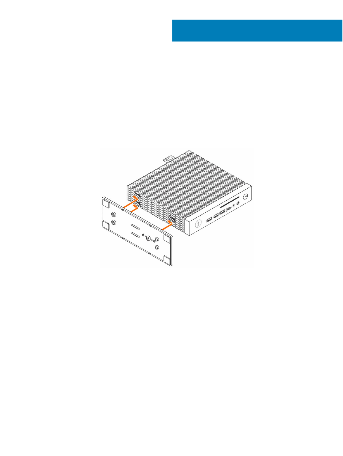
1 Install the stand.
4
Figure 2. Installing the stand
2 Connect the keyboard and mouse.
10 Setting up the thin client
Page 11

Figure 3. Installing keyboard and mouse
3 Connect the network cable.
Figure 4. Installing network cable
4 Connect the display and press the power button.
Setting up the thin client
11
Page 12

Figure 5. Connecting the display
5 Connect the power cable and route the power cable through the cable clip, and press the power button.
Setting up the thin client
12
Page 13

Figure 6. Connect the power cable
Setting up the thin client
13
Page 14

Technical specications
This section provides the technical specications of the Wyse 5070 thin client features.
Topics:
• System specications
• Processor specications
• Operating systems
• Memory
• Storage
• Audio specications
• Communication specications
• Ports and connectors specications
• Security
• Battery specications
• AC adapter specications
• Physical specications
• Environmental specications
5
System specications
This section describes the system specications of the thin client.
Table 1. System
Feature Specication
Chipset Intel Gemini Lake
DRAM bus width 64-bit
Flash EPROM SPI 16 MB
specications
Processor specications
This section describes the processor details of the thin client.
Table 2. Processor
Feature Specications
Type Intel Pentium Silver J5005 (Gemini Lake) Intel Celeron J4105 (Gemini Lake)
Cache 4 MB 4 MB
Graphics EU (Execution Unit) 18 12
specications
Maximum single core burst frequency 2.8 GHz 2.5 GHz
14 Technical specications
Page 15

Feature Specications
Thermal Design Power (TDP) 10 W 10 W
Operating systems
The following operating systems are supported for Wyse 5070 thin client:
• ThinOS
• Windows 10 IoT Enterprise
• ThinLinux
Memory
This section describes the memory specication of the thin client.
Table 3. Memory specications
Feature Specication
Memory connector Two SODIMM slots
Memory capacity 4 GB (1 x 4 GB), 8 GB (2 x 4 GB)
Memory type DDR4 SODIMM
Speed 2133/2400 MHz
Minimum memory 4 GB
Maximum memory 8 GB
Storage
This section describes the storage specications of the thin client.
Table 4. Storage
Interface
Solid-state drive One M.2 2260/2280 slot
Capacity
specications
• One M.2 for SSD—standard
• SATA 6 Gbps
Standard—32 GB to 256 GB
Audio specications
This section describes the audio specications of the thin client.
Table 5. Audio
Feature Specication
Controller Realtek ALC3253 and Intel
Internal interface
specications
• High-denition audio codec
Technical specications 15
Page 16

Feature Specication
• DP audio
External interface
• Headset/mic combo jack at front and rear panels.
• Headphone jack
Communication specications
This section describes the communication specications of the thin client.
Table 6. Communication specications
Feature Specication
Network adapter—onboard 10/100/1000 Mb/s Ethernet—RJ45
Second network adapter (optional) 10/100/1000 Mb/s Ethernet (RJ45) or (100/1000) SFP
Wireless card One M.2 2230 WLAN slot
Antenna
Wireless options
• Dual external antenna connected to the Wireless card
• Frequency (GHz)—2.4 and 5
• Intel Dual Band Wireless-AC 2x2
• USB 2.0 interface for Bluetooth 4.0
Ports and connectors specications
This section provide details about the ports and connectors in the thin client.
Table 7. Ports and connectors
Feature Specication
Audio
Video
Network adapter
USB Front Back
specications
• Two headset/mic combo jacks—Pentium. Rear headset port is present in Pentium
model only.
• One headphone jack—Pentium
• One headset jack—Celeron
• Two DisplayPort v1.2a supports up to two displays, at 4Kx60 Hz
• One DisplayPort v1.2a, without audio—Pentium
• One VGA—optional
• One RJ45 connector
• Second RJ45 or SFP module (ber and 1Gbps copper)—optional
• One USB 2.0 port
• One USB 2.0 port with PowerShare
• One USB Type-C port
• One USB 3.0 port
• One USB 3.0 with Smart Power-on
• Three USB 3.0 ports
16 Technical specications
Page 17

Feature Specication
Common Access Card reader Accepts 1.8 V, 3 V, and 5 V cards
Security
The section provides security options available for Wyse 5070 thin client:
• TPM chip onboard v2.0
• Chassis intrusion detection
• Kensington lock
• Pad lock
Battery specications
The Wyse 5070 thin client supports the following coin-cell battery:
Table 8. Battery specications
Feature Specication
Coin-cell battery 3 V CR2032 lithium coin-cell battery
NOTE:
• Do not ingest the battery, as it will cause chemical burn hazard.
• If the coin / button cell battery is swallowed, it can cause severe internal burns in just two hours, and can lead to death.
• Keep the new and used batteries away from children.
• If the battery compartment does not close securely, stop using the thin client and keep it away from children.
• If the batteries have been swallowed, seek medical attention immediately.
AC adapter
This section describes the power adapter specications of the thin client.
Table 9. AC adapter
Feature Specication
Type 65 W and 90 W
Input voltage 100-240 VAC
Input current (maximum) 1.7 A (65 W)/1.5 A (90 W)
Input frequency 50-60 Hz
Output current 3.34 A (65 W)/4.62 A (90 W)
Rated output voltage 19.5 VDC
specications
specications
Temperature range (Operating) 0 ~ 40° C (32 ~ 104° F)
Temperature range (Non-Operating) -40 ~ 70° C (-40 ~ 158° F)
Technical specications 17
Page 18

Physical specications
This section describes the physical dimensions of the thin client.
Table 10. Physical specications
Feature Specication
Height 18.4 cm (7.24 inches)
Width 3.56 cm (1.4 inches)
Depth 18.4 cm (7.24 inches)
Starting weight 1.13 kg (2.5 lb)
Environmental specications
This section describes the environmental specications of the thin client.
Table 11. Environmental specications
Feature Specication
Temperature
Operating 0° ~ 40° C (32 ~ 104° F)
Storage -40° ~ 70° C (-40° ~ 158° F)
Relative humidity—maximum
Operating 95% non-condensing
Storage 95% non-condensing
Altitude—maximum
Operating 5000 m (16404.2 ft)
Non-operating 10668 m (35000 ft)
Airborne contaminant level Not applicable
18 Technical specications
Page 19

6
Wyse 5070 thin client conguration on ThinOS
This section provides the instructions on how to easily congure and eciently manage Wyse 5070 thin client that runs on ThinOS. .
Topics:
• Introduction
• Logging on to the Wyse 5070 thin client running Wyse ThinOS
• Conguring ThinOS using the First Boot Wizard
• Local settings menu
• Conguring the printer settings
Introduction
Thin clients running Dell Wyse ThinOS rmware are designed solely for optimal thin client security and performance. These ecient
purpose-built thin clients are virus and malware resistant, and oer ultrafast access to applications, les and network resources within
Citrix, Microsoft, VMware and Dell vWorkspace environments, and other leading infrastructures. ThinOS based thin clients are selfmanaged, go from power-on to fully productive in seconds, and with no published API, locally accessible le system or browser, require no
local McAfee Anti-Virus software or rewall to protect against viruses or malware.
Logging on to the Wyse 5070 thin client running Wyse ThinOS
What you see after logging on to the server depends on the administrator congurations.
• Users with a Classic Desktop - will see the classic ThinOS desktop with full taskbar, desktop, and Connect Manager familiar to ThinOS
users. This module oers the default out-of-the-box experience and is recommended for terminal server environments with published
applications and for backward compatibility with ThinOS 6.x versions.
• Users with a Zero Desktop - will see the Zero Desktop with the Zero Toolbar showing the assigned list of connections from which to
select. This option is recommended for VDI and any full-screen– only connections.
In any desktop, you can select the desktop option you want (Classic Desktop or Zero Desktop) and create the connections you need by
using the Visual Experience tab on the Remote Connections dialog box.
To open the Remote Connections dialog box, perform one of the following tasks:
• Classic Desktop — Click User Name , and then select System Setup > Remote Connections.
• Zero Desktop — Click the System Settings icon on the Zero Toolbar, and then select Remote Connections.
NOTE
: User Name is the user who is logged-on and is located at the lower-left pane of the taskbar
Conguring ThinOS using the First Boot Wizard
The First Boot Wizard runs the rst time you start a new thin client with the ThinOS version 8.5. The thin client starts the First Boot
Wizard application before you enter the ThinOS system desktop, and allows you to perform a set of tasks, such as, conguring system
Wyse 5070 thin client conguration on ThinOS 19
Page 20

preferences, setting up the internet connectivity, loading USB congurations, conguring management software, and conguring broker
connections.
If you are an existing thin client user, and you have upgraded to the ThinOS version 8.5, then you can reset your thin client to factory
default settings to enter the First Boot Wizard.
The First Boot Wizard runs the rst time you start a new thin client with the ThinOS version 8.5.1. The thin client starts the First Boot
Wizard application before you enter the ThinOS system desktop, and allows you to perform a set of tasks, such as, conguring system
preferences, setting up the internet connectivity, loading USB congurations, conguring management software, and conguring broker
connections.
You can also reset your thin client to factory default settings to enter the First Boot Wizard.
To congure the First Boot Wizard:
1 Connect a new thin client or existing thin client to the Ethernet using a wired connection. The existing thin client must be reset to
factory default settings to enter the First Boot Wizard.
2 Turn on your thin client.
The thin client checks for a wired network connection. If the network connection is successful, a welcome screen with the model
name of your thin client is displayed.
The thin client validates the IP address from DHCP. If the DHCP contains the le server or the Wyse Device Manager or Wyse
Management Suite congurations, then the ThinOS system desktop is loaded without entering the First Boot Wizard. If the DHCP
validation fails or if you have not connected to Ethernet, then follow the next step.
NOTE
: To exit the First Boot Wizard during the network connection status check on the welcome screen, press the Ctrl +
Esc key.
3 On the Would you like to load a ThinOS conguration le from USB? screen, do either of the following:
• To load a ThinOS conguration le from the USB drive, ensure that you create a wnos.ini le and add the le to the /wnos
directory on the USB drive. Using this option, you can load packages, and wallpapers that are specied in the INI le. Plug in the
USB drive to thin client, and click Yes.
NOTE
: Only FAT, FAT32, and ExFAT le systems on the USB disk are supported. NTFS le system is not
supported.
The thin client validates the conguration le in the USB drive.
– If the ThinOS conguration le in the USB drive is correct, the Read conguration success message is displayed. Click OK to
exit the First Boot Wizard, and log in to the ThinOS system desktop.
– If the ThinOS conguration le in the USB drive is corrupted or the appropriate le is not available, then the Cannot nd
conguration les, or read conguration failure message is displayed. Upload the correct le on the USB drive, plug the USB
drive again, and then click Retry. If the le is correct, the Read conguration success message is displayed. Click OK to exit
the First Boot Wizard, and log in to the ThinOS system desktop.
If you do not want to use the Retry option to load the ThinOS conguration le, then click Abort to enter the System
Preferences conguration setup.
NOTE
: To exit the Cannot nd conguration les, or read conguration failure message screen, and load the
ThinOS system desktop, click Exit.
• To enter the System Preferences conguration setup, click No.
4 On the System Preferences Conguration screen, congure the following options:
• Locale—Select a language to start ThinOS in the regional specic language.
• Keyboard Layout—Select a keyboard layout to set the keyboard layout in the regional specic language.
• Time Zone—Select a time zone to set the time zone for your thin client.
• Time Server—Displays the IP addresses or host names with optional port number of time servers.
• Advanced—Click Advanced to congure settings, such as daylight saving, time format, date format, and time servers.
: To exit the System Preferences Conguration screen, and load the ThinOS system desktop, click
NOTE
Exit.
20 Wyse 5070 thin client conguration on ThinOS
Page 21

If you are not connected to Ethernet, you cannot continue with the setup, and the Attach the Ethernet cable screen is displayed. Do
either of the following:
• Connect the Ethernet cable to the thin client.
• Click Dene a wireless connection. From the list, select a wireless network, and click Connect.
NOTE:
– The option to dene a wireless connection is not available on thin clients without a WLAN module.
– To exit the Attach the Ethernet cable screen, and load the ThinOS system desktop, click Exit.
After the connection is established, the thin client validates the IP address from DHCP. If the DHCP contains the le server or the
Wyse Device Manager or Wyse Management Suite congurations, then the ThinOS system desktop is loaded. If the DHCP validation
fails, or the network connection fails, then the Management Conguration screen is displayed. Follow steps 6–9.
5 Click Next to enter the Management Conguration setup.
6 On the Management Conguration screen, congure the following:
• File Server—Enter the le server details to apply congurations including INI les, rmware, packages, and so on, from a le
server.
• WMS—Enter the group registration key and the Wyse Management Suite server URL to register the thin client to the Wyse
Management Suite.
• WDM—Enter the IP addresses or host names.
• Disable SSL warning—Select this check box to disable the SSL (Secure Sockets Layer) connection warnings.
• Certicates Manager—Click Certicates Manager to import or request a certicate.
NOTE: To exit the Management Conguration screen, and load the ThinOS system desktop, click
Exit.
7 Click Done to exit the First Boot Wizard or click Next to enter the Connection Broker Conguration setup.
8 On the Connection Broker Conguration screen, congure the following:
• Citrix—The broker allows you to connect to full desktops using XenDesktop or individual applications using XenApp from a
centralized host through Citrix Receiver Client.
– Server Address—Enter the host name or IP address of the broker connection.
– Enable theme: ThinOS Lite—Select this check box to boot the thin client in ThinOS Lite mode.
– StoreFront style—Select this check box to enable the Citrix StoreFront based layout of published applications and desktops
on the thin client.
• Microsoft—The broker allows you to connect to the virtual desktops using RemoteApp and Desktop connection. Enter the host
name or IP address of the broker connection.
• VMware—The broker allows you to connect to the remote desktops using VMware Horizon Client.
– Server Address—Enter the host name or IP address of the broker connection.
– Enable theme: VMware View—Select this check box to set the ThinOS desktop theme to VMware View mode.
• DELL—The broker allows you to connect to the virtual desktops or applications using Dell vWorkspace. Enter the host name or IP
address of the broker connection.
• Amazon WorkSpaces—The broker allows your PCoIP clients to connect to virtual desktops that run on AWS. Enter the host
name/IP address/FQDN of the broker connection.
NOTE
: Amazon WorkSpaces option is applicable only to the PCoIP clients.
• Other—The broker allows you to connect to the virtual desktops or applications using other supported protocols. Enter the host
name or IP address of the broker connection.
• Certicates Manager—Click Certicates Manager to import or request a certicate.
• Disable SSL warning—Select this check box to disable the warnings for your SSL (Secure Sockets Layer) connection.
9 Click Done.
: To congure the Management Conguration setup again, click Back, and follow steps 6 and
NOTE
7.
The device exists from the First Boot Wizard mode, and the ThinOS desktop is displayed.
Wyse 5070 thin client
conguration on ThinOS 21
Page 22

Local settings menu
To access the Local settings menu:
• Zero desktop — Click the System Settings icon on the Zero toolbar. Administrators can also click the Admin Mode button on the
Login dialog box.
• Classic desktop — Click User Name, and select System Setup.
NOTE: User Name is the user who is logged-on.
Conguring the keyboard settings
To congure the keyboard settings:
1 From the desktop menu, click System Setup, and then click Peripherals.
The Peripherals dialog box is displayed.
2 Click the Keyboard tab and set the Character Set, Keyboard Layout, Delay Before Repeat and Repeat Rate parameters. The following
table explains the keyboard parameters.
Table 12. Keyboard parameters
Parameter Description
Character Set Lists the character sets. Each character is represented by a
number. The ASCII character set, for example, uses the numbers
0 through 127 to represent all English characters and special
control characters. European ISO character sets are similar to
ASCII, but they contain additional characters for European
languages.
Keyboard Layout Presently the keyboard languages listed in the Keyboard layout
drop-down list are supported. The default value is English
(United States).
Delay Before Repeat Lists the repeat parameters. Select Delay Before Repeat value as
either 1/5 second, 1/4 second, 1/3 second, 1/2 second, 3/4
second, 1 second, 2 seconds, or No Repeat. The default is 1/3
second.
Repeat Rate Select Slow, Normal, or Fast. The default value is Medium.
3 Click OK to save the settings.
Conguring the mouse settings
To congure the mouse settings:
1 From the desktop menu, click System Setup, and then click Peripherals.
The Peripherals dialog box is displayed.
2 Click the Mouse tab, select the mouse speed and mouse orientation.
3 Select the Swap left and right mouse buttons check box to swap mouse buttons for left-handed operations.
4 Click OK to save the settings.
Wyse 5070 thin client conguration on ThinOS
22
Page 23

Conguring the display setup
Use the Display Setup dialog box to congure the display settings for the connected monitors.
To congure the display setup:
1 From the desktop menu, click System Setup, and then click Display.
The Display Setup dialog box is displayed.
2 In the Display Setup dialog box, congure the following options:
• Mirror mode—Select the Mirror mode check box to enable all connected monitors to use the same display settings congured on
the primary monitor.
The following screen represents the Mirror mode conguration.
If you clear the Mirror mode check box, the Span Mode is enabled. The following screen represents the span mode conguration.
Blocks displayed on the screen represent the number of monitor screens connected to thin client. Each block represents a single
monitor screen.
Every monitor contains a unique display order number and display conguration. To construct a new display layout, move the
blocks to your preferred position, and click Apply. A new display layout is created. However, the system sets the block to its default
position if the block is moved to an incorrect position.
NOTE: Wyse 5070 thin client supports up to six monitors.
• Main screen—Select the Main screen check box to set the monitor as primary monitor or main screen. To set a monitor as main
screen, click the monitor block, and select the Main screen check box. After you set the monitor as main screen, the monitor block
is highlighted with an underline, and the Main screen option is disabled for that monitor block. The Main screen option is available
for other monitor blocks.
NOTE
: Main screen option is eective only in Span Mode and always disabled in Mirror Mode.
• Resolution—From the Resolution drop-down list, select a display resolution supported by your monitor.
In Mirror Mode, the resolution list is derived from the intersection of resolutions in all connected monitors.
In Span Mode, select a monitor block and change its resolution from the Resolution drop-down list.
• Rotation—From the Rotation drop-down list, select an option to rotate the monitor screen in dierent directions—Left turn 90
degrees or Right turn 90 degrees. By default, the option is set to None.
3 Click Apply.
The new display settings are applied, and you can see the modied display.
4 Click OK to conrm the new settings.
: Use the Identify option, to know the display order number of the connected monitors.
NOTE
Conguring the LPD settings
1 From the desktop menu, click System Setup, and then click Printer.
The Printer Setup dialog box is displayed.
2 Click the LPDs tab, and use the following guidelines when printing to a non-Windows network printer:
: Be sure to check with your vendor that the printer can accept from Line Printer Request.
NOTE
a Select LPD —Select the required port from the list.
b Printer Name —(Required) Enter the name of the printer that is displayed on the Windows printer driver.
c Printer Identication—Enter the name of the printer exactly as it appears on the Windows printer driver.
In an MS Windows system, this name is either the device driver name of the printer or a key to map the printer to the device
driver. The name will be defaulted to the printer-supplied identication for standard direct-connected USB printers or Generic /
Wyse 5070 thin client
conguration on ThinOS 23
Page 24

Text for non-USB connected printers on connection to Windows hosts. The driver name mapping takes place either through a
printer-mapping le read by the system as part of the global prole (wnos.ini) or by MetaFrame servers through the MetaFrame
printer conguration le (\winnt\system32\wtsprnt.inf).
d LPD Hosts—The DNS or WINS name of the server for the network printer. An IP address of the printer on the network can also
be entered.
If the printer is attached to another thin client on your network, the entry in the LPD Hosts box is the name or address of that
thin client.
e LPD Queue Name — An LPD host maintains a named queue for each supported printer. Enter the name of the queue
associated with the printer to be used.
This name can be dierent for each vendor. This is a required eld, and you must ensure to add the correct queue name, as the
network printer uses this name for mapping the incoming print jobs. For example, auto can be used for HP LaserJet 4200n PCL6
as per documentation found on the HP Web site.
NOTE: If the printer is attached to another thin client on your network, the LPD Queue Name must match the content
of the Printer Name box displayed on the thin client.
f Printer Class — (Optional) Select the printer class from the list.
g Enable the printer device — Select this option to enable the printer on a remote device.
3 Click OK to save the settings.
Conguring the dual head display settings in Dell Wyse ThinOS
To congure the dual head display settings in Wyse ThinOS:
1 From the desktop menu, click System Setup, and then click Display.
2 In the Display dialog box, click Dual Head and do the following. Click the Dual Head tab, and use the following guidelines:
This feature is applicable for supported dual-monitor-capable thin clients only.
a Dual Head—Select Mirror Mode to have the two monitors work, or Span Mode to have the two monitors work individually.
b Main Screen—Select either Screen 1 or Screen 2 as the main screen from (Screen1 or Screen2). The other screen is extended
from the main screen.
c Layout—Select how you want the two monitors to be oriented to each other.
Horizontal — You can navigate between the monitors from the left and right of the screens.
Vertical— You can navigate between the monitors from the top and bottom of the screens.
d Alignment— Select how you want the monitors to be aligned Bottom, Center, or Top.
Screens are bottom-aligned in a horizontal orientation; center-aligned; top-aligned in a horizontal orientation.
e Taskbar (Classic Desktop Only)—Select under which screen you want the taskbar to appear Whole Screen or Main Screen.
NOTE
:
Gamma Supported Monitors Only— Use the Gamma Setup tab to adjust the saturation values for Red, Green and Blue on
VGA connected monitors supporting gamma settings, if you feel the default settings are too light. Be aware that the Gamma
Setup tab will be disabled once you click Save+Exit. You can enable it again by setting rgamma={1-100} ggamma={1-100}
bgamma={1-100} in the Resolution INI parameter. For more information, about enabling the Gamma Setup tab, see Dell Wyse
ThinOS INI Guide.
For Swap dual screens, when you set Main Screen to Screen2, an additional check box is displayed at the bottom of the tab that
allows you to swap dual screens. If you clear the check box, the Screen1 is usually the left one or the top one in dual display.
When you set Main Screen to Screen2, the main screen is changed to the right screen or bottom screen. If you select the Swap
dual screens check box, you are able to set Main Screen to Screen2, but still have it at the left side or the top side.
Wyse 5070 thin client conguration on ThinOS
24
Page 25

Conguring the printer settings
Use the Printer Setup dialog box to congure network printers and local printers that are connected to the thin client. A thin client has
multiple ports that can be used for connecting multiple printers. You can also connect multiple printers to a single port by using a USB hub.
Conguring the ports settings
To congure the ports settings:
1 From the desktop menu, click System Setup, and then click Printer.
The Printer Setup dialog box is displayed.
2 Click the Ports tab, and use the following guidelines:
a Select Port— Select the required port from the list. LPT1 or LPT2 are directly connected to the USB printer..
b Printer Name — (Required) Enter name you want displayed in your list of printers.
Most USB direct-connected printers report/ll in their printer name automatically.
NOTE: If Enable LPD service for the printer is selected, the printer name becomes the queue name for other clients
that are using LPR to print to this printer.
c Printer Identication — Enter the printer name and model in the Windows printer driver name—including capitalization and
spaces, most USB direct-connected printers report/ll in their printer identications automatically.
This entry must be either the device driver name for the printer under the Microsoft Windows system, or a key to map to the
device driver. The printer name is used to identify standard direct-connected USB printers or Generic / Text Only for non-USB
connected printers on Windows hosts. The driver name mapping takes place either through a printer-mapping le read by the
system as part of the global prole (wnos.ini) or by MetaFrame servers through the MetaFrame printer conguration le (\winnt
\system32\wtsprnt.inf).
NOTE
: The maximum characters allowed in the Printer Identication eld is 31. If your printer driver string is more
than 31 characters (including space), you can create a txt le (printer.txt) and upload to your le server. Edit the txt
le and type the content, such as "HP Color" = "HP Color LaserJet CM1312 MFP PCL6 Class Driver".
Add the command line printermap=printer.txt to your wnos.ini le. Now, you can type “HP Color” in the
Printer Identication eld instead of the full driver string.
d Printer Class— This is optional. Select the printer class from the list.
e Enable the printer device — Select this option to enable the directly-connected printer. It enables remote host to display the
device.
f Enable LPD service for the printer — Select this to make the thin client. Write the spelled out for rst, with abbreviation in
parentheses.
NOTE
:
If the thin client is to be used as an LPD printer server, DHCP must not be used and a static IP address must be assigned to
the client.
3 Click OK to save the settings.
Conguring the LPD settings
1 From the desktop menu, click System Setup, and then click Printer.
The Printer Setup dialog box is displayed.
2 Click the LPDs tab, and use the following guidelines when printing to a non-Windows network printer:
: Be sure to check with your vendor that the printer can accept from Line Printer Request.
NOTE
a Select LPD —Select the required port from the list.
Wyse 5070 thin client
conguration on ThinOS 25
Page 26

b Printer Name —(Required) Enter the name of the printer that is displayed on the Windows printer driver.
c Printer Identication—Enter the name of the printer exactly as it appears on the Windows printer driver.
In an MS Windows system, this name is either the device driver name of the printer or a key to map the printer to the device
driver. The name will be defaulted to the printer-supplied identication for standard direct-connected USB printers or Generic /
Text for non-USB connected printers on connection to Windows hosts. The driver name mapping takes place either through a
printer-mapping le read by the system as part of the global prole (wnos.ini) or by MetaFrame servers through the MetaFrame
printer conguration le (\winnt\system32\wtsprnt.inf).
d LPD Hosts—The DNS or WINS name of the server for the network printer. An IP address of the printer on the network can also
be entered.
If the printer is attached to another thin client on your network, the entry in the LPD Hosts box is the name or address of that
thin client.
e LPD Queue Name — An LPD host maintains a named queue for each supported printer. Enter the name of the queue
associated with the printer to be used.
This name can be dierent for each vendor. This is a required eld, and you must ensure to add the correct queue name, as the
network printer uses this name for mapping the incoming print jobs. For example, auto can be used for HP LaserJet 4200n PCL6
as per documentation found on the HP Web site.
NOTE: If the printer is attached to another thin client on your network, the LPD Queue Name must match the content
of the Printer Name box displayed on the thin client.
f Printer Class — (Optional) Select the printer class from the list.
g Enable the printer device — Select this option to enable the printer on a remote device.
3 Click OK to save the settings.
Conguring the SMBs settings
1 From the desktop menu, click System Setup, and then click Printer.
The Printer Setup dialog box is displayed.
2 Click SMBs tab, and use the following guidelines when printing to a Windows network printer.
a Select SMB—Select the SMB you want from the list.
b Printer Name—(Required) Enter the name to be displayed in your list of printers.
c Printer Identication—Enter the type or model of the printer in the exact text of the Windows printer driver name—including
capitalizations and spaces.
This name must be either the device driver name for the printer under the Microsoft Windows system, or a key to map to the
device driver. If not specied, the name will be defaulted to the printer-supplied identication for standard direct-connected USB
printers or Generic / Text for non-USB connected printers upon connection to Windows hosts. The driver name mapping takes
place either through a printer-mapping le read by the system as part of the global prole (wnos.ini) or by MetaFrame servers
through the MetaFrame printer conguration le (\winnt\system32\wtsprnt.inf).
d \\Host\Printer—Enter the Host\Printer or use the browse folder icon next to the box to browse your Microsoft Networks and
make the printer selection you want from the network printers available (the DNS name or IP address of the Windows print
server on the network).
e Printer Class —(Optional) Select the printer class from the list.
f Enable the printer device—Must be selected to enable the printer. It enables the device so it displays on the remote host.
g Enable LPD service for the printer—Select this to make the thin client an LPD (Line Printer Daemon) network print server for
LPR printing requests from the network.
If the thin client is to be used as an LPD printer server, DHCP must not be used and a static IP address must be assigned to the
thin client as described in network settings.
3 Click OK to save the settings.
Wyse 5070 thin client conguration on ThinOS
26
Page 27

Using the printer setup options
To congure the printer setup options:
1 From the desktop menu, click System Setup, and then click Printer.
The Printer Setup dialog box is displayed.
2 Click the Options tab, and do the following:
a Default Printer —From the list of available printers, select the printer that you want to be default printer.
b Enable .print Client and Port —If you want to enable .print Client, select Enable print Client , and then enter the port name.
3 Click OK to save the settings.
Wyse 5070 thin client conguration on ThinOS 27
Page 28

7
Wyse 5070 thin client on ThinLinux
This section provides instructions on how to easily congure and eciently manage Wyse 5070 thin client that runs on ThinLinux.
Topics:
• Introduction
• Logging on to the Wyse 5070 thin client running ThinLinux
• Conguring peripherals settings on Wyse ThinLinux
Introduction
The thin clients running Wyse ThinLinux from Dell simplies the user management paradigm with elegant application icons and comes with
a single built-in user to enhance user experience along with having the benets of a single-operating system. ThinLinux running on thin
client combines the security, exibility, and market-leading usability of enterprise-grade Linux with Dell’s thin computing optimizations in
management. It is ideal for organizations that want to run server-based, Web-based, or local applications including legacy applications
without the deployment and security concerns of a nonstandard Linux distribution.
Logging on to the Wyse 5070 thin client running ThinLinux
On your initial conguration, Dell recommends that you connect by using a wired connection by plugging in the network connected
ethernet cable to your thin client.
After you turn on your thin client, you are automatically logged in to the local thinuser account. By default, the password of the thinuser
account is set to thinuser.
: In cases where a GDM login is needed (for example, AD/Domain login, PNAgent login and so on), the auto-login option
NOTE
can be turned o through the GUI or by using the INI.
Admin mode enables you to perform system administration tasks such as adding or removing connections and setting up specic device
settings. To enter into the Admin mode, click the Switch to Admin button from Setting application screen to admin mode and then enter
the default root password in the Password Needed window. The default root password is admin.
Conguring peripherals settings on Wyse ThinLinux
On the System Settings page, click the Peripherals icon. The following tabs are displayed on the left pane of the System Settings page.
• Keyboard
• Mouse
• Printers
• Sound
Setting the keyboard preferences
The Keyboard setting page enables you to set the Keyboard preferences and make the Keyboard layout.
28 Wyse 5070 thin client on ThinLinux
Page 29

NOTE: By default, the Keyboard screen is available in both User mode and Admin mode. Any changes made through Keyboard
preferences screen is saved and continued for the built-in thinuser
1 Click the ON/OFF button to disable or enable the Key presses repeat when held down option after you log in to the session.
2 Move the slider to the left to decrease the repeated delay time of the pointer or move the slider to the right to increase the repeated
delay time of the pointer.
3 Move the slider to the left to decrease the repeat rate of the pointer or move the slider to the right to increase the repeat rate of the
pointer.
4 In the keyboard layout box, select the layout you want to use and click Add to include the preferred layout in the currently added
layouts list.
5 Select the preferred keyboard layout from the currently added layouts list, and click Set as Default Layout button to set the default
layout.
NOTE: The default keyboard layout is listed on the top of the currently added layout list.
6 Click Save to save your changes.
Customizing the display for Wyse 5070 thin client
By default, the Customize your display screen is available in both user mode and admin mode. Any changes to display preferences are
saved and available for the built-in user named thinuser. In a Dual-monitor conguration, if both monitors are connected, then by default,
the monitors are in extended mode. The primary monitor is on the left (monitor 1), and the secondary monitor is on the right (monitor 2).
The resolutions of the monitors are auto detected by the system by analyzing the monitor capabilities.
To customize the display, do the following:
1 Click the Display tab.
The Customize Your Display page is displayed.
2 From the Resolution drop-down list, select the preferred resolution.
3 From the Rotation drop-down list, select the rotation.
• Normal
• Right
• Left
• Upside-down
4 To switch between dual display and mirror mode in a dual monitor conguration, click the ON/OFF button.
5 To enable the Set as primary option, click the ON/OFF button. This option allows you to set the selected monitor as primary.
6 To enable the monitor On/O option, click the ON/OFF button. This option allows you to turn o and turn on the preferred monitor
in a dual monitor conguration.
Setting the mouse preferences
By default, the Mouse screen is available in both User mode and Admin mode. Any changes made through the Mouse preferences screen is
saved and continued for the built-in thinuser.
The Mouse setting page enables you to set the Mouse preferences.
1 Click Right or Left to set the primary button of the mouse.
2 Move the slider to the left to increase the speed of the pointer when double-clicked or move the slider to the right to decrease the
length of double-clicked.
3 Move the slider to the left to increase the speed of the mouse pointer or move the slider to the right to decrease the speed of the
mouse pointer.
4 Click Save to save your changes.
Wyse 5070 thin client on ThinLinux
29
Page 30

Conguring the printer settings
By default, the Printers screen is available only in Admin mode. On the Printer setting page, click the printer icon to start the gnome-
control-center printer.
1 Click the printer icon.
The gnome-control-center printer dialog box is displayed.
2 Click Add New Printer button to include the new printer in the printers list available on the left pane.
The Add a new printer window is displayed.
3 Enter the address of the printer or the text to lter results.
NOTE: If a USB printer is connected, then it is displayed by default. The printer is not found if wrong address is provided or
the USB is not attached.
4 Click the Add option. Click Print Test Page to test the printer and click (- )icon to remove the printer.
30 Wyse 5070 thin client on ThinLinux
Page 31

8
Wyse 5070 thin client on Windows 10 IoT
Enterprise
This section provides the instructions on how to easily congure and eciently manage Wyse 5070 thin client that runs on Windows 10 IoT
Enterprise.
Topics:
• Introduction
• Setting up Wyse 5070 thin client
• Before conguring your thin clients
• Automatic and manual login
• Keyboard and region settings
• Devices and printers
Introduction
The thin clients running Windows 10 IoT Enterprise provide access to applications, les, and network resources. The applications and les
are made available on machines hosting Citrix Receiver, Microsoft Remote Desktop Connection, VMware Horizon client session, and Dell
Wyse vWorkspace services.
Other locally installed software permits remote administration of the thin clients and provides local maintenance functions. More add-ons
are available that support a wide range of specialty peripherals and features for environments that require a secure user interface with 64bit Windows compatibility. Your thin client device supports Microsoft Silverlight, Microsoft Lync VDI 2013 plug-in, and Microsoft .Net
Framework 4.6 or later versions. For more information, see Microsoft Website
Setting up Wyse 5070 thin client
This section explains how to setup Wyse 5070 thin client on Windows 10 IoT Enterprise.
This section will be lled with OOBE information, and will provide information on how a customer will setup the thin client when the
customer starts using the thin client on Windows 10 IoT Enterprise.
Before conguring your thin clients
Unied Write Filter Utility and NetXClean Utility are meant to protect your thin clients. If you want to retain certain prole congurations
such as printers, monitors and other peripherals, you can congure NetXClean to refrain from cleaning up explicitly declared proles. These
utilities also prevent undesired ash memory writes, and clean-up extraneous information from being stored on the local disk.
However, there are instances where administrators can retain the changed congurations after you log out and restart the thin client.
NOTE
: To congure and manage multiple thin clients, see Dell Cloud Client Computing.
Automatic and manual login
What you see when a thin client turns on or reboots depends on the administrator’s conguration. After creating a user account, an
administrator can congure the account to log in automatically or manually with user credentials. Ensure that you disable the Unied Write
Wyse 5070 thin client on Windows 10 IoT Enterprise 31
Page 32

Filter (UWF) before you change a password on the thin client, and then enable UWF after your change. To change the password, press Ctrl
+Alt+Delete, and then click Change a password. However, this feature is not applicable for User accounts.
CAUTION:
CAUTION: Please follow proper write lter and Windows Page File usage instructions at all times. Such instructions include making
sure that the write lter is enabled during regular use and is disabled only temporarily by an administrator when required for image
upgrades, applying security patches, registry changes and application installation. The write lter should be re-enabled as soon as such
tasks are completed. Such instructions further include never enabling the Windows Page File feature during regular use of the thin
client.
Any operation of a Dell Wyse Windows Embedded Thin Client with the write lter turned o during regular use and/or with the
Windows Page le enabled will prematurely wear out your Flash/SSD storage, decrease performance and decrease the lifespan of the
product.
Dell is not responsible for, and will not, warrant, support, repair or replace any thin client device or component that fails to operate
properly due to a failure to follow these instructions.
When you start the thin client, you will automatically log in to the user desktop by default.
NOTE: The Windows icon on the taskbar is the start menu button.
To log in as a dierent user or administrator:
1 Go to Start > User icon > Sign Out to log out from the current desktop.
2 Click anywhere on the lock screen to view the login window.
3 You can view the user accounts list on the screen. Click the preferred user account and then enter the login credentials.
• Administrators—The default user name is Admin and the default case-sensitive password is DellCCCvdi.
• Users—The default user name is User and default case-sensitive password is DellCCCvdi.
• Customized User—Log in to your thin client by entering the user credentials which you have set for the customized user
account.
If automatic login is not enabled, the login window displays when you boot the thin client device. You can log in using the options mentioned
in step 2 and step 3.
Enabling auto logon
Automatic logon to a user desktop is enabled by default on the thin client device. To enable or disable auto logon, and to change the default
user name, password, and domain for a thin client, use the auto logon feature.
To enable/disable auto logon:
1 Log in as an administrator.
2 Go to Start > Dell Thin Client Application.
The Dell Thin Client Application window is displayed.
3 On the left navigation bar, click Auto Logon.
4 To start with the admin logon page, enter Admin in the Default User Name eld.
: By default, the Enable Auto Logon check box is selected.
NOTE
5 If you want to start with the Logon window with default administrator and user selections and other accounts, clear the Enable Auto
Logon check box.
CAUTION
Before Conguring your thin clients.
32 Wyse 5070 thin client on Windows 10 IoT Enterprise
: To permanently save the information, disable/enable the Unied Write Filter (UWF). For more information, see
Page 33

NOTE:
If auto login is enabled and you log o from your current desktop, the lock screen is displayed. Click anywhere on the lock screen
to view the Logon window. Use this window to log in to your preferred administrator or user account.
Keyboard and region settings
To select your regional formats including keyboard and the Windows display languages, use the Region dialog box.
To select your regional formats, do the following:
1 Log in as an administrator.
2 Go to Start > Control Panel > Region.
The Region dialog box is displayed.
3 In the Formats tab, select the language, date, and time.
To customize the formats, do the following:
a Click Additional Settings.
The Customize Format window is displayed.
b Customize the settings, and click OK.
4 Click Apply, and then click OK.
5 In the Location tab, select a particular location to display additional information such as news and weather.
6 In the Administrative tab, change the language to be displayed in programs that do not support Unicode, and copy the settings.
Devices and printers
To add devices and printers, use the Devices and Printers window.
CAUTION
more information, see Before Conguring your thin clients.
To add a device or a printer to the thin client, do the following:
1 Log in as an administrator.
2 Go to Start > Control Panel > Devices and Printers.
The Devices and Printers window is displayed.
Adding printers
To add a printer to the thin client:
1 Click the Devices and Printers icon in Control Panel.
The Devices and Printers window is displayed.
2 To open and use the Add a Printer wizard, click Add a Printer.
The Add a Printer wizard session starts.
A Dell Open Print Driver is installed on the thin client along with other built-in print drivers. To print full text and graphics to a local
printer, install the driver provided by the manufacturer according to the instructions.
: To refrain from cleaning up your settings, disable/enable the Unied Write Filter (UWF) and congure NetXClean. For
Printing to network printers from Citrix Receiver, Remote Desktop Connection or VMware Horizon Client applications can be
achieved through printer drivers on the servers.
Printing to a local printer from Citrix Receiver, Remote Desktop Connection or VMware Horizon Client application using the printer
drivers of the server produces full text and graphics functionality from the printer. Install the printer driver on the server, and the text
only driver on the thin client using the following procedure:
Wyse 5070 thin client on Windows 10 IoT Enterprise
33
Page 34

a Click Add a local printer, and click Next.
b Click Use an existing port, select the port from the list, and then click Next.
c Select the manufacturer and model of the printer, and click Next.
d Enter a name for the printer and click Next.
e Select Do not share this printer and click Next.
f Select whether to print a test page and click Next.
g Click Finish to complete the installation.
A test page will print after installation if this option was selected.
Conguring dual monitor display
You can use the Screen Resolution window to congure dual monitor settings on your dual-monitor capable thin client device.
To open the Screen Resolution window, do the following:
1 Log in as an administrator.
2 Go to Start > Control Panel > Display > Change Display Settings.
The Screen Resolution window is displayed. For detailed instructions on how to congure the screen resolution, go to
www.microsoft.com.
For information about setting up multiple monitors, see the How to Set up Multiple Monitors in Windows 10 at support.dell.com.
34 Wyse 5070 thin client on Windows 10 IoT Enterprise
Page 35

BIOS overview
Accessing thin client BIOS settings
This section describes about the Wyse 5070 thin client UEFI BIOS settings. While starting a thin client, a Dell logo is displayed for a short
period.
1 During start-up, press the F2 key. and enter the default password Fireport.
The BIOS settings dialog box is displayed.
2 Use the System Setup settings to change the BIOS settings.
NOTE: There is an option to restore BIOS defaults, Factory Defaults, and Custom user settings for Users in the BIOS menu.
BIOS default setting restores the values that was part of the BIOS le. Restoring Factory default restores the BIOS setting
to the values that was congured in factory before shipping the client.
To access the boot menu during start-up, press the F12 key. Use the Boot Selection menu to select or view the boot sequence order as
follows:
• Boot from UEFI: Hard Drive, Partition 4
• Onboard NIC (IPV4)
• Onboard NIC (IPV6)
9
System Setup overview
System Setup allows you to:
• Change the system conguration information after you add, change, or remove any hardware in your thin client.
• Set or change a user-selectable option such as the user password.
• Read the current amount of memory or set the type of hard drive installed.
Before you use System Setup, Dell recommends that you write down the System Setup screen information for future reference.
CAUTION
thin client to work incorrectly.
: Unless you are an expert thin client user, do not change the settings for this program. Certain changes can cause your
Boot Sequence
Boot Sequence allows you to bypass the System Setup–dened boot device order and boot directly to a specic device. During the Poweron Self Test (POST), when the Dell logo appears you can:
• Access System Setup by pressing the F2 key
• Bring up the one-time boot menu by pressing the F12 key
The one-time boot menu displays the devices that you can boot from including the diagnostic option. The boot menu options are:
• UEFI Boot
– UEFI: Hard drive, Partition 4
– Onboard NIC (IPV4)
– Onboard NIC (IPV6)
• Other options
BIOS overview 35
Page 36

– BIOS Setup
– BIOS Flash Update
– Diagnostics
NOTE: If you select the Diagnostics option, the ePSA diagnostics screen is displayed. To access the System setup menu, click
BIOS Setup.
Navigation keys
NOTE: For most of the System Setup options, changes that you make are recorded but do not take eect until you restart the
system.
Table 13. Navigation keys
Keys Navigation
Up arrow Moves to the previous eld.
Down arrow Moves to the next eld.
Enter Selects a value in the selected eld (if applicable) or follow the link in the eld.
Spacebar Expands or collapses a drop‐down list, if applicable.
Tab Moves to the next focus area.
NOTE: This option is applicable for the standard graphics browser only.
Esc Moves to the previous page until you view the main screen. Pressing Esc in the main screen displays a
message that prompts you to save any unsaved changes and restarts the system.
General screen options
This section lists the primary hardware features of your computer.
Table 14. General screen options
Option Description
System Information This section lists the primary hardware features of your computer.
• System Information: Displays BIOS Version, Service Tag, Asset
Tag, Ownership Tag, Ownership Date, Manufacture Date,
Express Service Code, the Signed Firmware update—enabled
by default
• Memory Information: Displays Memory Installed, Memory
Available, Memory Speed, Memory Channels Mode, Memory
Technology, DIMM A Size, DIMM B Size
NOTE: Since Memory Available is less than the
Memory Installed, certain operating systems may not
be able to use all the available memory.
• PCI information: Displays Slot details, by default Slot1 is empty.
• Processor Information: Displays Processor Type, Core Count,
Processor ID, Current Clock Speed, Minimum Clock Speed,
Maximum Clock Speed, Processor L2 Cache, Processor L3
Cache, HT Capable, and 64-Bit Technology
36 BIOS overview
Page 37

Option Description
• Device Information: Primary Hard Drive, EMMC Device, LOM
MAC Address, 2nd NIC MAC Address, Video Controller, Audio
Controller, Wi-Fi Device, Bluetooth Device
Boot Sequence This option enables you to change the order in which the system
boots an operating system.
• Default Boot Sequence
– UEFI: Hard Drive, Partition 4
– Onboard NIC(IPV4)
– Onboard NIC(IPV6)
• Boot List Option: You can add a boot option, delete an existing
boot option, and view the boot options.
UEFI boot path security
Date/Time This option enables you to change the system date and time.
This option enables you to control the system prompt of How to
enter the Admin Password (if set) when you boot a UEFI boot
path from the F12 boot menu.
The options include:
• Always, except internal HDD ( default)
• Always
• Never
System Conguration screen options
Table 15. System
Option Description
UEFI Network Stack If the UEFI Network Stack option is enabled, the UEFI Networking
Integrated NIC The Integrated NIC option controls the on-board LAN controller.
Conguration options
Protocols are installed and allows pre-operating system and early
operating system networking features to use any enabled NICs or
SFP.
The UEFI Network Stack option is enabled by default.
The options include:
• Disabled—The internal LAN is o and not visible to the
operating system.
• Enabled—The internal LAN is enabled.
• Enabled w/PXE—The internal LAN is enabled (with PXE boot).
This option is enabled by default.
2nd NIC (RJ-45/SFP) The second NIC (RJ-45/SFP) option controls the second on-board
NIC. The options include:
• Disabled
• Enabled
• Enabled w/PXE—This option is enabled by default
Parallel Port This option determines how the parallel port on the docking station
operates. The options include:
BIOS overview 37
Page 38

Option Description
• Disabled
• AT—enabled by default
• PS2
• ECP
Serial Port1 This option determines how the serial port on the docking station
operates. It allows you to avoid resource conicts between devices
by disabling or remapping the address. The options include:
• Disabled
• COM1—enabled by default
• COM2
SATA Operation This option congures the operating mode of the integrated SATA
hard drive controller. The options include:
• Disabled
• AHCI—enabled by default
Drives Allows you to congure the SATA drives on board.
• SATA-0 enabled by default
SMART Reporting This eld controls whether the hard drive errors of integrated drives
are reported during system startup.
USB Conguration
Front USB Conguration This option enables or disables front USB ports. The options
This is an optional feature.
This eld congures the integrated USB controller. If Boot Support
is enabled, the system is allowed to boot any type of USB Mass
Storage Devices such as hard drives and USB keys.
If the USB port is enabled, the device attached to this port is
enabled and available for the operating system.
If the USB port is disabled, the operating system cannot detect any
device attached to this port.
The options include:
• Enable USB Boot Support—enabled by default
• Enable Front USB Ports—enabled by default
• Enable Rear USB Ports—enabled by default
NOTE: USB keyboard and mouse always work in the BIOS
setup irrespective of these settings.
include:
• Front port Top—enabled by default
• Front port Bottom Medium—enabled by default
• Front port Top Medium—enabled by default
• Front port Bottom—enabled by default
Rear USB Conguration This option enables or disables rear USB ports. The options are:
• Rear port Top Left—enabled by default
• Rear port Bottom Left—enabled by default
38 BIOS overview
Page 39

Option Description
• Rear port Top Right—enabled by default
• Rear port Bottom Right—enabled by default
USB PowerShare This option congures the USB PowerShare feature and allows you
to charge external devices through the USB PowerShare port when
system is o. This option is enabled by default.
Audio This option enables or disables the integrated audio controller. By
default, the Enable Audio option is selected. The options include:
• Enable Microphone—enabled by default
• Enable Internal Speaker—enabled by default
Video screen option
Table 16. Video screen option
Option Description
Primary Display This option determines which video controller is the primary display
when multiple controllers are available in the system. The options
include:
• Auto—enabled by default
• Intel HD Graphics
Security screen options
Table 17. Security screen options
Option Description
Admin Password This option enables you to set, change, or delete the administrator
password.
NOTE:
• You must set the administrator password before you set
the system or hard drive password. Also, deleting the
administrator password automatically deletes the system
password and the hard drive password.
• Successful password changes take eect immediately.
By default, the administrator password is not set.
System Password This option enables you to set, change, or delete the system
password.
NOTE: Successful password changes take eect
immediately.
By default, the administrator password is not set.
Strong Password This option enables you to enforce the option to always set strong
passwords.
By default, the Enable Strong Password option is not selected.
BIOS overview 39
Page 40

Option Description
NOTE: If Strong Password is enabled, the administrator
and system passwords must contain at least one
uppercase character and one lowercase character. The
password must be at least eight characters long.
Password Conguration This option enables you to specify the minimum and maximum
password lengths of the administrator and system passwords.
• min-4—By default, the minimum value is set to 4. You can
increase the value.
• max-32—By default, the maximum value is set to 32. You can
decrease the value.
Password Bypass This option enables you to enable and disable the permission to
bypass the system and the internal hard drive password, when they
are set. The options are:
• Disabled—enabled by default
• Reboot Bypass
Password Change This option enables you to enable the disable permission to the
system and hard drive passwords when the administrator password
is set.
By default, the Allow Non-Admin Password Changes option is
selected.
UEFI Capsule Firmware Updates This option enables you to enable or disable UEFI Capsule
Firmware. This option controls whether this system enables BIOS
update through UEFI capsule update packages. This option is
enabled by default.
TPM 2.0 Security This option enables you to enable the Trusted Platform Module
Technology feature. The options include:
• TPM On—enabled by default
• Clear
• PPI Bypass for Enable Commands
• Attestation Enable—enabled by default
• PPI Bypass for Disable Commands
• Key Storage Enable—enabled by default
• PPI Bypass for Clear Command
• SHA-256—enabled by default
• Disabled
• Enabled—selected by default
Chassis Intrusion This option enables you to controls the chassis intrusion feature.
The options include:
• Clear Intrusion Warning
• Disabled—enabled by default
• Enabled
• On-Silent
Admin Setup Lockout This option enables you to prevent users from entering Setup when
an administrator password is set.
40 BIOS overview
Page 41

Option Description
SMM Security Mitigation This option enables you to enable and disable additional UEFI SMM
security mitigation protections.
Secure Boot screen options
Table 18. Secure Boot screen options
Options Description
Secure Boot Enable This option enables or disables the secure boot feature. By default,
the Secure Boot Enable option is not set.
Secure Boot Mode This option enables you to change the secure boot operation mode,
modies the behavior of secure boot to allow evaluation or
enforcement of the UEFI driver signatures. The options include:
• Deployed Mode
• Audit Mode
Expert Key Management This option enables you to manipulate the security key databases
only if the system is in Custom Mode. The Enable Custom Mode
option is disabled by default. The options include:
• PK
• KEK
• db
• dbx
If you enable the Custom Mode, the relevant options for PK, KEK,
db, and dbx is displayed. The options are:
• Save to File—Saves the key to a user-selected le
• Replace from File—Replaces the current key with a key from a
user-selected le
• Append from File—Adds a key to the current database from a
user-selected le
• Delete—Deletes the selected key
• Reset All Keys—To reset the default setting
• Delete All Keys—Deletes all the keys
NOTE: If you disable the Custom Mode, all the changes
are erased and the keys are restored to the default
settings.
Performance screen options
Table 19. Performance options
Option Description
Multi Core Support This option species whether one or more cores are enabled on the
processor. The options include:
• All—enabled by default
• 1
• 2
BIOS overview 41
Page 42

Option Description
• 3
Intel SpeedStep This option enables you to enables or disables the Intel SpeedStep
feature. The option is:
Enable Intel SpeedStep
This option is enabled by default.
C-States Control This option enables you to enables or disables the additional
processor sleep states.
This option is disabled by default.
Intel TurboBoost This option enables you to enables or disables the Intel TurboBoost
mode of the processor. The option is:
Enable Intel TurboBoost—This option is enabled by default.
Power management screen options
Table 20. Power management options
Option Description
AC Recovery This option enables you to control the system’s behavior when AC
power is restored after a AC power loss.
• Power O—enabled by default
• Power On
• Last Power State
Auto On Time This option enables you to set the time at which the computer
must turn on automatically. The options include:
• Disabled—enabled by default
• Every Day
• Weekdays
• Select Days
Deep Sleep Control This option enables you to determine on how aggressive the system
is at conserving power while shutdown—S5 or in Hibernate (S4)
mode. The options include:
• Disabled—This option enabled by default
• Enabled in S5 only
• Enabled in S4 and S5
Fan Control Override This option enables you to determine the speed of the system fan.
By default, the Fan Control Override option is disabled.
USB Wake Support This option enables USB devices to wake the system from standby.
42 BIOS overview
Page 43

Option Description
NOTE: This feature is only functional when the AC power
adapter is connected. If the AC power adapter is removed
during standby, the system setup removes power from all
the USB ports to conserve battery power.
The Enable USB Wake Support option is enabled by default.
Wake on LAN This option enables or disables the feature that powers on the
computer from the O state when triggered by a LAN signal. The
options include:
• Disabled
• LAN Only—This option is enabled by default.
• LAN with PXE Boot
Wake on 2nd NIC (RJ-45/SFP) This option enables the computer to power up from the OFF state
when triggered by special LAN signals. The options include:
• Disabled—This option is enabled by default.
• LAN Only
• LAN with PXE Boot
Block Sleep The Block Sleep option blocks you from entering to sleep mode in
the operating system environment.
Block Sleep—This option is disabled by default.
POST behavior screen options
Table 21. POST behavior options
Option Description
Adapter Warnings This option enables or disables the system setup (BIOS) warning
messages when you use certain power adapters.
By default, the Enable Adapter Warnings option is enabled.
Keypad Error This option enables you to specify whether keyboard related errors
are reported when the system boots. By default, the Enable
Keyboard Error Detection option is enabled
Numlock LED This option enables and disables the Numlock LED when the
system boots.
By default, this option is enabled.
Fastboot This option enables you to speed up the boot process by bypassing
some of the compatibility steps. The options include:
• Minimal
• Thorough—This option is enabled by default.
• Auto
Extended BIOS POST Time This option enables you to create an extra preboot delay. The
options include:
• 0 seconds—This option is enabled by default.
BIOS overview 43
Page 44

Option Description
• 5 seconds
• 10 seconds
Full Screen Logo This option enables or disables the full screen logo. By default, the
Enable Full Screen Logo option is not enabled.
Wireless screen option
Table 22. Wireless option
Option Description
Wireless Device Enable This options enables or disables the internal wireless devices. The
options include:
• WLAN/WiGig — enabled by default
• Bluetooth—enabled by default
Virtualization support screen options
Table 23. Virtualization options
Option Description
Virtualization This option enables or disables the Intel Virtualization Technology.
Enable Intel Virtualization Technology (default).
VT for Direct I/O This option species whether a virtual machine monitor can utilize
the additional hardware capabilities provided by Intel Virtualization
Technology for Direct I/O. This option is not enabled by default.
Maintenance screen options
Table 24. Maintenance options
Option Description
Service Tag Displays the Service Tag of your computer.
Asset Tag This option enables you to create a system asset tag if an asset tag
is not already set. This option is not set by default.
SERR Messages This option enables you to control the SERR message mechanism.
The Enable SERR Message option is enabled by default.
BIOS Downgrade This controls ashing of the system rmware to previous revisions.
The option Allow BIOS downgrade is enabled by default.
Data Wipe This eld enables you to erase the data securely from all internal
storage devices. Option Wipe on Next boot is not enabled by
default. The following is the list of devices aected:
• Internal SATA HDD/SSD
• Internal M.2 SATA SDD
44 BIOS overview
Page 45

Option Description
• Internal M.2 PCIe SSD
• Internal eMMC
CAUTION: All the information will be lost if you enable this
option.
BIOS Recovery This option enables you to recover certain corrupted BIOS
conditions from a recover le on the user’s primary hard drive or an
external USB key.
• BIOS Recovery from Hard Drive—enabled by default
• BIOS Auto-Recovery—disabled by default
First Power On Date This option enables you to set the ownership date. The Set
Ownership Date option is not set by default.
System Logs screen option
Table 25. System Logs screen option
Option Description
BIOS Events This option enables you to delete all the logs.
BIOS overview 45
Page 46

Troubleshooting your system
You can troubleshoot your system using indicators like diagnostic lights, and error messages during the operation of the device.
Topics:
• Power state and LED status
• Power behavior
• Power LED error code behavior
Power state and LED status
Table 26. Power states and LED behavior
Indicator Symptoms Description
Solid white Thin client is in working—S0 state.
Breathing white Thin client is in sleep—S3 state.
10
Power LED
NOTE: Press and hold the power button for at least 4 seconds to shut down the thin client forcibly.
O Thin client is in o state.
Solid amber Thin client booting is in progress.
Blinking amber Bad power supply.
Power behavior
Table 27. Power behavior
AC adapter System behavior POST error message
AC adapter power is greater than or equal to
the system power requirement at full CPU
speed.
AC adapter Power is less than the system
power requirements at full CPU speed.
AC adapter is not genuine Dell. Limit the CPU speed to the lowest possible
System boots normally and allows CPU to
run at full speed.
Lower the maximum CPU speed to a value
that does not exceed the power available by
the AC adapter.
value.
None
Alert—xxxxxxW AC power adapter has
been detected, which is less than the
recommended xxxxxxW AC adapter
originally shipped. The system adjusts the
performance to match the power available.
Connect a Dell xxxxxxW AC adapter or
greater for best system performance.
Alert—xxxxxxW AC power adapter has
been detected, which is less than the
recommended xxxxxxW AC adapter
originally shipped. The system adjusts the
performance to match the power available.
46 Troubleshooting your system
Page 47

AC adapter System behavior POST error message
Connect a Dell xxxxxxW AC adapter or
greater for best system performance.
AC adapter power is less than power state
of CPU.
No boot or error message, but the system
shuts down.
If the system is able to boot:
Alert—xxxxxxW AC power adapter has
been detected, which is less than the
recommended xxxxxxW AC adapter
originally shipped. The system is unable to
boot. Please connect a Dell xxxxxxW AC
adapter or greater for best system
performance. Press any key to shut down.
Power LED error code behavior
Table 28. Power LED error code behavior
LED# of ashes Fault description Fault Action Comment
2,1 CPU CPU Failure Type A
2,2 Motherboard: BIOS
ROM failure
2,3 Memory No Memory/RAM
2,4 Memory Memory/RAM failure Type A Supported. Memory is
Motherboard, covers BIOS
corruption or ROM error
detected
NA Not applicable to X7 BIOS.
No Test Case support.
NA Not supported. Memory is
solder down on
Motherboard. It is dicult
to validate this function.
solder down on
Motherboard, the Service
team could replace the
motherboard/memory to
repurpose the board for
repair.
2,5 Memory Invalid memory is installed NA Memory is solder down on
motherboard.
2,6 Motherboard:
Chipset
2,7 LCD LCD failure NA This code is not supported.
3,1 RTC Power failure CMOS battery failure Type B
3,2 PCI / Video PCI or Video card/ Chip
3,3 BIOS Recovery 1 Recovery Image not found Type A
3,4 BIOS Recovery 2 Recovery Image found but
4,1 CPU Cong or CPU
Failure
4,2 Generic POST Video
Error—Old LED
pattern 1110
Example: LED# of ashes: 2,1 indicates that LED blinks two times, pauses, and then blinks once.
Troubleshooting action
Motherboard / Chipset
error
failure
invalid
NA This code is not supported.
HW dependent.
There is no LCD.
NA Not applicable to X7 BIOS.
No test case support.
Type A
NA This code is not supported.
NA Not applicable to X7 BIOS.
No test case support.
Troubleshooting your system
47
Page 48

• Type A
– Log the fault event.
– Emit the LED error code pattern.
– Repeat the LED error code pattern in a dead-loop.
• Type B
– Log the fault event, if possible.
– Emit the LED error code pattern.
– Repeat the LED error code 3 more times.
– Leave the LED light up in amber color.
– Continue with POST.
48 Troubleshooting your system
 Loading...