

Dell Studio 540, dddwmb4_4, Studio 540n Setup Manual

SETUP GUIDE


Model DCMA
SETUP GUIDE

Notes, Notices, and Cautions
NOTE: A NOTE indicates important information that helps you make better use of your
computer.
NOTICE: A NOTICE indicates either potential damage to hardware or loss of data and tells you
how to avoid the problem.
CAUTION: A CAUTION indicates a potential for property damage, personal injury, or death.
If you purchased a Dell™ n Series computer, any references in this document to Microsoft® Windows® operating systems
are not applicable.
__________________
Information in this document is subject to change without notice.
© 2008–2009 Dell Inc. All rights reserved.
Reproduction of these materials in any manner whatsoever without the written permission of Dell Inc. is strictly forbidden.
Trademarks used in this text:
Dell
, the
DELL
logo, YOURS IS HERE, and
DellConnect
are trademarks of Dell Inc.;
Intel
,
Pentium
, and
Celeron
are registered trademarks and
Core
is a trademark of Intel Corporation in the U.S. and other
countries;
Microsoft, Windows, Windows Vista,
and
Windows Vista
start button logo are either trademarks or registered
trademarks of Microsoft Corporation in the United States and/or other countries;
Blu-ray Disc
is a trademark of the
Blu‑ray Disc Association;
Bluetooth
is a registered trademark owned by Bluetooth SIG, Inc. and is used by Dell under
license;
Realtek
is a trademark of Realtek Semiconductor Corporation.
Other trademarks and trade names may be used in this document to refer to either the entities claiming the marks and
names or their products. Dell Inc. disclaims any proprietary interest in trademarks and trade names other than its own.
June 2009 P/N W447F Rev. A01

3
Setting Up Your Studio 540 . . . . . . . . . . . . . .5
Before Setting Up Your Computer . . . . . . . . . 5
Connect the Display . . . . . . . . . . . . . . . . . . . . 6
Connect the Keyboard and Mouse. . . . . . . . . 8
Connect the Network Cable (Optional) . . . . . 9
Connect the Power Cables for Your
Display and Computer . . . . . . . . . . . . . . . . . . 10
Press the Power Buttons on Your
Computer and Display . . . . . . . . . . . . . . . . . . 10
Windows Vista Setup . . . . . . . . . . . . . . . . . . 11
Connect to the Internet (Optional) . . . . . . . . 11
Using Your Studio 540 . . . . . . . . . . . . . . . . .14
Front View Features. . . . . . . . . . . . . . . . . . . . 14
Back View Features. . . . . . . . . . . . . . . . . . . . 17
Back Panel Connectors. . . . . . . . . . . . . . . . . 18
Software Features . . . . . . . . . . . . . . . . . . . . . 20
Solving Problems . . . . . . . . . . . . . . . . . . . . .22
Network Problems . . . . . . . . . . . . . . . . . . . . . 22
Power Problems. . . . . . . . . . . . . . . . . . . . . . . 23
Memory Problems . . . . . . . . . . . . . . . . . . . . . 25
Lockups and Software Problems . . . . . . . . . 26
Using Support Tools . . . . . . . . . . . . . . . . . . .28
Dell Support Center . . . . . . . . . . . . . . . . . . . . 28
System Messages . . . . . . . . . . . . . . . . . . . . . 29
Hardware Troubleshooter . . . . . . . . . . . . . . . 30
Dell Diagnostics . . . . . . . . . . . . . . . . . . . . . . 31
System Recovery Options . . . . . . . . . . . . . .33
System Restore . . . . . . . . . . . . . . . . . . . . . . . 33
Dell Factory Image Restore . . . . . . . . . . . . .34
Operating System Reinstallation . . . . . . . . . 36
Contents

4
Contents
Getting Help . . . . . . . . . . . . . . . . . . . . . . . . .38
Technical Support and Customer
Service . . . . . . . . . . . . . . . . . . . . . . . . . . . . . . 39
DellConnect™ . . . . . . . . . . . . . . . . . . . . . . . . .39
Online Services . . . . . . . . . . . . . . . . . . . . . . . 39
Product Information. . . . . . . . . . . . . . . . . . . . 40
Returning Items for Repair Under
Warranty or for Credit . . . . . . . . . . . . . . . . . . 41
Before You Call. . . . . . . . . . . . . . . . . . . . . . . . 42
Contacting Dell. . . . . . . . . . . . . . . . . . . . . . . . 43
Finding More Information and
Resources . . . . . . . . . . . . . . . . . . . . . . . . . . .44
Specifications . . . . . . . . . . . . . . . . . . . . . . .46
Appendix. . . . . . . . . . . . . . . . . . . . . . . . . . . .53
Macrovision Product Notice. . . . . . . . . . . . . 53
Index . . . . . . . . . . . . . . . . . . . . . . . . . . . . . . .54
5
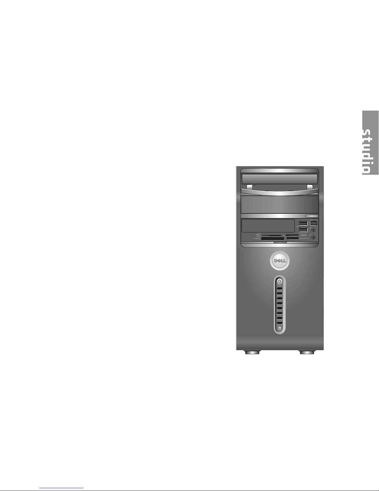
Setting Up Your Studio 540
This section provides information about setting
up your Studio 540 and connecting peripherals.
Before Setting Up Your Computer
When positioning your computer, ensure that
you allow easy access to a power source,
adequate ventilation, and a level surface to
place your computer.
Restricting airflow around your Studio 540 may
cause it to overheat. To prevent overheating
ensure that you leave at least 10.2 cm (4 inches)
at the back of the computer and a minimum of
5.1 cm (2 inches) on all other sides. You should
never place your computer in an enclosed
space, such as a cabinet or drawer when it is
powered on.
6
Setting Up Your Studio 540
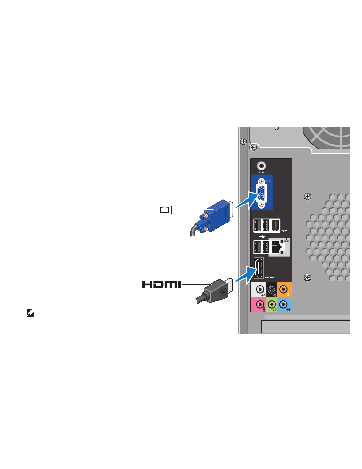
Connect the Display
Your computer uses one of two
different connectors for connecting
the display. The HDMI connector is a
high‑performance digital connector
that carries both video and audio
signals for displays such as TVs and
monitors with integrated speakers.
The VGA connector carries only video
signals for displays such as monitors
and projectors.
NOTE: A DVI connector may be available on
your computer if you purchased an optional
discreet graphics card.
‑OR‑
7
Setting Up Your Studio 540
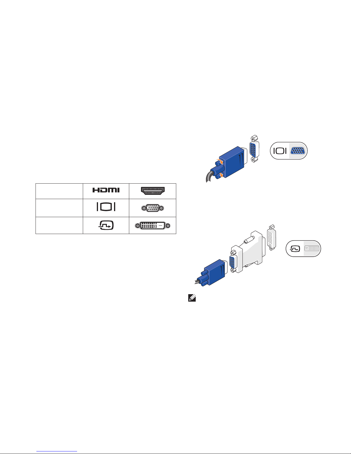
Connect the Video Cable to the Display
Check your TV or monitor to see which type of
connectors are available. Refer to the following
table when identifying the connectors on your
display to select the connection type you
will use.
HDMI
VGA
DVI
You can connect to the display using the
following connectors available on your
computer: the VGA connector, the HDMI
connector, or the DVI connector (optional).
Connect Using the VGA Connector
Connect the display using a VGA cable (which
usually has blue connectors at both ends).
If your computer has a DVI connector, use the
VGA cable (with blue connectors at both ends)
with a DVI‑to‑VGA adapter (white connector).
NOTE: You can purchase a DVI‑to‑VGA
adapter from the Dell website at dell.com.
8
Setting Up Your Studio 540
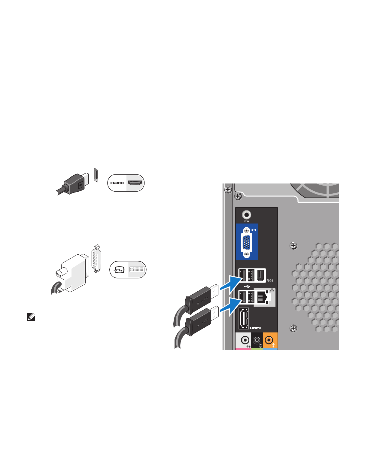
Connect Using the HDMI Connector
Connect the display using an HDMI cable.
Connect Using the DVI Connector (Optional)
Connect the display using a DVI cable.
NOTE: You can purchase additional HDMI
and DVI cables from the Dell website at
dell.com.
Connect the Keyboard and Mouse
Use the USB connectors on the back panel of
the computer to attach a USB keyboard and
mouse.

9
Setting Up Your Studio 540
Connect the Network Cable
(Optional)
A network connection is not required to
complete your computer setup, but if you have
an existing network or Internet connection
that uses a cable connection (such as a
home cable modem or Ethernet jack), you can
connect it now. Use only an Ethernet cable
(RJ45 connector). Do not plug a telephone cable
(RJ11 connector) into the network connector.
To attach your computer to a network or
broadband device, connect one end of the
network cable to either a network port or a
broadband device. Connect the other end of the
network cable to the network adapter connector
on the back panel of your computer. A click
indicates that the network cable has been
securely attached.
10
Setting Up Your Studio 540
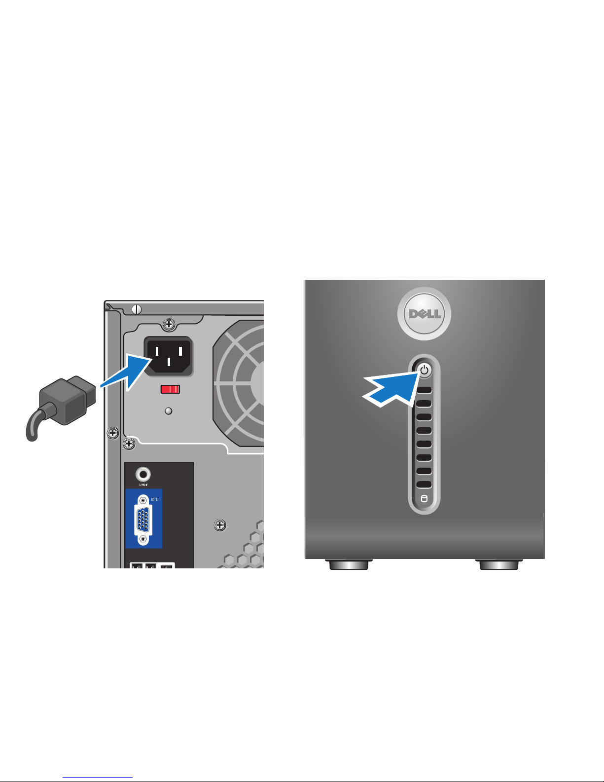
Connect the Power Cables for
Your Display and Computer
Press the Power Buttons on Your
Computer and Display

11
Setting Up Your Studio 540
Windows Vista Setup
To set up Windows Vista® for the first time
follow the instructions on the screen. These
steps are mandatory and may take up to
15 minutes to complete. The screens will take
you through several procedures including
accepting license agreements, setting
preferences, and setting up an Internet
connection.
NOTICE: Do not interrupt the operating
system’s setup process. Doing so may
render your computer unusable.
Connect to the Internet (Optional)
NOTE: ISPs and ISP offerings vary by
country.
To connect to the Internet, you need an external
modem or network connection and an Internet
service provider (ISP). Your ISP will offer one
or more of the following Internet connection
options:
DSL connections that provide high‑speed •
Internet access through your existing
telephone line or cellular telephone service.
With a DSL connection, you can access the
Internet and use your telephone on the same
line simultaneously.
Cable modem connections that provide •
high‑speed Internet access through your
local cable TV line.
Satellite modem connections that provide •
high‑speed Internet access through a
satellite television system.
Dial‑• up connections that provide Internet
access through a telephone line. Dial‑up
connections are considerably slower
than DSL and cable (or satellite) modem
connections. Your computer does not have
an integrated modem. An optional USB
modem must be used for dialup service with
this computer.

12
Setting Up Your Studio 540
Wireless LAN (WLAN) • connections that
provide Internet access using WiFi 802.11
technology. Wireless LAN support requires
optional internal components that may or
may not be installed in your computer based
on decisions made at the time of purchase.
NOTE: If an external USB modem or
WLAN adapter is not part of your original
order, you can purchase one from the Dell
website at dell.com.
Setting Up a Wired Connection
If you are using a dial‑up connection, connect
the telephone line to the external USB modem
(optional) and to the telephone wall jack before
you set up your Internet connection. If you
are using a DSL or cable/satellite modem
connection, contact your ISP or cellular
telephone service for setup instructions.
Setting Up a Wireless Connection
Before you can use your wireless Internet
connection, you need to connect to your
wireless router. To set up your connection to a
wireless router:
Save and close any open files, and exit any 1.
open programs.
Click 2. Start → Connect To.
Follow the instructions on the screen to 3.
complete the setup.
Setting Up Your Internet Connection
To set up an Internet connection with a provided
ISP desktop shortcut:
Save and close any open files, and exit any 1.
open programs.
Double‑click the ISP icon on the Microsoft2.
®
Windows® desktop.
Follow the instructions on the screen to 3.
complete the setup.

13
Setting Up Your Studio 540
If you do not have an ISP icon on your desktop
or if you want to set up an Internet connection
with a different ISP, perform the steps in the
following section.
NOTE: If you cannot connect to the Internet
but have successfully connected in the
past, the ISP might have a service outage.
Contact your ISP to check the service
status, or try connecting again later.
NOTE: Have your ISP information ready. If
you do not have an ISP, the Connect to the
Internet wizard can help you get one.
Save and close any open files, and exit any 1.
open programs.
Click 2. Start → Control Panel.
Under 3. Network and Internet, click Connect
to the Internet.
The Connect to the Internet window appears.
Click either 4. Broadband (PPPoE) or Dial-up,
depending on how you want to connect:
Choose a. Broadband if you will use a
DSL, satellite modem, cable TV modem,
or Bluetooth® wireless technology
connection.
Chose b. Dial-up if you will use an optional
USB dial‑up modem or ISDN.
NOTE: If you do not know which type of
connection to select, click Help me choose
or contact your ISP.
Follow the instructions on the screen and 5.
use the setup information provided by your
ISP to complete the setup.
14
Your computer has indicators, buttons, and
features that provide information at‑a‑glance and
time‑saving shortcuts for common tasks.
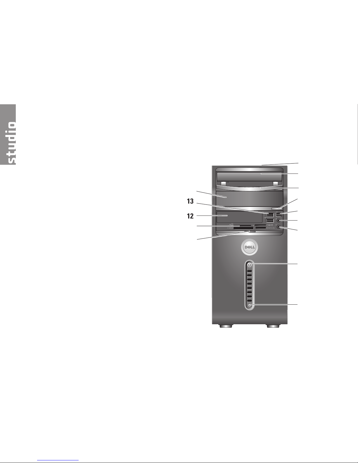
Front View Features
1 Service Tag (located on top of the
chassis towards the back) — Use the
Service Tag to identify your computer
when you access the Dell Support
website or call technical support.
2
Optical drive — Plays or records only
standard‑size (12 cm) CDs, DVDs, and
Blu‑ray Disc™.
3
Optical drive panel — This panel covers
the optical drive (shown in open position).
Using Your Studio 540
1
2
3
4
5
6
7
8
9
12
13
14
10
11
15
Using Your Studio 540
4
Optical drive eject button — Press to
eject a disc from the optical drive.
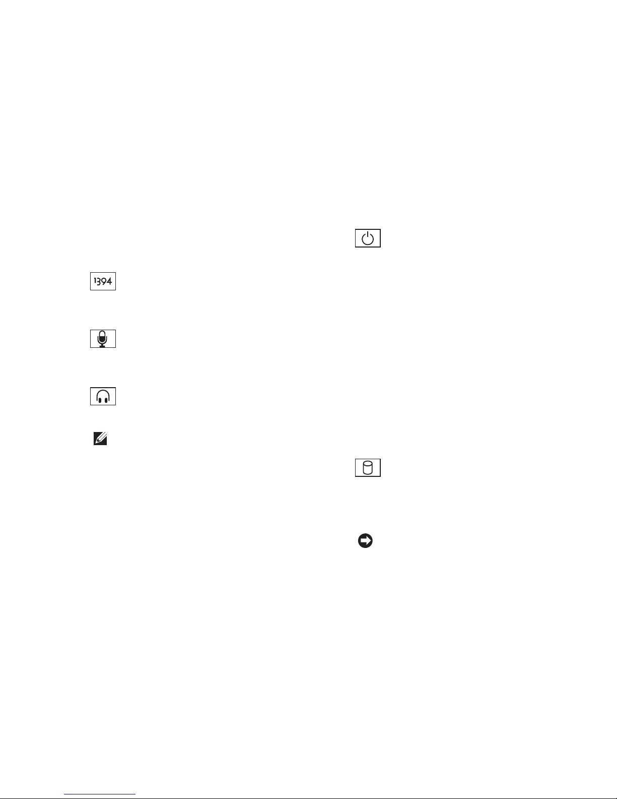
5
IEEE 1394 connector — Connects
to high‑speed serial multimedia devices
such as digital video cameras.
6
Line-in or microphone connector —
Connects to a microphone for voice or to
an audio cable for audio input.
7
Headphone connector — Connects
to headphones.
NOTE: To connect to a powered
speaker or sound system, use the
audio out or S/PDIF connector on the
back of your computer.
8
Power button and light — Turns the
power on or off when pressed. The light
in the center of this button indicates the
power state:
Blinking white — the computer is in •
sleep state.
Solid white — the computer is in •
power‑on state.
Blinking amber — there may be a •
problem with the system board.
Solid amber — there may be a •
problem with either the system board
or power supply.
9
Hard drive activity light — Turns on
when the computer reads or writes data.
A blinking blue light indicates hard drive
activity.
NOTICE: To avoid loss of data, never
turn off the computer while the hard
drive activity light is blinking.

16
Using Your Studio 540
10
Front-panel door grip — Slide up the front
panel door grip to cover the FlexBay drive,
USB connectors, IEEE 1394 connector,
headphone connector, and microphone
connector.
11
Media card reader — Provides a
fast and convenient way to view and
share digital photos, music, videos, and
documents stored on the following digital
memory cards:
Secure Digital (• SD) memory card
•Secure Digital High Capacity (SDHC)
card
Multi • Media Card (MMC)
Memory • Stick
Memory Stick PRO•
xD‑• Picture Card (type ‑ M and type ‑ H)
12
FlexBay drive — Can contain an optional
FlexBay.
13
USB 2.0 connectors (2) — Connects
USB devices that are connected
occasionally such as memory keys,
digital cameras, and MP3 players.
14
Optional Optical drive bay — Can contain
an additional optical drive.
17
Using Your Studio 540
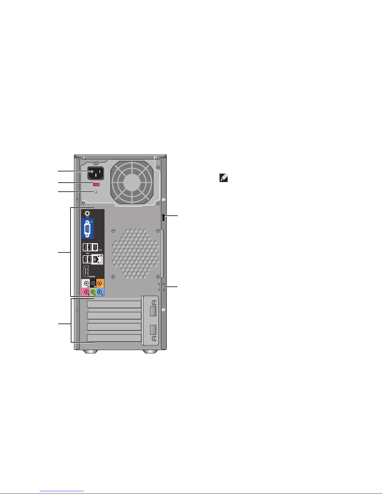
Back View Features
7
1
2
3
4
5
6
1
Security cable slot — Connects to a lock
for a security cable used as an anti‑theft
device.
NOTE: Before you buy a lock, ensure
that it works with the security cable
slot on your computer.
2
Padlock rings — Attach a commercially
available anti‑theft device.
3
Expansion card slots (4) — Access
connectors for any installed PCI and PCI
Express cards.
4
Back panel connectors — Plug USB,
audio, and other devices into the
appropriate connector.
5
Power supply light — Indicates power
availability for power supply.
6
Voltage selector switch — Select the
region specific voltage range.
7
Power connector — Connects your
computer to the power socket.
 Loading...