

Dell DD6300, DD6800, DD9300 Hardware Overview And Installation Manual

Dell EMC Data Domain DD6300, DD6800,
and DD9300 Systems
Version 6.1
Hardware Overview and Installation Guide
302-003-008
REV 08

Copyright © 2016-2018 Dell Inc. and its subsidiaries. All rights reserved.
Published May 2018
Dell believes the information in this publication is accurate as of its publication date. The information is subject to change without notice.
THE INFORMATION IN THIS PUBLICATION IS PROVIDED “AS-IS.“ DELL MAKES NO REPRESENTATIONS OR WARRANTIES OF ANY KIND
WITH RESPECT TO THE INFORMATION IN THIS PUBLICATION, AND SPECIFICALLY DISCLAIMS IMPLIED WARRANTIES OF
MERCHANTABILITY OR FITNESS FOR A PARTICULAR PURPOSE. USE, COPYING, AND DISTRIBUTION OF ANY DELL SOFTWARE DESCRIBED
IN THIS PUBLICATION REQUIRES AN APPLICABLE SOFTWARE LICENSE.
Dell, EMC, and other trademarks are trademarks of Dell Inc. or its subsidiaries. Other trademarks may be the property of their respective owners.
Published in the USA.
Dell EMC
Hopkinton, Massachusetts 01748-9103
1-508-435-1000 In North America 1-866-464-7381
www.DellEMC.com
2 Data Domain DD6300, DD6800, and DD9300 Systems 6.1 Hardware Overview and Installation Guide

CONTENTS
Figures
Tables
Chapter 1
Chapter 2
5
7
Revision history 9
Planning and Site Preparation 11
Tools and supplies needed...........................................................................12
Safety information...................................................................................... 12
Field-installed systems vs. factory-racked systems.................................... 13
Data Domain DD6300, DD6800, and DD9300 Hardware Overview
15
Front panel..................................................................................................16
DD6300 front panel........................................................................16
DD6800 front panel........................................................................16
DD9300 front panel........................................................................17
Front LED indicators...................................................................... 18
Back panel...................................................................................................19
DD6300 rear SSDs......................................................................... 19
Rear LED indicators........................................................................19
I/O modules...................................................................................22
Storage capacity........................................................................................ 26
DD6300 storage capacity.............................................................. 26
DD6800 storage capacity.............................................................. 26
DD9300 storage capacity.............................................................. 27
DD6300 system features............................................................................28
DD6300 system specifications................................................................... 29
Internal system components.......................................................................30
DIMMs overview............................................................................30
DD6800 system features............................................................................ 31
DD6800 system specifications................................................................... 32
Internal system components.......................................................................33
DIMMs overview............................................................................33
DD9300 system features............................................................................ 34
DD9300 system specifications................................................................... 35
Internal system components.......................................................................36
DIMMs overview............................................................................36
Chapter 3
Data Domain DD6300, DD6800, and DD9300 Systems 6.1 Hardware Overview and Installation Guide 3
Install the System in the Rack 39
Unpack the system.....................................................................................40
Rails and cable management assembly....................................................... 40
Identify the rack location to install the system............................................ 41
Install the rails............................................................................................. 41
Install the DD6300, DD6800, or DD9300 system into a rack...................... 43
Installing the cable management assembly (CMA)..................................... 45

CONTENTS
Installing the expansion shelves into the racks............................................46
Chapter 4
Chapter 5
Connect Cables and Power on 49
Connecting ES30 shelves...........................................................................50
DD6300..........................................................................................51
DD6800 and DD9300 (single node, DD Cloud Tier, or ERSO)........52
DD6800 and DD9300 (HA or HA with DD Cloud Tier)....................54
Connecting DS60 shelves...........................................................................57
DD6300......................................................................................... 58
DD6800 and DD9300.................................................................... 59
DD6800 and DD9300 with HA........................................................61
DD6800 with DD Cloud Tier...........................................................62
DD6800 and with HA and DD Cloud Tier........................................64
DD9300 with DD Cloud Tier or HA and DD Cloud Tier................... 65
DD6800 and DD9300 with ERSO...................................................67
Connecting the HA interconnect................................................................ 69
Installing the front bezel............................................................................. 70
Connect data cables................................................................................... 70
Power on all systems...................................................................................71
Configure System for Use 73
Enable administrative communication.........................................................74
Accepting the End User License Agreement (EULA).................................. 75
Run the configuration wizard......................................................................75
Configuring the network................................................................ 75
Configuring additional system parameters..................................... 77
Configure HA..............................................................................................78
4 Data Domain DD6300, DD6800, and DD9300 Systems 6.1 Hardware Overview and Installation Guide

FIGURES
1
2
3
4
5
6
7
8
9
10
11
12
13
14
15
16
17
18
19
Warning about lifting the system.................................................................................13
Front LED indicators................................................................................................... 18
Rear LED indicators.................................................................................................... 19
I/O module Power/Service LED location.....................................................................21
Onboard network port LEDs....................................................................................... 22
I/O module slot numbering......................................................................................... 22
CPU and memory locations........................................................................................ 30
CPU and memory locations.........................................................................................33
CPU and memory locations........................................................................................ 36
Warning about lifting the system................................................................................ 40
Cable management assembly (CMA).......................................................................... 41
Warning about lifting the system................................................................................ 43
Service tag (components removed for clarity)........................................................... 45
Installing the CMA on the rack....................................................................................45
Adjusting the CMA depth........................................................................................... 46
DD6300 with ES30 shelves........................................................................................ 52
DD6800 and DD9300 with ES30s, single node, DD Cloud Tier, or ER.........................54
DD6800 and DD9300 with ES30s and HA or HA with DD Cloud Tier.......................... 56
HA interconnect......................................................................................................... 70
Data Domain DD6300, DD6800, and DD9300 Systems 6.1 Hardware Overview and Installation Guide 5

FIGURES
6 Data Domain DD6300, DD6800, and DD9300 Systems 6.1 Hardware Overview and Installation Guide

TABLES
1
2
3
4
5
6
7
8
9
10
11
12
13
14
15
16
17
18
19
20
21
22
23
24
25
26
27
28
29
30
31
32
33
34
35
36
37
38
39
40
41
42
43
44
45
46
47
48
Document revision history............................................................................................ 9
DD6300 AIO capacity..................................................................................................16
DD6300 AIO configuration.......................................................................................... 16
DD6300 AIO expanded configuration.......................................................................... 16
DD6800 DLH SSD requirements..................................................................................17
DD6800 DLH configuration drive layout...................................................................... 17
DD6800 DLH expanded configuration drive layout...................................................... 17
DD9300 DLH SSD requirements..................................................................................17
DD9300 DLH configuration drive layout...................................................................... 17
DD9300 DLH expanded configuration drive layout...................................................... 17
Front LEDs.................................................................................................................. 18
DD6300 I/O slot module mapping...............................................................................23
DD6800 and DD9300 I/O module slot mapping.......................................................... 23
I/O module slot population rules................................................................................. 24
DD6300 storage capacity........................................................................................... 26
DD6800 storage capacity........................................................................................... 27
DD9300 storage capacity........................................................................................... 27
DD6300 system features............................................................................................ 28
DD6300 system specifications................................................................................... 29
System operating environment...................................................................................29
DD6300 memory DIMM configuration........................................................................ 30
Memory locations - CPU 0......................................................................................... 30
Memory locations - CPU 1...........................................................................................31
DD6800 system features.............................................................................................31
DD6800 system specifications................................................................................... 32
System operating environment...................................................................................32
DD6800 memory DIMM configuration........................................................................ 33
Memory locations - CPU 0......................................................................................... 33
Memory locations - CPU 1.......................................................................................... 34
DD9300 system features............................................................................................ 34
DD9300 system specifications................................................................................... 35
System operating environment...................................................................................35
DD9300 memory DIMM configuration........................................................................ 36
Memory locations - CPU 0......................................................................................... 36
Memory locations - CPU 1.......................................................................................... 37
Cables for primary node to ES30 shelf loop................................................................50
Cables for standby node to ES30 shelf loop............................................................... 50
ES30 to ES30 cable options........................................................................................51
Primary node cabling instructions...............................................................................55
Standby node cabling instructions..............................................................................55
DS60 cables............................................................................................................... 57
Primary node cabling instructions............................................................................... 61
Standby node cabling instructions...............................................................................61
Primary node cabling instructions...............................................................................64
Standby node cabling instructions.............................................................................. 64
Primary node cabling instructions...............................................................................65
Standby node cabling instructions..............................................................................66
Communications settings............................................................................................74
Data Domain DD6300, DD6800, and DD9300 Systems 6.1 Hardware Overview and Installation Guide 7

TABLES
8 Data Domain DD6300, DD6800, and DD9300 Systems 6.1 Hardware Overview and Installation Guide

Revision history
Table 1 Document revision history
Revision Date Document part # Software version Description
08 May 2018 302-003-008 6.1 Added references
07 January 2018 302-003-008 6.1 Added rack
06 June 2017 302-003-008 6.1 Editorial revisions.
to documentation
for systems
shipped in a rack
from the factory.
dimensions,
corrected power
specifications,
and editorial
revisions.
05 April 2017 302-003-008 6.0 Editorial revisions.
04 January 2017 302-003-008 6.0 Added heat
dissipation
(BTU/hr) to the
system
specifications.
03 December 2016 302-003-008 6.0 Editorial revisions.
02 October 2016 302-003-008 6.0 Editorial revisions.
01 October 2016 302-003-008 6.0 Initial publication.
Revision history 9

Revision history
10 Data Domain DD6300, DD6800, and DD9300 Systems 6.1 Hardware Overview and Installation Guide

CHAPTER 1
Planning and Site Preparation
l
Tools and supplies needed.................................................................................. 12
l
Safety information..............................................................................................12
l
Field-installed systems vs. factory-racked systems............................................ 13
Planning and Site Preparation 11

CAUTION
Planning and Site Preparation
Tools and supplies needed
These tools and supplies may be helpful for the installation and setup tasks for Data
Domain systems.
l
Null modem cable (DB-9 female to female), plus spare
l
USB-to-DB-9 serial (male connector) converter cable if the laptop does not have a
serial port, plus spare
l
Power adapter, C13 to NEMA 5–15 (if based in North America), or a power cord
for your laptop power adapter with a C13 plug, so that you can power your laptop
from a rack PDU
l
Antistatic wrist strap and conductive foam pad
l
Screwdrivers:
n
Phillips #2 with a 12 in. or longer blade
n
Phillips #2 (standard-length blade)
n
Phillips #1
n
Flat head 3/16 in.
n
Flat head 1/4 in.
n
Torx T10
l
Flashlight
l
Needle nose pliers
l
Diagonal wire cutters (for cutting tie wraps)
l
2 GB or greater USB flash memory drive
l
Tie wraps (4 in. and 8 in.)
l
(recommended) Roll of 5/8 inch Velcro cable tie material (3M Scotchmate
SJ-3401 or similar)
Safety information
12 Data Domain DD6300, DD6800, and DD9300 Systems 6.1 Hardware Overview and Installation Guide
l
If the system is used in a manner that is not specified by the manufacturer,
the protection that is provided by the equipment may be impaired.
l
The RJ45 sockets on the motherboard, PCI cards, or I/O modules are for
Ethernet connection only and must not be connected to a
telecommunications network.
Review this list of important safety recommendations.
l
All plug-in modules and blank plates are part of the fire enclosure and must be
removed only when a replacement can be added immediately. The system must
not be run without all parts in place.
l
DD6300, DD6800, and DD9300 systems must be operated only from a power
supply input voltage range of 100–240 VAC and 50–60 Hz. The ES30 and FS15
CAUTION
Planning and Site Preparation
shelves use 100–240 VAC and 50–60 Hz. DS60 shelves use 200–240 VAC and
50–60 Hz.
l
Each component is intended to operate with all working power supplies installed.
l
Provide a suitable power source with electrical overload protection.
l
A safe electrical earth connection must be provided to each power cord. Check
the grounding of the power sources before applying power.
l
The plug on each power supply cord is used as the main device to disconnect
power from the system. Ensure that the socket outlets are located near the
equipment and are easily accessible.
l
Permanently unplug the unit if you think it is damaged in any way and before
moving the system. DD6300, DD6800, and DD9300 systems include two power
supplies. To remove system power completely, disconnect both power supplies.
l
The power connections must always be disconnected before removal or
replacement of a power supply module from the system.
l
A faulty power supply module must be replaced within 24 hours.
l
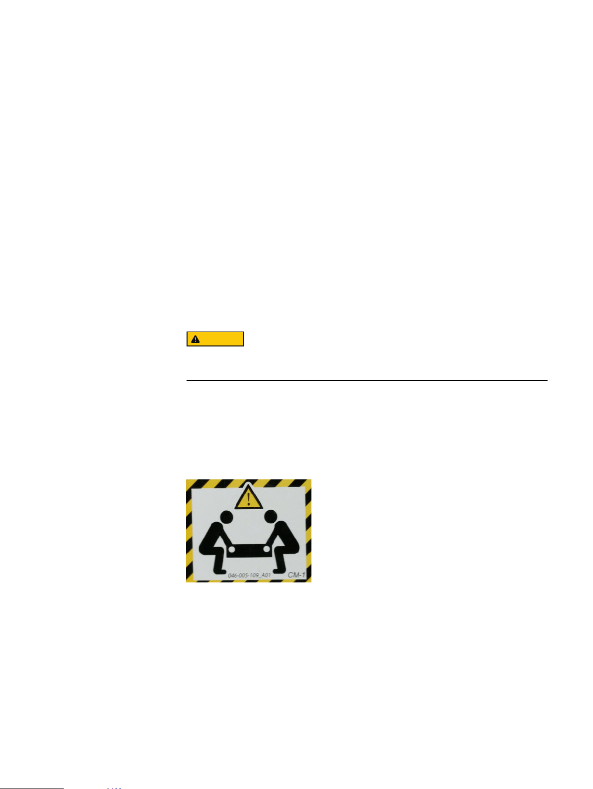
Do not lift system components by yourself. DD6300, DD6800, and DD9300
systems weigh up to 80 lbs (36.29 kg) and an ES30 expansion shelf weighs up to
68 lbs (30.8 kg). A DS60 shelf weighs up to 225 lbs (102 KG)
Data Domain systems are heavy. Use at least two people or a mechanical lift
to move any system.
l
Do not lift an expansion shelf by the front handles on any modules. The handles are
not designed to support the weight of the populated shelf.
l
To comply with applicable safety, emission, and thermal requirements, covers
must not be removed and all bays must be fitted with plug-in modules.
l
Once removed from the shipping box, it is ok to lift the system or the chassis
Figure 1
l
To prevent the rack from becoming top-heavy, load the rack with storage shelves
Warning about lifting the system
beginning at the bottom and the system in the designated location.
l
Data Domain recommends that you wear a suitable antistatic wrist or ankle strap
for ESD protection. Observe all conventional ESD precautions when handling plugin modules and components.
Field-installed systems vs. factory-racked systems
Data Domain systems are available from the factory as components to install in an
existing rack on site, or pre-installed in a rack. The following sections provide
additional information about each type of installation.
Field-installed systems vs. factory-racked systems 13

Planning and Site Preparation
Field-installed systems
This installation guide is primarily intended for systems shipped as components to be
installed in an existing rack on site. Follow all the instructions in this document to rack,
cable, and configure the system.
Factory-racked systems
Factory-racked systems are pre-installed in the rack, with the cables already
connected. Follow the instructions in the chapter
Configure System For Use
to
configure the factory-racked system.
The following documents, available from the Online Support website at https://
support.emc.com, provide additional information about the factory rack:
l
Dell EMC 40U-P Cabinet Site Preparation Guide
l
Dell EMC 40U-P Cabinet Unpacking and Setup Guide
l
Data Domain Rack Service Guide
14 Data Domain DD6300, DD6800, and DD9300 Systems 6.1 Hardware Overview and Installation Guide

CHAPTER 2
Data Domain DD6300, DD6800, and DD9300 Hardware Overview
l
Front panel......................................................................................................... 16
l
Back panel.......................................................................................................... 19
l
Storage capacity................................................................................................26
l
DD6300 system features................................................................................... 28
l
DD6300 system specifications...........................................................................29
l
Internal system components.............................................................................. 30
l
DD6800 system features.................................................................................... 31
l
DD6800 system specifications...........................................................................32
l
Internal system components.............................................................................. 33
l
DD9300 system features....................................................................................34
l
DD9300 system specifications...........................................................................35
l
Internal system components.............................................................................. 36
Data Domain DD6300, DD6800, and DD9300 Hardware Overview
15
Note
Note
Data Domain DD6300, DD6800, and DD9300 Hardware Overview
Front panel
The front panel contains 12 slots for a mix of 4 TB hard disk drives (HDDs) and 800 GB
solid state drives (SSDs). The exact layout of the drives, and the types of drives used
varies depending on the specific system model.
Configurations that do not fill all 12 drive slots use filler panels in the empty slots to
maintain proper air flow inside the chassis.
DD6300 front panel
DD6300 All-in-One (AIO) systems have one of the following front panel drive
configurations to host the DD OS boot drives, and provide storage for customer data:
Upgrading a base configuration to an expanded configuration provides less capacity
than a factory-built expanded configuration.
Table 2 DD6300 AIO capacity
Configuration Installed drives Usable internal
capacity
DD6300 base
configuration
DD6300 expanded
configuration (factory)
DD6300 expanded
configuration (upgrade)
Table 3 DD6300 AIO configuration
Slot 0: HDD 1 Slot 1: HDD 2 Slot 2: HDD 3 Slot 3: HDD 4
Slot 4: HDD 5 Slot 5: HDD 6 Slot 6: HDD 7 Slot 7: Filler
Slot 8: Filler Slot 9: Filler Slot 10: Filler Slot 11: Filler
Table 4 DD6300 AIO expanded configuration
Slot 0: HDD 1 Slot 1: HDD 2 Slot 2: HDD 3 Slot 3: HDD 4
Slot 4: HDD 5 Slot 5: HDD 6 Slot 6: HDD 7 Slot 7: HDD 8
Seven 4 TB HDDs 14 TB
Twelve 4 TB HDDs 34 TB
Seven 4 TB HDDs + Five 4 TB HDDs 22 TB
Slot 8: HDD 9 Slot 9: HDD 10 Slot 10: HDD 11 Slot 11: HDD 12
DD6800 front panel
DD6800 Dataless Head (DLH) systems have one of the following front panel drive
configurations to host the DD OS boot drives and provide metadata caching on SSD:
16 Data Domain DD6300, DD6800, and DD9300 Systems 6.1 Hardware Overview and Installation Guide
Note
Note
Data Domain DD6300, DD6800, and DD9300 Hardware Overview
Table 5 DD6800 DLH SSD requirements
Configuration Number of SSDs
DD6800 2
DD6800 expanded 4
SSDs are not RAID-protected.
Table 6 DD6800 DLH configuration drive layout
Slot 0: HDD 1 Slot 1: HDD 2 Slot 2: HDD 3 Slot 3: HDD 4
Slot 4: SSD 1 Slot 5: SSD 2 Slot 6: Filler Slot 7: Filler
Slot 8: Filler Slot 9: Filler Slot 10: Filler Slot 11: Filler
Table 7 DD6800 DLH expanded configuration drive layout
DD9300 front panel
Slot 0: HDD 1 Slot 1: HDD 2 Slot 2: HDD 3 Slot 3: HDD 4
Slot 4: SSD 1 Slot 5: SSD 2 Slot 6: SSD 3 Slot 7: SSD 4
Slot 8: Filler Slot 9: Filler Slot 10: Filler Slot 11: Filler
DD9300 Dataless Head (DLH) systems have one of the following front panel drive
configurations to host the DD OS boot drives and provide metadata caching on SSD:
Table 8
DD9300 DLH SSD requirements
Configuration Number of SSDs
DD9300 5
DD9300 expanded 8
SSDs are not RAID-protected.
Table 9 DD9300 DLH configuration drive layout
Slot 0: HDD 1 Slot 1: HDD 2 Slot 2: HDD 3 Slot 3: HDD 4
Slot 4: SSD 1 Slot 5: SSD 2 Slot 6: SSD 3 Slot 7: SSD 4
Slot 8: SSD 5 Slot 9: Filler Slot 10: Filler Slot 11: Filler
Table 10 DD9300 DLH expanded configuration drive layout
Slot 0: HDD 1 Slot 1: HDD 2 Slot 2: HDD 3 Slot 3: HDD 4
DD9300 front panel 17
Data Domain DD6300, DD6800, and DD9300 Hardware Overview
Table 10 DD9300 DLH expanded configuration drive layout (continued)
Slot 4: SSD 1 Slot 5: SSD 2 Slot 6: SSD 3 Slot 7: SSD 4
Slot 8: SSD 5 Slot 9: SSD 6 Slot 10: SSD 7 Slot 11: SSD 8
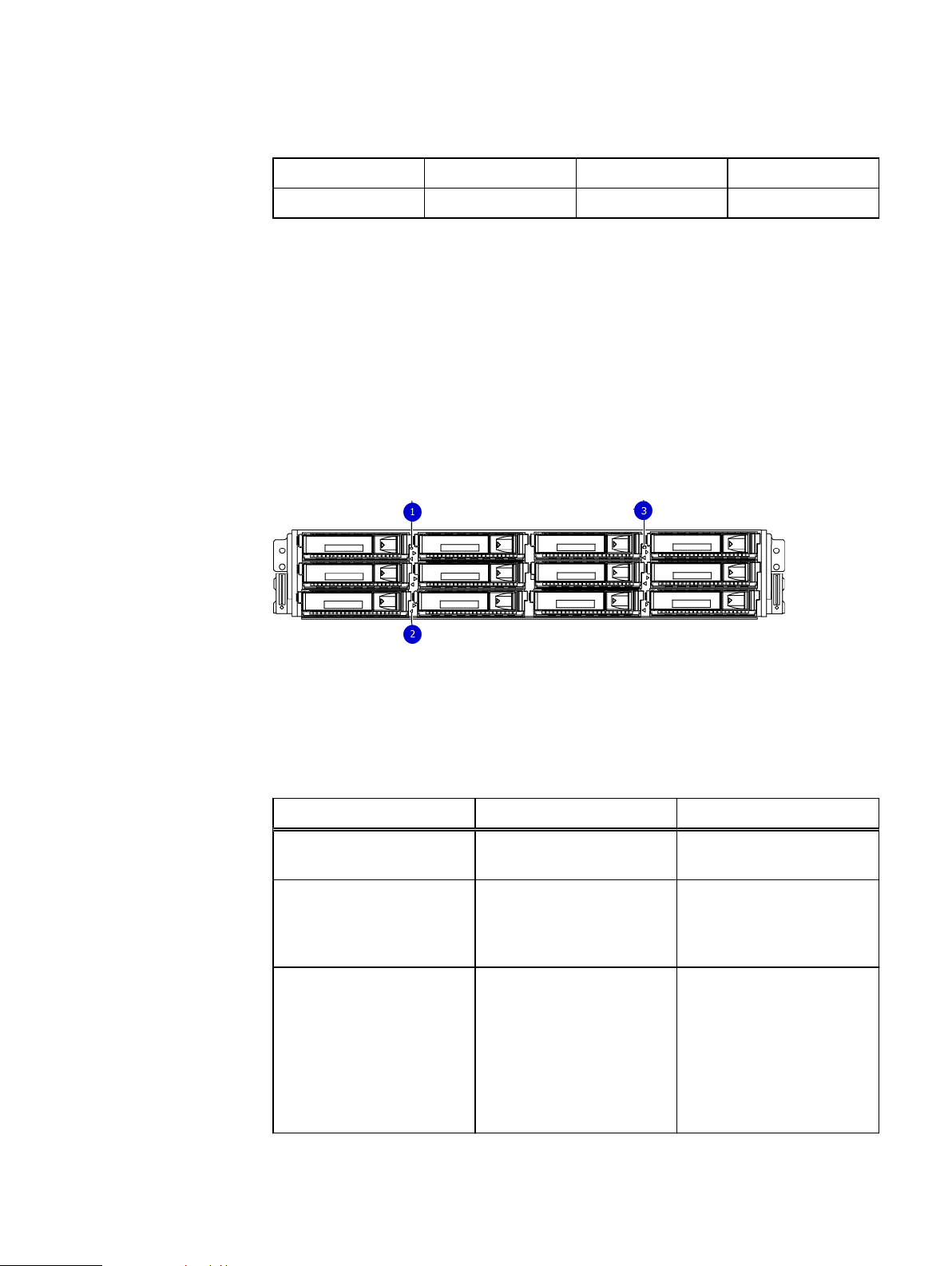
Front LED indicators
The front of the DD6300, DD6800, and DD9300 systems contain 12 disk drive status
LEDs that are normally blue, and blink when there is activity on the disk. The LEDs are
shaped like triangles, and the apex of the triangle points left or right, indicating that
disk's status. If the disk drive has a failure, the disk’s status LED turns from blue to
amber, indicating that a drive must be replaced.
The front also contains two system status LEDs. A blue system power LED is present
that is on whenever the system has power. An amber system fault LED is also present
that is normally off and lit amber whenever the chassis or any other FRU in the system
requires service.
Figure 2 Front LED indicators
1. System service LED
2. Drive activity/service LED
3. System power LED
Table 11
Front LEDs
Name Color Purpose
System power LED Blue Indication that the system has
power.
System service LED Amber Normally off; is lit amber
whenever the SP or any other
FRU (except disk drives) in
the system requires service.
Drive activity/Service LED Blue /Amber
l
Lit blue when the drive is
powered.
l
Blinks blue during drive
activity.
l
Lit solid amber when a
disk needs service.
18 Data Domain DD6300, DD6800, and DD9300 Systems 6.1 Hardware Overview and Installation Guide
Back panel
Note
Data Domain DD6300, DD6800, and DD9300 Hardware Overview
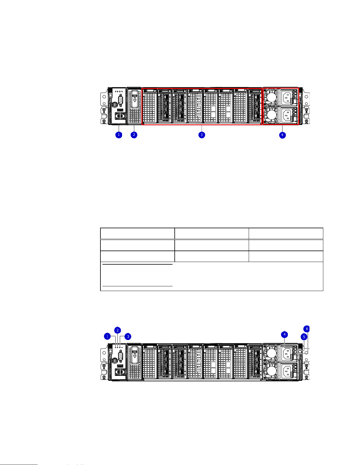
The back panel of the DD6300/DD6800/DD9300 chassis contains the following
components:
1. Management panel
2. Two 2.5" SSD slots labeled 0 and 1 (populated on DD6300 only)
3. I/O module slots
4. Power supply modules (PSU 0 is the lower module, and PSU 1 is the upper
module)
DD6300 rear SSDs
Rear LED indicators
The D6300 system uses one or two 800 GB SSDs mounted at the rear of the chassis
for metadata caching:
Configuration
DD6300 1 SSD slot 0
DD6300 expanded 2 SSD slots 0 and 1
SSDs are not RAID-protected.
Figure 3
Rear LED indicators
Number of SSDs SSD location
1. Do not remove LED
2. SP service LED
3. System power LED
4. AC power good LED
5. DC power good LED
Back panel 19

Data Domain DD6300, DD6800, and DD9300 Hardware Overview
Figure 3 Rear LED indicators (continued)
6. Power supply fault LED
Name of LED Location Color Definition
"Do not remove" LED Upper left-most part
of rear chassis
SP service LED To the right of "Do
not remove" LED
White This LED is lit during
system BIOS and
BMC firmware
updates and indicates
that the SP should
not be removed from
the chassis, nor
should system power
be removed.
Amber
l
Solid amber - SP
or a FRU inside
the SP requires
service
l
Blinking amber blink rate reflects
one of the
following is
booting
n
BIOS - 1/4 Hz
n
POST - 1 Hz
n
OS - 4 Hz
Drive Power/Activity
a
LED
Drive Fault LED
a
Left LED on the SSD Blue Lit blue when the
Right LED on the SSD Amber Lit solid amber when a
System power LED Right-most LED on
the management
panel
PSU FRU LED - AC
Good
PSU FRU LED - DC
Good
PSU FRU LED Attention
a.
The SSD is only present on DD6300 systems.
Top LED on power
supply
Middle LED on power
supply
Bottom LED on power
supply
drive is powered.
Blinks during drive
activity.
drive needs service.
Blue SP has good, stable
power
Green AC input is as
expected
Green DC output is as
expected
Amber PSU has encountered
a fault condition
20 Data Domain DD6300, DD6800, and DD9300 Systems 6.1 Hardware Overview and Installation Guide
Data Domain DD6300, DD6800, and DD9300 Hardware Overview
Figure 4 I/O module Power/Service LED location
1. I/O module power/service LED
Name of LED Location Color Definition
I/O module FRU LED
- Figure 4 on page 21
I/O port status LED
(SAS, Fibre Channel,
and optical
networking I/O
modules only)
a.
For RJ45 networking ports, the standard green link and amber activity LEDs are used.
Ejector handle of I/O
modules
One LED per I/O
module port
Green/Amber
l
Green - I/O
module has power
and is functioning
normally
l
Amber - I/O
module has
encountered a
fault condition
and requires
service
Blue Lit when port is
enabled. May flash if
SW "marks" the
a
port.
Rear LED indicators 21
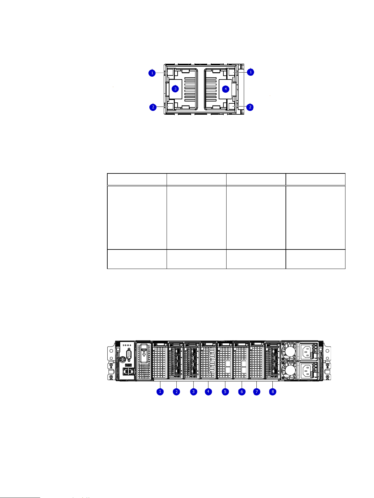
Data Domain DD6300, DD6800, and DD9300 Hardware Overview
Figure 5 Onboard network port LEDs
1. Network port link LED
2. Network port activity LED
3. Dedicated IPMI port BMC0A
4. Management interface EthMa
Name of LED Location Color Definition
I/O modules
Onboard network port
LED - Link LED Figure
5 on page 22
Onboard network port
LED - Activity LED
Top LED on network
port
Bottom LED on
network port
Green
Amber Blinks when there is
l
Lit when there is
a link at
1000BaseT and
100BaseT speeds
l
Off when the link
speed is 10BaseT
or there is no link
traffic on the port
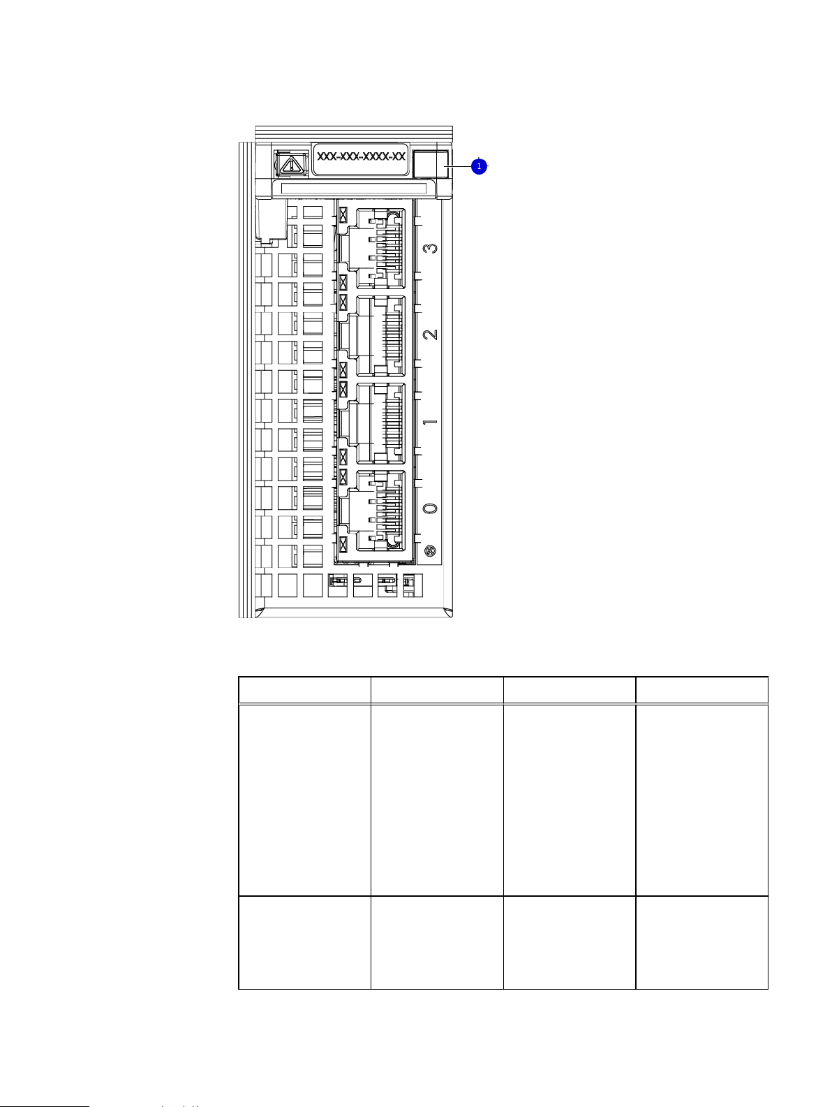
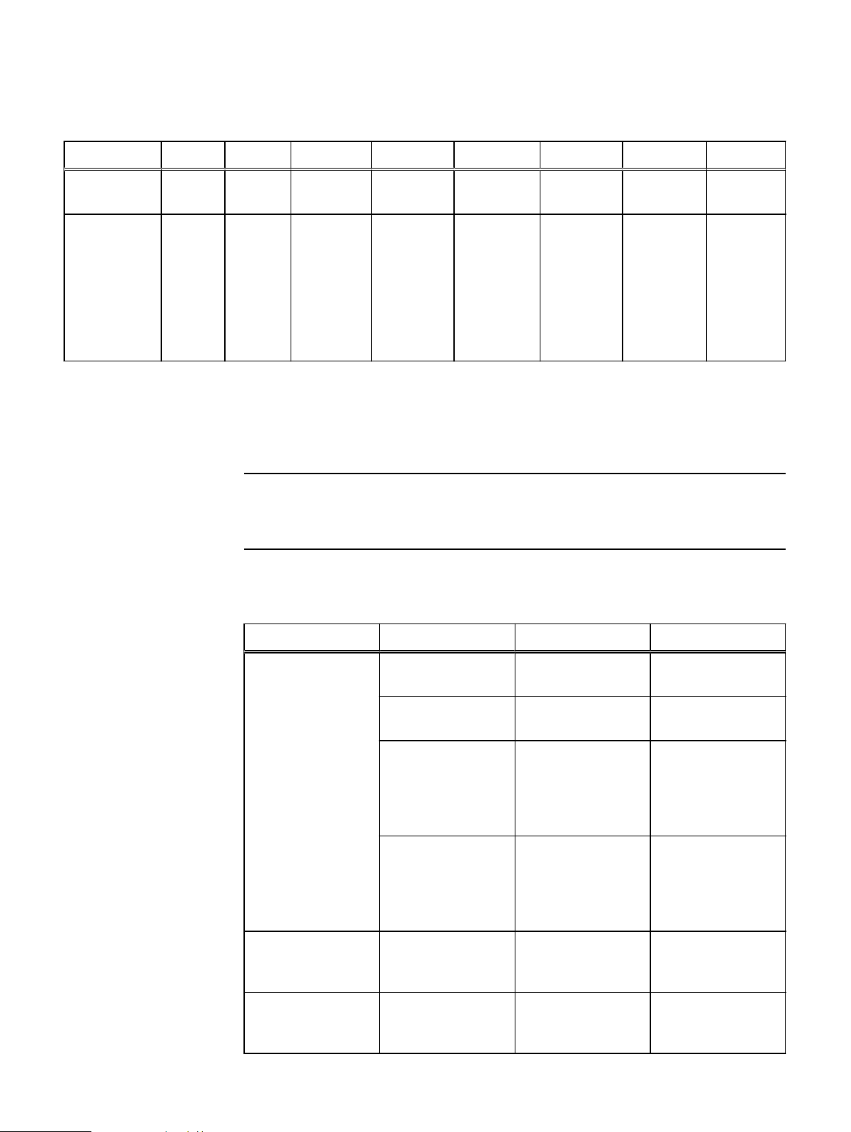
I/O module slot numbering
The eight I/O module slots are enumerated as Slot 0 (on the left when viewed from
the rear) through Slot 7. Ports on an I/O module are enumerated as 0 through 3, with
0 being on the bottom.
Figure 6
I/O module slot numbering
1. Slot 0
2. Slot 1
3. Slot 2
4. Slot 3
5. Slot 4
6. Slot 5
7. Slot 6
22 Data Domain DD6300, DD6800, and DD9300 Systems 6.1 Hardware Overview and Installation Guide

Data Domain DD6300, DD6800, and DD9300 Hardware Overview
8. Slot 7
Since DD6300, DD6800, and DD9300 is a data backup appliance, it is only supported
in fixed configurations. The fixed configurations define the exact slots into which the
I/O modules may be inserted. The processors directly drive the eight I/O module slots,
meaning all slots are full performance.
The non-optional SAS, NVRAM, and 10GBaseT I/O modules are allocated to fixed
slots. The optional Host Interface I/O modules are used for front end networking and
Fibre Channel connections. The quantity and type of these I/O modules is
customizable, and there are many valid configurations.
DD6300 slot map
Slot 0, Slot 1, Slot 2 (except when it is marked "Reserved") are populated with the
required I/O modules and are not optional. I/O module slots 3-7 contain optional Host
Interface I/O modules and can contain specific I/O modules or no I/O modules at all.
Table 12 DD6300 I/O slot module mapping
Tier Slot 0 Slot 1 Slot 2 Slot 3 Slot 4 Slot 5 Slot 6 Slot 7
AIO Expanded NVRAM
8g Model
3
AIO NVRAM
8g Model
3
a.
Optional in DD6300 configurations, but required with one or more external storage shelves.
Quad Port
10 GBaseT
Quad Port
10 GBaseT
Reserved (Optional)
Quad Port
10GbE SR,
Quad Port
10 GBaseT, or Dual
Port 16
Gbps Fibre
Channel
Reserved Quad Port
10GbE SR,
Quad Port
10 GBaseT, or Dual
Port 16
Gbps Fibre
Channel
(Optional)
Quad Port
10GbE SR,
Quad Port 10
GBase-T, or
Dual Port 16
Gbps Fibre
Channel
Quad Port
10GbE SR,
Quad Port 10
GBase-T, or
Dual Port 16
Gbps Fibre
Channel
(Optional)
Quad Port
10GbE SR,
Quad Port 10
GBase-T, or
Dual Port 16
Gbps Fibre
Channel
Quad Port
10GbE SR,
Quad Port 10
GBase-T, or
Dual Port 16
Gbps Fibre
Channel
(Optional)
Quad Port
10GbE SR,
Quad Port 10
GBase-T, or
Dual Port 16
Gbps Fibre
Channel
Quad Port
10GbE SR,
Quad Port 10
GBase-T, or
Dual Port 16
Gbps Fibre
Channel
(Optional)
Quad Port 6
Gbps SAS
Quad Port 6
Gbps SAS
DD6800 and DD9300 slot map
I/O module slots 3–6 contain optional Host Interface I/O modules and can contain
specific I/O modules or no I/O modules at all. Slot 0, Slot 1, Slot 2, and Slot 7 are
populated with the required I/O modules and are not optional.
a
a
Table 13
DD6800 and DD9300 I/O module slot mapping
Tier Slot 0 Slot 1 Slot 2 Slot 3 Slot 4 Slot 5 Slot 6 Slot 7
DLH NVRAM
DLH Extended
Retention/DD
Cloud Tier
8g Model
3
Quad
Port 10
GBase-T
Quad Port 6
Gbps SAS
Quad Port
10GbE SR,
Quad Port
10 GBase-T,
or Dual Port
16 Gbps
Quad Port
10GbE SR,
Quad Port 10
GBase-T, or
Dual Port 16
Gbps Fibre
Channel
Quad Port
10GbE SR,
Quad Port
10 GBase-T,
or Dual Port
16 Gbps
Quad Port
10GbE SR,
Quad Port 10
GBase-T, or
Dual Port 16
Gbps Fibre
Channel
I/O modules 23
Quad Port 6
Gbps SAS
Note
Data Domain DD6300, DD6800, and DD9300 Hardware Overview
Table 13 DD6800 and DD9300 I/O module slot mapping (continued)
Tier Slot 0 Slot 1 Slot 2 Slot 3 Slot 4 Slot 5 Slot 6 Slot 7
DLH High
Availability
NVRAM
8g Model
3
Quad
Port 10
GBase-T
for HA
interconn
ect
I/O module population rules
DD6300, DD6800, and DD9300 systems have eight slots for I/O modules. Slots 0, 1, 2,
and 7 are reserved. Slots 3, 4, 5, and 6 support host interface I/O modules. The
maximum supported number of any type of host interface I/O module is four.
A maximum of three Quad Port 10 GBase-T I/O modules are supported in slots 3-6
because of the mandatory Quad Port 10 GBase-T I/O module in slot 1.
The following table assigns rules for populating the I/O modules.
Quad Port 6
Gbps SAS
Fibre
Channel
Quad Port
10GbE SR,
Quad Port
10 GBase-T,
or Dual Port
16 Gbps
Fibre
Channel
Quad Port
10GbE SR,
Quad Port 10
GBase-T, or
Dual Port 16
Gbps Fibre
Channel
Fibre
Channel
Quad Port
10GbE SR,
Quad Port
10 GBase-T,
or Dual Port
16 Gbps
Fibre
Channel
Quad Port
10GbE SR,
Quad Port 10
GBase-T, or
Dual Port 16
Gbps Fibre
Channel
Quad Port 6
Gbps SAS
Table 14
I/O module slot population rules
Step I/O module name Slots Notes
Step 1: Populate
mandatory I/O
modules
Step 2: Populate all
Quad Port 10GbE SR
I/O modules
Step 3: Populate all
Quad Port 10 GBaseT I/O modules
NVRAM 8g Model 3 0 Mandatory for all
configurations
Quad Port 10 GBase-T1 Mandatory for all
configurations
Quad Port 6 Gbps
SAS
Quad Port 6 Gbps
SAS
Quad Port 10GbE SR 3, 4, 5, 6 Populate starting
Quad Port 10 GBase-T3, 4, 5, 6 Populate starting
2 Mandatory for
DD6800 and DD9300
DLH. This slot is
reserved for DD6300
configuration.
7 Mandatory for all
configurations except
DD6300. Reserved in
DD6300 for base
configuration.
from the lowest
available slot number.
from the lowest
available slot number.
24 Data Domain DD6300, DD6800, and DD9300 Systems 6.1 Hardware Overview and Installation Guide
 Loading...