

Page 1

Dell Latitude 7400
Setup and Specications
Regulatory Model: P100G
Regulatory Type: P100G001
Page 2

Notes, cautions, and warnings
NOTE: A NOTE indicates important information that helps you make better use of your product.
CAUTION: A CAUTION indicates either potential damage to hardware or loss of data and tells you how to avoid the problem.
WARNING: A WARNING indicates a potential for property damage, personal injury, or death.
© 2019 Dell Inc. or its subsidiaries. All rights reserved. Dell, EMC, and other trademarks are trademarks of Dell Inc. or its subsidiaries. Other trademarks
may be trademarks of their respective owners.
2019 - 04
Rev. A00
Page 3

Contents
1 Set up your computer.....................................................................................................................................5
2 Chassis.......................................................................................................................................................... 7
Front view........................................................................................................................................................................... 7
Left view..............................................................................................................................................................................8
Right view........................................................................................................................................................................... 8
Palmrest view..................................................................................................................................................................... 9
Bottom view......................................................................................................................................................................10
3 Keyboard shortcuts.......................................................................................................................................11
4 Technical specications................................................................................................................................12
System information...........................................................................................................................................................12
Processor...........................................................................................................................................................................12
Memory..............................................................................................................................................................................12
Storage...............................................................................................................................................................................13
Media card-reader............................................................................................................................................................ 13
Audio...................................................................................................................................................................................13
Video card..........................................................................................................................................................................14
Camera...............................................................................................................................................................................14
Ports and connectors.......................................................................................................................................................14
Wireless..............................................................................................................................................................................15
Wireless LAN card specications..............................................................................................................................15
WWAN card specications........................................................................................................................................15
Display................................................................................................................................................................................15
Keyboard............................................................................................................................................................................16
Touchpad........................................................................................................................................................................... 16
Touchpad gestures..................................................................................................................................................... 16
Operating system..............................................................................................................................................................16
Battery................................................................................................................................................................................17
Power adapter...................................................................................................................................................................18
Dimensions and weight.................................................................................................................................................... 18
Computer environment....................................................................................................................................................18
5 System setup...............................................................................................................................................20
Boot menu........................................................................................................................................................................ 20
Navigation keys................................................................................................................................................................20
Boot Sequence..................................................................................................................................................................21
System setup options.......................................................................................................................................................21
General options........................................................................................................................................................... 21
System conguration.................................................................................................................................................23
Video screen options................................................................................................................................................. 26
Security....................................................................................................................................................................... 26
Contents
3
Page 4

Secure boot................................................................................................................................................................ 28
Intel Software Guard Extensions options................................................................................................................29
Performance...............................................................................................................................................................29
Power management.................................................................................................................................................. 30
Post behavior.............................................................................................................................................................. 31
Manageability..............................................................................................................................................................32
Virtualization support.................................................................................................................................................33
Wireless options......................................................................................................................................................... 33
Maintenance...............................................................................................................................................................33
System logs.................................................................................................................................................................34
Updating the BIOS in Windows .....................................................................................................................................34
Updating BIOS on systems with BitLocker enabled..............................................................................................35
Updating your system BIOS using a USB ash drive............................................................................................35
System and setup password...........................................................................................................................................36
Assigning a system setup password........................................................................................................................ 36
Deleting or changing an existing system setup password.................................................................................... 36
6 Software......................................................................................................................................................38
Downloading drivers........................................................................................................................................................ 38
7 Getting help.................................................................................................................................................39
Contacting Dell.................................................................................................................................................................39
4
Contents
Page 5
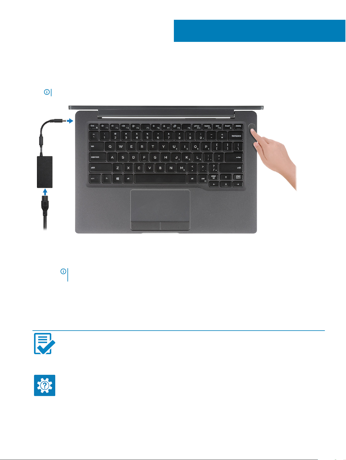
1 Connect the power adapter and press the power button.
NOTE: To conserve battery power, the battery might enter power saving mode.
1
Set up your computer
2 Finish the Windows system setup.
3 Follow the on-screen instructions to complete the setup. When setting up, Dell recommends that you:
• Connect to a network for Windows updates.
NOTE
: If connecting to a secured wireless network, enter the password for the wireless network access when
prompted.
• If connected to the internet, sign-in with or create a Microsoft account. If not connected to the internet, create an oine account.
• On the Support and Protection screen, enter your contact details.
4 Locate and use Dell apps from the Windows Start menu—Recommended
Table 1. Locate Dell apps
Dell apps Details
Dell Product Registration
Register your computer with Dell.
Dell Help & Support
Access help and support for your computer.
Set up your computer 5
Page 6
Dell apps Details
SupportAssist
Proactively checks the health of your computer’s hardware and
software.
Dell Update
Updates your computer with critical xes and important device
drivers as they become available.
Dell Digital Delivery
Download software applications including software that is
purchased but not pre-installed on your computer.
NOTE: Renew or upgrade your warranty by clicking the
warranty expiry date in SupportAssist.
5 Create recovery drive for Windows.
NOTE
: It is recommended to create a recovery drive to troubleshoot and x problems that may occur with Windows.
6 For more information, see Create a USB recovery drive for Windows.
6
Set up your computer
Page 7
Chassis
This chapter illustrates the multiple chassis views along with the ports and connectors and also explains the FN hot key combinations.
Topics:
• Front view
• Left view
• Right view
• Palmrest view
• Bottom view
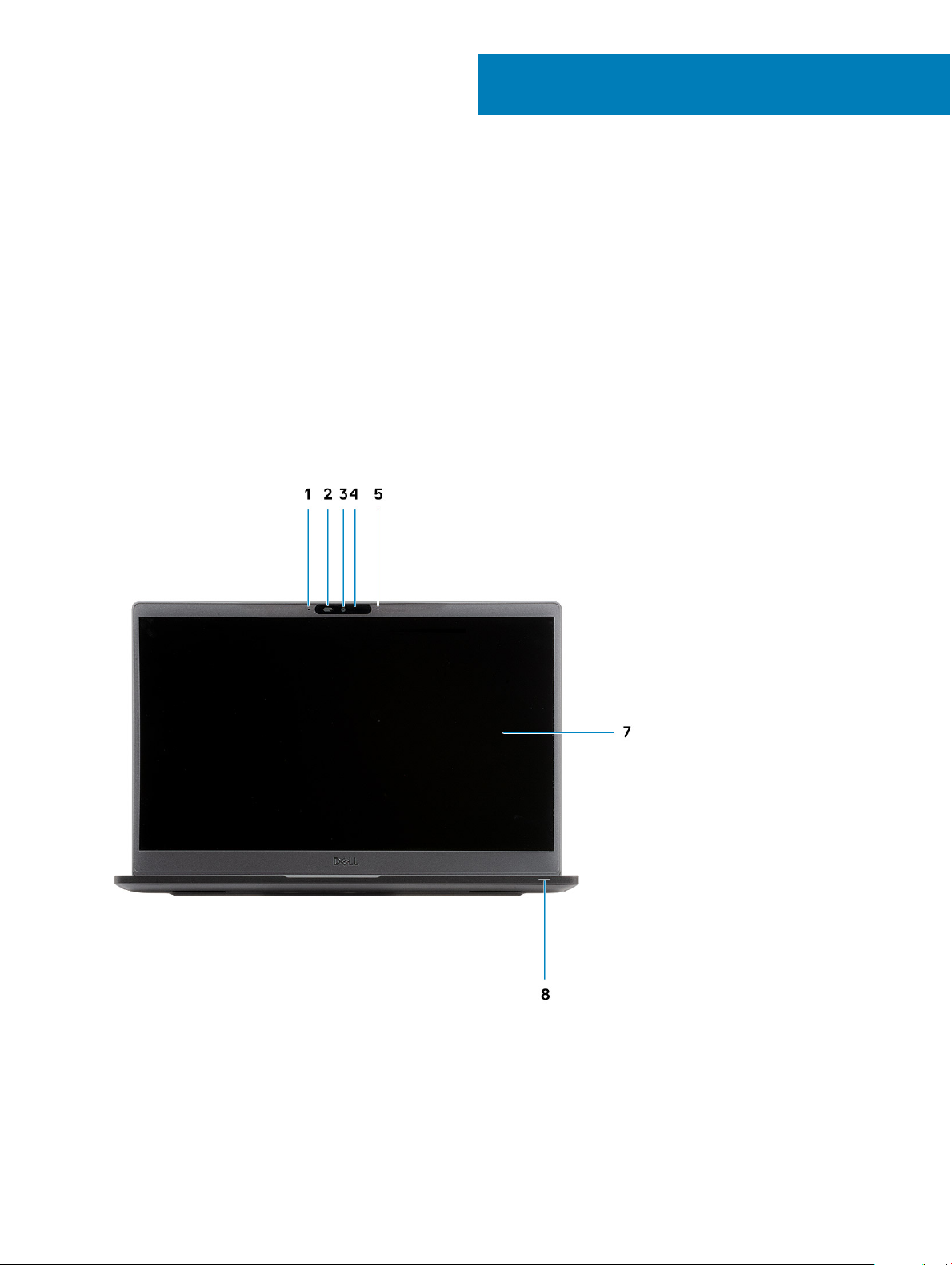
Front view
2
1 Microphone array
2 SafeView switch
3 Camera
4 Camera status LED
Chassis 7
Page 8
5 Microphone
6 Display panel
7 Battery status LED
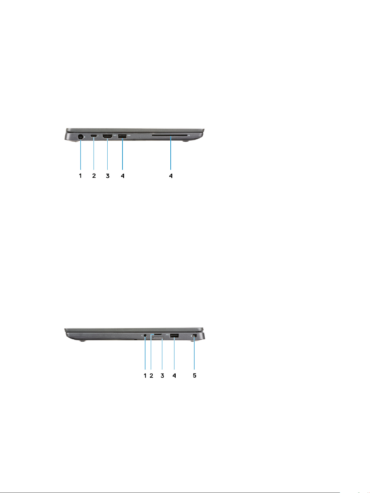
Left view
1 Power adapter port
2 USB Type-C 3.1 Gen 2 port (Thunderbolt)
3 HDMI 1.4a port
4 USB Type-A 3.1 Gen 1 port
5 Smart card slot
Right view
1 Universal audio port (Headset Jack + microphone-in + line-in support)
2 micro-SD 4.0 memory card reader
3 SIM card slot
4 USB Type-A 3.1 Gen 1 ports (PowerShare capable)
5 Noble wedge lock slot
Chassis
8
Page 9
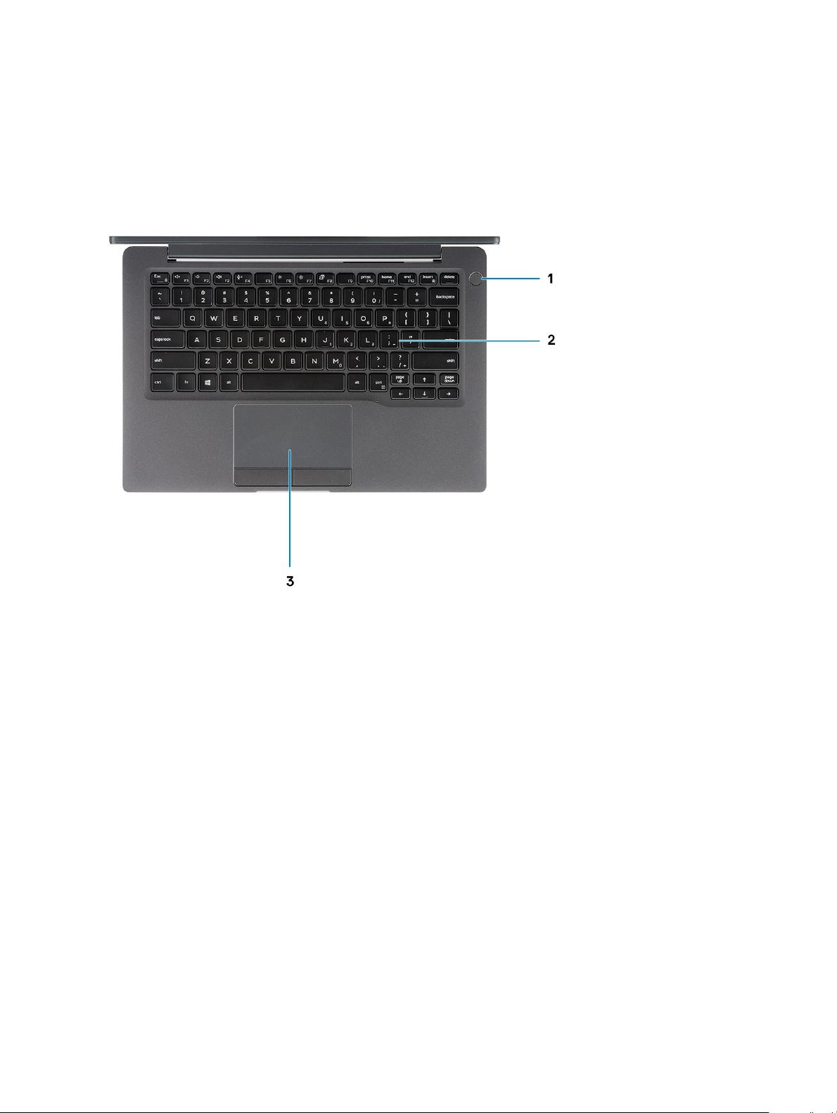
Palmrest view
1 Power button (with optional nger print reader - no LED)
2 Keyboard
3 Touchpad
Chassis
9
Page 10
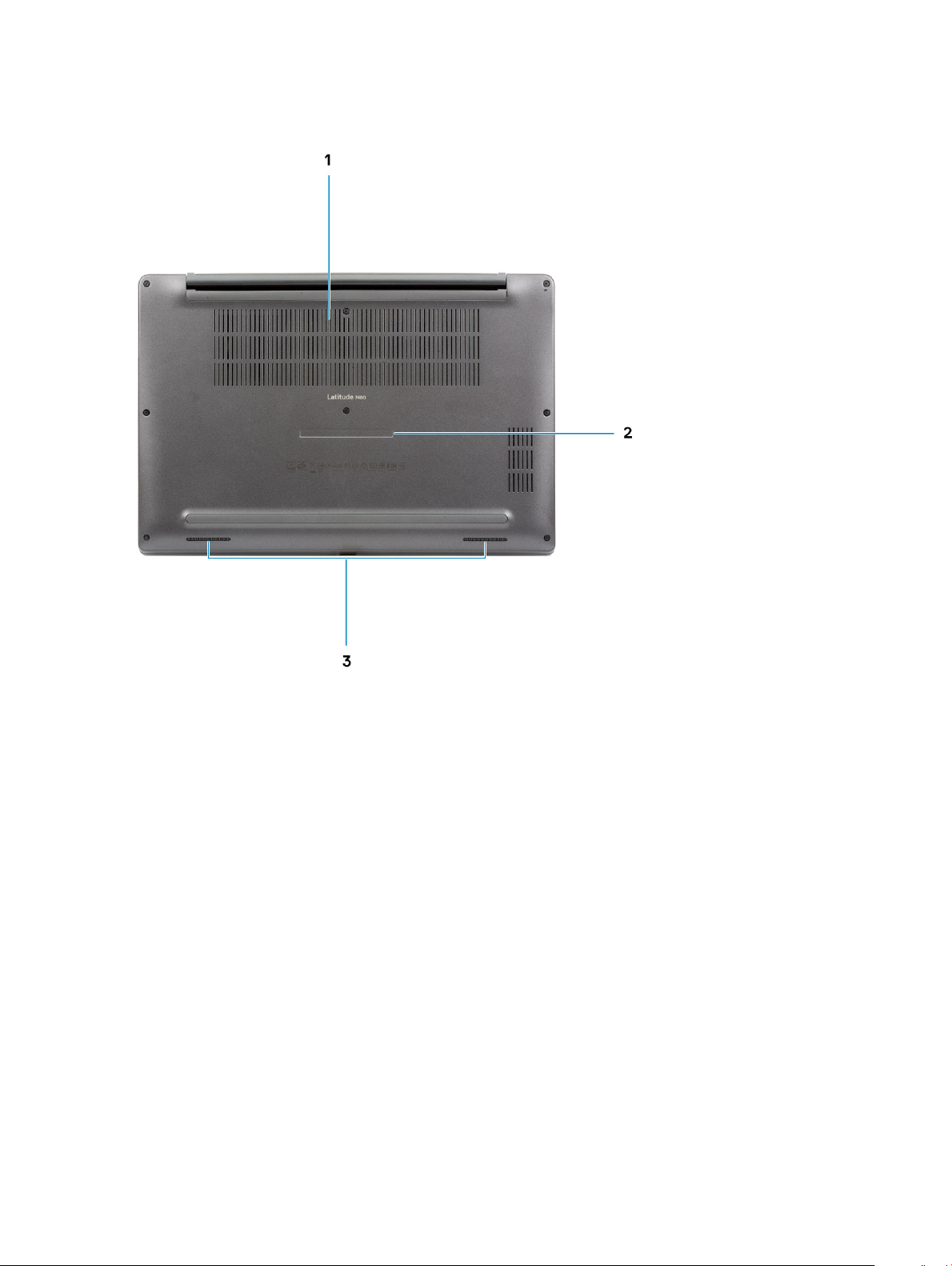
Bottom view
1 Thermal vent
2 Service tag label
3 Speakers
10
Chassis
Page 11

Keyboard shortcuts
NOTE: Keyboard characters may dier depending on the keyboard language conguration. Keys used for shortcuts remain the
same across all language congurations.
Table 2. List of keyboard shortcuts
Keys Description
Fn + Esc
Toggle Fn-key lock
3
Fn + F1
Fn + F2
Fn + F3
Fn + F4
Fn + F5
Fn + F6
Fn + F7
Fn + F8
Fn + F10
Fn + F11
Fn + F12
Fn + insert
Mute audio
Decrease volume
Increase volume
Mute microphone
Keyboard backlight
NOTE: Not applicable for non-
backlight keyboard.
Decrease brightness
Increase brightness
Switch to external display
Print Screen
Home
End
Num Lock
Keyboard shortcuts 11
Page 12

Technical specications
NOTE: Oerings may vary by region. The following specications are only those required by law to ship with your computer. For
more information about the conguration of your computer, go to Help and Support in your Windows operating system and
select the option to view information about your computer.
System information
Table 3. System information
Feature Specications
Chipset
Intel Chipset
4
DRAM bus width
FLASH EPROM
PCIe bus
64-bit
24 MB / 32 MB
100 Mhz
Processor
NOTE
: Processor numbers are not a measure of performance. Processor availability is subject to change and may vary by region/
country.
Table 4. Processor specications
Type UMA Graphics
8th Generation Intel core i5-8265U Processor (Quad Core (QC), 6M
SmartCache, base frequency 1.6 GHz, up to 3.9 GHz)
8th Generation Intel core i7-8565U Processor (QC, 8M SmartCache,
base frequency 1.8 GHz, up to 4.8 GHz)
8th Generation Intel core i5-8365U Processor (QC, 6M SmartCache,
base frequency 1.6 GHz, up to 4.1 GHz)
Intel UHD Graphics 620 (8th Generation Intel Core)
Intel UHD Graphics 620 (8th Generation Intel Core)
Intel UHD Graphics 620 (8th Generation Intel Core)
Memory
Table 5. Memory
Feature Specications
Minimum memory conguration
Maximum memory conguration
Number of slots
12 Technical specications
specications
4 GB
32 GB
Two SoDIMM
Page 13

Feature Specications
Memory options
• 4 GB - 1 x 4 GB
• 8 GB - 1 x 8 GB
• 8 GB - 2 x 4 GB
• 16 GB - 1 x16 GB
• 16 GB - 2 x 8 GB
• 32 GB - 2 x 16 GB
Type
Speed
DDR4
2400 MHz
Storage
Table 6. Storage specications
Type Form factor Interface Capacity
Solid-state drive M.2 2280 PCIe / SATA Up to 1 TB
Solid-state drive M.2 2230 (With
bracket)
Self Encrypting Drive (SED) / Opal SED M.2 2280 PCIe NVMe 256 GB
PCIe 128 GB
Media card-reader
Table 7. Media card-reader
Feature Specications
Type One micro-SD card slot
specications
Supported cards
• SD
• SDHC
• SDXC
Audio
Table 8. Audio
Feature Specications
Controller Realtek ALC3254 with Waves MaxxAudio Pro
Type Two-channel high-denition audio
Speakers Two (Directional speakers)
Interface
Internal speaker amplier 2 W (RMS) per channel
specications
Intel HDA bus
Technical specications 13
Page 14

Video card
Table 9. Video card specications
Controller Type CPU
Intel UHD
Graphics 620
UMA
Dependency
• 8th Gen Intel
• 8th Gen Intel
Core i5
processor
Core i7
processor
Graphics
memory type
Integrated Shared system
Capacity External display
memory
Camera
Table 10. Camera specications
Feature Specications
RGB camera: IR camera
Resolution
Diagonal viewing angle
Number of cameras 1 / 0
• Still image: 0.92 megapixels
• Video: 1280 x 720 at 30 fps
• Diagonal >/ 86.7° (tolerance +/- 3%)
• Vertical >/ 47°
• Still image: 0.92 megapixels
• Video: 1280 x 720 at 30 fps
support
HDMI 1.4b 4096 x 2304
Maximum
resolution
Video Max resolution 1280 x 720 (HD) at 30 FPS
Still image max resolution 0.92 megapixel (1280 x 720)
Ports and connectors
Table 11. Ports and connectors
Features Specications
Memory card reader micro-SD 4.0 memory card reader (optional)
USB
Security
Docking port Dell USB 3.0 Dock (UNO)
Audio
Video
• One USB Type-C 3.1 Gen 2 port (Thunderbolt)
• Two USB Type-A 3.1 Gen 1 ports (one PowerShare capable)
• Noble Wedge lock slot
• Smart card reader (optional)
Universal audio jack (Headset Jack + microphone-in + line-in
support)
HDMI 1.4a
14 Technical specications
Page 15

Wireless
Wireless LAN card specications
Table 12. Wireless LAN card specications
Wireless card options
Qualcomm QCA61x4A 802.11ac Dual Band (2x2) Wireless Adapter + Bluetooth 4.2 (non vPro)
Intel Dual-Band Wireless-AC 9560 Wi-Fi + Bluetooth 5.0 Wireless Card (2x2)(vPro)(Bluetooth Optional)
Intel Wi-Fi 6 AX200 2x2 .11ax 160MHz + Bluetooth 5.0
WWAN card specications
Table 13. Wireless WAN card specications
Wireless card option
Mobile Broadband Qualcomm Snapdragon X20 Global Gigabit LTE (Optional)
Display
Table 14. Display
Feature Specications
Type
Height (Active area) 173.95 mm (6.84 in)
Width (Active area) 309.4 mm (12.18 in)
Diagonal 355.6 mm (14.0 in)
Luminance/Brightness (typical)
Refresh rate
specications
• 14-inch HD AG (WXGA 1366x768), 220 nits, non-touch display
• 14-inch FHD AG (1920 x 1080), 300 nits, non-touch display
• 14-inch FHD AG (1920 x 1080), 300 nits, non-touch display with
Dynamic Privacy Dell SafeScreen
• 14-inch FHD AG (1920 x 1080), 300 nits, touch display
220 nits (Super Low Power) / 300 nits
60 Hz
Technical specications 15
Page 16

Keyboard
Table 15. Keyboard specications
Feature Specications
Number of keys
Size Full sized
Backlit keyboard Optional
Layout QWERTY / AZERTY / Kanji
• 81 (U.S)
• 82 (UK)
• 82 (Brazil)
• 85 (Japan)
• X= 19.05 mm key pitch
• Y= 19.05 mm key pitch
Touchpad
Table 16. Touchpad
Feature Specications
Resolution 1048 x 984
Dimensions
Multi-touch Congurable single nger and multi-nger gestures
specications
• Width: 3.91 inch (99.5 mm)
• Height: 2.08 inch (53 mm)
Touchpad gestures
For more information about touchpad gestures for Windows 10, see the Microsoft knowledge base article 4027871 at
support.microsoft.com.
Operating system
Table 17. Operating system
Feature Specications
Operating systems supported
• Windows 10 Home (64 bit)
• Windows 10 Pro (64 bit)
• Ubuntu
16 Technical specications
Page 17

Battery
Table 18. Battery specications
Type
Dimension Polymer 3-cell 42 WHr
Weight (maximum)
Voltage 11.4 VDC
Life span
• Polymer 3-cell 42 WHr
• Polymer 4-cell 60 WHr
• Polymer 4-cell 60 WHr (LCL)
• Width: 95.9 mm (3.78 in)
• Length: 200.5 mm (7.89 in)
• Height: 5.7 mm (0.22 in)
Polymer 4-cell 60 WHr and LCL
• Width: 95.9 mm (3.78 in)
• Length: 238 mm (9.37 in)
• Height: 5.7 mm (0.22 in)
• Polymer 3-cell 42 WHr: 192.5 g (0.42 lb)
• Polymer 4-cell and LCL: 270 g (0.60 lb)
• Polymer 3-cell 42 WHr and 4-cell 60 WHr (Standard Pack): 300
discharge / charge cycles
• Polymer 4-cell 60 WHr (LCL): 1000 discharge / charge cycles
Charging time when the computer is o (approximate)
Operating time Varies depending on operating conditions and can signicantly
Temperature range: Operating
Temperature range: Storage -20°C to 60°C (-4°F to 140°F)
Coin-cell battery CR 2032
NOTE: †For batteries with the ExpressCharge feature, the battery will typically have at least an 80% charge after about an hour
of charging with the system o, and fully charged in about 2 hours with the system o.
Enabling ExpressCharge requires that both the computer and the battery used be ExpressCharge capable. If these requirements are
not met, ExpressCharge will not be enabled.
• Standard Charge: 0°C to 50°C : 4 hours
• Express Charge†:
– 0°C to 15°C : 4 hours
– 16°C to 45°C : 2 hours
– 46°C to 50°C : 3 hours
reduce under certain power-intensive conditions
• Charging: 0°C to 50°C (32°F to 122°F)
• Discharging : 0°C to 70°C (32°F to 158°F)
Technical specications 17
Page 18

Power adapter
Table 19. Power adapter specications
Feature Specications
Type
• E5 65 W 7.4 mm Barrel Adapter
• E5 65 W BFR/PVC Halogen Free adapter, 7.4 mm barrel
• E5 65 W Rugged Adapter 7.4 mm barrel (India only)
• E5 90 W 7.4 mm Barrel Adapter
• 65 W adapter, Type-C
• 90 W adapter, Type-C
Input Voltage
Input current (maximum)
Input frequency
Output current
Rated output voltage
Temperature range (Operating)
Temperature range (Non-Operating)
Dimensions and weight
Table 20. Dimensions and weight
Feature Specications
Aluminum (Al) Carbon bre (CF)
Height Front - 16.75 mm(0.66 inch)
100 VAC - 240 VAC
• 1.7 A for 65 W
• 2.5 A for 90 W
50 Hz to 60 Hz
• 3.34 A for 65 W
• 4.62 A for 90 W
19.5 VDC
0°C to 40° C (32°F to 104°F)
40°C to 70°C (-40°F to 158°F)
Front - 17.82 mm(0.70 inch)
Rear - 18.20 mm(0.72 inch)
Width 321.35 mm(12.65 inch)
Depth 214.08 mm (8.42 inch)
Weight 1.4 kg(3.11 lb) 1.35 kg(2.99 lb)
Rear - 18.96 mm(0.75 inch)
Computer environment
Airborne contaminant level: G1 as dened by ISA-S71.04-1985
Technical specications
18
Page 19

Table 21. Computer environment
Temperature range
Operating Storage
0°C to 40°C (32°F to 104°F) -40°C to 65°C (-40°F to 149°F)
Relative humidity (maximum)
10% to 90% (non-condensing)
NOTE: Maximum dew point
temperature = 26°C
Vibration (maximum)
Shock (maximum)
Altitude (maximum)
0.66 GRMS 1.30 GRMS
†
140 G
0 m to 3048 m (0 ft to 10,000 ft) 0 m to 10,668 m (0 ft to 35,000 ft)
* Measured using a random vibration spectrum that simulates user environment.
† Measured using a 2 ms half-sine pulse when the hard drive is in use.
‡ Measured using a 2 ms half-sine pulse when the hard-drive head is in parked position.
0% to 95% (non-condensing)
NOTE: Maximum dew point
temperature = 33°C
‡
160 G
Technical specications 19
Page 20

5
System setup
CAUTION: Unless you are an expert computer user, do not change the settings in the BIOS Setup program. Certain changes can
make your computer work incorrectly.
NOTE: Before you change BIOS Setup program, it is recommended that you write down the BIOS Setup program screen
information for future reference.
Use the BIOS Setup program for the following purposes:
• Get information about the hardware installed in your computer, such as the amount of RAM and the size of the hard drive.
• Change the system conguration information.
• Set or change a user-selectable option, such as the user password, type of hard drive installed, and enabling or disabling base devices.
Topics:
• Boot menu
• Navigation keys
• Boot Sequence
• System setup options
• Updating the BIOS in Windows
• System and setup password
Boot menu
Press <F12> when the Dell logo appears to initiate a one-time boot menu with a list of the valid boot devices for the system. Diagnostics
and BIOS Setup options are also included in this menu. The devices listed on the boot menu depend on the bootable devices in the system.
This menu is useful when you are attempting to boot to a particular device or to bring up the diagnostics for the system. Using the boot
menu does not make any changes to the boot order stored in the BIOS.
The options are:
• UEFI Boot:
– Windows Boot Manager
•
• Other Options:
– BIOS Setup
– BIOS Flash Update
– Diagnostics
– Change Boot Mode Settings
Navigation keys
: For most of the System Setup options, changes that you make are recorded but do not take eect until you restart the
NOTE
system.
Keys Navigation
Up arrow Moves to the previous eld.
20 System setup
Page 21

Keys Navigation
Down arrow Moves to the next eld.
Enter Selects a value in the selected eld (if applicable) or follow the link in the eld.
Spacebar Expands or collapses a drop-down list, if applicable.
Tab Moves to the next focus area.
NOTE: For the standard graphics browser only.
Esc Moves to the previous page until you view the main screen. Pressing Esc in the main screen displays a message
that prompts you to save any unsaved changes and restarts the system.
Boot Sequence
Boot Sequence allows you to bypass the System Setup–dened boot device order and boot directly to a specic device (for example:
optical drive or hard drive). During the Power-on Self Test (POST), when the Dell logo appears, you can:
• Access System Setup by pressing F2 key
• Bring up the one-time boot menu by pressing F12 key
The one-time boot menu displays the devices that you can boot from including the diagnostic option. The boot menu options are:
• Removable Drive (if available)
• STXXXX Drive
NOTE
: XXX denotes the SATA drive number.
• Optical Drive (if available)
• SATA Hard Drive (if available)
• Diagnostics
NOTE
: Choosing Diagnostics, will display the ePSA diagnostics screen.
The boot sequence screen also displays the option to access the System Setup screen.
System setup options
: Depending on the laptop and its installed devices, the items listed in this section may or may not appear.
NOTE
General options
Table 22. General
Option Description
System Information
This section lists the primary hardware features of your computer.
The options are:
• System Information
– BIOS version
– Service Tag
– Asset Tag
– Ownership Tag
System setup 21
Page 22

Option Description
– Manufacture Date
– Express Service Code
• Memory Conguration
– Memory Installed
– Memory Available
– Memory Speed
– Memory Channel Mode
– Memory Technology
– DIMM A Size
– DIMM B Size
• Processor Information
– Processor Type
– Core Count
– Processor ID
– Current Clock Speed
– Minimum Clock Speed
– Maximum Clock Speed
– Processor L2 Cache
– Processor L3 Cache
– HT Capable
– 64-Bit Technology
• Device Information
– M.2 SATA
– M.2 SATA1
– M.2 PCIe SSD-0
– M.2 PCIe SSD-1
– Passthrough MAC Address
– Video Controller
– Video BIOS Version
– Video Memory
– Panel Type
– Native Resolution
– Privacy Screen
NOTE: Due to an amount of memory being
assigned for system use, "Memory Available" is less
than "Memory Installed". Note that certain
operating systems may not be able to use all the
available memory.
Battery Information
Boot Sequence
22 System setup
NOTE
: Applicable for e-Privacy version.
– Audio Controller
– Wi-Fi Device
– Bluetooth Device
Displays the battery status and the type of AC adapter connected
to the computer.
Allows you to change the order in which the computer attempts to
nd an operating system.
The options are:
• Windows Boot Manager—Default
• Boot List Option:
Page 23

Option Description
Allows you to add, delete and, view the boot list options.
Advanced Boot Options
UEFI Boot Path Security
Date/Time
Allows you to Enable Legacy Option ROMs.
• Enable UEFI Network Stack—Default
Allows you to control whether the system prompts the user to enter
the Admin password when booting to a UEFI boot path.
Click one of the following options:
• Always, Except Internal HDD—Default
• Always, Except Internal HDD & PXE
• Always
• Never
Allows you to set the date and time. The change to the system date
and time takes eect immediately.
System conguration
Table 23. System Conguration
Option Description
SATA Operation
Allows you to congure the operating mode of the integrated SATA
hard-drive controller.
Drives
SMART Reporting
USB Conguration
Click one of the following options:
• Disabled
• AHCI
• RAID On—Default
NOTE: SATA is congured to support RAID
mode.
These elds let you enable or disable various drives on board.
The options are:
• SATA-1
• SATA-2
• M.2 PCIe SSD-0
• M.2 PCIe SSD-1
This eld controls whether hard drive errors for integrated drives
are reported during startup.
The option is disabled by default.
Allows you to enable or disable the internal/integrated USB
conguration.
The options are:
• Enable USB Boot Support
• Enable External USB Ports
System setup 23
Page 24

Option Description
All the options are set by default.
NOTE: USB keyboard and mouse always work in the BIOS
setup irrespective of these settings.
Dell Type-C Dock Conguration
Thunderbolt™ Adapter Conguration
Thunderbolt™ Auto Switch
Allows you to connect to Dell WD and TB family of docks(Type-C
Docks) independent of USB and thunderbolt adapter conguration.
This option is enabled by default.
Allows you to enable or disable Thunderbolt options:
• Thunderbolt (Enabled by Defualt)
• Enable Thunderbolt Boot Support
• Enable Thunderbolt (and PCIe behind TBT) Pre-boot
With following security levels :
• No Security
• User Authentication (Enabled by Defualt)
• Secure Connect
• Display Port and USB Only
This option congures the method used by the Thunderbolt
controller to perform PCIe device enumeration.
• Auto Switch : The BIOS will automatically switch between BIOS
Assist and Native Thunderbolt PC device enumeration modes to
get all benets of the installed OS
• Native Enumeration: The BIOS will program the Thunderbolt
controller to Native mode ( Auto Switching is disabled)
• BIOS Assist Enumeration: The BIOS will program the
Thunderbolt controller to BIOS Assist mode ( Auto Switching is
disabled)
USB PowerShare
Audio
Keyboard Illumination
NOTE: A reboot is required for these changes to take
eect.
This option enable/disable the USB PowerShare feature behavior.
This option is disabled by default.
Allows you to enable or disable the integrated audio controller. By
default, the Enable Audio option is selected.
The options are:
• Enable Microphone
• Enable Internal Speaker
This option is set by default.
This eld lets you choose the operating mode of the keyboard
illumination feature.
• Disabled: The Keyboard illumination will always be o or 0%.
• Dim: Enable the keyboard illumination feature at 50%
brightness.
• Bright (Enabled by Defualt): Enable the keyboard illumination
feature at 100% brightness level.
24 System setup
Page 25

Option Description
NOTE: Option present on system opted with backlit
keyboard.
Keyboard Backlight Timeout on AC
Keyboard Backlight Timeout on Battery
This feature denes the timeout value for the keyboard backlight
when an AC adapter is plugged into the system.
Options are:
• 5 seconds
• 10 seconds(Default)
• 15 seconds
• 30 seconds
• 1 minute
• 5 minute
• 15 minute
• Never
NOTE: Option present on system opted with backlit
keyboard.
This feature denes the timeout value for the keyboard backlight
when the system is running only on battery power.
Options are:
• 5 seconds
• 10 seconds(Default)
• 15 seconds
• 30 seconds
• 1 minute
• 5 minute
• 15 minute
• Never
Unobtrusive Mode
Fingerprint Reader
Miscellaneous devices
NOTE: Option present on system opted with backlit
keyboard.
When enabled, pressing Fn+F7 will turn o all light and sound
emission in the system. Press Fn+F7 to resume normal operation.
Default is Disabled.
Enable or disable the Fingerprint Reader or the Fingerprint Reader
Device's Single Sign On capability.
• Enable Fingerprint Reader Device: Enabled by Default
NOTE: Option present on system opted with nger print
reader on the power button.
Allows you to enable or disable various on board devices.
• Enable Camera—Default
• Enable Secure Digital (SD) Card
• Secure Digital (SD) Card Boot - Disabled
• Secure Digital Card (SD) Read-Only Mode - Disabled
System setup 25
Page 26

Video screen options
Table 24. Video
Option Description
LCD Brightness
Allows you to set the display brightness depending upon the power
source. On Battery(100% is default) and On AC (100 % is default).
Privacy Screen
Security
Table 25. Security
Option Description
Admin Password
Allows you to set, change, or delete the administrator(admin) password.
The entries to set password are:
• Enter the old password:
• Enter the new password:
• Conrm new password:
This option Enables or Disables the Privacy Screen if the Panel
supports this feature. The options are:
• Disabled: When Disabled the privacy screen is not applied to
the embedded display panel.
• Enabled — Default: When enabled, the privacy screen is
applied to the embedded display panel and can be toggled
between public mode and privacy mode using the Fn+F9 key
combination on the embedded keyboard.
• Always On: When always on the privacy screen is always on
and cannot be turned o by the user.
NOTE: This option is present if the display supports e-
Privacy panel.
System Password
26 System setup
Click OK once you set the password.
NOTE: For the rst time login, "Enter the old password:" eld is marked to "Not set". Hence,
password has to be set for the rst time you login and then you can change or delete the
password.
Allows you to set, change, or delete the System password.
The entries to set password are:
• Enter the old password:
• Enter the new password:
• Conrm new password:
Click OK once you set the password.
NOTE: For the rst time login, "Enter the old password:" eld is marked to "Not set". Hence,
password has to be set for the rst time you login and then you can change or delete the
password.
Page 27

Option Description
Strong Password
Allows you to enforce the option to always set strong password.
• Enable Strong Password
This option is not set by default.
Password Conguration
Password Bypass
Password Change
Non-Admin Setup Changes
UEFI Capsule Firmware
Updates
You can dene the length of your password. Min = 4, Max = 32
Allows you to bypass the System password and the Internal HDD password, when it is set, during a system
restart.
Click one of the options:
• Disabled—Default
• Reboot bypass
Allows you to change the System password when the administrator password is set.
• Allow Non-Admin Password Changes
This option is set by default.
Allows you to determine whether changes to the setup options are allowed when an Administrator
Password is set. If disabled the setup options are locked by the admin password.
• Allow Wireless Switch Changes
This option is not set by default.
Allows you to update the system BIOS via UEFI capsule update packages.
• Enable UEFI Capsule Firmware Updates
This option is set by default.
HDD Security
TPM 2.0 Security
Absolute® This eld lets you Enable, Disable, or Permanently Disable the BIOS module interface of the optional
This options controls the mechanism used by BIOS to block external Self Encrypting Drives (SED)
management software to take ownership of the SED. The options are:
• SED Block SID Authentication
• PPI Bypass for SED Block SID Command
Both the options are disabled by default.
NOTE: This option is applicable with laptops shipped with SED
Allows you to enable or disable the Trusted Platform Module (TPM) during POST.
The options are:
• TPM On—Default
• Clear
• PPI Bypass for Enable Command—Default
• PPI Bypass for Disbale Command
• PPI Bypass for Clear Command
• Attestation Enable—Default
• Key Storage Enable—Default
• SHA-256—Default
Absolute Persistence Module service from Absolute® Software. This option is enabled by default.
System setup 27
Page 28

Option Description
OROM Keyboard Access
This option determines whether users are able to enter Option ROM Conguration screens via hotkey
during boot. Specically this settings is capable of preventing access to Intel® RAID(Ctrl+I) or Intel®
Management Engine BIOS Extension (Ctrl+P/F12).
Options are:
• Enable— Default
• One Time Enable
• Disable
Admin Setup Lockout
Master Password Lockout
SMM Security Mitigation
Allows you to prevent users from entering Setup when an administrator password is set.
• Enable Admin Setup Lockout
This option is not set by default.
Allows you to disable master password support.
• Enable Master Password Lockout
This option is not set by default.
NOTE: Hard Disk password should be cleared before the settings can be changed.
Allows you to enable or disable additional UEFI SMM Security Mitigation protection.
• SMM Security Mitigation
This option is not set by default.
Secure boot
Table 26. Secure Boot
Option Description
Secure Boot Enable
Allows you to enable or disable the Secure Boot Feature.
Secure Boot Mode
Expert Key Management
28 System setup
• Secure Boot Enable—Default
Changes to the Secure Boot operation mode modies the
behaviour of Secure Boot to allow evaluation of UEFI driver
signatures.
Choose one of the option:
• Deployed Mode—Default
• Audit Mode
Allows you to enable or disable Expert Key Management.
• Enable Custom Mode
This option is not set by default.
The Custom Mode Key Management options are:
• PK—Default
• KEK
• db
Page 29

Option Description
• dbx
Intel Software Guard Extensions options
Table 27. Intel Software Guard Extensions
Option Description
Intel SGX Enable
This eld species you to provide a secured environment for
running code/storing sensitive information in the context of the
main OS.
Click one of the following options:
• Disabled
• Enabled
• Software controlled—Default
Enclave Memory Size
This option sets SGX Enclave Reserve Memory Size
Click one of the following options:
• 32 MB
• 64 MB
• 128 MB—Default
Performance
Table 28. Performance
Option Description
Multi Core Support
Intel SpeedStep
This eld species whether the process has one or all cores
enabled. The performance of some applications improves with the
additional cores.
• All—Default
• 1
• 2
• 3
Allows you to enable or disable the Intel SpeedStep mode of
processor.
C-States Control
• Enable Intel SpeedStep
This option is set by default.
Allows you to enable or disable the additional processor sleep
states.
• C states
This option is set by default.
System setup 29
Page 30

Option Description
Intel® TurboBoost™
This option enables or disables the Intel® TurboBoost™ mode of
the processor
Hyper-Thread Control
Power management
Table 29. Power Management
Option Description
AC Behavior
Enable Intel Speed Shift
technology
Auto On Time
Allows you to enable or disable the computer from turning on automatically when an AC adapter is
connected.
• Wake on AC
This option is not set by default.
This option is used to enable/disable Intel Speed Shift Technology.
This option is not set by default.
Allows you to set the time at which the computer must turn on automatically.
Allows you to enable or disable the HyperThreading in the
processor.
• Disabled
• Enabled—Default
USB Wake Support
Wireless Radio Control
Block Sleep
The options are:
• Disabled—Default
• Every Day
• Weekdays
• Select Days
This option is not set by default.
Allows you to enable USB devices to wake the system from standby.
• Wake on Dell USB-C Dock
This option is set by default.
This option if enabled, will sense the connection of the system to a wired network and subsequently
disable the selected wireless radios (WLAN and/or WWAN). Upon disconnection from the wired network
the selected wireless radio will ne enabled.
• Control WLAN radio
• Control WWAN radio
Both the options are not set by default.
This option lets you to block entering to sleep in OS environment.
This option is not set by default.
Peak Shift
30 System setup
Allows you enable of disable the Peak shift feature. This feature when enabled minimizes the AC power
usage at times of peak demand. Battery doesnot charge between the Peak Shift start and end time
Page 31

Option Description
Peak Shift Start and End Time can be congured for all weekdays
This option set the battery threshold value (15 % to 100 %)
Advanced Battery Charge
Conguration
Primary Battery Charge
Conguration
Post behavior
Table 30. POST Behavior
This option enables you to maximize the battery health. By enabling this option, your system uses the
standard charging algorithm and other techniques, during the non-work hours to improve the battery
health.
Advanced Battery Charge Mode can be congured for all weekdays
Allows you to select the charging mode for the battery.
The options are:
• Adaptive—Default
• Standard - Fully charges your battery at a standard rate.
• ExpressCharge™- The battery charges over a shorter period of time using Dell’s fast charging
technology.
• Primarily AC use
• Custom
If Custom Charge is selected, you can also congure Custom Charge Start and Custom Charge Stop.
NOTE: All charging mode may not be available for all the batteries.
Option Description
Adapter Warnings
Keyboard Embeded
Numlock Enable
Fn Lock Options
Fastboot
Allows you to enable or disable the system setup (BIOS) warning messages when you use certain power
adapters.
• Enable Adapter Warnings—Default
This option lets you choose one of two methods to enable the keypad that is embedded in the internal
keyboard. The options are:
• Fn Key Only
• By Numlock
Allows you to enable or disable the Numlock function when the system boots.
• Enable Numlock—Default
Allows you to let hot key combinations Fn + Esc toggle the primary behavior of F1–F12, between their
standard and secondary functions. If you disable this option, you cannot toggle dynamically the primary
behavior of these keys.
• Fn Lock—Default
Click one of the following options:
• Lock Mode Disable/Standard
• Lock Mode Enable/Secondary—Default
Allows you to speed up the boot process by bypassing some of the compatibility steps.
System setup 31
Page 32

Option Description
Click one of the following options:
• Minimal—Default
• Thorough
• Auto
Extended BIOS POST Time
Full Screen Logo
Warnings and Errors
MAC Address Pass-Through
Allows you to create an additional preboot delay.
Click one of the following options:
• 0 seconds—Default
• 5 seconds
• 10 seconds
Allows you to display full screen logo, if your image matches screen resolution.
• Enable Full Screen Logo
This option is not set by default.
Allows you to select dierent options to either stop, prompt and wait for user input, continue when
warnings are detected but pause on errors, or continue when either warnings or errors are detected during
the POST process.
Click one of the following options:
• Prompt on Warnings and Errors—Default
• Continue on Warnings
• Continue on Warnings and Errors
This feature replaces the external NIC MAC address (in a supported dock or dongle) with the selected
MAC address from the system. The default option is to use the Passthrough MAC address.
Manageability
NOTE
: This option is present if the system has Intel V-Pro enabled.
Table 31. Manageability
Option Description
Intel AMT Capability
USB Provision
MEBx Hotkey
This option allows to enable and disable the Intel AMT Capabilities
of the system. The options are:
• Disabled
• Enabled
• Restrict MEBx Access
When enabled Intel AMT can be provisioned using the local
provisioning le via a USB storage device. This option is disabled by
default.
This option species whether the MEBx Hotkey function should be
enabled when the system boots.
32 System setup
Page 33

Virtualization support
Table 32. Virtualization Support
Option Description
Virtualization
This option species whether a Virtual Machine Monitor (VMM) can utilize the additional hardware
capabilities provided by the Intel Virtualization technology.
• Enable Intel Virtualization Technology
This option is set by default.
VT for Direct I/O
Trusted Execution
Enables or disables the Virtual Machine Monitor (VMM) from utilizing the additional hardware
capabilities provided by the Intel Virtualization technology for direct I/O.
• Enable VT for Direct I/O
This option is set by default.
This option species whether a Measured Virtual Machine Monitor (MVMM) can utilize the additional
hardware capabilities provided by Intel® Trusted Execution Technology.
NOTE: The TPM has to be enabled and activated and Virtualization Technology and VT for
Direct I/O must be enabled to use this feature.
Wireless options
Table 33. Wireless
Option Description
Wireless Switch
Allows to set the wireless devices that can be controlled by the
wireless switch.
The options are:
• WWAN / GPS
• WLAN
• Bluetooth®
Maintenance
Table 34. Maintenance
Option Description
Service Tag
Asset Tag
Displays the service tag of your computer.
Allows you to create a system asset tag if an asset tag is not already set.
This option is not set by default.
All the options are enabled by default.
System setup 33
Page 34

Option Description
BIOS Downgrade
Allows you to ash previous revisions of the system rmware.
• Allow BIOS Downgrade
This option is set by default.
Data Wipe
Bios Recovery
Allows you to securely erase data from all internal storage devices.
• Wipe on Next Boot
This option is not set by default.
BIOS Recovery from Hard Drive—This option is set by default. Allows you to recover the corrupted BIOS
from a recovery le on the HDD or an external USB key.
BIOS Auto-Recovery— Allows you to recover the BIOS automatically.
NOTE: BIOS Recovery from Hard Drive eld should be enabled.
Always Perform Integrity Check—Performs integrity check on every boot.
System logs
Table 35. System Logs
Option Description
BIOS events
Thermal Events
Allows you to view and clear the System Setup (BIOS) POST events.
Allows you to view and clear the System Setup (Thermal) events.
Power Events
Allows you to view and clear the System Setup (Power) events.
Updating the BIOS in Windows
It is recommended to update your BIOS (System Setup), when you replace the system board or if an update is available. For laptops, ensure
that your computer battery is fully charged and connected to a power outlet.
: If BitLocker is enabled, it must be suspended prior to updating the system BIOS, and then re-enabled after the BIOS
NOTE
update is completed.
1 Restart the computer.
2 Go to Dell.com/support.
• Enter the Service Tag or Express Service Code and click Submit.
• Click Detect Product and follow the instructions on screen.
3 If you are unable to detect or nd the Service Tag, click Choose from all products.
4 Choose the Products category from the list.
: Choose the appropriate category to reach the product page
NOTE
5 Select your computer model and the Product Support page of your computer appears.
6 Click Get drivers and click Drivers and Downloads.
The Drivers and Downloads section opens.
7 Click Find it myself.
8 Click BIOS to view the BIOS versions.
9 Identify the latest BIOS le and click Download.
34
System setup
Page 35
10 Select your preferred download method in the Please select your download method below window, click Download File.
The File Download window appears.
11 Click Save to save the le on your computer.
12 Click Run to install the updated BIOS settings on your computer.
Follow the instructions on the screen.
Updating BIOS on systems with BitLocker enabled
CAUTION: If BitLocker is not suspended before updating the BIOS, the next time you reboot the system it will not recognize the
BitLocker key. You will then be prompted to enter the recovery key to progress and the system will ask for this on each reboot. If
the recovery key is not known this can result in data loss or an unnecessary operating system re-install. For more information on
this subject, see Knowledge Article: https://www.dell.com/support/article/sln153694
Updating your system BIOS using a USB ash drive
If the system cannot load into Windows but there is still a need to update the BIOS, download the BIOS le using another system and save
it to a bootable USB Flash Drive.
NOTE: You will need to use a bootable USB Flash drive. Please refer to the following article for further details: https://
www.dell.com/support/article/us/en/19/sln143196/
1 Download the BIOS update .EXE le to another system.
2 Copy the le e.g. O9010A12.EXE onto the bootable USB Flash drive.
3 Insert the USB Flash drive into the system that requires the BIOS update.
4 Restart the system and press F12 when the Dell Splash logo appears to display the One Time Boot Menu.
5 Using arrow keys, select USB Storage Device and click Return.
6 The system will boot to a Diag C:\> prompt.
7 Run the le by typing the full lename e.g. O9010A12.exe and press Return.
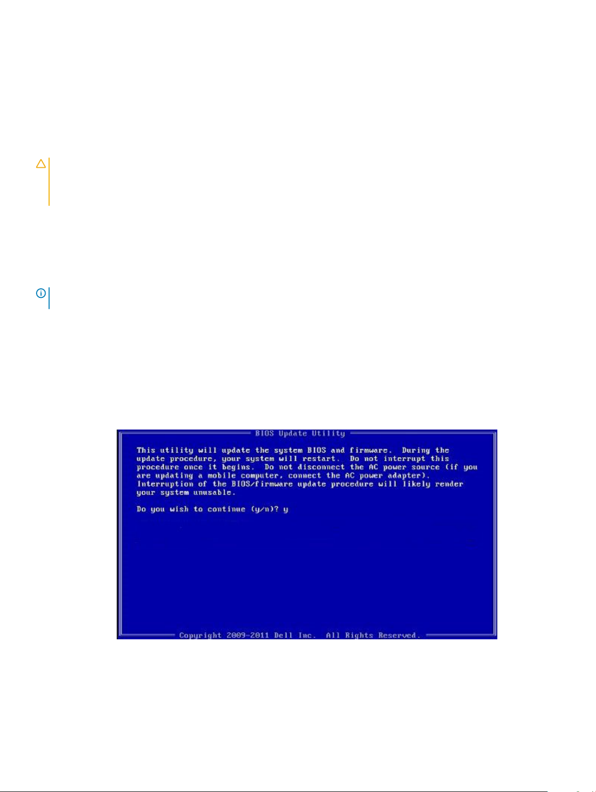
8 The BIOS Update Utility will load, follow the instructions on screen.
Figure 1. DOS BIOS Update Screen
System setup
35
Page 36

System and setup password
Table 36. System and setup password
Password type Description
System password Password that you must enter to log on to your system.
Setup password Password that you must enter to access and make changes to the
BIOS settings of your computer.
You can create a system password and a setup password to secure your computer.
CAUTION: The password features provide a basic level of security for the data on your computer.
CAUTION: Anyone can access the data stored on your computer if it is not locked and left unattended.
NOTE: System and setup password feature is disabled.
Assigning a system setup password
You can assign a new System or Admin Password only when the status is in Not Set.
To enter the system setup, press F2 immediately after a power-on or re-boot.
1 In the System BIOS or System Setup screen, select Security and press Enter.
The Security screen is displayed.
2 Select System/Admin Password and create a password in the Enter the new password eld.
Use the following guidelines to assign the system password:
• A password can have up to 32 characters.
• The password can contain the numbers 0 through 9.
• Only lower case letters are valid, upper case letters are not allowed.
• Only the following special characters are allowed: space, (”), (+), (,), (-), (.), (/), (;), ([), (\), (]), (`).
3 Type the system password that you entered earlier in the Conrm new password eld and click OK.
4 Press Esc and a message prompts you to save the changes.
5 Press Y to save the changes.
The computer reboots.
Deleting or changing an existing system setup password
Ensure that the Password Status is Unlocked (in the System Setup) before attempting to delete or change the existing System and/or
Setup password. You cannot delete or change an existing System or Setup password, if the Password Status is Locked.
To enter the System Setup, press F2 immediately after a power-on or reboot.
1 In the System BIOS or System Setup screen, select System Security and press Enter.
The System Security screen is displayed.
2 In the System Security screen, verify that Password Status is Unlocked.
3 Select System Password, alter or delete the existing system password and press Enter or Tab.
4 Select Setup Password, alter or delete the existing setup password and press Enter or Tab.
: If you change the System and/or Setup password, re-enter the new password when prompted. If you delete the
NOTE
System and/or Setup password, conrm the deletion when prompted.
36 System setup
Page 37

5 Press Esc and a message prompts you to save the changes.
6 Press Y to save the changes and exit from System Setup.
The computer reboot.
System setup 37
Page 38

This chapter details the supported operating systems along with instructions on how to install the drivers.
Downloading drivers
1 Turn on the notebook.
2 Go to Dell.com/support.
3 Click Product Support, enter the Service Tag of your notebook, and then click Submit.
NOTE: If you do not have the Service Tag, use the auto detect feature or manually browse for your notebook model.
4 Click Drivers and Downloads.
5 Select the operating system installed on your notebook.
6 Scroll down the page and select the driver to install.
7 Click Download File to download the driver for your notebook.
8 After the download is complete, navigate to the folder where you saved the driver le.
9 Double-click the driver le icon and follow the instructions on the screen.
6
Software
38 Software
Page 39

7
Getting help
Contacting Dell
NOTE: If you do not have an active Internet connection, you can nd contact information on your purchase invoice, packing slip,
bill, or Dell product catalog.
Dell provides several online and telephone-based support and service options. Availability varies by country and product, and some services
may not be available in your area. To contact Dell for sales, technical support, or customer service issues:
1 Go to Dell.com/support.
2 Select your support category.
3 Verify your country or region in the Choose a Country/Region drop-down list at the bottom of the page.
4 Select the appropriate service or support link based on your need.
Getting help 39
 Loading...