

Page 1

Dell™ OptiPlex™ 755
User’s Guide
Models: DCTR, DCNE, DCSM, and DCCY
www.dell.com | support.dell.com
Page 2

Notes, Notices, and Cautions
NOTE: A NOTE indicates important information that helps you make better use of your computer.
NOTICE: A NOTICE indicates either potential damage to hardware or loss of data and tells you how to avoid the
problem.
CAUTION: A CAUTION indicates a potential for property damage, personal injury, or death.
If you purchased a Dell™ n Series computer, any references in this document to Microsoft® Windows®
operating systems are not applicable.
____________________
Information in this document is subject to change without notice.
© 2007–2008 Dell Inc. All rights reserved.
Reproduction in any manner whatsoever without the written permission of Dell Inc. is strictly forbidden.
Trademarks used in this text: Dell, the DELL logo, OptiPlex, Trave lLite, OpenManage, and StrikeZone are trademarks of Dell Inc.; Intel,
SpeedStep, and Celeron are registered trademarks and Core and vPro are trademarks of Intel Corporation in the U.S and other countries;
Microsoft, MS-DOS, Windows, Windows Vista, and the Windows Start button are either registered trademarks or trademarks of Microsoft
Corporation in the United States and/or other countries; Bluetooth is a trademark owned by Bluetooth SIG, Inc. and is used by Dell Inc. under
license. ENERGY STAR is a registered trademark of the U.S. Environmental Protection Agency. As an ENERGY STAR partner, Dell Inc. has
determined that this product meets the ENERGY STAR guidelines for energy efficiency.
Other trademarks and trade names may be used in this document to refer to either the entities claiming the marks and names or their products.
Dell Inc. disclaims any proprietary interest in trademarks and trade names other than its own.
Models: DCTR, DCNE, DCSM, and DCC
September 2009 P/N JN460 Rev. A03
Page 3

Contents
1 Finding Information
2 Before You Begin
Recommended Tools . . . . . . . . . . . . . . . . . . . . . . . . . . . . 21
Turning Off Your Computer
. . . . . . . . . . . . . . . . . . . . . . . 21
Before Working Inside Your Computer
. . . . . . . . . . . . . . . . . . . 21
3 Mini Tower Computer
About Your Mini Tower Computer. . . . . . . . . . . . . . . . . . . . . . 23
Front View
Back View
Back Panel Connectors
Removing the Computer Cover
Inside Your Computer
Chassis Intrusion Switch
Removing the Chassis Intrusion Switch
Replacing the Chassis Intrusion Switch
Resetting the Chassis Intrusion Detector
System Board Components
. . . . . . . . . . . . . . . . . . . . . . . . . . . . . . 23
. . . . . . . . . . . . . . . . . . . . . . . . . . . . . . 25
. . . . . . . . . . . . . . . . . . . . . . . . 26
. . . . . . . . . . . . . . . . . . . . . . . 27
. . . . . . . . . . . . . . . . . . . . . . . . . . . 29
. . . . . . . . . . . . . . . . . . . . . . . . . . 29
. . . . . . . . . . . . . . . . . 30
. . . . . . . . . . . . . . . . 30
. . . . . . . . . . . . . . . . 31
. . . . . . . . . . . . . . . . . . . . . . . . . 32
4 Mini Tower Computer Specifications
Cards . . . . . . . . . . . . . . . . . . . . . . . . . . . . . . . . . . . 41
Installing a PCI or PCI Express Card
Removing a PCI or PCI Express Card
PS/2 Serial Port Adapter
. . . . . . . . . . . . . . . . . . . . . . . . 47
Installing a PS/2 Serial Port Adapter
Removing a PS/2 Serial Port Adapter
Installing eSATA
. . . . . . . . . . . . . . . . . . . . . . . . . . . . 51
. . . . . . . . . . . . . . . . . . 41
. . . . . . . . . . . . . . . . . . 45
. . . . . . . . . . . . . 47
. . . . . . . . . . . . . 49
Contents 3
Page 4

Drives . . . . . . . . . . . . . . . . . . . . . . . . . . . . . . . . . . . 53
General Drive Installation Guidelines
Connecting Drive Cables
Data Interface Connectors
Power Cable Connectors
Connecting and Disconnecting Drive Cables
Hard Drive
. . . . . . . . . . . . . . . . . . . . . . . . . . . . . . 55
Removing a Hard Drive
Installing a Hard Drive
Adding a Second Hard Drive
Floppy Drive
. . . . . . . . . . . . . . . . . . . . . . . . . . . . . 63
Removing the Floppy Drive
Installing the Floppy Drive
Media Card Reader
. . . . . . . . . . . . . . . . . . . . . . . . . . 66
Removing the Media Card Reader
Installing the Media Card Reader
Optical Drive
. . . . . . . . . . . . . . . . . . . . . . . . . . . . . 69
Removing an Optical Drive
Installing an Optical Drive
. . . . . . . . . . . . . . . . . . 53
. . . . . . . . . . . . . . . . . . . 54
. . . . . . . . . . . . . . . . . . 54
. . . . . . . . . . . . . . . . . . 54
. . . . . . . . . 55
. . . . . . . . . . . . . . . . . . . 55
. . . . . . . . . . . . . . . . . . . . 57
. . . . . . . . . . . . . . . . . 60
. . . . . . . . . . . . . . . . . . 64
. . . . . . . . . . . . . . . . . . 64
. . . . . . . . . . . . . . 66
. . . . . . . . . . . . . . . 67
. . . . . . . . . . . . . . . . . . 69
. . . . . . . . . . . . . . . . . . 70
4 Contents
Processor
. . . . . . . . . . . . . . . . . . . . . . . . . . . . . . . . . 73
Removing the Processor
Installing the Processor
I/O Panel
. . . . . . . . . . . . . . . . . . . . . . . . . . . . . . . . . 77
Removing the I/O Panel
Replacing the I/O Panel
Power Supply
. . . . . . . . . . . . . . . . . . . . . . . . . . . . . . . 79
Replacing the Power Supply
DC Power Connectors
DC Power Connector P1
DC Power Connector P2
DC Power Connectors P3, P5, P8, and P9
DC Power Connector P7
DC Power Connector P10
Speakers
. . . . . . . . . . . . . . . . . . . . . . . . . . . . . . . . . 85
Installing a Speaker
Removing a Speaker
. . . . . . . . . . . . . . . . . . . . . . . . 73
. . . . . . . . . . . . . . . . . . . . . . . . 74
. . . . . . . . . . . . . . . . . . . . . . . . 77
. . . . . . . . . . . . . . . . . . . . . . . . 78
. . . . . . . . . . . . . . . . . . . . . . 79
. . . . . . . . . . . . . . . . . . . . . . . . . 81
. . . . . . . . . . . . . . . . . . . 81
. . . . . . . . . . . . . . . . . . . 83
. . . . . . . . . . . 83
. . . . . . . . . . . . . . . . . . . 84
. . . . . . . . . . . . . . . . . . 84
. . . . . . . . . . . . . . . . . . . . . . . . . . 85
. . . . . . . . . . . . . . . . . . . . . . . . . 86
Page 5

5 Desktop Computer
About Your Desktop Computer . . . . . . . . . . . . . . . . . . . . . . . 87
Front View
Back View
Back Panel Connectors
. . . . . . . . . . . . . . . . . . . . . . . . . . . . . . 87
. . . . . . . . . . . . . . . . . . . . . . . . . . . . . . 88
. . . . . . . . . . . . . . . . . . . . . . . . 89
Removing the Computer Cover
Inside Your Computer
Chassis Intrusion Switch
Removing the Chassis Intrusion Switch
Replacing the Chassis Intrusion Switch
Resetting the Chassis Intrusion Detector
Removing the Heat Sink Assembly
System Board Components
. . . . . . . . . . . . . . . . . . . . . . . 90
. . . . . . . . . . . . . . . . . . . . . . . . . . . 91
. . . . . . . . . . . . . . . . . . . . . . . . . . 92
. . . . . . . . . . . . . . . . . 92
. . . . . . . . . . . . . . . . 93
. . . . . . . . . . . . . . . . 93
. . . . . . . . . . . . . . . . . . . . . 94
. . . . . . . . . . . . . . . . . . . . . . . . . 95
6 Desktop Computer Specifications
Cards . . . . . . . . . . . . . . . . . . . . . . . . . . . . . . . . . . 103
PCI Cards
PS/2 Serial Port Adapter
eSATA
. . . . . . . . . . . . . . . . . . . . . . . . . . . . . . 103
Installing a PCI Card
Removing a PCI Card
Installing a PCI Card in the Riser-Card Cage
Removing a PCI Card From the Riser-Card Cage
Installing a PS/2 Serial Port Adapter
Removing a PS/2 Serial Port Adapter
. . . . . . . . . . . . . . . . . . . . 103
. . . . . . . . . . . . . . . . . . . 109
. . . . . . . . 111
. . . . . . . 114
. . . . . . . . . . . . . . . . . . . . . . . 116
. . . . . . . . . . . . 116
. . . . . . . . . . . . 118
Installing a PS/2 Serial Port Adapter in the
Riser-Card Cage
. . . . . . . . . . . . . . . . . . . . . . 119
Removing a PS/2 Serial Port Adapter From the
Riser-Card Cage
. . . . . . . . . . . . . . . . . . . . . . . . . . . . . . . 123
Installing eSATA Without a Riser
Installing eSATA With a Riser
. . . . . . . . . . . . . . . . . . . . . . 121
. . . . . . . . . . . . . . 123
. . . . . . . . . . . . . . . 124
Contents 5
Page 6

Drives . . . . . . . . . . . . . . . . . . . . . . . . . . . . . . . . . . 127
General Drive Installation Guidelines
Connecting Drive Cables
Data Interface Connectors
Power Cable Connectors
Connecting and Disconnecting Drive Cables
Drive Inserts
. . . . . . . . . . . . . . . . . . . . . . . . . . . . 129
Removing Drive Inserts
Replacing Drive Inserts
Optical Drive
. . . . . . . . . . . . . . . . . . . . . . . . . . . . 131
Removing an Optical Drive
Installing an Optical Drive
Floppy Drive
. . . . . . . . . . . . . . . . . . . . . . . . . . . . 134
Removing a Floppy Drive
Installing a Floppy Drive
Media Card Reader
. . . . . . . . . . . . . . . . . . . . . . . . . 137
Removing a Media Card Reader
Installing a Media Card Reader
Hard Drive
. . . . . . . . . . . . . . . . . . . . . . . . . . . . . 142
Removing a Hard Drive
Installing a Hard Drive
Replacing a Second Hard Drive
. . . . . . . . . . . . . . . . . 127
. . . . . . . . . . . . . . . . . . 128
. . . . . . . . . . . . . . . . . 128
. . . . . . . . . . . . . . . . . 128
. . . . . . . . 129
. . . . . . . . . . . . . . . . . . 129
. . . . . . . . . . . . . . . . . . 131
. . . . . . . . . . . . . . . . . 131
. . . . . . . . . . . . . . . . . 132
. . . . . . . . . . . . . . . . . . 135
. . . . . . . . . . . . . . . . . . 136
. . . . . . . . . . . . . . 138
. . . . . . . . . . . . . . 139
. . . . . . . . . . . . . . . . . . 142
. . . . . . . . . . . . . . . . . . . 143
. . . . . . . . . . . . . . 146
6 Contents
Processor
. . . . . . . . . . . . . . . . . . . . . . . . . . . . . . . . 149
Removing the Processor
Installing the Processor
I/O Panel
. . . . . . . . . . . . . . . . . . . . . . . . . . . . . . . . 153
Removing the I/O Panel
Replacing the I/O Panel
Power Supply
. . . . . . . . . . . . . . . . . . . . . . . . . . . . . . 155
Replacing the Power Supply
DC Power Connectors
DC Power Connector P1
DC Power Connector P2
DC Power Connector P3
DC Power Connector P4
DC Power Connector P5 and P6
. . . . . . . . . . . . . . . . . . . . . . . 149
. . . . . . . . . . . . . . . . . . . . . . . 150
. . . . . . . . . . . . . . . . . . . . . . . 153
. . . . . . . . . . . . . . . . . . . . . . . 154
. . . . . . . . . . . . . . . . . . . . . 155
. . . . . . . . . . . . . . . . . . . . . . . . 157
. . . . . . . . . . . . . . . . . . 157
. . . . . . . . . . . . . . . . . . 159
. . . . . . . . . . . . . . . . . . 160
. . . . . . . . . . . . . . . . . . 160
. . . . . . . . . . . . . . 160
Page 7

Speakers . . . . . . . . . . . . . . . . . . . . . . . . . . . . . . . . 163
Installing a Speaker
Removing a Speaker
. . . . . . . . . . . . . . . . . . . . . . . . . 163
. . . . . . . . . . . . . . . . . . . . . . . . 163
7 Small Form Factor Computer
About Your Small Form Factor Computer . . . . . . . . . . . . . . . . . 165
Front View
Back View
Back Panel Connectors
. . . . . . . . . . . . . . . . . . . . . . . . . . . . . 165
. . . . . . . . . . . . . . . . . . . . . . . . . . . . . 166
. . . . . . . . . . . . . . . . . . . . . . . 167
Removing the Computer Cover
Inside Your Computer
Chassis Intrusion Switch
Removing the Chassis Intrusion Switch
Replacing the Chassis Intrusion Switch
Resetting the Chassis Intrusion Detector
System Board Components
Small Form Factor Computer Specifications
Cards
. . . . . . . . . . . . . . . . . . . . . . . . . . . . . . . . . . 181
PCI Cards
. . . . . . . . . . . . . . . . . . . . . . . . . . . . . . 181
Installing a PCI Card
Removing a PCI Card
PCI Express and DVI Cards
Installing a PCI Express x16 Card or DVI Card
Removing a PCI Express x16 Card or DVI Card
PS/2 Serial Port Adapter
Installing a PS/2 Serial Port Adapter
Removing a PS/2 Serial Port Adapter
eSATA
. . . . . . . . . . . . . . . . . . . . . . . . . . . . . . . 193
Installing eSATA
. . . . . . . . . . . . . . . . . . . . . . 168
. . . . . . . . . . . . . . . . . . . . . . . . . . 169
. . . . . . . . . . . . . . . . . . . . . . . . . 170
. . . . . . . . . . . . . . . . 170
. . . . . . . . . . . . . . . 171
. . . . . . . . . . . . . . . 171
. . . . . . . . . . . . . . . . . . . . . . . . 172
. . . . . . . . . . . . . . . . 175
. . . . . . . . . . . . . . . . . . . . 181
. . . . . . . . . . . . . . . . . . . 184
. . . . . . . . . . . . . . . . . . . . . 185
. . . . . . . . 186
. . . . . . . 189
. . . . . . . . . . . . . . . . . . . . . . . 191
. . . . . . . . . . . . 191
. . . . . . . . . . . . 192
. . . . . . . . . . . . . . . . . . . . . 193
Drives
. . . . . . . . . . . . . . . . . . . . . . . . . . . . . . . . . . 195
General Installation Guidelines
Connecting Drive Cables
Data Interface Connectors
. . . . . . . . . . . . . . . . . . . . 195
. . . . . . . . . . . . . . . . . . 196
. . . . . . . . . . . . . . . . . 196
Contents 7
Page 8

Power Cable Connectors . . . . . . . . . . . . . . . . . 196
Connecting and Disconnecting Drive Cables
Hard Drive
. . . . . . . . . . . . . . . . . . . . . . . . . . . . . 197
Removing a Hard Drive
Installing a Hard Drive
Replacing a Hard Drive Fan
Optical Drive
. . . . . . . . . . . . . . . . . . . . . . . . . . . . 204
Removing an Optical Drive
Installing an Optical Drive
Floppy Drive
. . . . . . . . . . . . . . . . . . . . . . . . . . . . 206
Removing a Floppy Drive
Installing a Floppy Drive
Media Card Reader
. . . . . . . . . . . . . . . . . . . . . . . . . 209
Removing a Media Card Reader
Replacing a Media Card Reader
. . . . . . . . 196
. . . . . . . . . . . . . . . . . . 197
. . . . . . . . . . . . . . . . . . . 199
. . . . . . . . . . . . . . . . . . . . . 202
. . . . . . . . . . . . . . . . . 204
. . . . . . . . . . . . . . . . . 205
. . . . . . . . . . . . . . . . . . 206
. . . . . . . . . . . . . . . . . . 208
. . . . . . . . . . . . . . 210
. . . . . . . . . . . . . . 211
Processor
. . . . . . . . . . . . . . . . . . . . . . . . . . . . . . . . 213
Removing the Processor
Installing the Processor
I/O Panel
. . . . . . . . . . . . . . . . . . . . . . . . . . . . . . . . 217
Removing the I/O Panel
Replacing the I/O Panel
Power Supply
. . . . . . . . . . . . . . . . . . . . . . . . . . . . . . 219
Replacing the Power Supply
DC Power Connectors
DC Power Connector P1
DC Power Connector P2
DC Power Connectors P3
DC Power Connector P5
DC Power Connector P6
Speakers
. . . . . . . . . . . . . . . . . . . . . . . . . . . . . . . . 225
Installing a Speaker
Removing a Speaker
. . . . . . . . . . . . . . . . . . . . . . . 213
. . . . . . . . . . . . . . . . . . . . . . . 214
. . . . . . . . . . . . . . . . . . . . . . . 217
. . . . . . . . . . . . . . . . . . . . . . . 218
. . . . . . . . . . . . . . . . . . . . . 219
. . . . . . . . . . . . . . . . . . . . . . . . 221
. . . . . . . . . . . . . . . . . . 221
. . . . . . . . . . . . . . . . . . 223
. . . . . . . . . . . . . . . . . 223
. . . . . . . . . . . . . . . . . . 224
. . . . . . . . . . . . . . . . . . 224
. . . . . . . . . . . . . . . . . . . . . . . . . 225
. . . . . . . . . . . . . . . . . . . . . . . . 225
8 Contents
Page 9

8 Ultra Small Form Factor Computer
About Your Ultra Small Form Factor Computer. . . . . . . . . . . . . . . 227
Front View
Side View
Back View
Back Panel Connectors
. . . . . . . . . . . . . . . . . . . . . . . . . . . . . 227
. . . . . . . . . . . . . . . . . . . . . . . . . . . . . . 228
. . . . . . . . . . . . . . . . . . . . . . . . . . . . . 229
. . . . . . . . . . . . . . . . . . . . . . . 229
Connecting a VGA Monitor
Connecting Two Monitors
. . . . . . . . . . . . . . . . . 230
. . . . . . . . . . . . . . . . . 231
Removing the Computer Cover
Inside Your Computer
Chassis Intrusion Switch
Removing the Chassis Intrusion Switch
Replacing the Chassis Intrusion Switch
Resetting the Chassis Intrusion Detector
System Board Components
Cable Cover (Optional)
Attaching the Cable Cover
Removing the Cable Cover
Connecting the AC Power Adapter
Dell Badge
. . . . . . . . . . . . . . . . . . . . . . . . . . . . . . . 239
Ultra Small Form Factor Computer Specifications
Drives
. . . . . . . . . . . . . . . . . . . . . . . . . . . . . . . . . . 247
General Installation Guidelines
Connecting Drive Cables
Data Interface Connectors
Power Cable Connectors
Connecting and Disconnecting Drive Cables
Hard Drive
. . . . . . . . . . . . . . . . . . . . . . . . . . . . . 248
Installing a Hard Drive
Replacing a Hard Drive Fan
. . . . . . . . . . . . . . . . . . . . . . 232
. . . . . . . . . . . . . . . . . . . . . . . . . . 233
. . . . . . . . . . . . . . . . . . . . . . . . . 233
. . . . . . . . . . . . . . . . 234
. . . . . . . . . . . . . . . 234
. . . . . . . . . . . . . . . 235
. . . . . . . . . . . . . . . . . . . . . . . . 236
. . . . . . . . . . . . . . . . . . . . . . . . 237
. . . . . . . . . . . . . . . . . 237
. . . . . . . . . . . . . . . . . 237
. . . . . . . . . . . . . . . . . . . . 238
. . . . . . . . . . . . . 241
. . . . . . . . . . . . . . . . . . . . 247
. . . . . . . . . . . . . . . . . . 247
. . . . . . . . . . . . . . . . . 247
. . . . . . . . . . . . . . . . . 248
. . . . . . . . 248
. . . . . . . . . . . . . . . . . . . 249
. . . . . . . . . . . . . . . . 252
Contents 9
Page 10

Module Bay . . . . . . . . . . . . . . . . . . . . . . . . . . . . . . . 255
Installing a Device When Your Computer Is Turned Off
Removing and Installing a Device When Your Computer Is Running
Microsoft
Securing a Device in the Module Bay
®
Windows
®
. . . . . . . . . . . . . . . . . . . . . . . 258
. . . . . . . . . . . . . . . . 259
. . . . . . . . 255
Processor
Speakers
. . . . . . . . . . . . . . . . . . . . . . . . . . . . . . . . 261
. . . . . . . . . . . . . . . . . . . . . . . . . . . . . . . . 267
Installing a Speaker
Removing a Speaker
. . . . . . . . . . . . . . . . . . . . . . . . . 267
. . . . . . . . . . . . . . . . . . . . . . . . 268
9 Advanced Features
LegacySelect Technology Control . . . . . . . . . . . . . . . . . . . . 269
Manageability
DASH
Active Management Technology
Alert Standard Format
Dell OpenManage™ Applications
Dell Client Manager (DCM)
. . . . . . . . . . . . . . . . . . . . . . . . . . . . . . 269
. . . . . . . . . . . . . . . . . . . . . . . . . . . . . . . . 269
. . . . . . . . . . . . . . . . . . . 270
iAMT Features
Out of Band Management
Accessing iAMT setup
Turning Off iAMT
USB Provisioning
Dell Client Manager (DCM) Console
. . . . . . . . . . . . . . . . . . . . . . 270
. . . . . . . . . . . . . . . . . 271
. . . . . . . . . . . . . . . . . . . 271
. . . . . . . . . . . . . . . . . . . . . 271
. . . . . . . . . . . . . . . . . . . . . 271
. . . . . . . . . . . . . . . . . . . . . . . . 272
. . . . . . . . . . . . . . . . . . 272
. . . . . . . . . . . . . . . . . . . . . 273
. . . . . . . . . . . . 273
10 Contents
Physical Security
Chassis Intrusion Detection
Option Settings
. . . . . . . . . . . . . . . . . . . . . . . . . . . . 274
. . . . . . . . . . . . . . . . . . . . . 274
. . . . . . . . . . . . . . . . . . . . . . . . . . . 274
Padlock Ring and Security Cable Slot
Trusted Platform Module (TPM)
Enabling the TPM Feature
Security Management Software
Computer Tracking Software
. . . . . . . . . . . . . . . . . . . . . 275
. . . . . . . . . . . . . . . . . . . . . . 275
. . . . . . . . . . . . . . . . . . . . . 276
. . . . . . . . . . . . . . . . . . . . . . . 276
About Smart Cards and Fingerprint Readers
. . . . . . . . . . . . . . . . 274
. . . . . . . . . . . . . . . . 276
Page 11

Password Protection. . . . . . . . . . . . . . . . . . . . . . . . . . . 277
System Password
Option Settings
Assigning a System Password
Typing Your System Password
Deleting or Changing an Existing System Password
Administrator Password
Option Settings
Assigning an Administrator Password
. . . . . . . . . . . . . . . . . . . . . . . . . . 277
. . . . . . . . . . . . . . . . . . . . . . 277
. . . . . . . . . . . . . . . 277
. . . . . . . . . . . . . . . 278
. . . . . 278
. . . . . . . . . . . . . . . . . . . . . . . 279
. . . . . . . . . . . . . . . . . . . . . . 279
. . . . . . . . . . . 279
Operating Your Computer With an Administrator
Password Enabled
Deleting or Changing an Existing Administrator Password
Disabling a Forgotten Password and Setting a New Password
. . . . . . . . . . . . . . . . . . . . . 279
. . 280
. . . . . 280
System Setup
Overview
Entering System Setup
System Setup Screens
System Setup Options
Boot Sequence
. . . . . . . . . . . . . . . . . . . . . . . . . . . . . . 280
. . . . . . . . . . . . . . . . . . . . . . . . . . . . . . 280
. . . . . . . . . . . . . . . . . . . . . . . . 280
. . . . . . . . . . . . . . . . . . . . . . . . 281
. . . . . . . . . . . . . . . . . . . . . . . . 281
. . . . . . . . . . . . . . . . . . . . . . . . . . . 287
Option Settings
. . . . . . . . . . . . . . . . . . . . . . 287
Changing Boot Sequence for the Current Boot
Changing Boot Sequence for Future Boots
Booting to a USB Device
Memory Key
Floppy Drive
Jumper Settings
Clearing Forgotten Passwords
Clearing CMOS Settings
Hyperthreading and Multi-Core Technology
. . . . . . . . . . . . . . . . . . . . . . . . . 288
. . . . . . . . . . . . . . . . . . . . . . . . . . . . 288
. . . . . . . . . . . . . . . . . . . . . . . . . . . . 289
. . . . . . . . . . . . . . . . . . . . . . . . . . . . . 289
. . . . . . . . . . . . . . . . . . . . . . 290
. . . . . . . . . . . . . . . . . . . . . . . . . 291
. . . . . . . . . . . . . . . . 292
Power Management for Windows XP and Windows Vista
Options in Windows XP
Standby Mode
Hibernate Mode
Power Options Properties
Power Schemes Tab
. . . . . . . . . . . . . . . . . . . . . . . 292
. . . . . . . . . . . . . . . . . . . . . . 292
. . . . . . . . . . . . . . . . . . . . . . 293
. . . . . . . . . . . . . . . . . 293
. . . . . . . . . . . . . . . . . . . 293
. . . . . . . 287
. . . . . . . . . 288
. . . . . . . . . 292
Contents 11
Page 12

Advanced Tab. . . . . . . . . . . . . . . . . . . . . . . 294
Hibernate Tab
Options in Windows Vista
Sleep Mode
. . . . . . . . . . . . . . . . . . . . . . . . 295
Hibernate Mode
Configuring Power Management Settings
. . . . . . . . . . . . . . . . . . . . . . . 294
. . . . . . . . . . . . . . . . . . . . . . 294
. . . . . . . . . . . . . . . . . . . . . . 295
. . . . . . . . . 295
About RAID Configurations
Verifying That RAID Is Working
RAID Level 0
. . . . . . . . . . . . . . . . . . . . . . . . . . . . 296
RAID Level 1 Configuration
Configuring Your Computer for RAID
Setting Your Computer to RAID-Enabled Mode
. . . . . . . . . . . . . . . . . . . . . . . . 295
. . . . . . . . . . . . . . . . . . . 296
. . . . . . . . . . . . . . . . . . . . . 297
. . . . . . . . . . . . . . . . . 297
. . . . . . . 297
Configuring Your Computer for RAID Using the Intel RAID
Option ROM Utility
. . . . . . . . . . . . . . . . . . . . . 298
Configuring Your Computer for RAID Using the Intel Matrix
Storage Manager
. . . . . . . . . . . . . . . . . . . . . 299
Recovering From a Single Hard Drive Failure (RAID 1) Using the Intel
Matrix Storage Manager
Migrating to a RAID Level 0 Configuration
Migrating to a RAID Level 1 Configuration
. . . . . . . . . . . . . . . . . . . . . . 300
. . . . . . . . . . . . . . 301
. . . . . . . . . . . . . . 301
10 Battery
Replacing the Battery . . . . . . . . . . . . . . . . . . . . . . . . . . 303
11 Replacing the System Board
Removing the System Board: Mini Tower, Desktop, Small Form Factor, and
Ultra Small Form Factor Computers
Mini Tower System Board Screws
Desktop System Board Screws
Small Form Factor System Board Screws
Ultra Small Form Factor System Board Screws
. . . . . . . . . . . . . . . . . . . . 307
. . . . . . . . . . . . . . . . . . 308
. . . . . . . . . . . . . . . . . . . 309
. . . . . . . . . . . . . . . 310
. . . . . . . . . . . . 311
12 Contents
Replacing the System Board: Mini Tower, Desktop, Small Form Factor, and
Ultra Small Form Factor Computers
. . . . . . . . . . . . . . . . . . . . 311
Page 13

12 Memory
DDR2 Memory Overview. . . . . . . . . . . . . . . . . . . . . . . 313
Addressing Memory Configurations
Installing Memory
Removing Memory
. . . . . . . . . . . . . . . . . . . . . . . . . . 314
. . . . . . . . . . . . . . . . . . . . . . . . . 316
. . . . . . . . . . . . . . . . . 314
13 Replacing the Computer Cover
Mini-Tower, Desktop, and Small Form Factor Computers . . . . . . . . . 317
Ultra Small Form Factor Computers
. . . . . . . . . . . . . . . . . . . . 317
14 Installing Your Computer in an Enclosure
15 Cleaning Your Computer
Computer, Keyboard, and Monitor . . . . . . . . . . . . . . . . . . . . 323
Mouse
. . . . . . . . . . . . . . . . . . . . . . . . . . . . . . . . . 323
Cleaning a Non-Optical Mouse
Cleaning an Optical Mouse
Floppy Drive
CDs and DVDs
. . . . . . . . . . . . . . . . . . . . . . . . . . . . . . . 324
. . . . . . . . . . . . . . . . . . . . . . . . . . . . . . 324
. . . . . . . . . . . . . . . . . . . . 323
. . . . . . . . . . . . . . . . . . . . . 323
16 Microsoft® Windows® Features
Transferring Information to a New Computer . . . . . . . . . . . . . . . 325
®
Microsoft
Microsoft Windows Vista
Windows® XP . . . . . . . . . . . . . . . . . . . . . . 325
Running the Files and Settings Transfer Wizard With the Operating
System Media
. . . . . . . . . . . . . . . . . . . . . . . 325
Running the Files and Settings Transfer Wizard Without the Operating
System Media
. . . . . . . . . . . . . . . . . . . . . . . 326
®
. . . . . . . . . . . . . . . . . . . . . 327
Setting Up a Home and Office Network
Connecting to a Network Adapter
. . . . . . . . . . . . . . . . . . 328
. . . . . . . . . . . . . . . . . . 328
Contents 13
Page 14

Network Setup . . . . . . . . . . . . . . . . . . . . . . . . . . . 328
Windows XP
Windows Vista
17 Troubleshooting
Battery Problems . . . . . . . . . . . . . . . . . . . . . . . . . . 331
Card Problems
Drive Problems
Optical drive problems
Problems writing to an optical drive
Hard drive problems
E-Mail, Modem, and Internet Problems
Error Messages
Keyboard Problems
Lockups and Software Problems
The computer does not start up
The computer stops responding
A program stops responding
A program crashes repeatedly
A program is designed for an earlier Windows operating
system
A solid blue screen appears
Other software problems
Memory Problems
Mouse Problems
Network Problems
Power Problems
Troubleshooting Power Problems
Power Supply Self-Test
Printer Problems
Scanner Problems
Sound and Speaker Problems
No sound from speakers
No sound from headphones
Video and Monitor Problems
The screen is blank
The screen is difficult to read
3D image quality is poor
. . . . . . . . . . . . . . . . . . . . . . . 328
. . . . . . . . . . . . . . . . . . . . . . 329
. . . . . . . . . . . . . . . . . . . . . . . . . . . 331
. . . . . . . . . . . . . . . . . . . . . . . . . . . 332
. . . . . . . . . . . . . . . . . . . 333
. . . . . . . . . . . . 333
. . . . . . . . . . . . . . . . . . . . 333
. . . . . . . . . . . . . . . . 334
. . . . . . . . . . . . . . . . . . . . . . . . . . . 335
. . . . . . . . . . . . . . . . . . . . . . . . . 336
. . . . . . . . . . . . . . . . . . . 336
. . . . . . . . . . . . . . 336
. . . . . . . . . . . . . . 336
. . . . . . . . . . . . . . . . 336
. . . . . . . . . . . . . . . 337
. . . . . . . . . . . . . . . . . . . . . . . . . . 337
. . . . . . . . . . . . . . . . 337
. . . . . . . . . . . . . . . . . 337
. . . . . . . . . . . . . . . . . . . . . . . . . . 338
. . . . . . . . . . . . . . . . . . . . . . . . . . 338
. . . . . . . . . . . . . . . . . . . . . . . . . 339
. . . . . . . . . . . . . . . . . . . . . . . . . . 339
. . . . . . . . . . . . . 339
. . . . . . . . . . . . . . . . . . 340
. . . . . . . . . . . . . . . . . . . . . . . . . . 341
. . . . . . . . . . . . . . . . . . . . . . . . . 342
. . . . . . . . . . . . . . . . . . . . 342
. . . . . . . . . . . . . . . . . . 342
. . . . . . . . . . . . . . . . 343
. . . . . . . . . . . . . . . . . . . . . 343
. . . . . . . . . . . . . . . . . . . . 343
. . . . . . . . . . . . . . . 343
. . . . . . . . . . . . . . . . . . 344
14 Contents
Page 15

Power Lights . . . . . . . . . . . . . . . . . . . . . . . . . . . . . . 344
System Lights
Diagnostic Lights
Beep Codes
System Messages
Dell Diagnostics
When to Use the Dell Diagnostics
. . . . . . . . . . . . . . . . . . . . . . . . . . . . . . 345
. . . . . . . . . . . . . . . . . . . . . . . . . . . . 347
. . . . . . . . . . . . . . . . . . . . . . . . . . . . . . . 350
. . . . . . . . . . . . . . . . . . . . . . . . . . . . 351
. . . . . . . . . . . . . . . . . . . . . . . . . . . . . 353
. . . . . . . . . . . . . . . . . . 353
Starting the Dell Diagnostics From Your Hard Drive
. . . . . 353
Starting the Dell Diagnostics From the Drivers and
Utilities CD (Optional)
Dell Diagnostics Main Menu
Drivers
. . . . . . . . . . . . . . . . . . . . . . . . . . . . . . . . . 356
What Is a Driver?
Identifying Drivers
Microsoft
. . . . . . . . . . . . . . . . . . . . . . . . . . 356
. . . . . . . . . . . . . . . . . . . . . . . . . . 356
®
Windows® XP . . . . . . . . . . . . . . . . . 357
Microsoft Windows Vista
Reinstalling Drivers and Utilities
Using Windows Device Driver Rollback
Manually Reinstalling Drivers
Troubleshooting Software and Hardware Problems in the Microsoft
Windows
®
XP and Microsoft Windows Vista® Operating Systems. . . . . 358
. . . . . . . . . . . . . . . . . . . 354
. . . . . . . . . . . . . . . . 355
®
. . . . . . . . . . . . . . . . 357
. . . . . . . . . . . . . . . . . . . 357
. . . . . . . . . . . 357
. . . . . . . . . . . . . . . 358
®
Restoring Your Operating System
Using Microsoft
Windows System Restore . . . . . . . . . . . . . . 359
Starting System Restore
. . . . . . . . . . . . . . . . . . . . . 359
. . . . . . . . . . . . . . . . . . 360
Undoing the Last System Restore
Enabling System Restore
. . . . . . . . . . . . . . . . . 360
Using Dell™ PC Restore and Dell Factory Image Restore
Windows XP: Dell PC Restore
. . . . . . . . . . . . . . . 361
Windows Vista: Dell Factory Image Restore
Using the Operating System Media
Before you Begin
. . . . . . . . . . . . . . . . . . 363
. . . . . . . . . . . . . . . . . . . . . 363
Reinstalling Windows XP or Windows Vista
. . . . . . . . . . . . . 360
. . . . . . . 361
. . . . . . . . . 362
. . . . . . . . . 363
Contents 15
Page 16

18 Getting Help
Obtaining Assistance . . . . . . . . . . . . . . . . . . . . . . . . . . 365
Online Services
AutoTech Service
Automated Order-Status Service
Support Service
. . . . . . . . . . . . . . . . . . . . . . . . . . . 365
. . . . . . . . . . . . . . . . . . . . . . . . . . 366
. . . . . . . . . . . . . . . . . . . 366
. . . . . . . . . . . . . . . . . . . . . . . . . . . 366
Problems With Your Order
Product Information
Returning Items for Warranty Repair or Credit
Before You Call
Contacting Dell
. . . . . . . . . . . . . . . . . . . . . . . . . . . . . 367
. . . . . . . . . . . . . . . . . . . . . . . . . . . . . 370
. . . . . . . . . . . . . . . . . . . . . . . . 367
. . . . . . . . . . . . . . . . . . . . . . . . . . . 367
. . . . . . . . . . . . . . . 367
19 Warranty
20 FCC Notices (U.S. Only)
FCC Class B. . . . . . . . . . . . . . . . . . . . . . . . . . . . . 373
Glossary . . . . . . . . . . . . . . . . . . . . . . . . . . . . . . . . . 375
16 Contents
Page 17
Finding Information
NOTE: Some features or media may be optional and may not ship with your computer. Some features or media may
not be available in certain countries.
NOTE: Additional information may ship with your computer.
What Are You Looking For? Find It Here
• A diagnostic program for my computer
• Drivers for my computer
• My computer documentation
• My device documentation
• Desktop System Software (DSS)
Drivers and Utilities CD or DVD
NOTE: The Drivers and Utilities media may be optional and
may not ship with your computer.
Documentation and drivers are already installed on your
computer. You can use the media to reinstall drivers (see
"Reinstalling Drivers and Utilities" on page 357), to run the
Dell Diagnostics (see "Dell Diagnostics" on page 353), or
to access your documentation.
Readme files may be
included on your media to
provide last-minute
updates about technical
changes to your computer
or advanced technicalreference material for
technicians or experienced
users.
• How to set up my computer
• Basic troubleshooting information
• How to run the Dell Diagnostics
• Tools and utilities
NOTE: Drivers and documentation updates can be found at
support.dell.com.
Quick Reference Guide
NOTE: This document may be optional and may not ship with
your computer.
NOTE: This document is available as a PDF at
support.dell.com.
Finding Information 17
Page 18
What Are You Looking For? Find It Here
• Warranty information
• Terms and Conditions (U.S. only)
• Safety instructions
• Regulatory information
• Ergonomics information
• End User License Agreement
Dell™ Product Information Guide
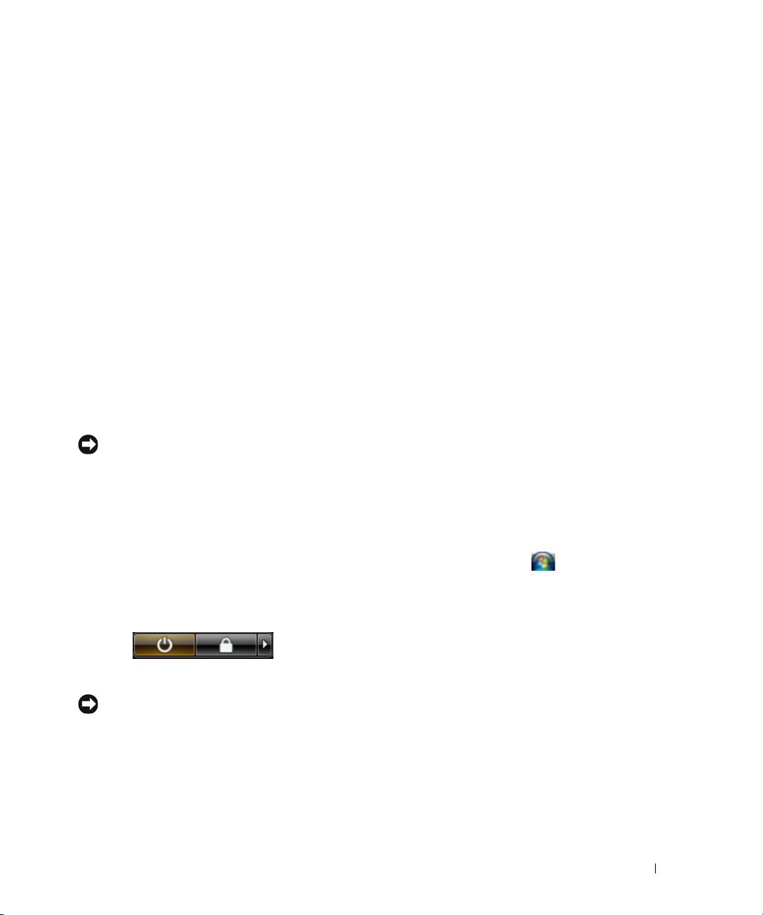
• How to remove and replace parts
• Specifications
• How to configure system settings
• How to troubleshoot and solve problems
• Service Tag and Express Service Code
• Microsoft Windows License Label
Dell™ OptiPlex™ User’s Guide
Microsoft Windows Help and Support Center
1
Click
Start
or
→
Help and Support→ Dell User
→
and System Guides
2
Click the
Service Tag and Microsoft® Windows® License
These labels are located on your computer.
• Use the Service Tag to identify your computer when you
use
• Enter the Express Service Code to direct your call when
contacting support.
User’s Guide
support.dell.com
System Guides
for your computer.
or contact support.
.
NOTE: As an increased security measure, the newly
designed Microsoft Windows license label incorporates a
missing portion or "hole" to discourage removal of the label.
18 Finding Information
Page 19

What Are You Looking For? Find It Here
• Solutions — Troubleshooting hints and tips, articles
from technicians, and online courses, frequently asked
questions
Dell Support Website — support.dell.com
NOTE: Select your region or business segment to view the
appropriate support site.
• Community — Online discussion with other Dell
customers
• Upgrades — Upgrade information for components, such
as memory, the hard drive, and the operating system
• Customer Care — Contact information, service call and
order status, warranty, and repair information
• Service and support — Service call status and support
history, service contract, online discussions with
technical support
• Dell Technical Update Service — Proactive e-mail
notification of software and hardware updates for your
computer
• Reference — Computer documentation, details on my
computer configuration, product specifications, and
white papers
• Downloads — Certified drivers, patches, and software
updates
• Desktop System Software (DSS)— If you reinstall the
operating system for your computer, you should also
reinstall the DSS utility. DSS provides critical updates
for your operating system and support for processors,
optical drives, USB devices, and so on. DSS is necessary
for correct operation of your Dell computer. The
software automatically detects your computer and
To download Desktop System Software:
1
Go to
segment, and enter your Service Tag.
2
Select
3
Click your operating system and search for the keyword
Desktop System Software
NOTE: The support.dell.com user interface may vary
depending on your selections.
operating system and installs the updates appropriate
for your configuration.
• How to use Windows XP
• How to work with programs and files
• How to personalize my desktop
Windows Help and Support
1
To access Windows Help and Support:
• In Windows XP, click
• In Windows Vista
button
2
Type a word or phrase that describes your problem, and
then click the arrow icon.
3
Click the topic that describes your problem.
4
Follow the instructions on the screen.
support.dell.com
, select your region or business
Drivers & Downloads
.
Start and click
®
, click the Windows Vista Start
and click
Help and Support
and click Go.
Help and Support
.
.
Finding Information 19
Page 20

What Are You Looking For? Find It Here
• How to reinstall my operating system
Operating System Media
NOTE: The Operating System media may be optional and may
not ship with your computer.
The operating system is already installed on your computer.
To reinstall your operating system, use the Operating
System media. See "Reinstalling Windows XP or Windows
Vista" on page 363.
NOTE: The color of your media varies based on the operating
system you ordered.
After you reinstall your
operating system, use the
Drivers and Utilities media
to reinstall drivers for the
devices that came with
your computer.
Your operating system
product key label is located
on your computer.
20 Finding Information
Page 21
Before You Begin
This chapter provides procedures for removing and installing the components in your computer. Unless
otherwise noted, each procedure assumes that the following conditions exist:
• You have performed the steps in "Turning Off Your Computer" on page 21 and "Before Working Inside
Your Computer" on page 21.
• You have read the safety information in your Dell™
• A component can be replaced by performing the removal procedure in reverse order.
Recommended Tools
The procedures in this document may require the following tools:
• Small flat-blade screwdriver
• Phillips screwdriver
• Flash BIOS update program floppy disk or CD
Turning Off Your Computer
NOTICE: To avoid losing data, save and close all open files and exit all open programs before you turn off your
computer.
1
Shut down the operating system:
a
Save and close all open files and exit all open programs.
b
In the Microsoft® Windows® XP operating system
Product Information Guide.
, click
Start→
Shut Down→
Shut down
.
In Microsoft Windows Vista®,
corner of the desktop, click the arrow in the lower-right corner of the Start menu as shown below,
and then click
The computer turns off after the operating system shutdown process is complete.
NOTICE: Ensure that the computer and all attached devices are turned off. If your computer and attached devices
did not automatically turn off when you shut down your operating system, press and hold the power button for
about 4 seconds to turn them off.
Shut Down
click the Windows Vista Start button™, , in the lower-left
.
Before Working Inside Your Computer
Use the following safety guidelines to help protect your computer from potential damage and to help
ensure your own personal safety.
Before You Begin 21
Page 22

CAUTION: Before you begin any of the procedures in this section, follow the safety instructions in the Product
Information Guide.
CAUTION: Handle components and cards with care. Do not touch the components or contacts on a card. Hold a
card by its edges or by its metal mounting bracket. Hold a component such as a processor by its edges, not by its
pins.
NOTICE: Many repairs may only be done by a certified service technician. You should only perform
troubleshooting and simple repairs as authorized in your product documentation, or as directed by the online or
telephone service and support team. Damage due to servicing that is not authorized by Dell is not covered by your
warranty. Read and follow the safety instructions that came with the product.
NOTICE: When you disconnect a cable, pull on its connector or on its strain-relief loop, not on the cable itself.
Some cables have a connector with locking tabs; if you are disconnecting this type of cable, press in on the locking
tabs before you disconnect the cable. As you pull connectors apart, keep them evenly aligned to avoid bending any
connector pins. Also, before you connect a cable, ensure that both connectors are correctly oriented and aligned.
NOTICE: To avoid damaging the computer, perform the following steps before you begin working inside the
computer.
1
Turn off your computer.
NOTICE: To disconnect a network cable, first unplug the cable from your computer and then unplug it from the
network wall jack.
2
Disconnect any telephone or telecommunication lines from the computer.
3
Disconnect your computer and all attached devices from their electrical outlets, and then press the
power button to ground the system board.
4
If applicable, remove the computer stand (for instructions, see the documentation that came with the
stand) and the cable cover, if attached (see "Cable Cover (Optional)" on page 237).
CAUTION: To guard against electrical shock, always unplug your computer from the electrical outlet before
removing the cover.
5
Remove the computer cover.
• For a mini tower computer, see "Removing the Computer Cover" on page 27.
• For a desktop computer, see "Removing the Computer Cover" on page 90.
• For a small form factor computer, see "Removing the Computer Cover" on page 168.
• For an ultra small form factor computer, see "Removing the Computer Cover" on page 232.
NOTICE: Before touching anything inside your computer, ground yourself by touching an unpainted metal surface,
such as the metal at the back of the computer. While you work, periodically touch an unpainted metal surface to
dissipate any static electricity that could harm internal components.
22 Before You Begin
Page 23
Mini Tower Computer
3
11
10
6
7
2
8
5
4
1
9
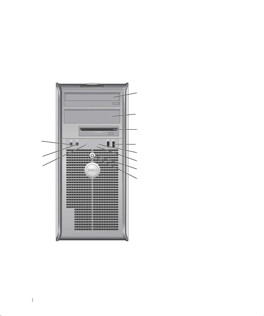
About Your Mini Tower Computer
Front View
23 Mini Tower Computer
Page 24

1 5.25-inch drive bay Can contain an optical drive. Insert a CD or DVD (if supported) into this drive.
2 5.25-inch drive bay Can contain an optical drive. Insert a CD or DVD (if supported) into this drive.
3 3.5-inch drive bay Can contain an optional floppy drive or optional media card reader.
4 USB 2.0 connectors (2) Use the front USB connectors for devices that you connect occasionally, such as
joysticks or cameras, or for bootable USB devices (see your online User’s Guide for
more information on booting to a USB device).
It is recommended that you use the back USB connectors for devices that typically
remain connected, such as printers and keyboards.
5 LAN indicator light This light indicates that a LAN (local area network) connection is established.
6 diagnostic lights Use the lights to help you troubleshoot a computer problem based on the diagnostic
code. For more information, see "Diagnostic Lights" on page 347.
7 power button Press this button to turn on the computer.
NOTICE: To avoid losing data, do not turn off the computer by pressing the power
button. Instead, perform an operating system shutdown. See "Before You Begin" on
page 21 for more information.
NOTICE: If your operating system has ACPI enabled, when you press the power
button the computer will perform an operating system shutdown.
8 power light The power light illuminates and blinks or remains solid to indicate different operating
modes:
• No light — The computer is turned off.
• Steady green — The computer is in a normal operating state.
• Blinking green — The computer is in a power-saving mode.
• Blinking or solid amber — The computer is receiving electrical power, but an internal
power problem may exist (see "Power Problems" on page 339).
To exit from a power-saving mode, press the power button or use the keyboard or the
mouse if it is configured as a wake device in the Windows Device Manager. For more
information about sleep modes and power-saving mode, see "Advanced Features" on
page 269.
See "Diagnostic Lights" on page 347 for a description of light codes that can help you
troubleshoot problems with your computer.
9 hard drive activity light This light flickers when the hard drive is being accessed.
10 headphone connector Use the headphone connector to attach headphones and most kinds of speakers.
11 microphone connector Use the microphone connector to attach a microphone.
24 Mini Tower Computer
Page 25
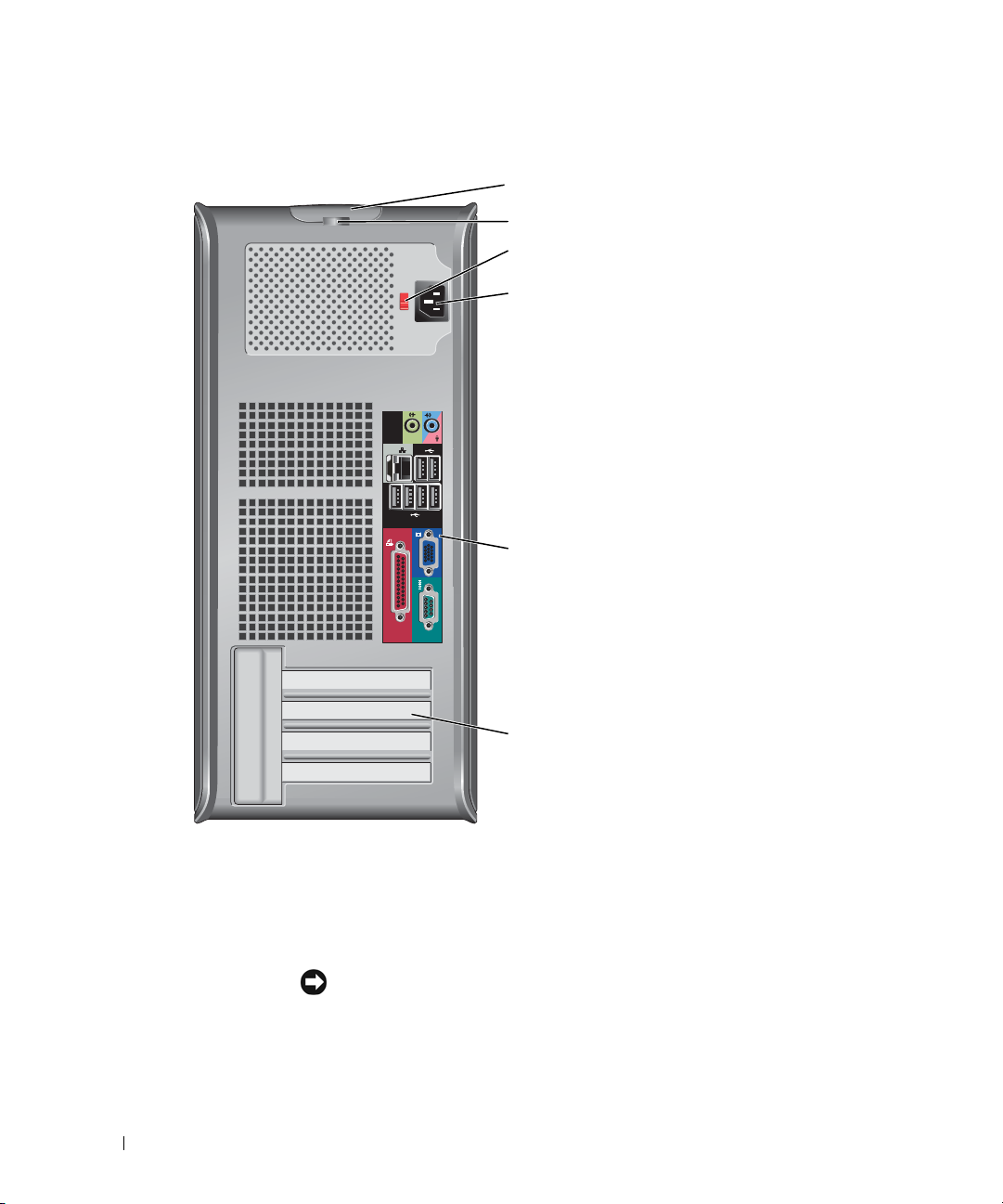
Back View
4
3
5
6
2
1
1 cover-release latch This latch allows you to open the computer cover.
2 padlock ring Insert a padlock to lock the computer cover.
3 voltage selection switch Your computer is equipped with a manual voltage-selection switch. To help avoid
damaging a computer with a manual voltage-selection switch, set the switch for the
voltage that most closely matches the AC power available in your location.
NOTICE: In Japan, the voltage selection switch must be set to the 115-V position.
Also, ensure that your monitor and attached devices are electrically rated to operate
with the AC power available in your location.
25 Mini Tower Computer
Page 26
4 power connector Insert the power cable.
13
98 7
5
6
24
5 back panel connectors Plug serial, USB, and other devices into the appropriate connectors. See "Back Panel
Connectors" on page 26.
6 card slots (4) Access connectors for any installed PCI or PCI Express cards, PS/2 connector, eSATA
connector, etc.
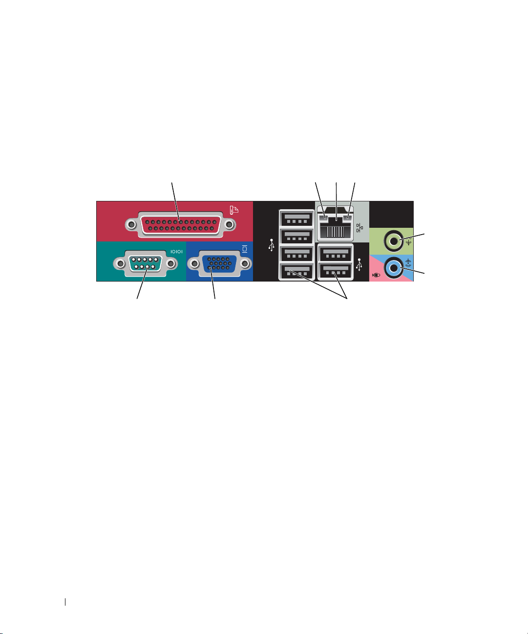
Back Panel Connectors
1 parallel connector Connect a parallel device, such as a printer, to the parallel connector. If you have a
USB printer, plug it into a USB connector.
NOTE: The integrated parallel connector is automatically disabled if the computer
detects an installed card containing a parallel connector configured to the same
address. For more information, see "System Setup Options" on page 281.
2 link integrity light
• Green — A good connection exists between a 10-Mbps network and the
computer.
• Orange — A good connection exists between a 100-Mbps network and the
computer.
• Yellow — A good connection exists between a 1-Gbps (or 1000-Mbps) network
and the computer.
• Off — The computer is not detecting a physical connection to the network.
26 Mini Tower Computer
Page 27

3 network adapter
connector
To attach your computer to a network or broadband device, connect one end of a
network cable to either a network jack or your network or broadband device.
Connect the other end of the network cable to the network adapter connector on
the back panel of your computer. A click indicates that the network cable has been
securely attached.
NOTE: Do not plug a telephone cable into the network connector.
For VPro to work, the network cable must be connected to the onboard NIC.
It is recommended that you use Category 5 wiring and connectors for your
network. If you must use Category 3 wiring, force the network speed to 10 Mbps to
ensure reliable operation.
4 network activity light Flashes a yellow light when the computer is transmitting or receiving network
data. A high volume of network traffic may make this light appear to be in a steady
"on" state.
5 line-out connector Use the green line-out connector to attach headphones and most speakers with
integrated amplifiers.
6 line-in/microphone
connector
7 USB 2.0 connectors (6) Use the back USB connectors for devices that typically remain connected, such as
8 video connector Plug the cable from your VGA-compatible monitor into the blue connector.
Use the blue and pink line-in/microphone connector to attach a record/playback
device such as a cassette player, CD player, or VCR.; or a personal computer
microphone for voice or musical input into a sound or telephony program.
printers and keyboards.
NOTE: If you purchased an optional graphics card, this connector will be covered by
a cap. Connect your monitor to the connector on the graphics card. Do not remove
the cap.
NOTE: If you are using a graphics card that supports dual monitors, use the y-cable
that came with your computer.
9 serial connector Connect a serial device, such as a handheld device, to the serial port. The default
designations are COM1 for serial connector 1 and COM2 for serial connector 2.
For more information, see "System Setup Options" on page 281.
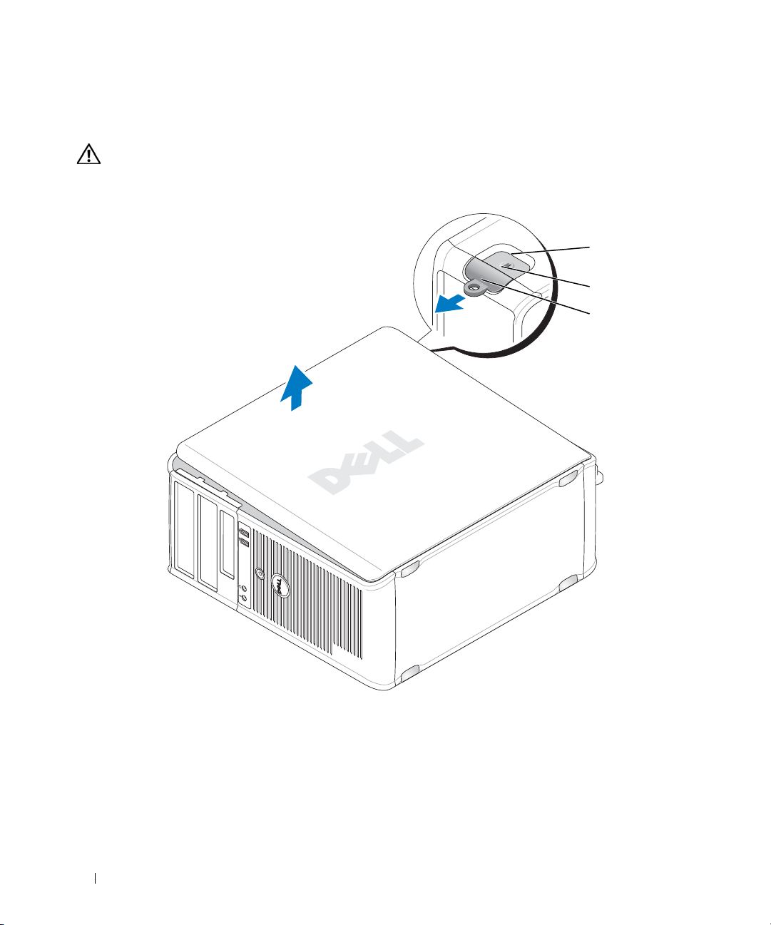
Removing the Computer Cover
CAUTION: Before you begin any of the procedures in this section, follow the safety instructions located in the
Product Information Guide.
CAUTION: To guard against electrical shock, always unplug your computer from the electrical outlet before
removing the computer cover.
1
Follow the procedures in "Before You Begin" on page 21.
2
Lay the computer on its side as shown in the illustration.
3
Locate the cover release latch shown in the illustration. Then, slide the release latch back as you lift the
cover.
27 Mini Tower Computer
Page 28
4
2
1
3
Grip the sides of the computer cover and pivot the cover up using the hinge tabs as leverage points.
5
Remove the cover from the hinge tabs and set it aside on a soft nonabrasive surface.
CAUTION: Graphics card heat sinks can become very hot during normal operation. Ensure that a graphics card
heat sink has had sufficient time to cool before you touch it.
1 security cable slot 2 cover release latch 3 padlock ring
28 Mini Tower Computer
Page 29
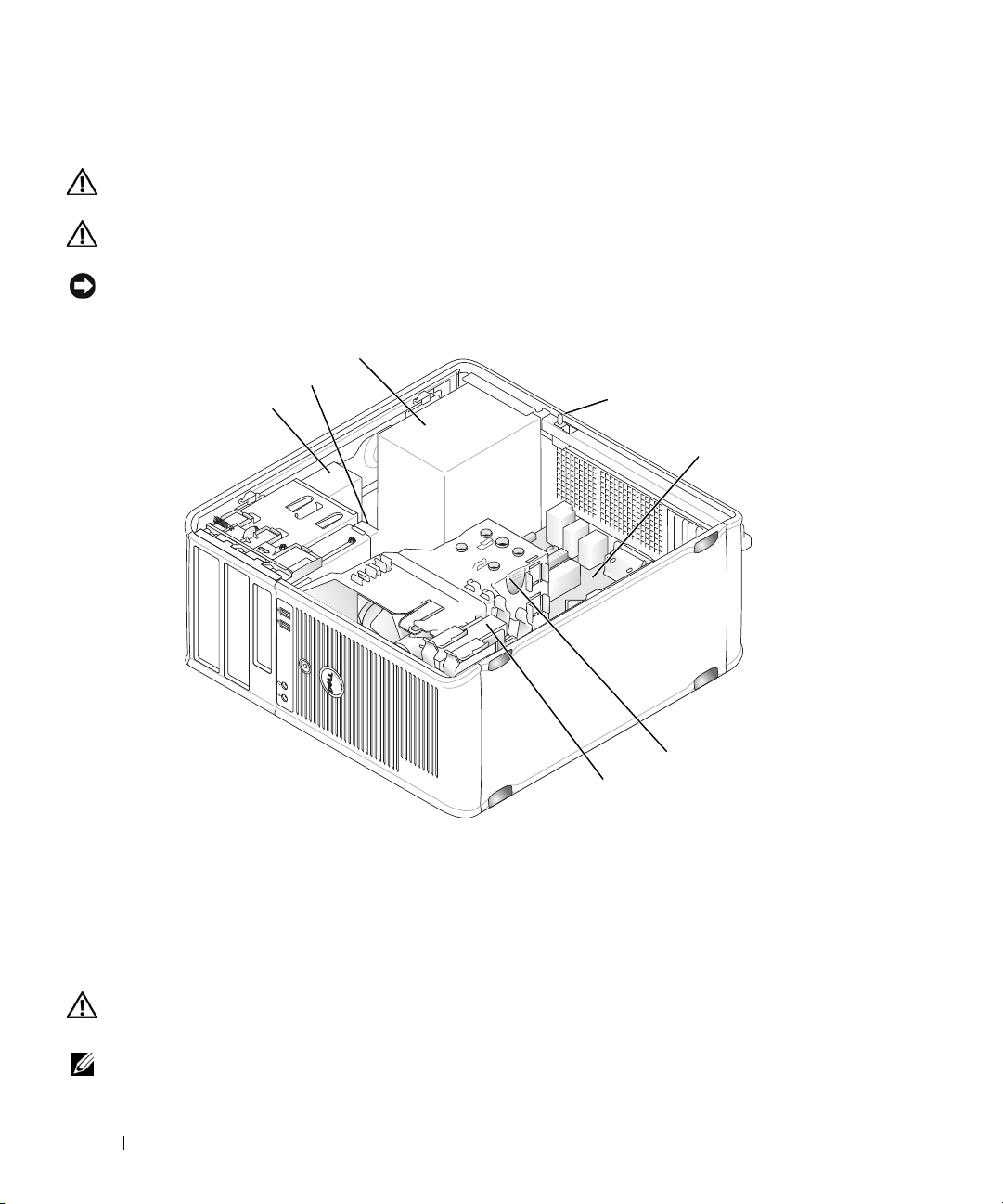
Inside Your Computer
1
3
5
4
7
2
6
CAUTION: Before you begin any of the procedures in this section, follow the safety instructions located in the
Product Information Guide.
CAUTION: To avoid electrical shock, always unplug your computer from the electrical outlet before removing
the computer cover.
NOTICE: Be careful when opening the computer cover to ensure that you do not accidentally disconnect cables
from the system board.
1 optical drive 2 disk drive 3 power supply
4 optional chassis-intrusion
switch
7 hard drive
5 system board 6 heat sink assembly
Chassis Intrusion Switch
CAUTION: Before you begin any of the procedures in this section, follow the safety instructions located in the
Product Information Guide.
NOTE: The chassis intrusion switch is standard on the ultra small form factor computer but is optional on mini
tower, desktop and small form factor computers; it may not be present on your computer.
29 Mini Tower Computer
Page 30
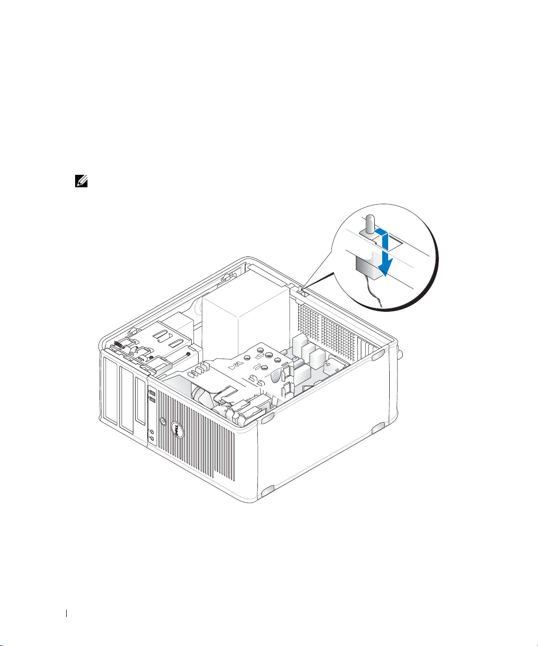
Removing the Chassis Intrusion Switch
1
Follow the procedures in "Before You Begin" on page 21.
2
Remove the computer cover (see "Removing the Computer Cover" on page 27).
3
Disconnect the chassis intrusion switch cable from the system board by using two fingers to squeeze
the release mechanism on one side of the connector as you pull to disconnect the cable connector.
4
Slide the chassis intrusion switch out of its slot in the metal bracket, and then push it down through
the square hole in the bracket to remove the switch and its attached cable from the computer.
NOTE: You may feel a slight resistance as you slide the switch out of the slot.
Replacing the Chassis Intrusion Switch
1
Gently insert the switch from underneath the metal bracket into the square hole in the bracket, and
then slide the chassis intrusion switch into its slot until you feel it snap securely into place.
2
Reconnect the cable to the system board.
3
Replace the computer cover (see "Replacing the Computer Cover" on page 317).
30 Mini Tower Computer
Page 31

Resetting the Chassis Intrusion Detector
1
Turn on (or restart) your computer.
2
When the blue DELL™ logo appears, press <F2> immediately.
If you wait too long and the operating system logo appears, continue to wait until you see the
Microsoft
3
Select the
the setting to
4
Save your BIOS settings and exit system setup.
®
Windows® desktop. Then shut down your computer and try again.
Chassis Intrusion
On, On-Silent
NOTE: The default setting is On-Silent.
option and then press the left- or right-arrow key to select
, or
Disabled
.
Reset
. Change
Mini Tower Computer 31
Page 32

System Board Components
2
3
5
7
16
8
17
18
9
10
4
13
11
22
21
19
1
15
14 12
20
6
1 speaker connector (INT_SPKR) 12 RTC reset jumper (RTCRST)
2 fan (FAN_CPU) 13 intrusion switch connector (INTRUDER)
3 processor connector (CPU) 14 battery socket (BATTERY)
4 processor power connector (12VPOWER) 15 PCI Express x16 connector (SLOT1)
5 memory module connectors (DIMM_1,
DIMM_2, DIMM_3, DIMM_4)
16 PCI Express x1 connector (SLOT4)
32 Mini Tower Computer
Page 33

6 password jumper (PSWD) 17 PCI connector (SLOT2)
7 SATA drive connectors (SATA0, SATA1, SATA2,
SATA3)
8 front-panel connector (FRONTPANEL) 19 serial connector (SERIAL2)
9 power connector (POWER) 20 system board speaker (BEEP)
10 external SATA connector (eSATA) 21 aux power LED (aux_LED)
11 internal USB (INT_USB) 22 floppy connector (DSKT)
18 PCI connector (SLOT3)
Mini Tower Computer 33
Page 34

34 Mini Tower Computer
Page 35

Mini Tower Computer Specifications
Microprocessor
Microprocessor type The following are supported:
•Intel® Core™2
• Intel vPro™
• Intel Celeron
Internal cache L1: up to 128 KB;
L2: up to 8 MB (depending on your processor)
Memory
Type 667-MHz or 800-MHz DDR2 SDRAM
Memory connectors 4
Memory modules supported 512-MB, 1-GB, or 2-GB non-ECC
Minimum memory dual-channel: 1 GB
single-channel: 512 MB
NOTE: 512 MB is the minimum shipping configuration.
Maximum memory 64-bit operating system: 8 GB
32-bit operating system: 4 GB
BIOS address F0000h
®
Computer Information
Chipset Intel Q35 Express Chipset w/ICH9DO
Data bus width 64 bits
Address bus width 32 bits
DMA channels eight
Interrupt levels 24
BIOS chip (NVRAM) 32 Mb
NIC integrated network interface with ASF 1.03 and 2.0 support as
defined by DMTF
Capable of 10/100/1000 communication
iAMT 3.0
Mini Tower Specifications 35
Page 36

Video
Type Intel Graphics Media Accelerator 3100 or DVI add-in card in PCI
Express x16 slot or PCI Express x16 graphics card
Audio
Type ADI 1984 High Definition Audio
Stereo conversion 24-bit analog-to-digital; 24-bit digital-to-analog
Controllers
Drives four SATA controllers and one eSATA controller supporting one
device each
Expansion Bus
Bus type PCI 2.3
PCI Express 1.0A
SATA 1.0A and 2.0
USB 2.0
Bus speed PCI: 133 MB/s
PCI Express x16: 8 GB/s bidirectional speed
PCI Express x1: 5 Gbps
SATA: 1.5 Gbps and 3.0 Gbps
USB: 480 Mbps
Cards: full-height cards supported
PCI:
connectors
connector size
connector data width
(maximum)
PCI Express:
connectors
power
connector size
connector data width
(maximum)
two
two 164 pin connectors
32 bits
one x1 and one x16
10 W (x1) and 75 W (x16) maximum
36 pins (x1) and 164 pins (x16)
one PCI Express lane (x1) and 16 PCI Express lanes (x16)
36 Mini Tower Specifications
Page 37

Drives
Internally accessible
• Two SATA (Serial ATA) hard drives
• One3.5-inch floppy drive or media reader
• Two SATA optical drives
Externally accessible One eSATA drive (optional)
Connectors
External connectors:
Serial
Parallel
Video
Network adapter
Optional PS/2 with secondary
9-pin connector; 16550C-compatible
25-pin connector (bidirectional)
15-pin VGA connector
RJ45 connector
two 6-pin mini-DINs
serial port adapter
USB
Audio
two front-panel and six back panel USB 2.0–compliant connectors
two connectors for line-in/ microphone and line-out; two frontpanel connectors for headphones and microphone
System board connectors:
SATA
eSATA
Floppy drive
Serial
Fan
PCI 2.2
PCI Express
Front panel
four 7-pin connectors
one 7-pin connector
34-pin connector
12-pin connector for optional second PS/2 serial port card
5-pin connector
three 120-pin connectors
one 120-pin (x16) connector
40-pin connector
Key Combinations
<Ctrl><Alt><Del> In Microsoft
window. If in MS-DOS
®
Windows® XP, brings up the Windows Security
®
mode, restarts (reboots) the computer.
<F2> or <Ctrl><Alt><Enter> starts embedded system setup (during start-up only)
<F3> automatically starts the computer from the network environment
specified by the remote boot environment (PXE) rather than from
one of the devices in the system setup Boot Sequence option
(during start-up only)
Mini Tower Specifications 37
Page 38

Key Combinations
<F12> or <Ctrl><Alt><F8> displays a boot device menu that allows the user to enter a device
for a single boot (during start-up only) as well as options to run
hard drive and system diagnostics
<Ctrl><p> displays the Management Engine BIOS Extension settings screen
that allows you to modify the settings
Controls and Lights
Power control push button
Power light green light — blinking green indicates sleep mode; solid green
indicates power-on state.
amber light — blinking amber indicates a problem with an
installed device; solid amber indicates an internal power problem
(See "Power Problems" on page 339.)
hard drive access light green
Link light (on front of chassis) solid green light indicates network connection
Link integrity light (on integrated
network adapter)
Activity light (on integrated network
adapter)
Diagnostic lights four lights on the front panel (See "Diagnostic Lights" on
Standby power light AUX_PWR on the system board
green light for 10-Mb operation; orange light for 100-Mb
operation; yellow light for a 1000-Mb (1-Gb) operation
yellow blinking light
page 347.)
Power
DC power supply:
Wattage
Heat dissipation
NOTE: Power consumption from an AC power source can be zero
when the computer is unplugged from that power source. However,
the computer draws a minute amount of power from the internal coin
cell battery even when the computer is not drawing power from the
AC power source.
305 W
1041 BTU/hr
NOTE: Heat dissipation is calculated based upon the power supply
rating.
Vo lt ag e
Backup battery 3-V CR2032 lithium coin cell
manual selection power supplies—90 to 135 V at 60 Hz; 180 to
265 V at 50 Hz
38 Mini Tower Specifications
Page 39

Physical
Height
Width
Depth
We ig ht
Environmental
Temperature:
Operating
Storage
Relative humidity 20% to 80% (noncondensing)
Maximum vibration:
Operating
Storage
Maximum shock:
Operating
Storage
Altitude:
Operating
Storage
Airborne contaminant level G2 or lower as defined by ISA-S71.04-1985
41.4 cm (16.3 inches)
18.5 cm (7.3 inches)
43.9 cm (17.3 inches)
12.34 kg (27.2 lb)
10° to 35°C (50° to 95°F)
–40° to 65°C (–40° to 149°F)
0.25 G at 3 to 200 Hz at 0.5 octave/min
0.5 G at 3 to 200 Hz at 1 octave/min
bottom half-sine pulse with a change in velocity of 50.8 cm/sec (20
inches/sec)
27-G faired square wave with a velocity change of 508 cm/sec (200
inches/sec)
–15.2 to 3048 m (–50 to 10,000 ft)
–15.2 to 10,668 m (–50 to 35,000 ft)
Mini Tower Specifications 39
Page 40

40 Mini Tower Specifications
Page 41

Cards
1
3
4
5
2
CAUTION: Before you begin any of the procedures in this section, follow the safety instructions located in the
Product Information Guide.
NOTICE: To prevent static damage to components inside your computer, discharge static electricity from your
body before you touch any of your computer’s electronic components. You can do so by touching an unpainted
metal surface on the computer chassis.
NOTE: Installing filler brackets over empty card-slot openings is necessary to maintain FCC certification of the
computer. The brackets keep dust and dirt out of your computer and maintains the airflow that cools your
computer.
Your Dell™ computer supports a PS/2 serial port adapter and provides the following connectors for PCI
and PCI Express cards:
• Two PCI card slots
• One PCI Express x16 card slot
• One PCI Express x1 card slot
1 PCI Express x16 card 4 PCI Express x1 card
2 securing tab (only for PCI
Express cards)
3 PCI Express x16 card slot
Installing a PCI or PCI Express Card
NOTE: Your Dell computer uses only PCI and PCI Express slots.
NOTE: The serial port adapter for your mini tower computer includes two PS/2 connectors.
5 PCI Express x1 card slot
Cards 41
Page 42

If you are replacing a card, uninstall the driver for the existing card. See the documentation that came
2
3
1
4
5
6
with the card for instructions.
Follow the procedures in "Before You Begin" on page 21.
1
2
Remove the computer cover (see "Removing the Computer Cover" on page 27).
3
Gently push the release tab on the card retention latch from the inside to pivot the latch open. The
latch will remain in the open position.
1 card retention latch 2 alignment guide 3 card
4 card-edge connector 5 card connector 6 release tab
4
If you are installing a new card, remove the filler bracket to create a card-slot opening. Then continue
with step 5.
5
If you are replacing a card that is already installed in the computer, remove the card. If necessary,
disconnect any cables connected to the card.
6
If your card includes a card retention bar, remove the bar. Gently pull the securing tab, grasp the card
by its top corners, and ease it out of its connector.
7
Prepare the new card for installation.
NOTE: See the documentation that came with the card for information on configuring the card, making internal
connections, or customizing it for your computer
42 Cards
Page 43

CAUTION: Some network adapters automatically start the computer when they are connected to a network. To
3
2
1
5
4
guard against electrical shock, be sure to unplug your computer from its electrical outlet before installing any
cards.
8
If you are installing the card into the x16 card connector, position the card so that the securing slot is
aligned with the securing tab, and gently pull the securing tab.
1 PCI Express x16 card 2 lever 3 securing slot (not all cards)
4 securing tab 5 PCI Express x16 card connector
9
Place the card in the connector and press down firmly. Ensure that the card is fully seated in the slot.
Cards 43
Page 44

1 card fully seated 2 card not fully seated
1
2
3
4
3 bracket within slot 4 bracket caught outside of slot
10
Before you lower the card retention mechanism, ensure that:
• The tops of all cards and filler brackets are flush with the alignment bar.
• The notch in the top of the card or filler bracket fits around the alignment guide.
11
Secure the card(s) by closing the card retention latch and snapping it into place.
NOTICE: Do not route card cables over or behind the cards. Cables routed over the cards can prevent the
computer cover from closing properly or cause damage to the equipment.
12
Connect any cables that should be attached to the card.
See the documentation for the card for information about the card’s cable connections.
13
Replace the computer cover (see "Replacing the Computer Cover" on page 317), reconnect the
computer and devices to electrical outlets, and then turn them on.
NOTICE: To connect a network cable, first plug the cable into the network wall jack and then plug it into the
computer.
44 Cards
Page 45

14
If you installed a sound card:
a
Enter system setup, select
Audio Controller
, and change the setting to
Off
(see "System
Setup" on page 280).
b
Connect external audio devices to the sound card’s connectors. Do not connect external
audio devices to the microphone, speaker/headphone, or line-in connectors on the back
panel of the computer.
15
If you installed an network adapter card and want to turn off the integrated network adapter:
a
Enter system setup, select
Network Controller
, and change the setting to
Off
"System Setup" on page 280).
b
Connect the network cable to the network adapter card’s connectors. Do not connect the
network cable to the integrated network connector on the back panel of the computer.
NOTICE: If you disable the integrated network adapter, you will not have AMT functionality.
16
Install any drivers required for the card as described in the card documentation.
Removing a PCI or PCI Express Card
1
Follow the procedures in "Before You Begin" on page 21.
2
Remove the computer cover (see "Removing the Computer Cover" on page 27).
3
Gently push the release tab on the card retention latch from the inside to pivot the latch
open. The latch will remain in the open position.
(see
Cards 45
Page 46

1 card retention latch 2 alignment guide 3 card
2
3
1
4
5
6
4 card-edge connector 5 card connector 6 release tab
4
If necessary, disconnect any cables connected to the card.
5
If you are removing the card permanently, install a filler bracket in the empty card-slot opening.
NOTE: Installing filler brackets over empty card-slot openings is necessary to maintain FCC certification of
the computer. The brackets keep dust and dirt out of your computer and maintains the airflow that cools your
6
computer.
NOTICE: To connect a network cable, first plug the cable into the network wall jack and then plug it into the
computer.
Replace the computer cover (see "Replacing the Computer Cover" on page 317), reconnect the
computer and devices to electrical outlets, and then turn them on.
7
Uninstall the card’s driver. See the documentation that came with the card for instructions.
8
If you removed a sound card:
a
Enter system setup, select
Audio Controller
, and change the setting to On (see "System Setup" on
page 280).
b
Connect external audio devices to the audio connectors on the back panel of the computer.
46 Cards
Page 47

9
2
1
If you removed a network-adapter card connector:
a
Enter system setup, select
Network Controller
, and change the setting to On (see "System Setup"
on page 280).
b
Connect the network cable to the integrated network connector on the back panel of the
computer.
PS/2 Serial Port Adapter
CAUTION: Before you begin any of the procedures in this section, follow the safety instructions located in the
Product Information Guide.
NOTICE: To prevent static damage to components inside your computer, discharge static electricity from your
body before you touch any of your computer's electronic components. You can do so by touching an unpainted
metal surface on the computer chassis.
Installing a PS/2 Serial Port Adapter
1
Follow the procedures in "Before You Begin" on page 21.
2
Remove the computer cover (see "Removing the Computer Cover" on page 27).
3
Gently push the release tab on the card retention latch from the inside to pivot the latch open. The
latch will remain in the open position
1 card retention latch 2 alignment guide
Cards 47
Page 48

4
1
2
3
4
Remove the filler bracket (if applicable).
NOTE: See the documentation that came with the PS/2 serial port adapter for information on configuring the
adapter, making internal connections, or customizing it for your computer.
5
Align the PS/2 serial-port adapter bracket in the retention slot and press down firmly. Ensure that the
adapter is fully seated in the slot.
1 card fully seated 2 card not fully seated
3 bracket within slot 4 bracket caught outside of slot
efore you close the card retention mechanism, ensure that:
B
• The tops of all adapters and filler brackets are flush with the alignment bar.
• The notch in the top of the adapter or filler bracket fits around the alignment guide.
6
Close the card retention latch and gently press until it snaps into place.
NOTICE: Do not route cables over any installed cards. Cables routed over the cards can prevent the computer
cover from closing properly or cause damage to the equipment.
7
Connect the adapter cable to the serial port adapter connector (SERIAL2) on the system board (see
"System Board Components" on page 32 for connector locations).
48 Cards
Page 49

NOTE: See the documentation for the PS/2 serial port adapter for information about the cable connections.
8
Replace the computer cover (see "Replacing the Computer Cover" on page 317).
Removing a PS/2 Serial Port Adapter
1
Follow the procedures in "Before You Begin" on page 21.
2
Remove the computer cover (see "Removing the Computer Cover" on page 27).
3
Gently push the release tab on the card retention latch from the inside to pivot the latch open. The
latch will remain in the open position.
Cards 49
Page 50

1 card retention latch 2 alignment guide
2
1
4
Disconnect the PS/2 serial adapter cable from the system board (see "System Board Components" on
page 32).
5
If necessary, disconnect any external cables connected to the adapter.
6
Ease the PS/2 serial-port adapter bracket out of its retention slot.
7
If you are removing the adapter permanently, install a filler bracket in the empty card-slot opening.
NOTE: Installing filler brackets over empty card-slot openings is necessary to maintain FCC certification of
the computer. The brackets also keep dust and dirt out of your computer and maintains the airflow that cools
your computer.
8
Before you close the card retention mechanism, ensure that:
• The tops of all cards and filler brackets are flush with the alignment bar.
• The notch in the top of the card or filler bracket fits around the alignment guide.
9
Secure the card(s) by closing the card retention latch and snapping it into place.
10
Replace the computer cover (see"Replacing the Computer Cover" on page 317).
50 Cards
Page 51

Installing eSATA
eSATA allows for full SATA data transfer rates (3 GB/sec) between a drive and the chipset, approximately
six times the data throughput of USB.
eSATA on your computer also supports hot-plugging. Hot-plugging allows for device detection without
powering down your computer prior to connecting the device to your computer. When a device is
connected, the operating system automatically recognizes the change. However, the computer must be
powered down before removal and/or replacement.
CAUTION: Before you begin any of the procedures in this section, follow the safety instructions located in the
Product Information Guide.
NOTE: To prevent static damage to components inside your computer, discharge static electricity from your body
before you touch any of your computer's electronic components. You can do so by touching an unpainted metal
surface on the computer chassis.
1
Remove the computer cover (see "Removing the Computer Cover" on page 27).
2
Remove the filler panel for the card slot you are using for the eSATA connector.
3
Mount the bracket into the desired card slot opening.
Cards 51
Page 52

4
Plug the free end of the eSATA cable into the eSATA connector on the system board.
5
Replace the computer cover (see "Replacing the Computer Cover" on page 317).
6
Boot your computer and enter system setup (see "Entering System Setup" on page 280). Use the
esata option to enable the esata drive.
52 Cards
Page 53

Drives
1
3
2
Your computer supports:
• Two SATA (Serial ATA) hard drives
• One 3.5-inch floppy drive or media card reader
• Two SATA optical drives
• One eSATA drive (with optional bracket)
1 optical drive 2 3.5-inch drive or media card
reader
3 hard drive
General Drive Installation Guidelines
SATA connectors on the system board are labeled SATA0, SATA1, SATA2, and SATA3.
Hard drives must be connected to the lower numbered SATA connectors, while any other SATA devices
(like an optical drive) must be connected to the remaining SATA connectors numbered higher than the
one that the hard drive(s) is connected to. For example, if you have two SATA hard drives and one SATA
optical drive, connect the two hard drives to the SATA0 and SATA1 connectors, and connect the SATA
optical drive to the SATA2 connector. (See "System Board Components" on page 32 for the location of
SATA connectors on the system board.)
Drives 53
Page 54

Connecting Drive Cables
1
2
1
2
When you install a drive, you connect two cables—a DC power cable and a data interface cable—to the
back of the drive.
Data Interface Connectors
SATA Connector
1 data interface cable connector 2 data interface connector
Power Cable Connectors
1 power cable 2 power input connector
54 Drives
Page 55

Connecting and Disconnecting Drive Cables
When removing a cable with a pull-tab, grasp the colored pull-tab and pull until the connector detaches.
When connecting and disconnecting a cable without a pull tab, hold the cable by the black connector at
each end.
Hard Drive
CAUTION: Before you begin any of the procedures in this section, follow the safety instructions in the Product
Information Guide.
CAUTION: To guard against electrical shock, always unplug your computer from the electrical outlet before
removing the computer cover.
NOTICE: To avoid damage to the drive, do not set it on a hard surface. Instead, set the drive on a surface, such as
a foam pad, that will sufficiently cushion it.
Removing a Hard Drive
1
If you are replacing a hard drive that contains data you want to keep, back up your files before you
begin this procedure.
2
Check the documentation for the drive to verify that it is configured for your computer.
3
Follow the procedures in "Before You Begin" on page 21.
4
Remove the computer cover (see "Removing the Computer Cover" on page 27).
5
Disconnect the power and data cables from the drive.
Drives 55
Page 56
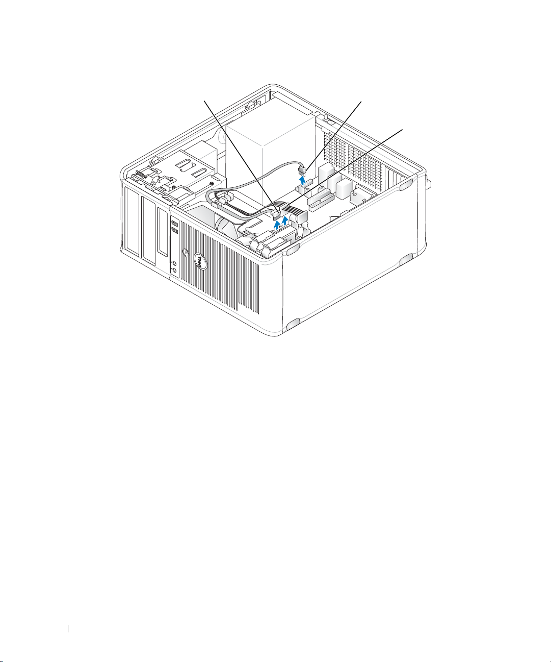
1 data cable 2 hard drive system board
3
2
1
connector
6
Press in on the blue release tabs on each side of the drive and slide the drive up and out of the
3 power cable
computer.
56 Drives
Page 57

1 hard drive 2 release tabs (2)
2
1
Installing a Hard Drive
1
Unpack the replacement hard drive, and prepare it for installation.
2
Check the documentation for the drive to verify that it is configured for your computer.
3
If your replacement hard drive does not have the plastic hard drive bracket attached, remove the
bracket from the existing drive by unsnapping it from the drive.
Drives 57
Page 58

1 hard drive 2 hard drive bracket
1
2
2
1
3
4
Snap the bracket onto the new drive.
1 hard drive 2 hard drive bracket 3 pins
58 Drives
Page 59

5
Gently spread the sides of the drive bracket and slide the hard drive into the bracket, aligning the drive
with the bracket pins, until the drive clicks into place.
6
Carefully slide the hard drive into the drive bay until it clicks into place.
7
Connect the power and data cables to the drive.
8
Ensure that the data cable is securely connected to the connector on the system board.
NOTICE: Always connect the data cable to the SATA0 connector on the system board, or to the SATA1 connector if
you already have a hard drive connected to the SATA0 connector and you are installing a second hard drive.
9
Check all connectors to be certain that they are properly cabled and firmly seated.
10
Replace the computer cover (see "Replacing the Computer Cover" on page 317).
11
Insert bootable media and enter system setup (see "System Setup" on page 280), and update the SATA
port option under the Drives option list.
12
Exit system setup, and reboot the computer.
13
Partition and logically format your drive.
See the documentation for your operating system for instructions.
14
Test the hard drive by running the Dell Diagnostics (see
"Dell Diagnostics
" on page 353).
Drives 59
Page 60

15
If the drive you just installed is the primary drive, install your operating system on the hard drive. If the
drive you just installed is the primary drive, insert a bootable medium into your boot drive. See the
documentation that came with the drive for instructions on installing any software required for drive
operation.
Adding a Second Hard Drive
CAUTION: Before you begin any of the procedures in this section, follow the safety instructions in the Product
Information Guide.
CAUTION: To guard against electrical shock, always unplug your computer from the electrical outlet before
removing the computer cover.
NOTICE: To avoid damage to the drive, do not set it on a hard surface. Instead, set the drive on a surface, such as
a foam pad, that will sufficiently cushion it.
NOTICE: If you are replacing a hard drive that contains data you want to keep, back up your files before you begin
this procedure.
1
Check the documentation for the drive to verify that it is configured for your computer.
2
Follow the procedures in "Before You Begin" on page 21.
3
Remove the computer cover (see "Removing the Computer Cover" on page 27).
4
Remove the plastic hard drive bracket from the inside of the hard drive bay by squeezing the release
tabs and gently pulling the bracket up and out of the bay.
5
Gently spread the sides of the drive bracket and slide the hard drive into the bracket, aligning the drive
with the bracket pins, until the drive clicks into place.
60 Drives
Page 61

1 hard drive 2 hard drive bracket 3 pins
2
1
3
6
Carefully slide the new hard drive into the bay until it clicks into place.
7
Connect the power cable to the drive.
Drives 61
Page 62

8
Locate an unused SATA connector on the system board and attach a data cable to this connector and
to the second hard drive.
62 Drives
Page 63

1 data cable 2 hard drive system board
3
2
1
connector
9
Replace the computer cover (see "Replacing the Computer Cover" on page 317).
10
Enter system setup (see "System Setup" on page 280), and update the SATA port option under the
Drives option list.
11
Exit system setup, and reboot the computer.
12
Partition and logically format your drive.
3 power cable
See the documentation for your operating system for instructions.
13
Test the hard drive by running the Dell Diagnostics (see
14
If the drive you just installed is the primary drive, install your operating system on the hard drive.
"Dell Diagnostics
" on page 353).
Floppy Drive
CAUTION: Before you begin any of the procedures in this section, follow the safety instructions located in the
Product Information Guide.
CAUTION: To guard against electrical shock, always unplug your computer from the electrical outlet before
removing the computer cover.
Drives 63
Page 64

Removing the Floppy Drive
1
2
1
Boot your computer and enter system setup (see "Entering System Setup" on page 280). Use the
Diskette Drive
2
Follow the procedures in "Before You Begin" on page 21.
3
Remove the computer cover (see "Removing the Computer Cover" on page 27).
4
Remove the drive panel by sliding the drive release latch downward to open the panel, and then
option to disable the floppy drive.
remove it from the hinges.
5
Disconnect the power and data cables from the back of the floppy drive.
1 floppy drive 2 drive release latch
6
Grasp the sliding plate lever and slide it towards the bottom of the computer until the drive panel
snaps open; while holding the lever in place, slide the drive out of the computer.
Installing the Floppy Drive
1
If you are replacing a floppy drive, remove the shoulder screws from the existing drive and attach the
screws to the replacement drive.
2
If you are installing a new floppy drive, remove the drive-panel insert for the 3.5-inch drive bay, remove
the shoulder screws from the inside of the drive-panel insert and attach the screws to the new drive.
64 Drives
Page 65

3
1
2
3
Align the shoulder screws on the floppy drive with the shoulder screw slots, and gently slide it into the
bay until it clicks into place.
4
Attach the power and data cables to the floppy drive and to the system board.
1 floppy drive 2 shoulder screws (4) 3 shoulder screw slots (2)
Drives 65
Page 66

1 data cable 2 power cable 3 floppy drive connector (DSKT)
1
2
3
5
Replace the computer cover (see "Replacing the Computer Cover" on page 317).
6
Enter system setup (see "Entering System Setup" on page 280), and use the
enable your new floppy drive.
7
Verify that your computer works correctly by running the Dell Diagnostics (see "Dell Diagnostics" on
Diskette Drive
page 353).
Media Card Reader
CAUTION: Before you begin any of the procedures in this section, follow the safety instructions located in the
Product Information Guide.
CAUTION: To guard against electrical shock, always unplug your computer from the electrical outlet before
removing the computer cover.
Removing the Media Card Reader
1
Follow the procedures in "Before You Begin" on page 21.
2
Remove the computer cover (see "Removing the Computer Cover" on page 27).
66 Drives
option to
Page 67
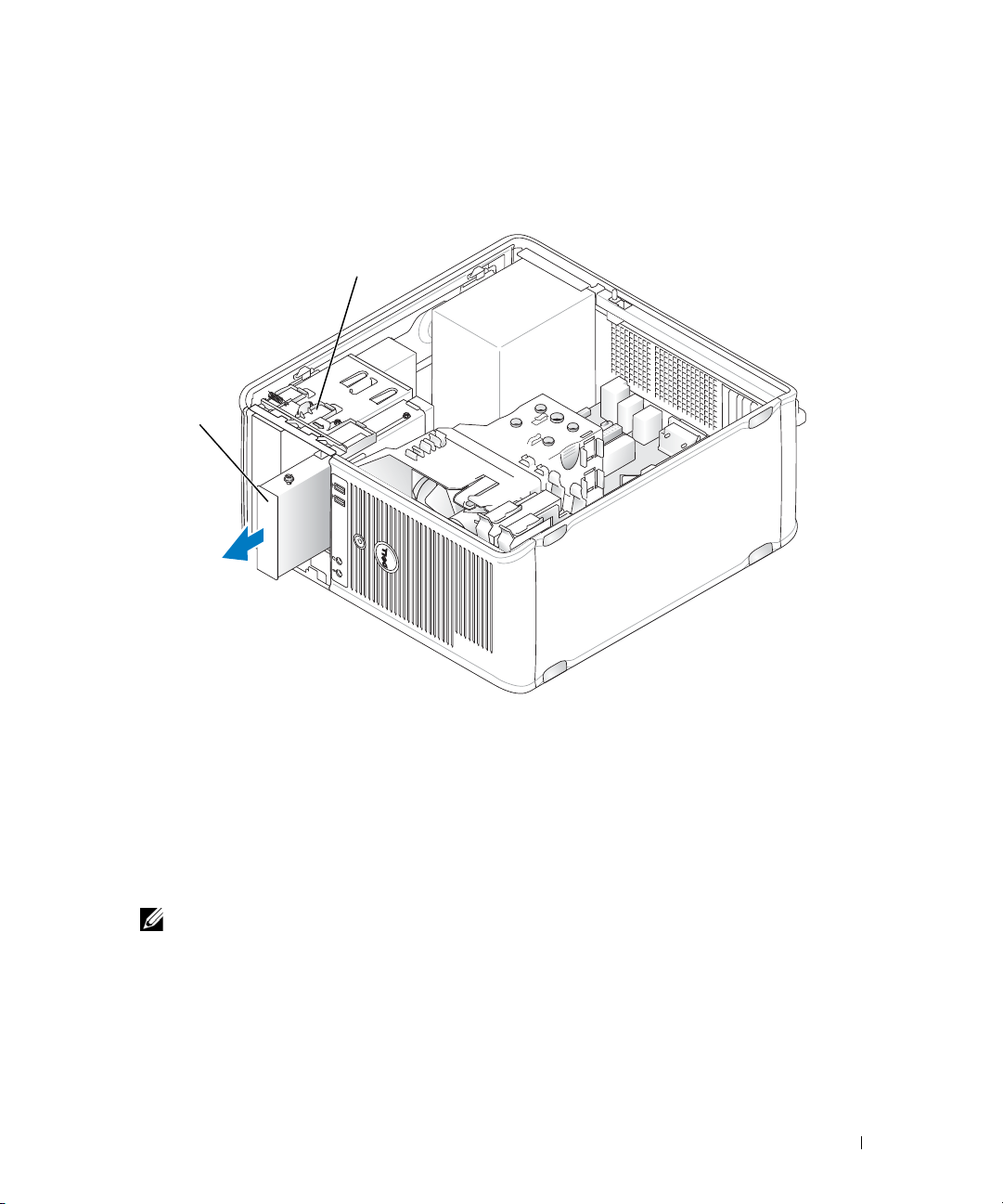
3
1
2
Remove the drive panel by sliding the drive release latch downward to open the panel, and then
remove it from the hinges.
4
Disconnect the cable from the back of the media card reader.
1 media card reader 2 drive release latch
5
Grasp the sliding plate lever and slide it towards the bottom of the computer until the drive panel
snaps open; while holding the lever in place, slide the media card reader out of the computer.
Installing the Media Card Reader
1
If you are replacing a media card reader, remove the shoulder screws from the existing drive and attach
the screws to the replacement media card reader.
NOTE: If you are replacing an existing floppy drive with a media card reader, ensure you disable the floppy
before installing the media card reader. Boot your computer and enter system setup (see "Entering System
Setup" on page 280). Use the Diskette Drive option to disable the floppy drive. Follow instructions in
"Removing the Floppy Drive" on page 64.
2
If you are installing a new media card reader, remove the drive-panel insert for the 3.5-inch drive bay,
remove the shoulder screws from the inside of the drive-panel insert and attach the screws to the new
drive.
Drives 67
Page 68

3
1
2
3
Align the shoulder screws on the media card reader with the shoulder screw slots, and gently slide it
into the bay until it clicks into place.
4
Attach the cable to the media card reader and to the system board.
1 media card
reader
2 shoulder screws (4) 3 shoulder screw slots (2)
68 Drives
Page 69
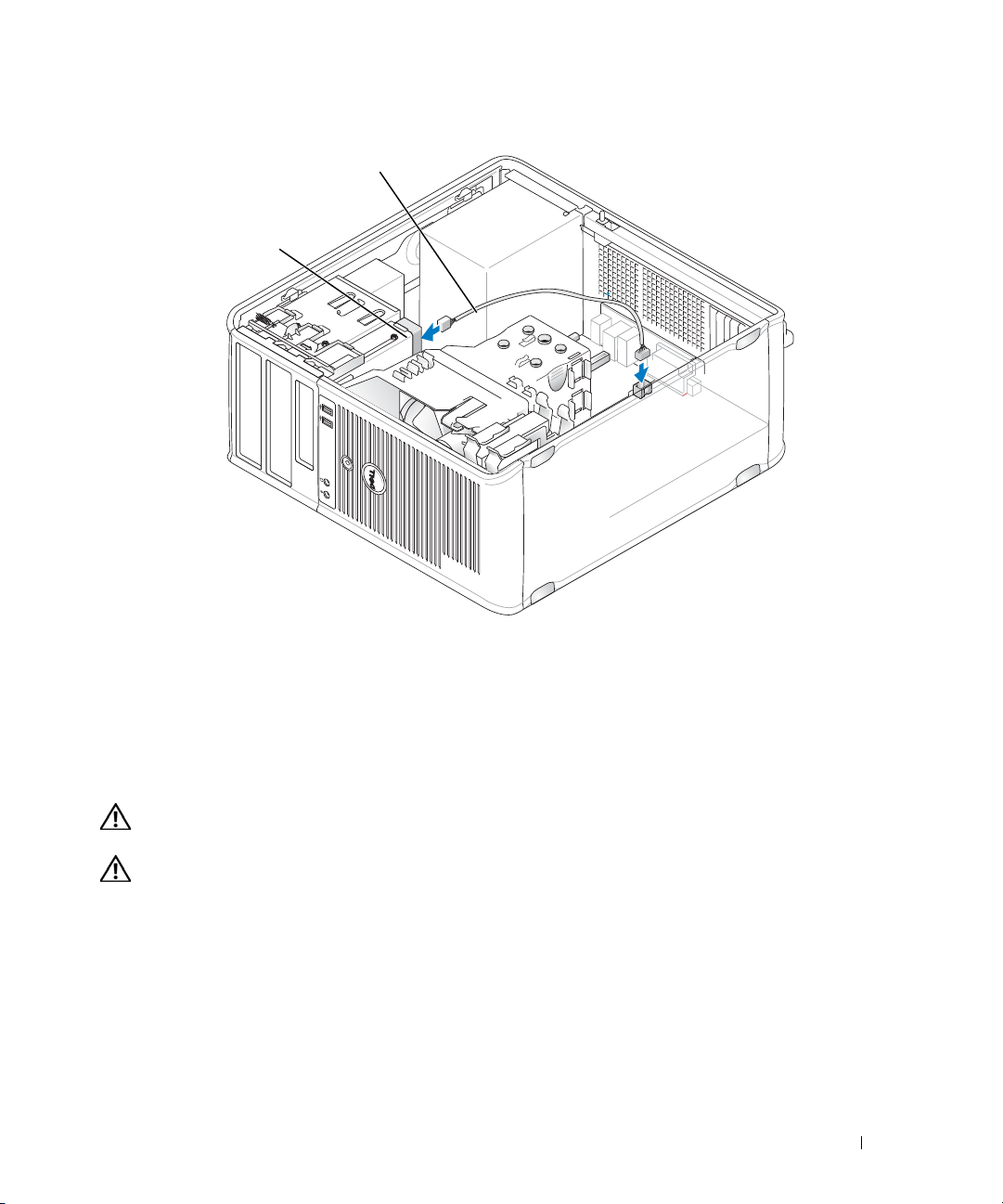
1 data/power cable 2 media card reader
1
2
5
Replace the computer cover (see "Replacing the Computer Cover" on page 317).
6
Verify that your computer works correctly by running the Dell Diagnostics (see "Dell Diagnostics" on
page 353).
Optical Drive
CAUTION: Before you begin any of the procedures in this section, follow the safety instructions located in the
Product Information Guide.
CAUTION: To guard against electrical shock, always unplug your computer from the electrical outlet before
replacing the cover.
Removing an Optical Drive
1
Follow the procedures in "Before You Begin" on page 21.
2
Remove the computer cover (see "Removing the Computer Cover" on page 27).
3
Disconnect the power and data cables from the back of the drive.
4
Grasp the sliding plate lever and slide it towards the bottom of the computer until the drive panel
snaps open; while holding the lever in place, slide the drive out of the computer.
Drives 69
Page 70

1 optical drive 2 drive release latch
1
2
Installing an Optical Drive
1
Follow the procedures in "Before You Begin" on page 21.
2
Remove the computer cover (see "Removing the Computer Cover" on page 27).
3
If you are replacing an optical drive, remove the shoulder screws from the existing drive and attach the
screws to the replacement drive.
4
If you are installing a new optical drive, remove the drive-panel insert, remove the shoulder screws from
the inside of the drive-panel insert, and attach the screws to the new drive.
70 Drives
Page 71

5
1
2
3
Check the documentation that accompanied the drive to verify that the drive is configured for your
computer.
6
Align the shoulder screws on the optical drive with the shoulder screw slots, and slide the drive into the
bay until it clicks into place.
1 optical drive 2 shoulder screws (3) 3 shoulder screw slots (2)
Drives 71
Page 72

7
1
2
3
Connect the power and data cables to the drive and to the system board.
NOTICE: Always connect the optical drive SATA cable to a system board SATA connector that is labeled with
a number higher than those connected to any hard drives installed in the computer.
8
Check all cable connections, and fold cables out of the way to provide airflow for the fan and cooling
vents.
9
Replace the computer cover (see "Replacing the Computer Cover" on page 317).
10
Update your configuration information in system setup by setting the appropriate
(SATA-1, SATA-2, or SATA-3) under
11
Verify that your computer works correctly by running the Dell Diagnostics (see "Dell Diagnostics" on
page 353).
72 Drives
1 power cable 2 data cable 3 SATA optical drive connector
Drive
Drives
. See "System Setup" on page 280.
option
Page 73

Processor
1
2
CAUTION: Before you begin any of the procedures in this section, follow the safety instructions located in the
Product Information Guide.
NOTICE: To prevent static damage to components inside your computer, discharge static electricity from your
body before you touch any of your computer’s electronic components. You can do so by touching an unpainted
metal surface on the computer chassis.
Removing the Processor
1
Follow the procedures in "Before You Begin" on page 21.
2
Remove the computer cover (see "Removing the Computer Cover" on page 27).
3
Move any cables routed over the heat sink assembly.
4
Loosen the captive screw (shown in the following figure) on each side of the heat sink assembly.
CAUTION: Despite having a plastic shield, the heat sink assembly may be very hot during normal operation. Be
sure that it has had sufficient time to cool before you touch it.
5
Rotate the heat sink assembly upward, and remove it from the computer.
Lay the heat sink down on its top, with the thermal grease facing upward.
1 heat sink assembly 2 captive screw housings (2)
Processor 73
Page 74

NOTICE: Unless a new heat sink is required for the new processor, reuse the original heat sink assembly when
2
3
4
5
1
you replace the processor.
6
Open the processor cover by sliding the release lever from under the center cover latch on the socket.
Then, pull the lever back to release the processor.
NOTICE: When replacing the processor, do not touch any of the pins inside the socket or allow any objects to fall
on the pins in the socket.
1 center cover latch 2 processor cover 3 processor
4 socket 5 release lever
7
Gently remove the processor from the socket.
Leave the release lever extended in the release position so that the socket is ready for the new
processor.
Installing the Processor
NOTICE: Ground yourself by touching an unpainted metal surface on the back of the computer.
NOTICE: When replacing the processor, do not touch any of the pins inside the socket or allow any objects to fall
on the pins in the socket.
1
Follow the procedures in "Before You Begin" on page 21.
2
Remove the computer cover (see "Removing the Computer Cover" on page 27).
74 Processor
Page 75

3
1
3
4
6
8
7
9
2
5
Unpack the new processor, being careful not to touch the underside of the processor.
NOTE: You must position the processor correctly in the socket to avoid permanent damage to the processor
and the computer when you turn on the computer.
4
If the release lever on the socket is not fully extended, move it to that position.
5
Orient the front and rear alignment-notches on the processor with the front and rear alignmentnotches on the socket.
6
Align the pin-1 corners of the processor and socket.
1 processor cover 2 tab 3 processor
4 processor socket 5 center cover latch 6 release lever
7 front alignment-notch 8 socket and processor pin-1 indicator 9 rear alignment-notch
NOTICE: To avoid damage, ensure that the processor aligns properly with the socket, and do not use excessive
force when you install the processor.
7
Set the processor lightly in the socket and ensure that the processor is positioned correctly.
8
When the processor is fully seated in the socket, close the processor cover.
Ensure that the tab on the processor cover is positioned underneath the center cover latch on the
socket.
Processor 75
Page 76

9
3
1
2
Pivot the socket release lever back toward the socket, and snap it into place to secure the processor.
10
Clean the thermal grease from the bottom of the heat sink.
NOTICE: Ensure that you apply new thermal grease. New thermal grease is critical for ensuring adequate thermal
bonding, which is a requirement for optimal processor operation.
11
Apply the new thermal grease to the top of the processor.
12
Install the heat sink assembly:
a
Place the heat sink assembly back onto the heat-sink assembly bracket.
b
Rotate the heat sink assembly down towards the computer base and tighten the two captive
screws.
NOTICE: Ensure that the heat sink assembly is correctly seated and secure.
1 heat sink assembly 2 heat-sink assembly bracket 3 captive screw housing (2)
13
Replace the computer cover (see "Replacing the Computer Cover" on page 317).
76 Processor
Page 77

I/O Panel
Removing the I/O Panel
CAUTION: Before you begin any of the procedures in this section, follow the safety instructions located in the
Product Information Guide.
CAUTION: To guard against electrical shock, always unplug your computer from the electrical outlet before
removing the cover.
NOTE: Note the routing of all cables as you remove them so that you can re-route them correctly when installing
the new I/O panel.
1
Follow the procedures in "Before You Begin" on page 21.
2
Remove the computer cover (see "Removing the Computer Cover" on page 27).
NOTICE: When sliding the I/O panel out of the computer, be extremely careful. Carelessness may result in damage
to the cable connectors and the cable routing clips.
3
Remove the screw that secures the I/O panel. Press the release button to slide the card away from the
front of the computer.
4
Disconnect all of the cables from the I/O panel, and remove the panel from the computer.
I/O Panel 77
Page 78

3
4
2
1
1 I/O panel release button 2 securing screw
3 I/O panel 4 I/O cable connector
Replacing the I/O Panel
1
To replace the I/O panel, follow the removal procedure in the reverse order.
NOTE: Use the guides on the I/O panel bracket to help position the I/O panel in place, and use the notch on
the I/O panel bracket to help seat the panel.
78 I/O Panel
Page 79

Power Supply
Replacing the Power Supply
CAUTION: Before you begin any of the procedures in this section, follow the safety instructions located in the
Product Information Guide.
NOTICE: To prevent static damage to components inside your computer, discharge static electricity from your
body before you touch any of your computer’s electronic components. You can do so by touching an unpainted
metal surface on the computer chassis.
1
Follow the procedures in "Before You Begin" on page 21.
2
Remove the computer cover (see "Removing the Computer Cover" on page 27).
3
Disconnect the DC power cables from the system board and the drives.
Note the routing of the DC power cables underneath the tabs in the computer chassis as you remove
them from the system board and drives. You must route these cables properly when you replace them
to prevent them from being pinched or crimped.
4
Remove the four screws that attach the power supply to the back of the computer chassis.
5
Press the release button located on the floor of the computer chassis.
Power Supply 79
Page 80

1 2 3
4
6
Slide the power supply toward the front of the computer by approximately 1 inch.
7
Lift the power supply up and out of the computer.
8
Slide the replacement power supply into place.
9
Replace the screws that secure the power supply to the back of the computer chassis.
10
Reconnect the DC power cables to the power supply.
11
Connect the AC power cable to the AC power connector.
12
Replace the computer cover (see "Replacing the Computer Cover" on page 317).
80 Power Supply
1 release button 2 power supply
3 screws (4) 4 AC power connector
Page 81

DC Power Connectors
13 14 15 16 17 18 19 20 21 22 23 24
1 2 3 4 5 6 7 8 9 10 11 12
DC Power Connector P1
Pin Number Signal name 18-AWG Wire
1 +3.3 VDC Orange
2 +3.3 VDC Orange
3GND Black
Power Supply 81
Page 82

Pin Number Signal name 18-AWG Wire
4 +5 VDC Red
5GND Black
6 +5 VDC Red
7GND Black
8 PS_PWRGOOD Gray
9 P5AUX Purple
10 V_12P0_DIG White
11 V_12P0_DIG White
12 +3.3 VDC Orange
13 +3.3VDC/SE* Orange
14 -12 VDC Blue
15 GND Black
16 PWR_PS_ON Green
17 GND Black
18 GND Black
19 GND Black
20 NC NC
21 +5 VDC Red
22 +5 VDC Red
82 Power Supply
Page 83

Pin Number Signal name 18-AWG Wire
3
1
4
2
23 +5 VDC Red
24 GND Black
*Optional wire. Use 22-AWG wire instead of 18-AWG
wire.
DC Power Connector P2
Pin Number Signal Name 18-AWG Wire
1GNDBlack
2GNDBlack
3 +12 VADC Yellow
4 +12 VADC Yellow
DC Power Connectors P3, P5, P8, and P9
Pin Number Signal name 18-AWG Wire
1 +3.3 VDC Orange
2GNDBlack
3+5 VDCRed
4GNDBlack
5 +12 VBDC White
Power Supply 83
Page 84

DC Power Connector P7
4 3 2 1
DC Power Connector P10
Pin Number Signal Name 22-AWG Wire
1+5 VDCRed
2 GND Black
3 GND Black
4 +12 VDC Yellow
Pin Number Signal name 18-AWG Wire
1 +12 VBDC White
2GNDBlack
3GNDBlack
84 Power Supply
4+5 VDCRed
Page 85

Speakers
Installing a Speaker
CAUTION: Before you begin any of the procedures in this section, follow the safety instructions located in the
Product Information Guide.
NOTICE: To prevent static damage to components inside your computer, discharge static electricity from your
body before you touch any of your computer’s electronic components. You can do so by touching an unpainted
metal surface on the computer chassis.
1
Follow the procedures in "Before You Begin" on page 21.
2
Remove the cover of your computer (see "Removing the Computer Cover" on page 27).
3
Insert the speaker into the chassis of the computer.
4
Connect the cables to the system board.
5
Replace the computer cover.
6
Turn on power to the computer.
Speakers 85
Page 86

Removing a Speaker
CAUTION: Before you begin any of the procedures in this section, follow the safety instructions located in the
Product Information Guide.
NOTICE: To prevent static damage to components inside your computer, discharge static electricity from your
body before you touch any of your computer’s electronic components. You can do so by touching an unpainted
metal surface on the computer chassis.
1
Follow the procedures in "Before You Begin" on page 21.
2
Remove the cover of your computer (see "Removing the Computer Cover" on page 27).
3
Disconnect the cables from the system board.
4
Remove the speaker from the chassis of the computer.
5
Replace the computer cover.
6
Turn on power to the computer.
86 Speakers
Page 87

Desktop Computer
89
3
514611 10
2
7
About Your Desktop Computer
Front View
1 USB 2.0 connectors (2) Use the front USB connectors for devices that you connect occasionally, such as
joysticks or cameras, or for bootable USB devices (see "System Setup" on page 280
for more information about booting to a USB device).
It is recommended that you use the back USB connectors for devices that typically
remain connected, such as printers and keyboards.
2 LAN indicator light This light indicates that a LAN (local area network) connection is established.
3 power button Press this button to turn on the computer.
NOTICE: To avoid losing data, do not turn off the computer by pressing the
power button. Instead, perform an operating system shutdown. See "Turning Off
Your Computer" on page 21 for more information.
NOTICE: If your operating system has ACPI enabled, when you press the
power button the computer will perform an operating system shutdown.
4 Dell badge This badge can be rotated to match the orientation of your computer. To rotate,
place fingers around the outside of the badge, press firmly, and turn the badge. You
can also rotate the badge using the slot provided near the bottom of the badge.
87 Desktop Computer
Page 88

5 power light The power light illuminates and blinks or remains solid to indicate different
5
1
2 3 4 6
operating states:
• No light — The computer is turned off.
• Steady green — The computer is in a normal operating state.
• Blinking green — The computer is in a power-saving mode.
• Blinking or solid amber — See "Power Problems" on page 339.
To exit from a power-saving mode, press the power button or use the keyboard or
the mouse if it is configured as a wake device in the Windows Device Manager. For
more information about sleep modes and exiting from a power-saving mode, see
"Power Management for Windows XP and Windows Vista
See "Diagnostic Lights" on page 347 for a description of light codes that can help
you troubleshoot problems with your computer.
6 diagnostic lights Use the lights to help you troubleshoot a computer problem based on the
diagnostic code. For more information, see "Diagnostic Lights" on page 347.
7 hard drive activity light This light flickers when the hard drive is being accessed.
8 headphone connector Use the headphone connector to attach headphones and most kinds of speakers.
9 microphone connector Use the microphone connector to attach a microphone.
10 3.5-inch drive bay Can contain an optional floppy drive, second hard drive, or optional media card
reader.
11 5.25-inch drive bay Can contain an optical drive. Insert a CD or DVD (if supported) into this drive.
" on page 292.
Back View
1 card slots Access connectors for any installed PCI or PCI Express cards, PS/2 connector,
eSATA connector, etc.
NOTE: The back view of the computer is different if a riser is installed.
2 back panel connectors Plug serial, USB, and other devices into the appropriate connectors (see "Back
Panel Connectors" on page 89).
3 power connector Insert the power cable.
88 Desktop Computer
Page 89

4 voltage selection switch Your computer is equipped with a manual voltage selection switch. To help avoid
13
98 7
5
6
24
damaging a computer with a manual voltage selection switch, set the switch for
the voltage that most closely matches the AC power available in your location.
NOTICE: In Japan, the voltage selection switch must be set to the 115-V
position.
Also, ensure that your monitor and attached devices are electrically rated to
operate with the AC power available in your location.
5 padlock ring Insert a padlock to lock the computer cover.
6 cover-release latch Allows you to open the computer cover.
Back Panel Connectors
1 parallel connector Connect a parallel device, such as a printer, to the parallel connector. If you have a
USB printer, plug it into a USB connector.
NOTE: The integrated parallel connector is automatically disabled if the computer
detects an installed card containing a parallel connector configured to the same
address. For more information, see "System Setup Options" on page 281.
2 link integrity light
• Green — A good connection exists between a 10-Mbps network and the
computer.
• Orange — A good connection exists between a 100-Mbps network and the
computer.
• Yellow — A good connection exists between a 1-Gbps (or 1000-Mbps) network
and the computer.
• Off — The computer is not detecting a physical connection to the network.
Desktop Computer 89
Page 90

3 network adapter
connector
To attach your computer to a network or broadband device, connect one end of a
network cable to either a network jack or your network or broadband device.
Connect the other end of the network cable to the network adapter connector on
the back panel of your computer. A click indicates that the network cable has been
securely attached.
NOTE: Do not plug a telephone cable into the network connector.
For VPro to work, the network cable must be connected to the onboard NIC.
It is recommended that you use Category 5 wiring and connectors for your
network. If you must use Category 3 wiring, force the network speed to 10 Mbps to
ensure reliable operation.
4 network activity light Flashes a yellow light when the computer is transmitting or receiving network
data. A high volume of network traffic may make this light appear to be in a steady
"on" state.
5 line-out connector Use the green line-out connector to attach headphones and most speakers with
integrated amplifiers.
6 line-in/microphone
connector
7 USB 2.0 connectors (6) Use the back USB connectors for devices that typically remain connected, such as
8 video connector Plug the cable from your VGA-compatible monitor into the blue connector.
Use the blue and pink line-in/microphone connector to attach a record/playback
device such as a cassette player, CD player, or VCR.; or a personal computer
microphone for voice or musical input into a sound or telephony program.
printers and keyboards.
NOTE: If you purchased an optional graphics card, this connector will be covered by
a cap. Connect your monitor to the connector on the graphics card. Do not remove
the cap.
NOTE: If you are using a graphics card that supports dual monitors, use the y-cable
that came with your computer.
9 serial connector Connect a serial device, such as a handheld device, to the serial port. The default
designations are COM1 for serial connector 1 and COM2 for serial connector 2.
For more information, see "System Setup Options" on page 281.
Removing the Computer Cover
CAUTION: Before you begin any of the procedures in this section, follow the safety instructions in the Product
Information Guide.
CAUTION: To guard against electrical shock, always unplug your computer from the electrical outlet before
removing the computer cover.
1
Follow the procedures in "Before You Begin" on page 21.
2
If you have installed a padlock through the padlock ring on the back panel, remove the padlock.
3
Locate the cover release latch shown in the illustration. Then, slide the release latch back as you lift the
cover.
90 Desktop Computer
Page 91

4
2
1
3
Grip the sides of the computer cover and pivot the cover up using the hinge tabs as leverage points.
5
Remove the cover from the hinge tabs and set it aside on a soft nonabrasive surface.
CAUTION: Graphics card heat sinks can become very hot during normal operation. Ensure that a graphics card
heat sink has had sufficient time to cool before you touch it.
1 security cable slot
2 cover release latch
3 padlock ring
Inside Your Computer
CAUTION: Before you begin any of the procedures in this section, follow the safety instructions in the Product
Information Guide.
CAUTION: To avoid electrical shock, always unplug your computer from the electrical outlet before removing
the computer cover.
Desktop Computer 91
Page 92

NOTICE: Be careful when opening the computer cover to ensure that you do not accidentally disconnect cables
1
2
4
5
3
6
7
from the system board.
1 drive bays (media card
reader or floppy drive,
optical drive and hard drive)
2 power supply 6 heat sink assembly
3 optional chassis-intrusion
switch
4 system board
Chassis Intrusion Switch
CAUTION: Before you begin any of the procedures in this section, follow the safety instructions located in the
Product Information Guide.
NOTE: The chassis intrusion switch is standard on the ultra small form factor computer but is optional on mini
tower, desktop, and small form factor computers; it may not be present on your computer.
Removing the Chassis Intrusion Switch
1
Follow the procedures in "Before You Begin" on page 21.
2
Remove the computer cover (see "Removing the Computer Cover" on page 90).
92 Desktop Computer
5 card slots
7 front I/O panel
Page 93

3
Disconnect the chassis intrusion switch cable from the system board by using two fingers to squeeze
the release mechanism on one side of the connector as you pull to disconnect the cable connector.
4
Slide the chassis intrusion switch out of its slot in the metal bracket, and then push it down through
the square hole in the bracket to remove the switch and its attached cable from the computer.
NOTE: You may feel a slight resistance as you slide the switch out of the slot.
Replacing the Chassis Intrusion Switch
1
Gently insert the switch from underneath the metal bracket into the square hole in the bracket, and
then slide the chassis intrusion switch into its slot until it snaps securely into place.
2
Reconnect the cable to the system board.
3
Replace the computer cover (see "Replacing the Computer Cover" on page 317).
Resetting the Chassis Intrusion Detector
1
Turn on (or restart) your computer.
2
When the blue DELL™ logo appears, press <F2> immediately.
If you wait too long and the operating system logo appears, continue to wait until you see the
Microsoft
®
Windows® desktop. Then shut down your computer and try again.
Desktop Computer 93
Page 94

3
1
2
Select the
the setting to
4
Save your BIOS settings and exit system setup.
Chassis Intrusion
On, On-Silent
NOTE: The default setting is On-Silent.
option and then press the left- or right-arrow key to select
, or
Disabled
Reset
.
Removing the Heat Sink Assembly
1
Loosen the captive screw on each side of the heat sink assembly.
CAUTION: Despite having a plastic shield, the heat sink assembly may be very hot during normal operation. Be
sure that it has had sufficient time to cool before you touch it.
2
Rotate the heat sink assembly upward, and remove the assembly from the computer.
Lay the heat sink down on its top.
. Change
94 Desktop Computer
1 heat sink assembly
2 captive screw housing (2)
Page 95

System Board Components
12
4
15
16
81112
3
18
20
17
22
14
6
5
91013
19
7
21
Desktop Computer 95
Page 96

1 internal speaker (INT_SPKR) 12 intrusion switch connector (INTRUDER)
2 processor connector (CPU) 13 battery socket (BATTERY)
3 processor power connector (12VPOWER) 14 PCI Express x16 connector (SLOT1)
4 memory module connectors (DIMM_1,
DIMM_2, DIMM_3, DIMM_4)
5 password jumper (PSWD) 16 PCI connector (SLOT3)
6 SATA connectors (SATA0, SATA1, SATA2) 17 riser connector (uses PCI-E port/SLOT1 and
7 front-panel connector (FRONTPANEL) 18 serial connector (SERIAL2)
8 power connector (POWER) 19 system board speaker (BEEP)
9 external SATA connector (eSATA) 20 aux power LED (aux_LED)
10 internal USB (INT_USB) 21 floppy connector (DSKT)
11 RTC reset jumper (RTCRST) 22 fan connector (FAN_CPU)
15 PCI connector (SLOT2)
PCI port/SLOT2)
96 Desktop Computer
Page 97

Desktop Computer Specifications
Microprocessor
Microprocessor type The following are supported:
•Intel® Core™2
• Intel vPro™
• Intel Celeron
Internal cache L1: up to 128 KB;
L2: up to 8 MB (depending on your processor)
Memory
Type 667-MHz or 800-MHz DDR2 SDRAM
Memory connectors 4
Memory modules supported 512 MB, 1 GB, or 2 GB non-ECC
Minimum memory dual-channel: 1 GB;
single-channel: 512 MB
NOTE: 512 MB is the minimum shipping configuration.
Maximum memory 64-bit operating system: 8 GB
32-bit operating system: 4 GB
BIOS address F0000h
®
Computer Information
Chipset Intel Q35 Express Chipset w/ICH9DO
Data bus width 64 bits
Address bus width 32 bits
DMA channels eight
Interrupt levels 24
BIOS chip (NVRAM) 32 Mb
NIC integrated network interface with ASF 1.03 and 2.0 support as
defined by DMTF
Capable of 10/100/1000 communication
iAMT 3.0
Desktop Computer Specifications 97
Page 98

Video
Ty p e
Audio
Type ADI 1984 High Definition Audio
Stereo conversion 24-bit analog-to-digital; 24-bit digital-to-analog
Controllers
Drives three SATA controllers and one eSATA controller supporting one
Expansion Bus
Bus type PCI 2.3
Bus speed PCI: 133 MB/s
Cards standard configuration supports low-profile cards only;
PCI: without riser-card cage
connectors
card size
connector size
connector data width
(maximum)
PCI Express: without riser-card
cage
connectors
card size
power
• Intel Graphics Media Accelerator 3100 (integrated on system
board)
• PCI Express x16 slot can support either a PCI Express graphics
card or a DVI graphics card (for dual-monitor support)
device each
PCI Express 1.0A
SATA 1.0A and 2.0
USB 2.0
PCI Express x16: 8 GB/s bidirectional speed
SATA: 1.5 Gbps and 3.0 Gbps
USB: 480 Mbps
with optional riser-card cage, computer supports half-length, fullheight cards. Full-height cards are supported in the 6.875-inch riser
card cage.
two
low profile
120 pins
32 bits
one x16
low profile
25 W (maximum)
98 Desktop Computer Specifications
Page 99

Expansion Bus
connector size
connector data width
(maximum)
PCI and PCI Express: with
optional, full-height PCI Express
riser-card cage, supporting both
low-profile and full-height cards
PCI
connectors
card size
connector size
connector data width
(maximum)
PCI Express
connectors
card size
power
connector size
connector data width
(maximum)
PCI only: with optional, full-height
PCI riser-card cage, supporting
both low-profile and full-height
cards
connectors
card size
connector size
connector data width
(maximum)
eSATA
164 pins (x16)
16 PCI Express lanes (x16)
two
one low-profile card and one full-height card
120 pins
32 bits
one x16
full-height
25 W maximum
164 pins (x16)
16 PCI Express lanes (x16)
three PCI
one low-profile card and two full-height cards
120 pins
32 bits
Desktop Computer Specifications 99
Page 100

Drives
Externally accessible one One eSATA drive (optional)
Internally accessible
Connectors
External connectors:
Serial
Parallel
Video
Network adapter
Optional PS/2 with secondary serial
port adapter
USB
Audio
System board connectors:
SATA
eSATA
Internal USB 10-pin header for optional media card reader (in 3.5-inch drive bay)
Floppy drive
Serial
Fan
PCI Express
PCI 2.3
Front panel
• two SATA (Serial ATA) hard drives
• one3.5-inch floppy drive or media card reader
• one SATA optical drive
9-pin connector; 16550C-compatible
25-pin connector (bidirectional)
15-pin VGA connector
RJ45 connector
two 6-pin mini-DINs
two front-panel and six back panel USB 2.0–compliant connectors
two connectors for line-in/ microphone and line-out; two frontpanel connectors for headphones and microphone
three 7-pin connectors
one 7-pin connector
34-pin connector
12-pin connector for optional secondary PS/2 serial port card
5-pin connector
one 120-pin (x16) connector
two 120-pin connectors
40-pin connector
100 Desktop Computer Specifications
 Loading...