

Page 1

MSTP
INTEROPERABILITY
™
OF THE DELL
POWERCONNECT
™
6200 SERIES
SWITCHES
WITH CISCO IOS OR CISCO
CA TOS BASED SWITCHES
THIS WHITE PAPER IS FOR INFORMATIONAL PURPOSES ONLY, AND MAY
CONTAIN TYPOGRAPHICAL ERRORS AND TECHNICAL INACCURACIES. THE
CONTENT IS PROVIDED AS IS, WITHOUT EXPRESS OR IMPLIED WARRANTIES OF
ANY KIND.
Dell and PowerConnect are trademarks of Dell Inc. Other trademarks and trade names
may be used in this document to refer to either the entities claiming the marks and
names or their products. Dell disclaims proprietary interest in the marks and names
of others.
©Copyright 2008 Dell Inc. All rights reserved. Reproduction in any manner whats oever
without the express written permission of Dell Inc. is strictly forbidden. For more
information, contact Dell.
Information in this document is subject to change without notice.
Page 2

CONTENTS
INTRODUCTION 3
IEEE 802.1S MULTIPLE SPANNING TREE PROTOCOL OVERVIEW 3
DELL POWERCONNECT 62XX MSTP FUNCTIONAL DESCRIPTION 3
ACTIVE TOPOLOGY ENFORCEMENT 5
CONTROL PACKET BEHAVIOR 6
MSTP CLI COMMANDS 6
OPERATION IN THE NETWORK 7
SAMPLE SETUP AND CONFIGURATIONS 9
CONFIGURING BRIDGE BrA (WEB INTERFACE) 10
CONFIGURING BRIDGE BrB 16
CONFIGURING BRIDGE BrC 16
CONFIGURING EDGE DEVICES 17
VIEWING THE MSTP STATUS 18
ADDITIONAL MSTP STATUS INFORMATION 19
ADDITIONAL INFORMATION AND SCALABILITY
WITH MORE REGIONS
VOICE VLAN CONFIGURATION 4
CLI CONFIGURATION 4
WEB CONFIGURATION 8
FIGURES
FIGURE 1: VID TO FID ALLOCATION 4
FIGURE 2: EXAMPLE FID TO MSTI ALLOCATION 5
FIGURE 3: EXAMPLE RESULTANT VID TO MSTI ALLOCATION 5
FIGURE 4: SMALL BRIDGED NETWORK 7
FIGURE 5: SINGLE STP TOPOLOGY 7
FIGURE 7: MULTIPLE MSTP REGIONS 24
FIGURE 8: MULTIPLE MSTP REGION INTERACTIONS 25
23
Page 3

MSTP INTEROPERABILITY OF THE DELL™ POWERCONNECT™ 6200 SERIES SWITCHES
WITH CISCO IOS AND CISCO CATOS-BASED SWITCHES
INTRODUCTION
This paper describes the Multiple Spanning Tree Protocol (MSTP) support for Dell PowerConnect
62xx devices, which include the PC6224, PC6248, PC6224P, PC6248P, PC6224F, and
M6220 switches. This document also explains how to configure PowerConnect 62xx switches
to interoperate and connect with Cisco IOS and CatOS based switches when using the MSTP
industry standards. MSTP is defined in the IEEE 802.1s specification.
This document addresses the following topics:
• MSTP and its support in Dell PowerConnect 62xx devices
• Network operation of MSTP with configuration help for both Dell PowerConnect
and Cisco switches (Cisco Cat 3750 is taken as reference)
IEEE 802.1S MULTIPLE SPANNING TREE PROTOCOL OVERVIEW
IEEE 802.1s MSTP supports multiple instances of Spanning Tree Protocol (STP) to
efficiently channel VLAN traffic over different interfaces. Each spanning tree instance
behaves in the manner specified in IEEE 802.1w (Rapid Spanning Tree) with slight
modifications in the operation b ut not the end result.
The difference between RSTP and traditional STP (IEEE 802.1d) is that RSTP can configure and
recognize full duplex connectivity and ports that are connected to end stations. This allows RSTP
to perform a rapid transition of the port to the “Forw ard ing” stat e a nd to su ppr ess Top o logy Cha nge
Notifications. These features are repr esented by the para meter s p oint topo int and edgeport.
MSTP is compatible with both RSTP and STP and behaves appropriately with STP and RSTP
bridges. You can configure an MSTP bridge to behave entirely as an RSTP bridge or an STP
bridge. This means that an IEEE 802.1s bridge also supports IEEE 802.1w and IEEE 802.1d.
DELL POWERCONNECT 62XX MSTP FUNCTIONAL DESCRIPTION
The MSTP algorithm and protocol provides simple and full connectivity for frames assigned to
any given VLAN throughout a bridged LAN comprising arbitrarily interconnected networking
devices, each operating MSTP, STP or RSTP. MSTP allows frames assigned to different
VLANs to follow separate paths, each based on an independent Multiple Spanning Tree
Instance (MSTI), within Multiple Spanning Tree (MST) Regions composed of LANs or MSTP
Bridges. These regions and the other bridges and LANs are connected into a single Common
Spanning Tree (CST). [IEEE DRAFT P802.1s/D13]
MSTP connects all bridges and LANs with a single Common and Internal Spanning Tree
(CIST). The CIST supports the automatic determination of each MST region, choosing its
maximum possible extent. The connectivity calculated for the CIST provides the CST for
interconnecting these regions, and an Internal Spanning Tree (IST) within each region. MSTP
ensures that frames with a given VLAN ID (VID) are assigned to one and only one of the
MSTIs or the IST within the region, that that assignment is consistent among all the networking
devices in the region, and that the stable connectivity of each MSTI and IST at the boundary of
the Region matches that of the CST. The stable active topology of the Bridged LAN with
respect to frames consistently classified as belonging to any given VLAN thus simply and fully
connects all LANs and networking devices throughout the network, though frames belonging to
different VLANs can take different paths within any region. [IEEE DRAFT P802.1s/D13]
All bridges, whether they use STP, RSTP or MSTP, send information in Configuration
Messages via BPDUs to assign Port Roles that determine each port’s participation in a fully
and simply connected active topology based on one or more spanning trees. The information
communicated is known as the spanning tree priority vector. The BPDU structure for each
protocol is different. An MSTP bridge transmits the appropriate BPDU depending on the
received type of BPDU from a particular port.
An MST region has one or more MSTP bridges with the same MST Configuration Identifier.
MSTI regions use the same MST instance, and all bridges in the region must be able to send
and receive MSTP BPDUs.
APRIL 2008
3
3
Page 4
MSTP INTEROPERABILITY OF THE DELL™ POWERCONNECT™ 6200 SERIES SWITCHES
WITH CISCO IOS AND CISCO CATOS-BASED SWITCHES
The MST Configuration Identifier consists of the following components:
• Configuration Identifier Format Selector – 1 byte value encoded as zero
• Configuration Name – 32 byte string
• Configuration Revision Level – 2 byte value
• Configuration Digest – 16 byte signature of type HMAC-MD5 created from the MST
Configuration Table (a VID to MSTID mapping)
As there are multiple instances of Spanning Tree, there is an MSTP state maintained on a
per-port, per-instance basis (or on a per-port, per-VLAN basis – as any VLAN can be in one
and only one MSTI or CIST). For example, port A can be forwarding for instance 1 while
discarding for instance 2.
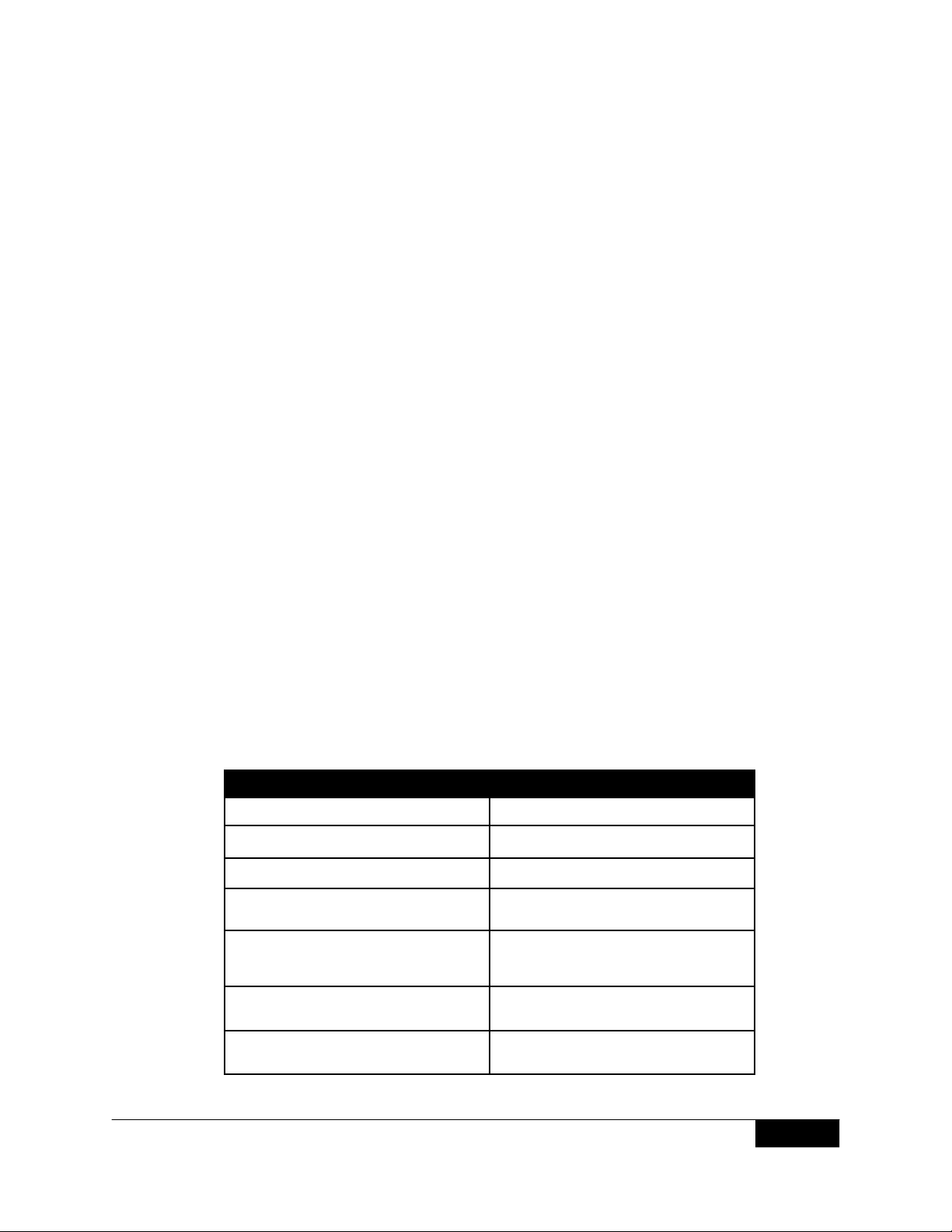
The port states have changed since the publication of the IEEE 802.1d specification. The
following table shows the port states for STP (802.1d) vs. MSTP (802.1s):
STP Port State
(IEEE 802.1d)
Disabled Disabled Discarding Excluded (Disabled)
Disabled Enabled Discarding Excluded (Disabled)
Blocking Excluded (Alternate, Backup)
Listening Included (Root, Designated)
Learning Included (Root, Designated)
Forwarding
In order to support multiple spanning trees, an MSTP bridge must be configur ed with an
unambiguous assignment of VIDs to spanning trees. This is achieved by:
Admin Port State
Enabled
Enabled
Enabled
Enabled
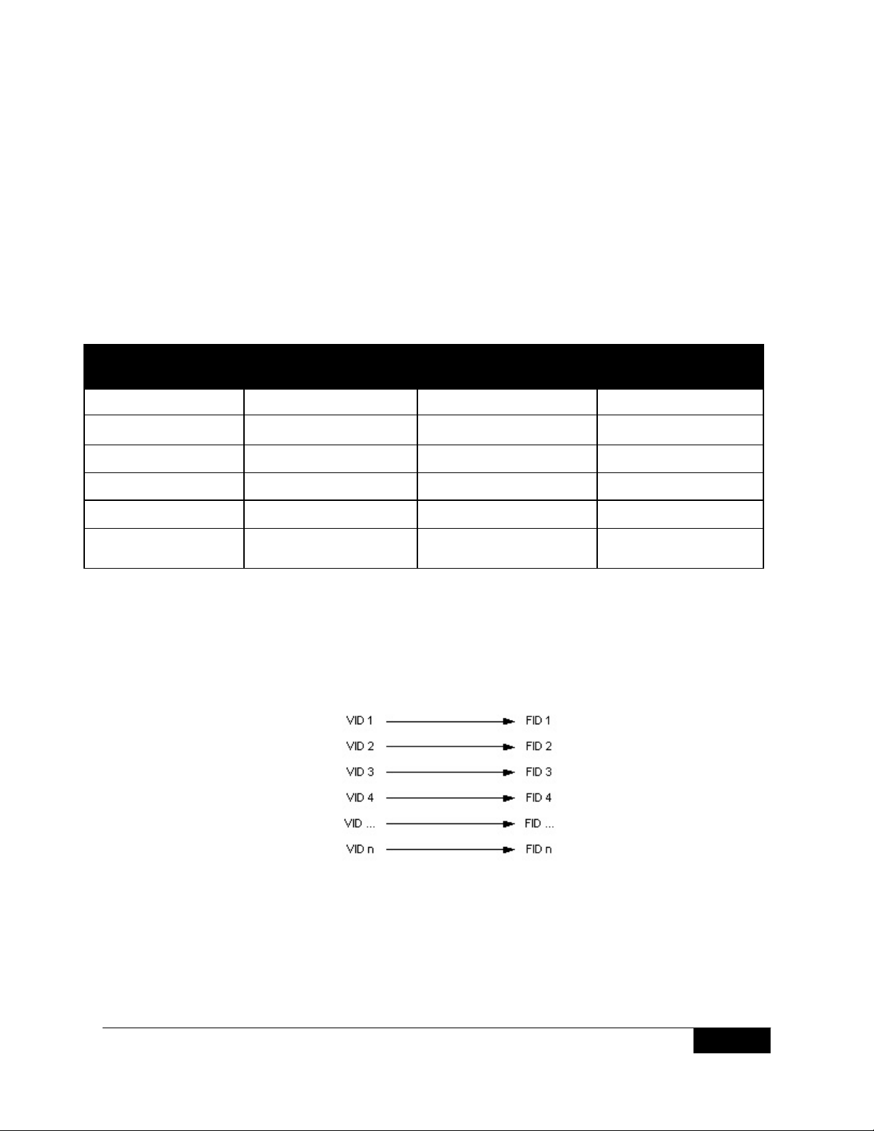
1. Ensuring that the allocation of VIDs to filtering IDs (FIDs) is unambiguous.
The Dell PowerConnect 62xx series switch implements this with a fixed VID to FID
assignment. Every VID is assigned to one and only one FID.
MSTP Port State
(IEEE 802.1s)
Discarding
Discarding
Learning
Forwarding
Active Topology
(Port Role)
Included
(Root, Designated, Master)
APRIL 2008
Figure 1: VID to FID Allocation
4
Page 5
MSTP INTEROPERABILITY OF THE DELL™ POWERCONNECT™ 6200 SERIES SWITCHES
WITH CISCO IOS AND CISCO CATOS-BASED SWITCHES
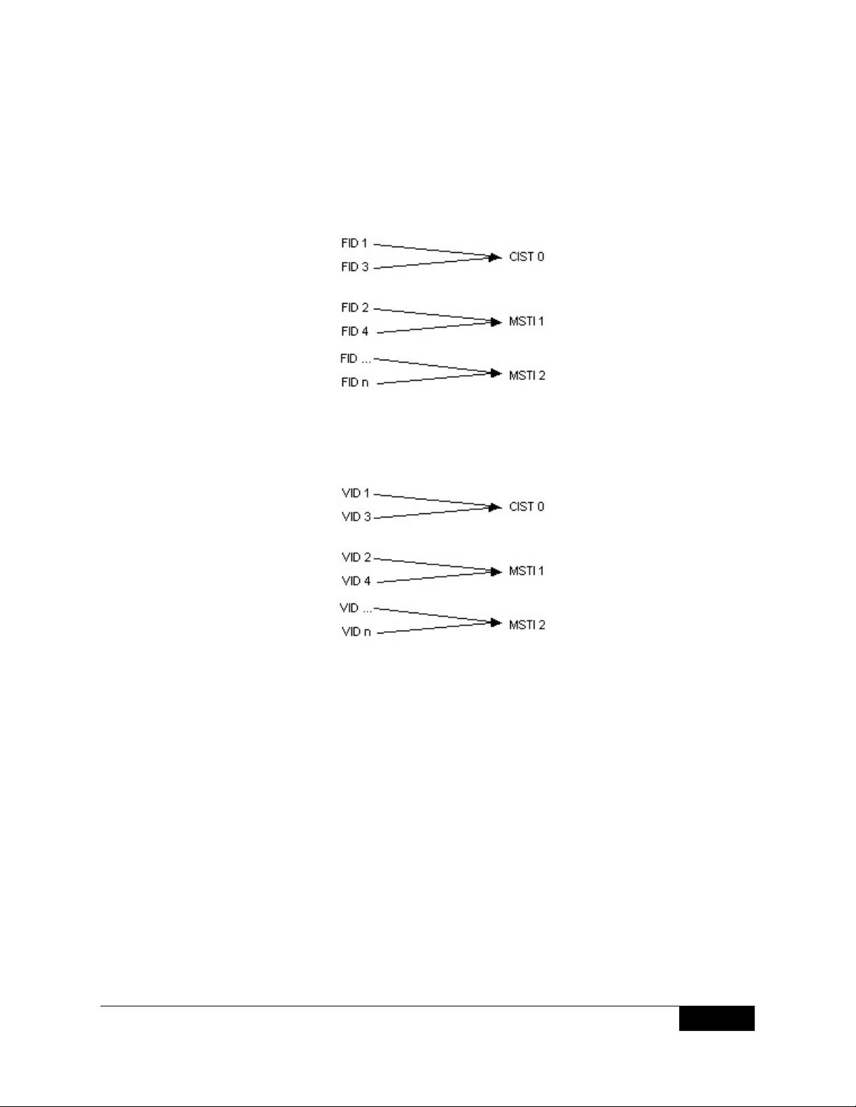
2. Ensuring that each FID supported by the Bridge is allocated to exactly one
The Dell PowerConnect 62xx series switch implements this through the FID to MSTI
Allocation Table. The following diagram shows an example configuration:
The combination of VID to FID and then FID to MSTI allocation defines a mapping of VIDs to
spanning tree instances, represented by the MST Configuration Table. The following diagram
shows an example configuration:
Spanning Tree Instance.
Figure 2: Example FID to MSTI Allocation
APRIL 2008
Figure 3: Example Resultant VID to MSTI Allocation
With this allocation, we ensure that every VLAN is assigned to one and only one MSTI. The
CIST is also an instance of spanning tree with an MSTID of 0. We can have an instance which
has no VIDs allocated to it but every VLAN must be allocated to one of the other instances of
spanning tree.
The portion of the active topology of the network that connects an y two bridges in the same
MST region traverses only MST bridges and LANs in that region and never bridges of an y
kind outside the region. In other words, connectivity within the region is independent of
external connectivity.
ACTIVE TOPOLOGY ENFORCEMENT
Each received frame is allocated to a spanning tree instance by the forwarding process using
the VID. The forwarding process selects each port as a potential transmission port if, and only
if all of the following conditions are met:
1. The port on which the frame was received is in forwarding mode for that spanning tree instance.
2. The port considered for transmission is in a forwarding state for that spanning tree instance.
3. The port considered for transmission is not the same port on which the frame was rece ived.
For each port not selected as a potential transmission port, the frame is discarded.
5
Page 6

MSTP INTEROPERABILITY OF THE DELL™ POWERCONNECT™ 6200 SERIES SWITCHES
WITH CISCO IOS AND CISCO CATOS-BASED SWITCHES
CONTROL PACKET BEHAVIOR
BPDU: Always transmitted as untagged. The port receives and transmits BPDUs in all three
MSTP states: Discarding, Learning and Forwarding. If MSTP is disabled for the device (manual
forwarding on all ports), BPDUs received are switched.
GVRP: Always transmitted as untagged. GVRP PDUs are received and transmitted only when
the port is in Forwarding state.
GMRP: GMRP PDUs are transmitted tagged or untagged as per the port’s tag setting. They
follow the ingress and egress rules.
LACPDU: LACP DUs are always transmitted untagged and a re received and transmitted in all
three MSTP states. These frames are never switched whether MSTP is enabled or not.
Pause Frames: Pause frames are never tagged or switched. The port receives and transmits
Pause frames in all three MSTP states. In other words, the STP state of the port has no
bearing on the transmission and reception of Pause Frames.
Other Frames to and from the CPU: All other frames are received and transmitted only if the
port is in Forwarding state.
All BPDUs (ST, TCN, RST, MST, etc.) use the unique MAC address of the transmitting port in their
Source MAC address field and comply with IEEE Std. 802.1D-2004 sub-clauses 7.12 and 7.13.
The unique MAC address for a stacking switch is the base MAC address of the stack unit plus
the port number.
MSTP CLI COMMANDS
You can configure MSTP on the Dell PowerConnect 62xx series switch by using the Web
interface or the Command-Line Interface (CLI). The following spanning tree and MSTP CLI
commands are available:
spanning-tree
spanning-tree mode
spanning-tree forward-time
spanning-tree hello-time
spanning-tree max-age
spanning-tree priority
spanning-tree disable
spanning-tree cost
spanning-tree port-priority
spanning-tree portfast
spanning-tree link-type
clear spanning-tree detected-protocols
spanning-tree mst priority
spanning-tree mst max-hops
spanning-tree mst port-priority
spanning-tree mst cost
spanning-tree mst configuration
instance (mst)
name (mst)
revision (mst)
show (mst)
exit (mst)
abort (mst)
show spanning-tree
For more information about each command, including the syntax and variables, see the Dell
PowerConnect 62xx System CLI Command Reference.
Configure MSTP by using the Web interface on the pages under the Switching > Spanning
Tree menu.
APRIL 2008
6
Page 7
MSTP INTEROPERABILITY OF THE DELL™ POWERCONNECT™ 6200 SERIES SWITCHES
WITH CISCO IOS AND CISCO CATOS-BASED SWITCHES
OPERATION IN THE NETWORK
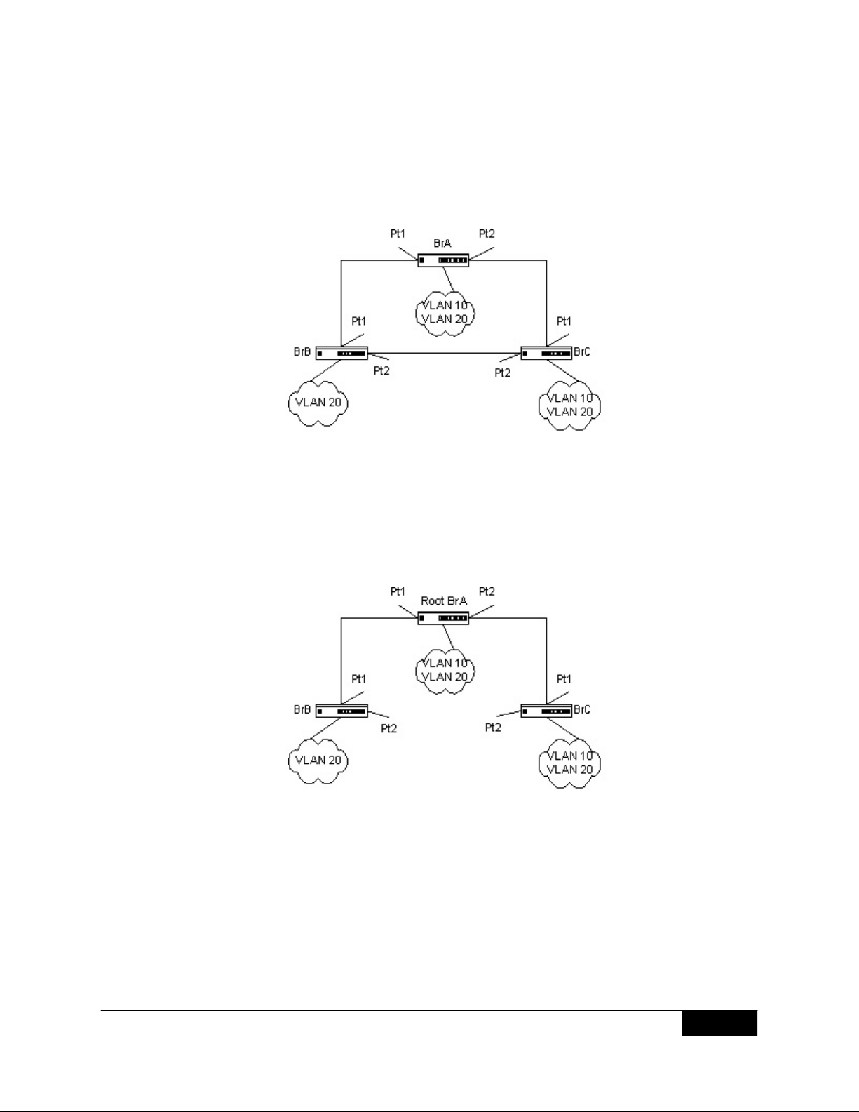
In the following diagram of a small, 802.1d bridged network, STP is necessary to create an
environment with full connectivity and without loops:
Figure 4: Small Bridged Network
Assume that bridge BrA is elected to be the Root Bridge, and Port Pt1 on bridge BrB and BrC
are calculated to be the root ports for those bridges, Port Pt2 on bridge BrB and BrC would be
placed into Blocking State. A loop-free topology would then exist. End stations in VLAN 10
could talk to other devices in VLAN 10 and end stations in VLAN 20 would only have a single
path to communicate with other VLAN 20 devices. The logical single STP network topology
would look something like this:
Figure 5: Single STP Topology
For VLAN 10, this Single STP Topology is fine and presents no limitations or inefficiencies. On
the other hand, VLAN 20’s traffic pattern is inefficient. All frames from bridge BrB will have to
traverse a path through bridge BrA before arriving at bridge BrC. If the ports Pt2 on bridge BrB
and BrC could be used, these inefficiencies could be eliminated. MSTP does just that by
allowing the configuration of MSTIs based upon a VLAN or groups of VLANs.
APRIL 2008
7
Page 8
MSTP INTEROPERABILITY OF THE DELL™ POWERCONNECT™ 6200 SERIES SWITCHES
WITH CISCO IOS AND CISCO CATOS-BASED SWITCHES
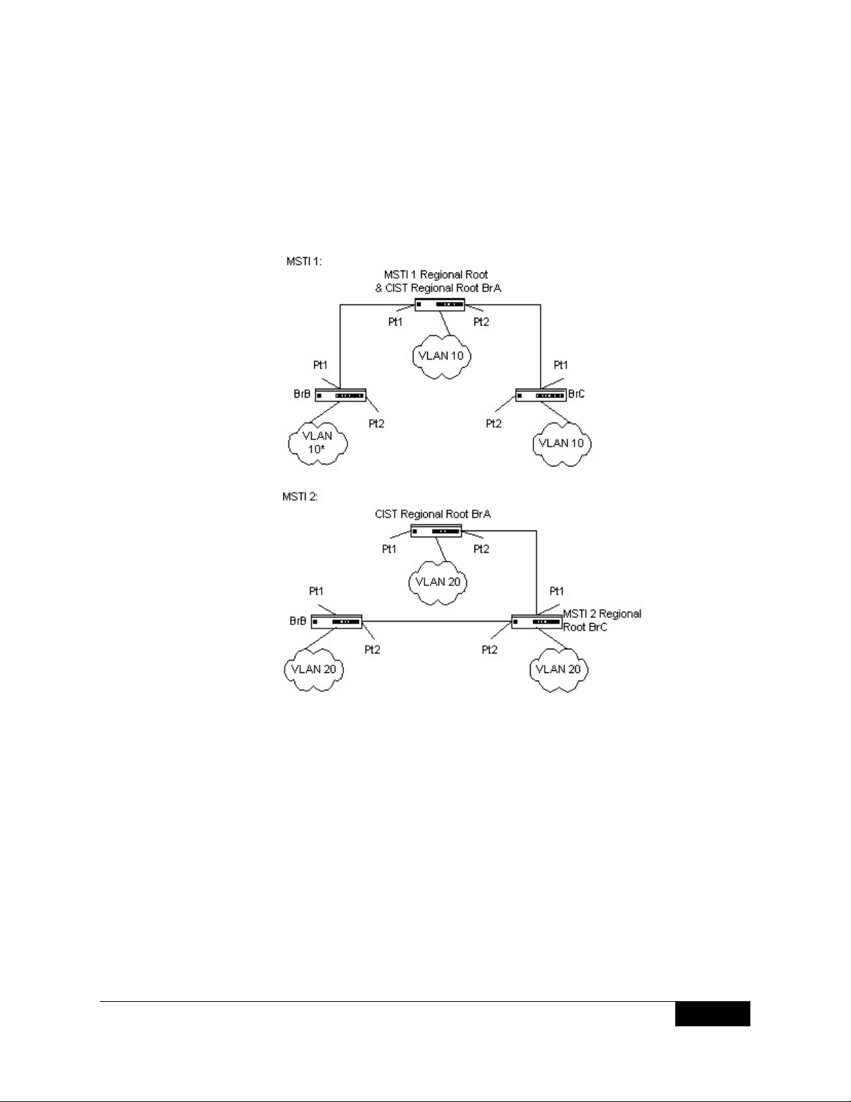
In this simple case, VLAN 10 could be associated with MSTI 1 with an active topology similar
to Figure 5, and VLAN 20 could be associated with MSTI 2 where port Pt1 on both bridge BrA
and BrB begin discarding and all others begin forwarding. This simple modification creates an
active topology with a better distribution of network traffic and an increase in available
bandwidth. The logical representation of the MSTP environment for these 3 bridges is shown in
Figure 6.
APRIL 2008
Figure 6: Logical MSTP Environment
In order for MSTP to correctly establish the different MSTIs that Figure 6 shows, some
additional changes are required. For example, the configuration would have to be the same on
each and every bridge. That means that bridge BrB would have to add VLAN 1 0 to its list of
supported VLANs (shown in Figure 6 with an “*”). This is necessary with MSTP to allow the
formation of regions made up of all bridges that exchange the same MST Configuration
Identifier. It is only within these MST regions that multiple instances can exist. It will also allow
the election of Regional Root Bridges for each instance. One CIST Regional Root for the CIST
and an MSTI Regional Root Bridge per instance will enable the possibility of alternate paths
through each Region. Above bridge BrA is elected as both the MSTI 1 Regional Root an d the
CIST Regional Root Bridge, and after adjusting the Bridge Priority on bridge Br C in MSTI 2, it
would be elected as the MSTI 2 Regional Root.
8
Page 9
MSTP INTEROPERABILITY OF THE DELL™ POWERCONNECT™ 6200 SERIES SWITCHES
WITH CISCO IOS AND CISCO CATOS-BASED SWITCHES
SAMPLE SETUP AND CONFIGURATIONS
This section contains the CLI commands you would use to configure MSTP on the switches in
Figure 6 where two bridges are Dell PowerConnect switches, and the third bridge is a Cisco
Catalyst switch.
The three switches in the figure are as follows:
• BrA: Dell PowerConnect 6248
• BrB: Dell PowerConnect 6248
• BrC: CiscoCatalyst3750series
BrA is the root bridge for MSTP instance 1, and BrC is the root bridge for MSTP instance 2.
CONFIGURING BRIDGE BrA (CLI)
Use the commands in this section to configure the Dell PowerConnect 6248 as bridge BrA as
shown in Figure 6.
Dell_BrA(config)#vlan database
Dell_BrA(config-vlan)#vlan 10,20
Dell_BrA(config-vlan)#exit
Dell_BrA(config)#interface ethernet 1/g1
Dell_BrA(config-if-1/g1)#switchport mode trunk
Dell_BrA(config-if-1/g1)#switchport trunk allowed vlan add 10,20
Dell_BrA(config-if-1/g1)#switchport trunk allowed vlan remove 1
Dell_BrA(config-if-1/g1)#exit
Dell_BrA(config)#interface ethernet 1/g2
Dell_BrA(config-if-1/g1)#switchport mode trunk
Dell_BrA(config-if-1/g1)#switchport trunk allowed vlan add 10,20
Dell_BrA(config-if-1/g1)#switchport trunk allowed vlan remove 1
Dell_BrA(config-if-1/g1)#exit
Dell_BrA(config)#spanning-tree mode mstp
Dell_BrA(config)#spanning-tree mst 1 priority 0
Dell_BrA(config)#spanning-tree mst configuration
Dell_BrA(config-mst)#name Dell
Dell_BrA(config-mst)#instance 1 add vlan 10
Dell_BrA(config-mst)#instance 2 add vlan 20
Dell_BrA(config-mst)#exit
APRIL 2008
Command Description
vlan database
vlan 10, 20
exit
interface Ethernet 1/g1
switchport mode trunk
switchport trunk allowed
vlan add 10, 20
switchport trunk allowed
vlan remove 1
Enter VLAN command mode
Create VLANs 10 and 20
Exit to configuration mode
Enter interface configuration mode for the
Ethernet interface on slot 1, port 1
Configure the VLAN membership mode
for the port as a trunk (a trunk port
connects two switches)
Add VLANs 10 and 20 to the trunk port
Remove VLAN 1 (the default VLAN) from
the trunk port
9
Page 10

MSTP INTEROPERABILITY OF THE DELL™ POWERCONNECT™ 6200 SERIES SWITCHES
WITH CISCO IOS AND CISCO CATOS-BASED SWITCHES
Command Description
exit
interface ethernet 1/g2
switchport mode trunk
switchport trunk allowed
vlan add 10, 20
Exit to configuration mode
Enter interface configuration mode for the
Ethernet interface on slot 1, port 2
Configure the VLAN membership mode for
the port as a trunk (a trunk port connects
two switches)
Add VLANs 10 and 20 to the trunk port
switchport trunk allowed
vlan remove 1
exit
spanning-tree mode mstp
spanning-tree mst 1 priority 0
spanning-tree mst configuration
name Dell
instance 1 add vlan 10
instance 2 add vlan 20
exit
CONFIGURING BRIDGE BrA (WEB INTERFACE)
Use the following procedures to configure the Dell PowerConnect 6248 as bridge BrA as
shown in Figure 6 by using the Web interface.
Remove VLAN 1 (the default VLAN) from
the trunk port
Exit to configuration mode
Enable MSTP mode on the switch
Sets the switch priority for MSTP instance
1 to zero, which essentially sets the switch
as the root bridge for MSTP instance 1.
Enter the MST configuration name
Create Dell as the MST configuration name
Map VLAN 10 to MST instance 1
Map VLAN 20 to MST instance 2
Exit to configuration mode
APRIL 2008
10
Page 11

MSTP INTEROPERABILITY OF THE DELL™ POWERCONNECT™ 6200 SERIES SWITCHES
WITH CISCO IOS AND CISCO CATOS-BASED SWITCHES
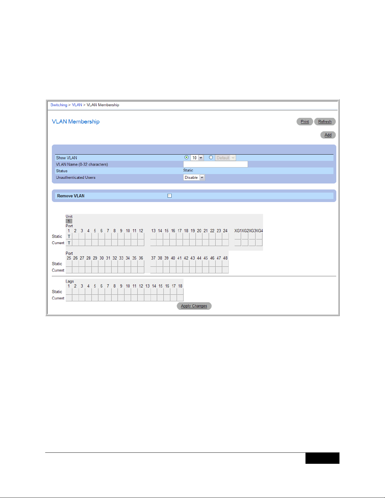
1. From the Switching > VLAN > VLAN Membership page, click Add.
APRIL 2008
2. From the Add VLAN page, enter 10 in the VLAN ID field and click Apply Changes.
11
Page 12

MSTP INTEROPERABILITY OF THE DELL™ POWERCONNECT™ 6200 SERIES SWITCHES
WITH CISCO IOS AND CISCO CATOS-BASED SWITCHES
3. Add VLAN 20.
4. To configure Port g1 as a trunk port, go to the Switching > VLAN > Port Settings page,
select Trunk from the Port VLAN Mode menu for Port g1, and click Apply Changes.
APRIL 2008
12
Page 13
MSTP INTEROPERABILITY OF THE DELL™ POWERCONNECT™ 6200 SERIES SWITCHES
WITH CISCO IOS AND CISCO CATOS-BASED SWITCHES
5. On the Sw itching > VLAN > VLAN Membership page, select VLAN 10 from the Show
VLAN menu.
6. Add port 1 to VLAN 10 as a tagged interface.
APRIL 2008
13
Page 14
MSTP INTEROPERABILITY OF THE DELL™ POWERCONNECT™ 6200 SERIES SWITCHES
WITH CISCO IOS AND CISCO CATOS-BASED SWITCHES
7. Select VLAN 20 from the Show VLAN menu and add port 1 as a tagged interface.
8. Repeat steps 4-7 to configure Port 2 as a Trunk port with VLAN members 10 and 20.
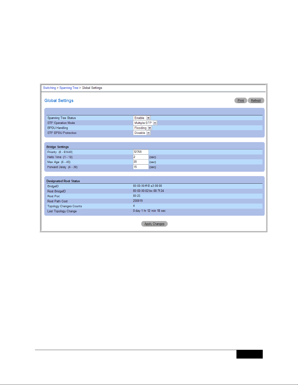
9. From the Switching > Spanning Tree > Global Settings page, enable MSTP and select
Multiple STP from the STP Operation Mode menu.
APRIL 2008
10. Click Apply Changes.
14
Page 15

MSTP INTEROPERABILITY OF THE DELL™ POWERCONNECT™ 6200 SERIES SWITCHES
WITH CISCO IOS AND CISCO CATOS-BASED SWITCHES
11. On the Switching > Spanning Tree > MSTP Settings page, enter Dell as the
Region Name, 0 as the Priority, and click Apply Changes.
APRIL 2008
12. Click Show All to access the MSTP Settings Table.
13. Click the Edit option for VLANs 10 and 20.
14. To map the VLANs to the appropriate MSTP instances, enter 1 in the Instance ID field
for VLAN 10 and 2 in the Instance ID field for VLAN 20, and then click Apply Changes.
15
Page 16

MSTP INTEROPERABILITY OF THE DELL™ POWERCONNECT™ 6200 SERIES SWITCHES
WITH CISCO IOS AND CISCO CATOS-BASED SWITCHES
CONFIGURING BRIDGE BrB
To configure Bridge BrB, use the same commands as you used to configure Bridge BrA with
one exception: do not use the spanning-tree mst 1 priority 0 command on Bridge
BrB because it is not a root bridge for any instance. If you use the Web interface to configure
Bridge BrB, do not enter a new value in the Priority field on the Switching > Spanning Tree >
MSTP Settings page.
CONFIGURING BRIDGE BrC
Use the commands in this section to configure the Cisco Catalyst3750 switch as bridge BrA.
Cisco3750_BrC(vlan)#vlan 10
VLAN 10 added:
Name: VLAN010
Cisco3750_BrC(vlan)#vlan 20
VLAN 20 added:
Name: VLAN020
Cisco3750_BrC(vlan)#exit
APPLY completed.
Exiting....
Cisco3750_BrC#configure terminal
Cisco3750_BrC(config)#interface GigabitEthernet 1/0/1
Cisco3750_BrC(config-if)#switchport trunk encapsulation dot1q
Cisco3750_BrC(config-if)#switchport trunk allowed vlan 10,20
Cisco3750_BrC(config-if)#switchport mode trunk
Cisco3750_BrC(config-if)#exit
Cisco3750_BrC(config)#interface GigabitEthernet 1/0/2
Cisco3750_BrC(config-if)#switchport trunk encapsulation dot1q
Cisco3750_BrC(config-if)#switchport trunk allowed vlan 10,20
Cisco3750_BrC(config-if)#switchport mode trunk
Cisco3750_BrC(config-if)#exit
Cisco3750_BrC(config)#spanning-tree mst configuration
Cisco3750_BrC(config-mst)#name Dell
Cisco3750_BrC(config-mst)#instance 1 vlan 10
Cisco3750_BrC(config-mst)#instance 2 vlan 20
Cisco3750_BrC(config-mst)#exit
Cisco3750_BrC(config)#spanning-tree mst 2 priority 0
Cisco3750_BrC(config)#exit
Cisco3750_BrC#exit
APRIL 2008
Command Description
vlan 10
vlan 20
exit
configure terminal
interface GigabitEthernet 1/0/1
switchport trunk
encapsulation dot1q
switchport trunk allowed
vlan 10,20
Create VLAN 10
Create VLAN 20
Exit to privileged EXEC mode
Enter configuration mode
Enter configuration mode for the
interface on slot 1, port 1
Set the trunking encapsulation format
to 802.1Q
Add VLANs 10 and 20 to the trunk port
16
Page 17

MSTP INTEROPERABILITY OF THE DELL™ POWERCONNECT™ 6200 SERIES SWITCHES
WITH CISCO IOS AND CISCO CATOS-BASED SWITCHES
Command Description
switchport mode trunk
Enable trunking on the interface
exit
interface GigabitEthernet 1/0/2
switchport trunk
encapsulation dot1q
switchport trunk allowed
vlan 10,20
switchport mode trunk
exit
spanning-tree mst configuration
name Dell
instance 1 vlan 10
instance 2 vlan 20
exit
spanning-tree mst 2 priority 0
exit
Exit to configuration mode
Enter configuration mode for the interface
on slot 1, port 2
Set the trunking encapsulation format
to 802.1Q
Add VLANs 10 and 20 to the trunk port
Enable trunking on the interface
Exit to configuration mode
Enter the configuration mode for MST
Create Dell as the MST configuration name
Map VLAN 10 to MST instance 1
Map VLAN 20 to MST instance 2
Exit to configuration mode
Sets the switch priority for MSTP instance
2 to zero, which essentially sets this switch
as the root bridge for MSTP instance 2
Exit to Privileged EXEC mode
APRIL 2008
CONFIGURING EDGE DEVICES
The configuration examples for BrA, BrB, and BrC show trunk ports between bridges. To
configure a port to any VLAN-unaware devices or edge devices, you must add the ports in
access mode. An access port connects to a single end station belonging to a single VLAN.
The following commands, executed on the Dell PowerConnect switch BrB, show how to send
untagged traffic into port 1/g5 that must pass through vlan 10 or MSTP instance 1.
Dell_BrB(config)#interface ethernet 1/g5
Dell_BrB(config-if-1/g5)#switchport mode access
Dell_BrB(config-if-1/g5)#switchport access vlan 10
Dell_BrB(config-if-1/g5)#exit
Command Description
interface ethernet 1/g5
switchport mode access
switchport access vlan 10
exit
Enter configuration mode for the interface
on slot 1, port 5
Configure the VLAN membership mode of
the port as access
Configure the VLAN ID to use when the
interface is in access mode. This also sets
port PVID to 10
Exit to configuration mode
17
Page 18

MSTP INTEROPERABILITY OF THE DELL™ POWERCONNECT™ 6200 SERIES SWITCHES
WITH CISCO IOS AND CISCO CATOS-BASED SWITCHES
To perform the same configuration by using the Web interface, go to the Switching > VLAN >
VLAN Membership page, and add port 5 as an access ports in VLAN 10. Ethernet traffic on
this port will be untagged.
APRIL 2008
VIEWING THE MSTP STATUS
You can view the MSTP Region configuration on the three bridge s by using the follow ing command:
show spanning-tree mst configuration
The command is the same on the Dell and Cisco switches.
18
Page 19

MSTP INTEROPERABILITY OF THE DELL™ POWERCONNECT™ 6200 SERIES SWITCHES
WITH CISCO IOS AND CISCO CATOS-BASED SWITCHES
Bridge BrA (Dell)
Dell_BrA#show spanning-tree mst-configuration
Name: Dell
Revision: 0
Instance Vlan Mapped
-------- -----------
0 1
1 10
2 20
Bridge BrB (Dell)
Dell_BrB#show spanning-tree mst-configuration
Name: Dell
Revision: 0
Instance Vlan Mapped
-------- -----------
0 1
1 10
2 20
Bridge BrC (Cisco)
Cisco3750_BrC#show spanning-tree mst configuration
Name [Dell]
Revision 0 Instances configured 3
Instance Vlan Mapped
-------- -----------
0 1-9,11-19,21-4094
1 10
2 20
ADDITIONAL MSTP STATUS INFORMATION
You can also view information about MSTP states with the following command:
show spanning-tree active
The command is the same on the Dell and Cisco switches.
APRIL 2008
19
Page 20

MSTP INTEROPERABILITY OF THE DELL™ POWERCONNECT™ 6200 SERIES SWITCHES
WITH CISCO IOS AND CISCO CATOS-BASED SWITCHES
Bridge BrC (Cisco)
Cisco3750_BrC#show spanning-tree active
MST0
Spanning tree enabled protocol mstp
Root ID Priority 32768
Address 0000.0000.0fff
Cost 0
Port 1 (GigabitEthernet1/0/1)
Hello Time 2 sec
Max Age 20 sec
Forward Delay 15 sec
Bridge ID Priority 32768
(priority 32768 sys-id-ext 0)
Address 0015.6210.2900
Hello Time 2 sec
Max Age 20 sec
Forward Delay 15 sec
Interface Role Sts Cost Prio.Nbr Type
---------- ---- --- ----- -------- -----
Gi1/0/1 Root FWD 20000 128.1 P2p
Gi1/0/2 Desg FWD 20000 128.2 P2p
MST1
Spanning tree enabled protocol mstp
Root ID Priority 32769
Address 0000.0000.0fff
Cost 20000
Port 1 (GigabitEthernet1/0/1)
Hello Time 2 sec
Max Age 20 sec
Forward Delay 15 sec
Bridge ID Priority 32769
(priority 32768 sys-id-ext 1)
Address 0015.6210.2900
Hello Time 2 sec
Max Age 20 sec
Forward Delay 15 sec
Interface Role Sts Cost Prio.Nbr Type
---------- ---- --- ----- -------- -----
Gi1/0/1 Root FWD 20000 128.1 P2p
Gi1/0/2 Desg FWD 20000 128.2 P2p
MST2
Spanning tree enabled protocol mstp
Root ID Priority 2
Address 0015.6210.2900
This bridge is the root
Hello Time 2 sec
Max Age 20 sec
Forward Delay 15 sec
Bridge ID Priority 2
(priority 0 sys-id-ext 2)
Address 0015.6210.2900
Hello Time 2 sec
Max Age 20 sec
Forward Delay 15 sec
APRIL 2008
20
Page 21

MSTP INTEROPERABILITY OF THE DELL™ POWERCONNECT™ 6200 SERIES SWITCHES
WITH CISCO IOS AND CISCO CATOS-BASED SWITCHES
Interface Role Sts Cost Prio.Nbr Type
---------- ---- --- ----- -------- -----
Gi1/0/1 Desg FWD 20000 128.1 P2p
Gi1/0/2 Desg FWD 20000 128.2 P2p
Cisco3750_BrC#
Bridge BrA (Dell)
Dell_BrA# show spanning-tree active
Spanning tree Enabled mode mstp
CST Regional Root: 80:00:00:00:00:00:0F:FF
Regional Root Path Cost: 0
###### MST 0 Vlan Mapped: 1
ROOT ID
Address 80:00:00:00:00:00:0F:FF
This Switch is the Root.
Hello Time 2 Sec
Max Age 20 sec
Forward Delay 15 sec
Interfaces
Name State Prio.Nbr Cost Sts Role PortFast RootPort
------ ----- -------- ----- ---- ----- -------- -------
1/g1 Enabled 128.1 20000 FWD Desg No No
1/g2 Enabled 128.2 20000 FWD Desg No No
###### MST 1 Vlan Mapped: 10
ROOT ID
Address 80:01:00:00:00:00:0F:FF
This Switch is the Root.
Hello Time 2 Sec
Max Age 20 sec
Forward Delay 15 sec
Interfaces
Name State Prio.Nbr Cost Sts Role PortFast RootPort
------ ----- -------- ----- ---- ----- -------- -------
1/g1 Enabled 128.1 20000 FWD Desg No No
1/g2 Enabled 128.2 20000 FWD Desg No No
###### MST 2 Vlan Mapped: 20
ROOT ID
Address 00:02:00:15:62:10:29:00
Path Cost 20000
Root Port 1/g1
Hello Time 2 Sec
Max Age 20 sec
Forward Delay 15 sec
Bridge ID
Priority 32768
Address 80:02:00:00:00:00:0F:FF
Hello Time 2 Sec
Max Age 20 sec
Forward Delay 15 sec
Interfaces
Name State Prio.Nbr Cost Sts Role PortFast RootPort
------ -------- --------- ---------- ---- ----- -------- -------
1/g1 Enabled 128.1 20000 FWD Root No No
1/g2 Enabled 128.2 20000 FWD Desg No No
Dell_BrA#
APRIL 2008
21
Page 22

MSTP INTEROPERABILITY OF THE DELL™ POWERCONNECT™ 6200 SERIES SWITCHES
WITH CISCO IOS AND CISCO CATOS-BASED SWITCHES
Bridge BrB (Dell)
Dell_BrB#show spanning-tree active
Spanning tree Enabled mode mstp
CST Regional Root: 80:00:00:00:00:00:0F:FF
Regional Root Path Cost: 20000
###### MST 0 Vlan Mapped: 1
ROOT ID
Address 80:00:00:00:00:00:0F:FF
Path Cost 0
Root Port 1/g1
Hello Time 2 Sec
Max Age 20 sec
Forward Delay 15 sec
Bridge ID
Priority 32768
Address 80:00:00:84:00:00:0F:FF
Hello Time 2 Sec
Max Age 20 sec
Forward Delay 15 sec
Interfaces
Name State Prio.Nbr Cost Sts Role PortFast RootPort
------ ----- -------- ----- ---- ----- -------- -------
1/g1 Enabled 128.1 20000 FWD Root No No
1/g2 Enabled 128.2 20000 DSC Altn No No
###### MST 1 Vlan Mapped: 10
ROOT ID
Address 80:01:00:00:00:00:0F:FF
Path Cost 20000
Root Port 1/g1
Hello Time 2 Sec
Max Age 20 sec
Forward Delay 15 sec
Bridge ID
Priority 32768
Address 80:01:00:84:00:00:0F:FF
Hello Time 2 Sec
Max Age 20 sec
Forward Delay 15 sec
Interfaces
Name State Prio.Nbr Cost Sts Role PortFast RootPort
------ ----- -------- ----- ---- ----- -------- -------
1/g1 Enabled 128.1 20000 FWD Root No No
1/g2 Enabled 128.2 20000 DSC Altn No No
APRIL 2008
22
Page 23

MSTP INTEROPERABILITY OF THE DELL™ POWERCONNECT™ 6200 SERIES SWITCHES
WITH CISCO IOS AND CISCO CATOS-BASED SWITCHES
###### MST 2 Vlan Mapped: 20
ROOT ID
Address 00:02:00:15:62:10:29:00
Path Cost 20000
Root Port 1/g2
Hello Time 2 Sec
Max Age 20 sec
Forward Delay 15 sec
Bridge ID
Priority 32768
Address 80:02:00:84:00:00:0F:FF
Hello Time 2 Sec
Max Age 20 sec
Forward Delay 15 sec
Interfaces
Name State Prio.Nbr Cost Sts Role PortFast RootPort
------ ----- -------- ----- ---- ----- -------- -------
1/g1 Enabled 128.1 20000 DSC Altn No No
1/g2 Enabled 128.2 20000 FWD Root No No
Dell_BrB#
ADDITIONAL INFORMATION AND SCALABILITY WITH MORE REGIONS
To further illustrate the full connectivity in an MSTP active topology, the following rules apply:
• Each Bridge or LAN is in one and only one MSTP region.
• Every frame is associated with one and only one VID.
• Frames are allocated either to the IST or MSTI within any given region.
• The IST and each MSTI provides full and simple connectivity between all LANs and
bridges in a region.
• All bridges within a region reach a consistent agreement as to which ports interconnect
that region to a different region and label those as boundary ports.
• At the boundary ports, frames allocated to the CIST or MSTIs are forwarded or not
forwarded alike.
• The CIST provides full and simple connectivity betw een all LANs and b ridges in the network.
Frames with VIDs not allocated to an + MSTI will be implicitly assigned to the CIST (or IST within
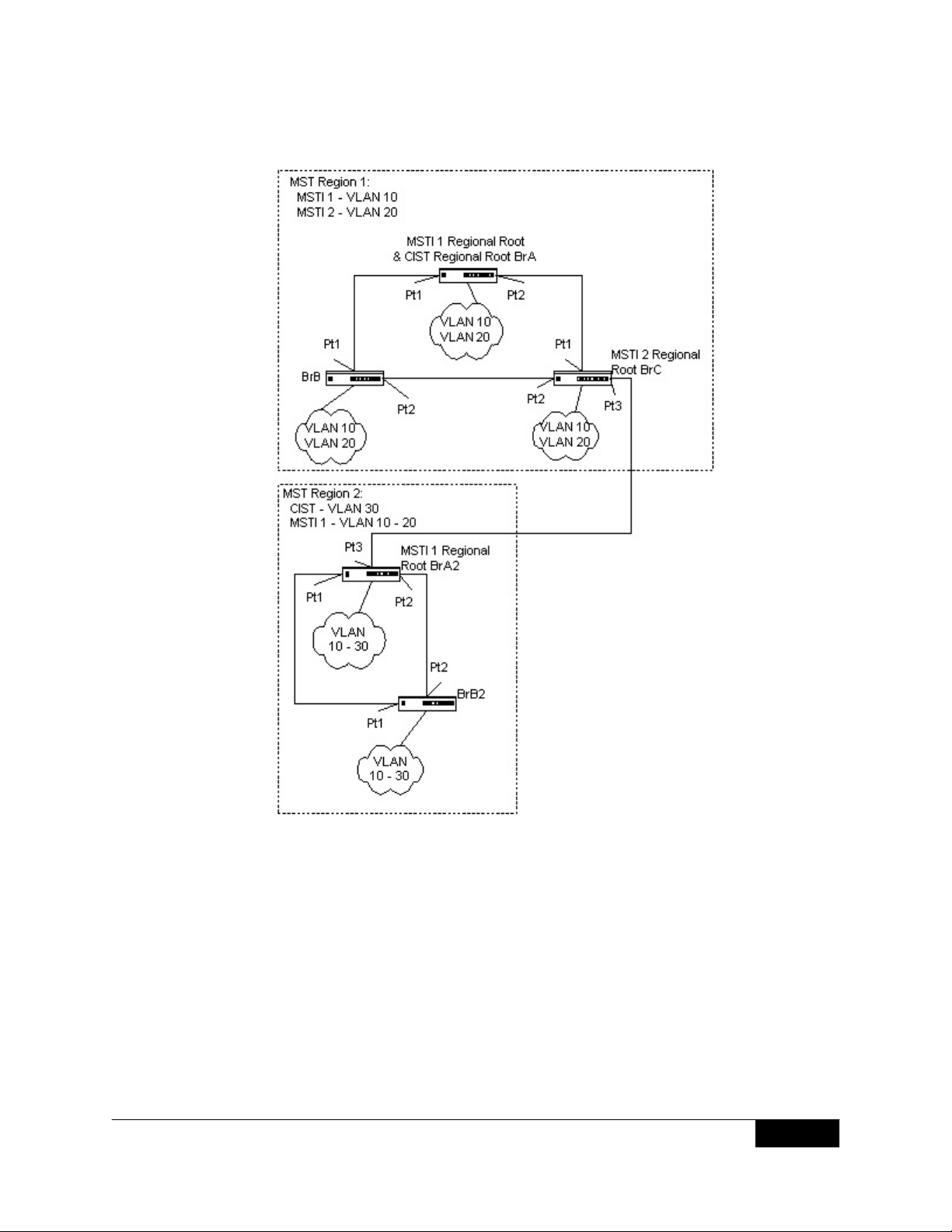
the region), and they will be processed or passed on through the region. For example, in
Figure 7, VLAN 30 is not explicitly assigned to any instance but by default, it will still rely on the
CIST since the two bridges define a region (MST Region 2). Since the two bridges process
frames internal to Region 2, an MSTI Regional Root Bridge must again be elected. In this
example, Bridge BrA2 is chosen since it has the lowest external root path cost through a
boundary port.
APRIL 2008
23
Page 24
MSTP INTEROPERABILITY OF THE DELL™ POWERCONNECT™ 6200 SERIES SWITCHES
WITH CISCO IOS AND CISCO CATOS-BASED SWITCHES
APRIL 2008
Figure 7: Multiple MSTP Regions
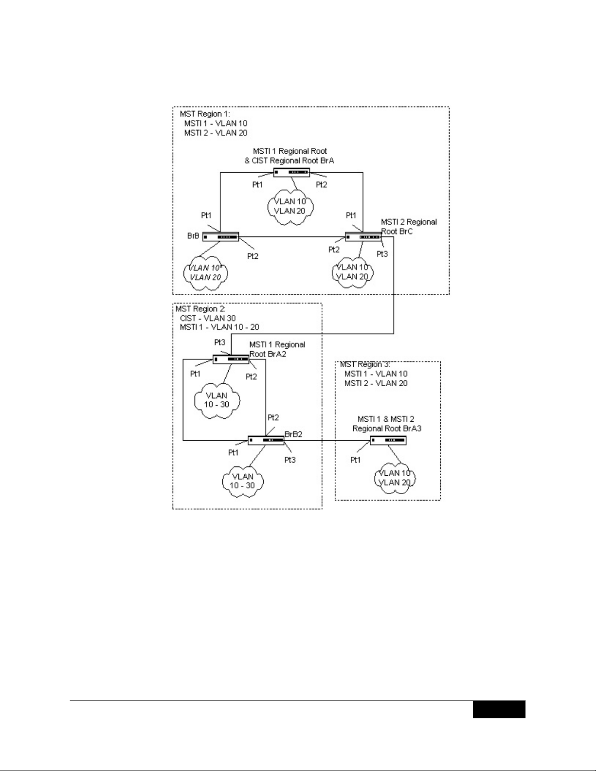
In Figure 8, a third region has been added to the topology. Even though this new region only
consists of one bridge and has an MST Configuration Identifier that matches the bridges in
Region 1, it will still be isolated into a region by itself. This is due to the fact that the only
connection between Region 1 and Region 3 is through a different region.
The path of a frame for VLAN 20 can be traced through the MST active topology. A frame
originating on an end station on bridge BrA in Region 1 will traverse the MSTI 2 active topology
since its VID has been allocated to that instance. In looking for a destination match with a
device in Region 3, it will pass through the boundary port in bridge BrC and continue through
Region 2 using the instance MSTI 1. Assuming that port Pt2 on both bridge BrA2 and BrB2 are
forwarding for the MSTI 1, the frame would arrive at the boundary port on bridge BrB2 and
then be sent to Region 3. Upon arriving in Region 3, the frame would traverse MSTI 2 to the
destination device.
24
Page 25
MSTP INTEROPERABILITY OF THE DELL™ POWERCONNECT™ 6200 SERIES SWITCHES
WITH CISCO IOS AND CISCO CATOS-BASED SWITCHES
APRIL 2008
Figure 8: Multiple MSTP Region Interactions
25
 Loading...