

Page 1

Dell™ PowerConnect™ 6024/6024F Systems
User’s Guide
www.dell.com | support.dell.com
Page 2

Notes, Notices, and Cautions
NOTE: A NOTE indicates important information that helps you make better use of your computer.
NOTICE: A NOTICE indicates either potential damage to hardware or loss of data and tells you how to
avoid the problem.
CAUTION: A CAUTION indicates a potential for property damage, personal injury, or death.
____________________
Information in this document is subject to change without notice.
© 2005 Dell Inc. All rights reserved.
Reproduction in any manner whatsoever without the written permission of Dell Inc. is strictly forbidden.
Trademarks used in this text: Dell, Dell OpenManage, the DELL logo, Inspiron, Dell Precision, Dimension, OptiPlex,
PowerConnect, PowerApp, PowerVault, Axim, DellNet, and Latitude are trademarks of Dell Inc. Microsoft and Windows are
registered trademarks of Microsoft Corporation.
Other trademarks and trade names may be used in this document to refer to either the entities claiming the marks and names or
their products. Dell Inc. disclaims any proprietary interest in trademarks and trade names other than its own.
April 2005 Rev A04
Page 3

Contents
1 Introduction
PowerConnect 6024 . . . . . . . . . . . . . . . . . . . . . . . . . . . . 23
PowerConnect 6024F
CLI Documentation
Features
. . . . . . . . . . . . . . . . . . . . . . . . . . . . . . . . . . 24
Port Based Features
MAC Address Supported Features
Layer 2 Features
VLAN Supported Features
Spanning Tree Protocol Features
Link Aggregation
Routing Features
Layer 3 Features
Quality of Service Features
Device Management Features
Security Features
. . . . . . . . . . . . . . . . . . . . . . . . . . . . 24
. . . . . . . . . . . . . . . . . . . . . . . . . . . . . 24
. . . . . . . . . . . . . . . . . . . . . . . . . . 24
. . . . . . . . . . . . . . . . . . . 26
. . . . . . . . . . . . . . . . . . . . . . . . . . . 26
. . . . . . . . . . . . . . . . . . . . . . . 27
. . . . . . . . . . . . . . . . . . . . 28
. . . . . . . . . . . . . . . . . . . . . . . . . . . 29
. . . . . . . . . . . . . . . . . . . . . . . . . . . 29
. . . . . . . . . . . . . . . . . . . . . . . . . . . 31
. . . . . . . . . . . . . . . . . . . . . . 31
. . . . . . . . . . . . . . . . . . . . . 32
. . . . . . . . . . . . . . . . . . . . . . . . . . . 34
2 Hardware Description
Ports Description . . . . . . . . . . . . . . . . . . . . . . . . . . . . . 37
PowerConnect 6024
PowerConnect 6024F
Out-of-Band Management Port
Console (RS-232) Port
. . . . . . . . . . . . . . . . . . . . . . . . . . 37
. . . . . . . . . . . . . . . . . . . . . . . . . 38
. . . . . . . . . . . . . . . . . . . . 38
. . . . . . . . . . . . . . . . . . . . . . . . . 38
Hardware Components
Physical Dimensions
Power Supplies
Reset Button
. . . . . . . . . . . . . . . . . . . . . . . . . . . . . 40
Ventilation System
LED Definitions
SFP Port LEDs
System LEDs
. . . . . . . . . . . . . . . . . . . . . . . . . . . . . . 40
. . . . . . . . . . . . . . . . . . . . . . . . . . . . . 41
. . . . . . . . . . . . . . . . . . . . . . . . . . . . . 42
. . . . . . . . . . . . . . . . . . . . . . . . . . . 39
. . . . . . . . . . . . . . . . . . . . . . . . . 39
. . . . . . . . . . . . . . . . . . . . . . . . . . . . 39
. . . . . . . . . . . . . . . . . . . . . . . . . . . 40
Contents 3
Page 4

3 Cable, Port, and Pinout Information
Pin Connections for the 10/100/1000 Ethernet Interface . . . . . . . . . . . 45
Pin Connections for SFP Interfaces
Serial Cable Connection
. . . . . . . . . . . . . . . . . . . . . . . . . . 47
Connecting the Switch to a Terminal
AC Power Connection
. . . . . . . . . . . . . . . . . . . . . . . . . . . 49
. . . . . . . . . . . . . . . . . . . . . 46
. . . . . . . . . . . . . . . . . . 48
4 Using Dell OpenManage Switch Administrator
Starting the Application . . . . . . . . . . . . . . . . . . . . . . . . . . 51
Understanding the Interface
Using the Switch Administrator Buttons
Information Buttons
Device Management Buttons
Defining Fields
. . . . . . . . . . . . . . . . . . . . . . . . . . . . . . 54
Accessing the Switch Through the CLI
Console Connection
Telnet Connection
Using the CLI
. . . . . . . . . . . . . . . . . . . . . . . . . . . . . . . 56
Command Mode Overview
User EXEC Mode
Privileged EXEC Mode
Global Configuration Mode
Interface Configuration Mode
CLI Examples
. . . . . . . . . . . . . . . . . . . . . . . . . . . . . 58
. . . . . . . . . . . . . . . . . . . . . . . . 51
. . . . . . . . . . . . . . . . . . 53
. . . . . . . . . . . . . . . . . . . . . . . . . . 53
. . . . . . . . . . . . . . . . . . . . . 54
. . . . . . . . . . . . . . . . . . . 55
. . . . . . . . . . . . . . . . . . . . . . . . . . 55
. . . . . . . . . . . . . . . . . . . . . . . . . . . 55
. . . . . . . . . . . . . . . . . . . . . . . 56
. . . . . . . . . . . . . . . . . . . . . . . . . . . 56
. . . . . . . . . . . . . . . . . . . . . . . . . 56
. . . . . . . . . . . . . . . . . . . . . . 57
. . . . . . . . . . . . . . . . . . . . . 58
5 Configuring the Switch
4 Contents
General Configuration Information . . . . . . . . . . . . . . . . . . . . . 61
Auto-Negotiation
Switching Port Default Settings
Terminal Connection Configuration
Baud Rate
Other Configuration Requirements
. . . . . . . . . . . . . . . . . . . . . . . . . . . 61
. . . . . . . . . . . . . . . . . . . . 61
. . . . . . . . . . . . . . . . . . . 62
. . . . . . . . . . . . . . . . . . . . . . . . . . . . . . 62
. . . . . . . . . . . . . . . . . . . . . 63
Page 5

Booting the Switch . . . . . . . . . . . . . . . . . . . . . . . . . . . . 63
Configuration Overview
Initial Configuration
Advanced Configuration
. . . . . . . . . . . . . . . . . . . . . . . . . . 66
. . . . . . . . . . . . . . . . . . . . . . . . . . . . 66
. . . . . . . . . . . . . . . . . . . . . . . . . . 70
Retrieving an IP Address From a DHCP Server
Receiving an IP Address From a BOOTP Server
Security Management and Password Configuration
Configuring Security Passwords
Software Download and Reboot
. . . . . . . . . . . . . . . . . . . . 72
. . . . . . . . . . . . . . . . . . . . . . 74
Software Download Through XModem
Software Download Through TFTP Server
Boot Image Download
Sample Configuration Process
Device Setup Requirements
Initial Connection
Device Default Settings
Enabling Remote Management
. . . . . . . . . . . . . . . . . . . . . . . . . 77
. . . . . . . . . . . . . . . . . . . . . . . 77
. . . . . . . . . . . . . . . . . . . . . . 78
. . . . . . . . . . . . . . . . . . . . . . . . . . . 78
. . . . . . . . . . . . . . . . . . . 82
. . . . . . . . . . . . . . . . . . . . . 82
Setting the Management Station IP Address
Enabling Telnet Access
Enabling Web Access (HTTP Server)
. . . . . . . . . . . . . . . . . . . . . . . . 87
. . . . . . . . . . . . . . . . . . 89
Configuring Secure Management Access (HTTPS)
. . . . . . . . . . . . . 70
. . . . . . . . . . . . . 71
. . . . . . . . . . . 72
. . . . . . . . . . . . . . . . . 74
. . . . . . . . . . . . . . . 75
. . . . . . . . . . . . . . 85
. . . . . . . . . . . 91
Startup Menu Functions
Download Software
Erase FLASH File
Erase FLASH Sectors
Password Recovery
Out-of-Band Management Port
. . . . . . . . . . . . . . . . . . . . . . . . . . 92
. . . . . . . . . . . . . . . . . . . . . . . . . . 93
. . . . . . . . . . . . . . . . . . . . . . . . . . . 93
. . . . . . . . . . . . . . . . . . . . . . . . . 94
. . . . . . . . . . . . . . . . . . . . . . . . . . 95
. . . . . . . . . . . . . . . . . . . . . . . 95
Assigning Dynamic IP Addresses (on an Out-of-Band Port)
Assigning Static IP Addresses (on an Out-of-Band Port)
Assigning IP Default Gateway
Ping via Out-of-Band
Copy Image/Boot
. . . . . . . . . . . . . . . . . . . . . . . . . 96
. . . . . . . . . . . . . . . . . . . . . . . . . . . 96
IP Default Gateway to Out-of-Band
Additional Information
. . . . . . . . . . . . . . . . . . . . . 96
. . . . . . . . . . . . . . . . . . . 96
. . . . . . . . . . . . . . . . . . . . . . . . . 97
. . . . . . . 95
. . . . . . . . . 96
Contents 5
Page 6

6 Configuring System Information
Opening the System Page . . . . . . . . . . . . . . . . . . . . . . . . . 99
Defining General Device Information
Configuring Device Information
Defining System Time Settings
. . . . . . . . . . . . . . . . . . . . 99
. . . . . . . . . . . . . . . . . . . . 99
. . . . . . . . . . . . . . . . . . . . 102
The following is an example of CLI commands:
Configuring System Health Information
. . . . . . . . . . . . . . . . 105
The following is an example of the CLI commands:
Version Information
Resetting the Device
Configuring SNTP Settings
Defining SNTP Global Parameters
Defining SNTP Authentication Methods
Defining SNTP Servers
Defining SNTP Interfaces
. . . . . . . . . . . . . . . . . . . . . . . . . 108
. . . . . . . . . . . . . . . . . . . . . . . . 109
. . . . . . . . . . . . . . . . . . . . . . . . 110
. . . . . . . . . . . . . . . . . . 111
. . . . . . . . . . . . . . . 114
. . . . . . . . . . . . . . . . . . . . . . . 116
. . . . . . . . . . . . . . . . . . . . . . 120
Configuring Out-of-Band (OOB) Management Ports
Configuring Out-of-Band Remote Log Servers
Defining Out-of-Band Default Gateways
. . . . . . . . . . . . . . . 124
Defining Out-of-Band IP Interface Parameters
Configuring Out-of-Band TACACS+ Servers
Configuring Out-of-Band RADIUS Servers
Managing Logs
Global Log Parameters
RAM Log Table
Log File Table
Remote Log Server
. . . . . . . . . . . . . . . . . . . . . . . . . . . . . 135
. . . . . . . . . . . . . . . . . . . . . . . 135
. . . . . . . . . . . . . . . . . . . . . . . . . . . 138
. . . . . . . . . . . . . . . . . . . . . . . . . . . . 139
. . . . . . . . . . . . . . . . . . . . . . . . . 141
. . . . . . . . . . . . . . 127
. . . . . . . . . . . . . . 132
. . . . . . . . . . . . 105
. . . . . . . . . . 107
. . . . . . . . . . . . 122
. . . . . . . . . . . . 122
. . . . . . . . . . . . 125
6 Contents
Defining IP Addressing
Defining IP Interfaces
. . . . . . . . . . . . . . . . . . . . . . . . . . 143
. . . . . . . . . . . . . . . . . . . . . . . . 144
Defining DHCP IP Interface Parameters
Configuring Domain Name Systems
Defining Default Domains
Mapping the Domain Host
Enabling ARP Proxy
Defining ARP Settings
. . . . . . . . . . . . . . . . . . . . . . 151
. . . . . . . . . . . . . . . . . . . . . . 153
. . . . . . . . . . . . . . . . . . . . . . . . . 156
. . . . . . . . . . . . . . . . . . . . . . . . 157
Defining DHCP Relay Parameters
Configuring UDP Relay
. . . . . . . . . . . . . . . . . . . . . . . 163
. . . . . . . . . . . . . . . 147
. . . . . . . . . . . . . . . . . 148
. . . . . . . . . . . . . . . . . . 160
Page 7

Running Cable Diagnostics. . . . . . . . . . . . . . . . . . . . . . . . 166
Viewing Copper Cable Diagnostics
Viewing Optical Transceiver Diagnostics
. . . . . . . . . . . . . . . . . . 166
. . . . . . . . . . . . . . . 168
Managing Device Security
Defining Access Profiles
. . . . . . . . . . . . . . . . . . . . . . . . 170
. . . . . . . . . . . . . . . . . . . . . . 170
Defining Authentication Profiles
Selecting Authentication Profiles
Managing Passwords
. . . . . . . . . . . . . . . . . . . . . . . . 182
Defining the Local User Databases
Defining Line Passwords
. . . . . . . . . . . . . . . . . . . . . . 186
Defining Enable Password
Configuring TACACS+ Settings
Configuring RADIUS Settings
Defining SNMP Parameters
SNMP v1 and v2
SNMP v3
. . . . . . . . . . . . . . . . . . . . . . . . . . . . . . 197
. . . . . . . . . . . . . . . . . . . . . . . 197
. . . . . . . . . . . . . . . . . . . . . . . . . . 197
Defining SNMP Global Parameters
Defining SNMP Views
. . . . . . . . . . . . . . . . . . . . . . . . 201
Defining SNMP Access Control
Assigning SNMP User Security
Defining Communities
. . . . . . . . . . . . . . . . . . . . . . . . 211
Defining SNMP Notification Filters
Defining SNMP Notification Recipients
Managing Files
. . . . . . . . . . . . . . . . . . . . . . . . . . . . . 223
Management File Overview
Downloading Files
Copying Files
. . . . . . . . . . . . . . . . . . . . . . . . . . 224
. . . . . . . . . . . . . . . . . . . . . . . . . . . . 228
. . . . . . . . . . . . . . . . . . . 175
. . . . . . . . . . . . . . . . . . 177
. . . . . . . . . . . . . . . . . . 184
. . . . . . . . . . . . . . . . . . . . . . 188
. . . . . . . . . . . . . . . . . . . . 189
. . . . . . . . . . . . . . . . . . . . 194
. . . . . . . . . . . . . . . . . . 198
. . . . . . . . . . . . . . . . . . . 204
. . . . . . . . . . . . . . . . . . . 207
. . . . . . . . . . . . . . . . . . 214
. . . . . . . . . . . . . . . . 217
. . . . . . . . . . . . . . . . . . . . . 223
Defining Advanced Settings
Configuring General Settings
. . . . . . . . . . . . . . . . . . . . . . . 230
. . . . . . . . . . . . . . . . . . . . 230
7 Configuring Switch Information
Configuring Network Security . . . . . . . . . . . . . . . . . . . . . . 233
Port Based Authentication (802.1x)
Configuring Port Based Authentication
Configuring Advanced Port Based Authentication
Authenticating Users
. . . . . . . . . . . . . . . . . . . . . . . . 241
. . . . . . . . . . . . . . . . . . 233
. . . . . . . . . . . . . . . . 234
. . . . . . . . . . . 239
Contents 7
Page 8

Configuring Port Security . . . . . . . . . . . . . . . . . . . . . . 242
Defining IP based ACLs
Defining MAC based ACLs
Configuring ACL Binding
. . . . . . . . . . . . . . . . . . . . . . . 245
. . . . . . . . . . . . . . . . . . . . . . 250
. . . . . . . . . . . . . . . . . . . . . . . 253
Configuring Ports
Defining Port Configuration
Defining LAG Configuration
Enabling Storm Control
. . . . . . . . . . . . . . . . . . . . . . . . . . . . 256
. . . . . . . . . . . . . . . . . . . . . 256
. . . . . . . . . . . . . . . . . . . . . 262
. . . . . . . . . . . . . . . . . . . . . . . 265
Defining Port Mirroring Sessions
Configuring Address Tables
Defining Static Addresses
Viewing Dynamic Addresses
Configuring GARP
. . . . . . . . . . . . . . . . . . . . . . . . . . . . 275
Defining GARP Timers
. . . . . . . . . . . . . . . . . . . . . . . 269
. . . . . . . . . . . . . . . . . . . . . . 270
. . . . . . . . . . . . . . . . . . . . . 272
. . . . . . . . . . . . . . . . . . . . . . . . 275
Configuring the Spanning Tree Protocol
Defining STP Global Settings
Defining STP Port Settings
Defining STP LAG Settings
. . . . . . . . . . . . . . . . . . . . . 277
. . . . . . . . . . . . . . . . . . . . . . 281
. . . . . . . . . . . . . . . . . . . . . . 285
Defining the Rapid Spanning Tree
Defining the Multiple Spanning Tree
Defining MSTP Interface Settings
Configuring VLANs
Defining VLAN Membership
Defining VLAN Port Settings
Defining VLAN LAG Settings
Defining VLAN Protocol Groups
Adding Protocol Ports
Configuring GVRP
. . . . . . . . . . . . . . . . . . . . . . . . . . . . 296
. . . . . . . . . . . . . . . . . . . . . 296
. . . . . . . . . . . . . . . . . . . . . 300
. . . . . . . . . . . . . . . . . . . . . 303
. . . . . . . . . . . . . . . . . . . 305
. . . . . . . . . . . . . . . . . . . . . . . . 306
. . . . . . . . . . . . . . . . . . . . . . . . . . 308
. . . . . . . . . . . . . . . . . . . 267
. . . . . . . . . . . . . . . . . 277
. . . . . . . . . . . . . . . . . . 288
. . . . . . . . . . . . . . . . . 289
. . . . . . . . . . . . . . . . . . 293
8 Contents
Aggregating Ports
Defining LACP Parameters
Defining LAG Membership
Multicast Forwarding Support
. . . . . . . . . . . . . . . . . . . . . . . . . . . . 312
. . . . . . . . . . . . . . . . . . . . . . 313
. . . . . . . . . . . . . . . . . . . . . . 315
. . . . . . . . . . . . . . . . . . . . . . 317
Defining Multicast Global Parameters
Adding Bridge Multicast Address Members
Assigning Multicast Forward All Parameters
IGMP Snooping
. . . . . . . . . . . . . . . . . . . . . . . . . . . 326
. . . . . . . . . . . . . . . . 317
. . . . . . . . . . . . . 319
. . . . . . . . . . . . . 323
Page 9

8 Configuring Routing
Routing Overview . . . . . . . . . . . . . . . . . . . . . . . . . . . . 331
Configuring Global IP Routing
. . . . . . . . . . . . . . . . . . . . . . 331
Configuring the IP Forwarding Table
Configuring IP Static Routes
Configuring VRRP
. . . . . . . . . . . . . . . . . . . . . . . . . . 336
. . . . . . . . . . . . . . . . . . . . . 334
Configuring MD5 Routing Authentication
Configuring MD5 Key Chain Settings
Configuring RIP
Defining RIP Global Parameters
. . . . . . . . . . . . . . . . . . . . . . . . . . . . . 346
. . . . . . . . . . . . . . . . . . . 346
Defining RIP Interface Parameters
Configuring OSPF Parameters and Filters
Configuring OSPF Parameters
Configuring OSPF Areas
. . . . . . . . . . . . . . . . . . . . 352
. . . . . . . . . . . . . . . . . . . . . . . 354
Configuring the OSPF Virtual Links
Configuring OSPF Interface Parameters
Viewing the Link State Table
. . . . . . . . . . . . . . . . . . . . . 365
Viewing the External Link State Table
Viewing the OSPF Neighbor Table
Configuring IP Multicast Routing
Defining IPM Global Parameters
. . . . . . . . . . . . . . . . . . 368
. . . . . . . . . . . . . . . . . . . . . 370
. . . . . . . . . . . . . . . . . . . 370
Defining IGMP Interface Parameters
Defining IGMP Static Interface Groups
Viewing the IGMP Dynamic Group Table
Configuring DVMRP Interfaces
DVMRP Prune Table
DVMRP Route Table
. . . . . . . . . . . . . . . . . . . . . . . . . 380
. . . . . . . . . . . . . . . . . . . . . . . . . 381
DVMRP Next Hop Table
DVMRP Neighbor Table
. . . . . . . . . . . . . . . . . . . 377
. . . . . . . . . . . . . . . . . . . . . . . 382
. . . . . . . . . . . . . . . . . . . . . . . 384
Viewing the IP Multicast Routing Table
Viewing the IP Multicast Next Hop Table
. . . . . . . . . . . . . . . . . 331
. . . . . . . . . . . . . . . 340
. . . . . . . . . . . . . . . . . 343
. . . . . . . . . . . . . . . . . . 348
. . . . . . . . . . . . . . . . . 352
. . . . . . . . . . . . . . . . . . 357
. . . . . . . . . . . . . . . 360
. . . . . . . . . . . . . . . . . 366
. . . . . . . . . . . . . . . . . 371
. . . . . . . . . . . . . . . . 374
. . . . . . . . . . . . . . . 375
. . . . . . . . . . . . . . . . 385
. . . . . . . . . . . . . . . 387
9 Viewing Statistics
Viewing Tables . . . . . . . . . . . . . . . . . . . . . . . . . . . . . 389
Viewing Utilization Summary
Viewing Counter Summary
. . . . . . . . . . . . . . . . . . . . . 389
. . . . . . . . . . . . . . . . . . . . . . 390
Contents 9
Page 10

Viewing Interface Statistics . . . . . . . . . . . . . . . . . . . . . 391
Viewing Etherlike Statistics
Viewing GVRP Statistics
Viewing EAP Statistics
. . . . . . . . . . . . . . . . . . . . . 395
. . . . . . . . . . . . . . . . . . . . . . . 397
. . . . . . . . . . . . . . . . . . . . . . . 400
Viewing RMON Statistics
Viewing RMON Statistics Group
Viewing RMON History Control Statistics
Viewing the RMON History Table
Defining Device RMON Events
Viewing the RMON Events Log
Defining RMON Device Alarms
Viewing Charts
. . . . . . . . . . . . . . . . . . . . . . . . . . . . . 416
Viewing Port Statistics
Viewing LAG Statistics
. . . . . . . . . . . . . . . . . . . . . . . . 402
. . . . . . . . . . . . . . . . . . . 402
. . . . . . . . . . . . . . . 405
. . . . . . . . . . . . . . . . . . . 407
. . . . . . . . . . . . . . . . . . . . 409
. . . . . . . . . . . . . . . . . . . . 412
. . . . . . . . . . . . . . . . . . . . 413
. . . . . . . . . . . . . . . . . . . . . . . 416
. . . . . . . . . . . . . . . . . . . . . . . 419
10 Configuring Quality of Service
Quality of Service Overview . . . . . . . . . . . . . . . . . . . . . . . 421
QoS Modes
Configuring QoS Global Parameters
Defining QoS Settings
Defining Bandwidth Settings
Defining Global Queue Settings
Defining CoS to Queue Mapping
Defining DSCP to Queue Mapping
Defining QoS TCP to Queue Mapping
Defining QoS UDP to Queue Mapping
. . . . . . . . . . . . . . . . . . . . . . . . . . . . . 424
. . . . . . . . . . . . . . . . . . . 426
. . . . . . . . . . . . . . . . . . . . . . . . 426
. . . . . . . . . . . . . . . . . . . . . 430
. . . . . . . . . . . . . . . . . . . 435
. . . . . . . . . . . . . . . . . . . 437
. . . . . . . . . . . . . . . . . . 440
. . . . . . . . . . . . . . . . . 441
. . . . . . . . . . . . . . . . 443
10 Contents
Configuring Basic QoS Mode
. . . . . . . . . . . . . . . . . . . . . . . 445
Defining Basic QoS Settings
Defining QoS DSCP Rewriting Settings
Configuring Advanced QoS Mode
Defining QoS DSCP Mapping Settings
Defining QoS Tail Drop Settings
Defining QoS Class Maps
. . . . . . . . . . . . . . . . . . . . . . 452
Defining QoS Aggregate Policers
Defining Policies
. . . . . . . . . . . . . . . . . . . . . . . . . . 457
Applying Policies to Interfaces
. . . . . . . . . . . . . . . . . . . . . 446
. . . . . . . . . . . . . . . . 448
. . . . . . . . . . . . . . . . . . . . . 449
. . . . . . . . . . . . . . . . 449
. . . . . . . . . . . . . . . . . . . 451
. . . . . . . . . . . . . . . . . . 455
. . . . . . . . . . . . . . . . . . . . 461
Page 11

11 Getting Help
Technical Assistance . . . . . . . . . . . . . . . . . . . . . . . . . . 465
Online Services
AutoTech Service
Automated Order-Status Service
Technical Support Service
. . . . . . . . . . . . . . . . . . . . . . . . . . . 465
. . . . . . . . . . . . . . . . . . . . . . . . . . 466
. . . . . . . . . . . . . . . . . . . 466
. . . . . . . . . . . . . . . . . . . . . . 466
Dell Enterprise Training and Certification
Problems With Your Order
Product Information
. . . . . . . . . . . . . . . . . . . . . . . . 467
. . . . . . . . . . . . . . . . . . . . . . . . . . . 467
. . . . . . . . . . . . . . . . . 467
Returning Items for Warranty Repair or Credit
Before You Call
Contacting Dell
. . . . . . . . . . . . . . . . . . . . . . . . . . . . . 468
. . . . . . . . . . . . . . . . . . . . . . . . . . . . . 468
. . . . . . . . . . . . . . . 467
Contents 11
Page 12

12 Contents
Page 13
Introduction
NOTICE: Before proceeding, read the release notes for this product. You can download the release
notes from support.dell.com.
The Dell™ PowerConnect™ 6024/6024F is a standalone Layer 3 switch that extends the Dell
PowerConnect LAN switching product range. The switch includes the following features:
• 1U form factor, rack-mountable chassis design
• Out-of-band management port for RJ-45 and RS-232 connections.
• Support for all data-communication requirements for a multi-layer switch, including a full
suite of Layer 2, Layer 3+, security, and management features.
• High availability with hot swappable power supplies and cooling fans
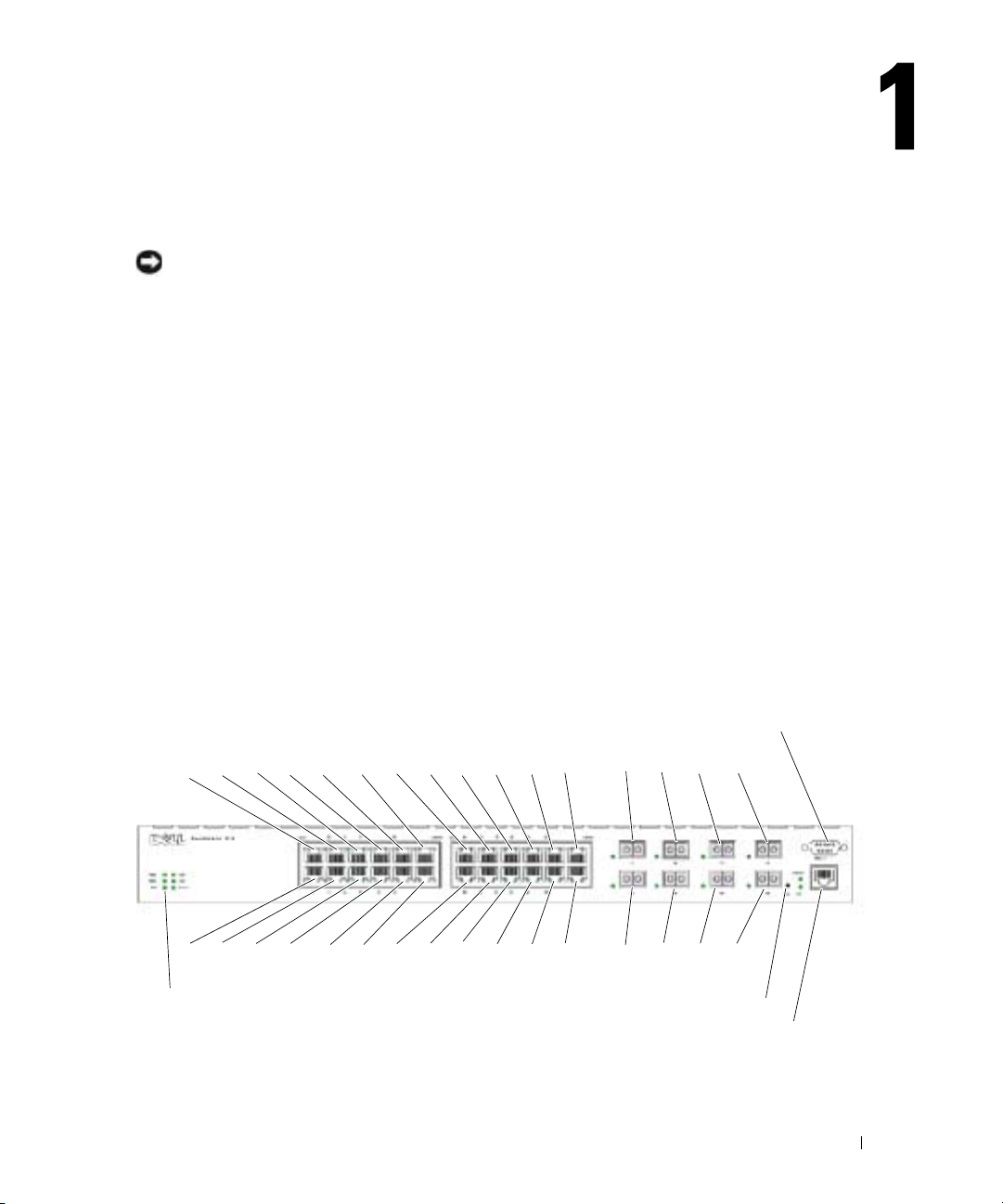
PowerConnect 6024
The PowerConnect 6024 provides 24 10/100/1000 Base-T RJ-45 ports with eight SFP combo ports
that have an auto-sensing mode for speed, flow control, and duplex mode. SFP transceivers are sold
separately.
Figure 1-1. PowerConnect 6024
C
o
n
s
o
l
e
(
R
S
-
2
3
2
B
a
s
e
-
T
P
o
r
t
s
5 973 11 13 15 17 19 21 23
S
F
P
P
o
r
t
s
17119 21 23
)
24681012141618202224 18202224
B
a
s
e
-
T
P
o
r
t
s
S
y
s
t
e
m
L
E
D
S
S
F
P
P
o
r
t
s
R
e
s
e
t
B
u
t
t
O
u
t
o
o
n
f
B
a
n
d
Introduction 23
Page 14
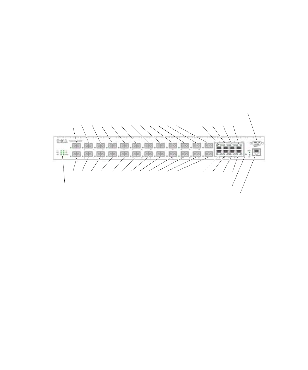
PowerConnect 6024F
PowerConnect 6024F provides 24 SFP ports with 8 10/100/1000 Base-T RJ-45 combo ports that
have an auto-sensing mode for speed, flow control, and duplex mode. SFP transceivers are sold
separately.
Figure 1-2. PowerConnect 6024F
CLI Documentation
www.dell.com | support.dell.com
The
switch. The document provides CLI descriptions, syntax, and default values.
1 59 3 11 13 15 17 19 21 23 17 19 21 23
2 4 6 8 1012141618202224 18 20 22 24
System LEDs
CLI Reference Guide
Console
7
SFP Ports
SFP Ports
Base-T Ports
Base-T Ports
Reset Button
(RS-232)
Out of Band
provides information about the CLI commands used to configure the
Features
This section describes the switch’s user-configurable features. For a list of all features, refer to the
software version release notes.
Port Based Features
Virtual Cable Testing (VCT)
VCT detects and reports potential copper link cabling issues, such as cable opens or cable shorts.
Jumbo Frames Support
Jumbo frames enables transporting identical data in fewer frames to ensure less overhead, lower
processing time, and fewer interrupts.
MDI/MDIX Support
Your switch supports auto-detection between crossed and straight-through cables.
24 Introduction
Page 15

Standard wiring for end stations is Media-Dependent Interface (MDI) and the standard wiring for
hubs and switches is known as Media-Dependent Interface with Crossover (MDIX).
For information about configuring MDI/MDI for ports or LAGs, see "Defining Port Configuration"
or "Defining LAG Configuration."
Hardware Watchdog Support
The switch uses Hardware Watchdog to detect issues and take corrective action when the software
stops responding.
Auto Negotiation
Auto negotiation allows the device to advertise modes of operation. The auto negotiation function
provides the means to exchange information between two devices that share a point-to-point link
segment, and to automatically configure both devices to take maximum advantage of their
transmission capabilities.
The PowerConnect 6024/6024F enhances auto negotiation by providing port advertisement. Port
advertisement allows the system administrator to configure the port speeds advertised.
For information about auto negotiation, see "Defining Port Configuration" or "Defining LAG
Configuration."
Flow Control Support (IEEE 802.3X)
Flow control enables lower speed devices to communicate with higher speed devices by requesting
that the higher speed device refrains from sending packets. Transmissions are temporarily halted to
prevent buffer overflows.
For information about configuring flow control for ports or LAGs, see "Defining Port
Configuration" or "Defining LAG Configuration."
Head of Line Blocking Prevention
Head of Line (HOL) blocking prevents traffic delays and frame loss caused by traffic competing for
the same egress port resources. HOL blocking queues packets, and the packets at the head of the
queue are forwarded before packets at the end of the queue.
Back Pressure Support
On half-duplex links, a receiver may prevent buffer overflows by occupying the link so that it is
unavailable for additional traffic.
For information about configuring Back Pressure for ports or LAGs, see "Defining Port
Configuration" or "Defining LAG Configuration."
Introduction 25
Page 16

MAC Address Supported Features
MAC Address Support
The switch supports up to 16K MAC addresses and reserves specific MAC addresses for system use.
Self-Learning MAC Addresses
The switch enables MAC addresses to be automatically learned from incoming packets.
Automatic Aging for MAC Addresses
MAC addresses that have not seen any traffic for a given period are aged out, which prevents the
Bridging Table from overflowing.
www.dell.com | support.dell.com
For information about configuring the MAC Address age-out period, see "Viewing Dynamic
Addresses."
Static MAC Entries
User-defined MAC entries are stored in the Bridging Table with the self-learned addresses.
For information about configuring the static MAC addresses, see "Defining Static Addresses."
VLAN-Aware MAC-based Switching
Packets arriving from an unknown source address are sent to the CPU and added to the Hardware
Table. Future Packets addressed to or from this address are more efficiently forwarded.
MAC Multicast Support
Multicast service is a limited broadcast service that allows one-to-many and many-to-many
connections. In Layer 2 multicast services, a single frame addressed to a specific multicast address
is received, and copies of the frame to be transmitted on each relevant port are created.
For information about configuring MAC Multicast Support, see "Multicast Forwarding Support."
Layer 2 Features
IGMP Snooping
IGMP Snooping examines the contents of IGMP frames when they are forwarded by the switch
from stations to an upstream multicast router. Snooping enables the switch to identify stations
interested in multicast sessions and which multicast routers are sending multicast frames.
For information about configuring IGMP Snooping, see "IGMP Snooping."
Port Mirroring
Port mirroring monitors and mirrors network traffic by forwarding copies of incoming and outgoing
packets from one port to a monitoring port.
26 Introduction
Page 17

For information about configuring port mirroring, see "Defining Port Mirroring Sessions."
Broadcast Storm Control
When Layer 2 frames are forwarded, broadcast and multicast frames are flooded to all ports on the
relevant VLAN. The flooding occupies bandwidth, and loads all nodes connected on all ports.
Storm control limits the amount of multicast and broadcast frames accepted and forwarded by the
switch.
For information about configuring storm control, see "Enabling Storm Control."
VLAN Supported Features
VLAN Support
VLANs are collections of switching ports that comprise a single broadcast domain. Packets are
classified as belonging to a VLAN based on either the VLAN tag or a combination of the ingress
port and packet contents. Packets sharing common attributes can be groups in the same VLAN.
For information about configuring VLANs, see "Configuring VLANs."
Port-Based VLANs
Port-based VLANs classify incoming packets to VLANs based on their ingress port.
For information about configuring VLANs, see "Configuring VLANs."
IEEE802.1V Protocol Based VLANs
VLAN classification rules are defined on data-link layer (Layer 2) protocol identification. Protocolbased VLANs are used for isolating Layer 2 traffic for differing Layer 3 protocols.
For information about defining Protocol Based VLANs, see "Defining VLAN Protocol Groups."
Full 802.1Q VLAN Tagging Compliance
IEEE 802.1Q defines an architecture for virtual bridged LANs, the services provided in VLANs, and
the protocols and algorithms involved in the provision of these services.
This standard requires an ability to mark frames with a desired Class of Service (CoS) tag
value (0-7).
GVRP Support
GARP VLAN Registration Protocol (GVRP) provides IEEE 802.1Q-compliant VLAN pruning and
dynamic VLAN creation on 802.1Q trunk ports. When GVRP is enabled, the switch registers and
propagates VLAN membership on all ports that are part of the active underlying Spanning Tree
protocol topology.
For information about configuring GVRP, see "Configuring GVRP. "
Introduction 27
Page 18

Private VLAN Edge
Private VLAN Edge (PVE) ports are a Layer 2 security feature that provides port-based security
between adjacent ports within a VLAN. It is an extension of the common VLAN. Traffic from
protected ports is sent only to the uplink ports and cannot be sent to other ports within the VLAN.
For information about configuring PVE ports, see "Configuring Ports".
Spanning Tree Protocol Features
Spanning Tree Protocol (STP) per Device
802.1d STP is a standard requirement of Layer 2 switches that allows bridges to automatically
www.dell.com | support.dell.com
prevent and resolve L2 forwarding loops. Switches exchange configuration messages, using
specifically formatted frames, and selectively enable and disable forwarding on ports.
For information about configuring STP, see "Configuring the Spanning Tree Protocol."
Fast Link
STP can take as long as 30-60 seconds to converge as it detects possible loops and allows time for
status changes to propagate and for relevant devices to respond. This duration is considered too
long for many applications. Fast Link bypasses this delay without requiring multiple data paths for
network resiliency.
For information about enabling Fast Link for ports and LAGs, see "Defining Port Configuration" or
"Defining LAG Configuration."
IEEE 802.1W Rapid Spanning Tree
Rapid Spanning Tree Protocol (RSTP) detects uses network topologies to enable faster
convergence, without creating forwarding loops.
For information about enabling RSTP, see "Defining the Rapid Spanning Tree."
Multiple Spanning Tree
Multiple Spanning Tree (MSTP) operation maps VLANs into ST instances. MSTP provides a
differing load balancing scenario. Packets assigned to various VLANs are transmitted along
different paths within MSTP Regions (MST Regions). Regions are one or more interconnected
MSTP bridges with identical MSTP settings. The standard lets administrators assign VLAN traffic
to unique paths.
For more information about MSTP, see "Defining the Multiple Spanning Tree".
28 Introduction
Page 19

Link Aggregation
Link Aggregation
Up to seven ports can combine to form a single Link Aggregated Group (LAG). This enables fault
tolerance protection from physical link disruption, higher bandwidth connections and improved
bandwidth granularity.
A LAG is composed of ports of the same speed, set to full-duplex operation.
For information about configuring LAGs, see "Defining LAG Configuration."
Link Aggregation and LACP
LACP uses peer exchanges across links to determine, on an ongoing basis, the aggregation
capability of various links, and continuously provides the maximum level of aggregation capability
achievable between a given pair of systems. LACP automatically determines, configures, binds, and
monitors the binding of ports to aggregators within the system.
For information about LACP, see "Defining LACP Parameters."
Routing Features
IP Routing
IP routing forwards to a next-hop device any packets that are addressed to the system MAC
addresses but not to a system IP address.
For information about configuring IP routing, see "Configuring Global IP Routing."
RIP Versions 1 and 2
Routing Information Protocol (RIP) is a distance-vector routing protocol. RIP selects routes based
on the hop count to the destination. RIP 2 enhances the efficiency, usability, and authentication
methods of the RIP protocol.
For information about configuring RIP, see "Configuring RIP."
OSPF Version 2
Open Shortest Path First (OSPF) is an internal gateway routing protocol. In networks with a large
number of inter-connected routers, OSPF is more efficient than RIP because OSPF uses less link
bandwidth and converges more quickly.
For information about configuring OSPF, see "Configuring OSPF Parameters and Filters."
Introduction 29
Page 20

Address Resolution Protocol (ARP)
In IP routing, routers and Layer 3 switches use various routing protocols to discover network
topology and define routing tables. ARP automatically determines Device Next-Hop MAC
addresses of systems, including directly attached end systems. Users can override and supplement
this by defining additional ARP table entries
.
For information about configuring ARP, see "Defining ARP Settings."
ICMP Messages
Internet Control Message Protocol (ICMP) messages are used for out-of-band messages related to
network operation or malfunction.
www.dell.com | support.dell.com
IGMPv2
IGMP enables the router to send IGMP queries in the form of L2 broadcasts over each interface.
When a multicast packet is sent, and it has a multicast destination MAC address, all hosts on that
router interface receive a copy. Hosts listen to all IGMP reports. If interested multicast groups have
already been requested by any station on the same interface, the remaining stations do not send
duplicate requests.
For information about configuring IGMP, see "Defining IGMP Interface Parameters."
Longest Prefix Match Support
Longest prefix matches are used primarily to determine the best next-hop route for a packet based
solely on the destination address contained in the packet header. Because IP addresses are generally
assigned in a manner that reflects the topology of the network, the result of a longest prefix match
usually reflects the shortest route to the destination.
DVMRP
Distance Vector Multicast Routing Protocol (DVMRP) advertises the shortest-path routes to
multicasting source networks with hosts that can transmit multicast IP traffic.
For information about configuring DVMRP, see "Configuring DVMRP Interfaces."
VRRP
Virtual Router Redundancy Protocol (VRRP) eliminates single points of failure in the routing
environment. VRRP uses an election protocol that dynamically assigns responsibility for the virtual
router to one of the VRRP routers in the LAN.
The election process provides dynamic failover in the forwarding responsibility, if the master is
unavailable. Any virtual router IP address can be used as a default first-hop router by end-hosts.
For information about configuring VRRP, see "Configuring VRRP."
30 Introduction
Page 21

Layer 3 Features
TCP
Transport Control Protocol (TCP) connections are defined between 2 ports by an initial
synchronization exchange. TCP ports are identified by an IP address and a 16-bit port number.
Octets streams are divided into TCP packets, each carrying a sequence number.
UDP Relay
UDP Relay enables the device to forward specific UDP broadcasts from one interface to another. IP
broadcast packets from one interface are not generally forwarded to another interface. However,
some applications use UDP broadcast to detect the availability of a service. Other services require
UDP broadcast packets to be routed to provide services to clients on another subnet.
BootP and DHCP Clients
DHCP enables additional setup parameters to be received from a network server upon system
startup. DHCP service is an on-going process. DHCP is an extension to BootP.
For information about DHCP, see "Defining DHCP IP Interface Parameters."
BootP Relay
BootP enables a device to solicit and receive configuration data from servers. If the intended BootP
server is not directly attached to a client’s broadcast domain, a BootP relay service enables the
client to reach the server.
DHCP Relay
DHCP enables a device to solicit and receive configuration data from servers. If the intended
DHCP server is not directly attached to a client’s broadcast domain, a DHCP relay service enables
the client to reach the server.
For information about configuring DHCP Relay parameters, see "Defining DHCP Relay
Parameters."
Quality of Service Features
Quality of Service (QoS) Support
To overcome unpredictable network traffic and optimize performance, you can apply Quality of
Service (QoS) throughout the network to ensure that network traffic is prioritized according to
specific criteria. Your switch supports two modes of QoS: basic and advanced.
Introduction 31
Page 22

Class Of Service 802.1p Support
The IEEE 802.1p signaling technique is an OSI Layer 2 standard for tagging and prioritizing
network traffic at the data link/MAC sub-layer. The 802.1p traffic is classified and sent to the
destination; no bandwidth reservations or limits are established or enforced. The 802.1p standard
establishes eight levels of priority, similar to the IP Precedence IP Header bit-field.
Quality of Service Basic Mode
In basic QoS mode, it is possible to activate a trust mode (to trust VPT, DSCP, TCP/UDP or none).
In addition, a single access control list can be attached to an interface.
For information about enabling QoS Basic Mode, see "Configuring Basic QoS Mode."
www.dell.com | support.dell.com
Quality of Service Advanced Mode
Advanced Quality of Service mode specifies flow classification and assigns rule actions that relate
to bandwidth management. These rules can be grouped into a policy, which can be applied to an
interface.
For information about enabling QoS Advanced Mode, see
Device Management Features
SNMP Alarms and Trap Logs
The system logs events with severity codes and timestamps. The events are sent as SNMP traps to a
trap recipient list.
For information about SNMP Alarms and Traps, see "Defining SNMP Parameters."
Web Based Management
You can manage the system from any web browser. The switch contains an embedded web server
that serves HTML pages that you can use to monitor and configure the system.
Configuration File Download
The switch’s configuration file includes both system-wide and port-specific device configuration
data. You can display configuration files through CLI commands.
For information about downloading configuration files, see "Downloading Files."
"
Configuring Advanced QoS Mode."
Software Download
Software download enables storage of backup firmware images. For information about downloading
the software, see
32 Introduction
"
Software Download and Reboot."
Page 23

Trivial File Transfer Protocol (TFTP)
PowerConnect 6024/6024F supports boot image, firmware and configuration upload/download via
TFTP.
Remote Monitoring
Remote monitoring (RMON) is an extension to the SNMP that provides comprehensive network
traffic
monitoring capabilities (as opposed to SNMP, which allows network
device
management and
monitoring). RMON is a standard MIB that defines current and historical MAC-layer statistics and
control objects, allowing real-time information to be captured across the entire network.
For information about RMON, see
Simple Network Management Protocol (SNMP) Versions 1, 2 and 3
"
Viewing RMON Statistics."
To control access to the system, a list of community entries is defined, each of which consists of a
community string and its access privileges. There are three levels of SNMP security — read-only,
read-write, and super. Only a super-user can access the community table itself.
Command Line Interface
Command Line Interface (CLI) syntax and semantics conform as much as possible to common
industry practice. CLI is composed of mandatory and optional elements. Context-sensitive help
provides format and value ranges allowed for current commands, and the CLI interpreter provides
command and keyword completion.
Syslog
Syslog is a protocol that allows event notifications to be sent to a set of desired remote servers
where they can be stored, examined, and acted upon.
For information about Syslog, see
"
Managing Logs."
SNTP
The Simple Network Time Protocol (SNTP) assures accurate network switch clock time
synchronization up to the millisecond. Time synchronization is performed by a network SNTP
server.
For more information about SNTP, see "Configuring SNTP Settings."
Traceroute
Traceroute enables discovering IP routes that packets were forwarded along during the forwarding
process. The CLI Traceroute utility can be executed from either User EXEC or Privileged EXEC
modes.
Introduction 33
Page 24

Out-of-Band Management Port Support
An out-of-band management port is an external Ethernet port that carries only traffic between the
system-administrator and the management applications. The out-of-band management port
provides a physically secure link and also offers fault tolerance.
Security Features
Access Control Lists (ACL)
ACL provides rules for forwarding or blocking network traffic. You can define ACLs to enforce
security enhancements by defining classification rules and assigning an action per rule. You can
assign an ACL to an ingress interface (port or VLAN).
www.dell.com | support.dell.com
For information about defining ACLs, see "Defining IP based ACLs" and "Defining MAC based
ACLs."
Port Based Authentication (802.1x)
Port based authentication enables authenticating system users on a per port basis via an external
server. Only authenticated and approved system users can transmit and receive data. Ports are
authenticated via the Remote Authentication Dial In User Service (RADIUS) server using the
Extensible Authentication Protocol (EAP).
For more information, see "Configuring Port Based Authentication."
Locked Port Support
Locked port limits access on a port only to users with specific MAC addresses. These addresses are
manually defined or learned on that port. When a frame is seen on a locked port, and the frame
source MAC address is not tied to that port, the protection mechanism is invoked.
For information about enabling locked port security, see
"
Configuring Port Security."
Password Management Security
Password management provides increased network security and improved password control.
Passwords for SSH, Telnet, HTTP, HTTPS and SNMP access are assigned security features.
For more information about password management, see "Managing Passwords".
TACACS+
TACACS+ provides centralized security for validation of users accessing the switch. TACACS+
provides a centralized user management system, while still retaining consistency with RADIUS and
other authentication processes.
For information about defining TACACS+ settings, see "Configuring Out-of-Band TACACS+
Servers" and "Configuring TACACS+ Settings."
34 Introduction
Page 25

RADIUS Client
RADIUS is a client/server-based protocol in which the server maintains a user database, that
contains per-user authentication information, such as user name, password and accounting
information.
For information about defining RADIUS settings, see "Configuring RADIUS Settings."
SSH
Secure Shell (SSH) is a protocol that provides a secure, remote connection to a device. This
connection provides functionality that is similar to an inbound telnet connection.
Introduction 35
Page 26

www.dell.com | support.dell.com
36 Introduction
Page 27
Hardware Description
This section contains information about device characteristics and module hardware
configurations.
Ports Description
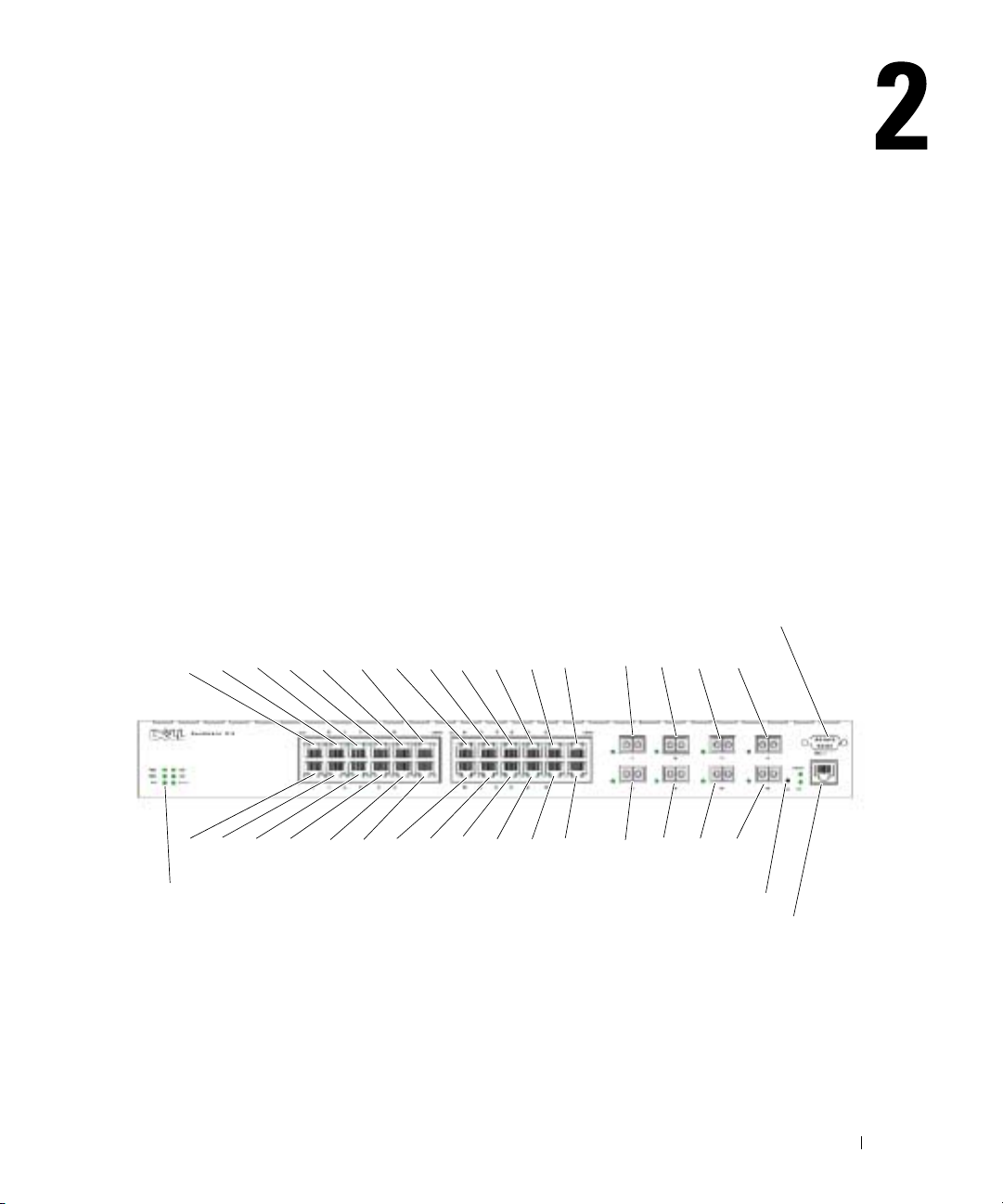
PowerConnect 6024
Ports 1-16 are designated as 10/100/1000 ports, and ports 17-24 are designated as combo ports. The
port numbers are shown in the figure below.
A combo port is a single logical port with two physical connections — an RJ-45 connection and a
SFP connection. When a connector is inserted in the SFP port, the SFP port is active, unless a
Base-T port copper connector of the of the same number is inserted and has a link.
Figure 2-1. PowerConnect 6024 with 24 10/100/1000 Base-T Ports
C
o
n
s
o
l
e
(
R
S
-
2
3
2
B
a
s
e
-
T
P
o
r
t
s
5 973 11 13 15 17 19 21 23
S
F
P
P
o
r
t
s
17119 21 23
)
24681012141618202224 18202224
B
a
s
e
-
T
P
o
r
t
s
S
y
s
t
e
m
L
E
D
S
S
F
P
P
o
t
r
s
R
e
s
e
t
B
u
t
t
o
n
O
u
t
o
f
B
a
n
d
The switch automatically detects the difference between crossed and straight through cables on
RJ-45 ports. SFP ports support both SX and LX modules.
RJ-45 ports support half- and full-duplex mode 10/100/1000 Mbps.
Hardware Description 37
Page 28
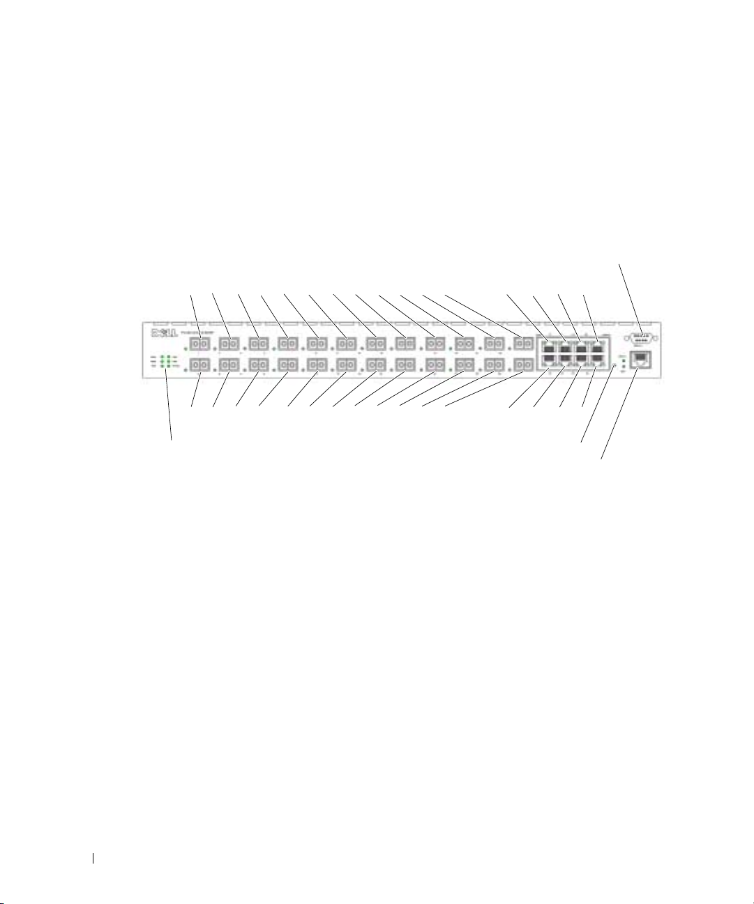
PowerConnect 6024F
The PowerConnect 6024F ports differ from the PowerConnect 6024 only in port designation:
Ports 1-16 are designated as SFP ports, and ports 17-24 are designated as combo ports. The port
numbers are shown in the figure below.
For information about how the ports function, see the port description for the PowerConnect 6024.
Figure 2-2. PowerConnect 6024F with 24 SFP Ports
www.dell.com | support.dell.com
1 59 3 11 13 15 17 19 21 23 17 19 21 23
2 4 6 8 10 12 14 16 18 20 22 24 18 20 22 24
System LEDs
Out-of-Band Management Port
The Out-of-Band (OOB) management port is a 10/100 Mbps Ethernet port that you can use to
connect directly to the switch to perform system administrator management applications. The
Out-of-Band port is regarded as a regular IP interface to the system, and all management interfaces
are available over this port.
For more information about configuring Out-of-Band, see "Out-of-Band Management Port."
Console
7
SFP Ports
SFP Ports
Base-T Ports
Base-T Ports
Reset Button
(RS-232)
Out of Band
Console (RS-232) Port
The console (RS-232) port is used only for management via a serial interface. This port is a direct
connection to the switch, used to access CLI from a console terminal connected to an EIA/TIA-232
port.
The console port supports synchronous data of eight data bits, one stop bit, and no parity bit. The
default baud rate is 115,200 bps.
38 Hardware Description
Page 29
Hardware Components
Physical Dimensions
The switch has the following physical dimensions:
• 440 x 460 x 44 mm (W x D x H).
• 17.32 x 18.11 x 1.73 inch (W x D x H).
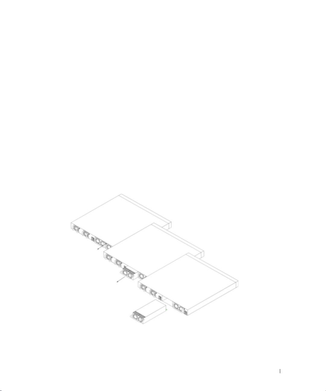
Power Supplies
Your switch is shipped with two internal power supplies. You can verify operation by observing the
LEDs. See "System LEDs" for information.
To replace a power supply:
1
Remove the faulty power supply unit by removing its screw in the back panel and pulling it
out.
2
Insert a new power supply into the slot, ensuring that the power supply is inserted fully into
the switch.
Figure 2-3. Power Supply Insertion
1
2
3
Insert and tighten the screw to the power supply.
4
Connect each power supply to a different external power source.
Hardware Description 39
Page 30
When you connect to a different power source, the probability of the switch failing in the
event of a power outage decreases.
Reset Button
The reset button, located on the front panel, manually resets the switch.
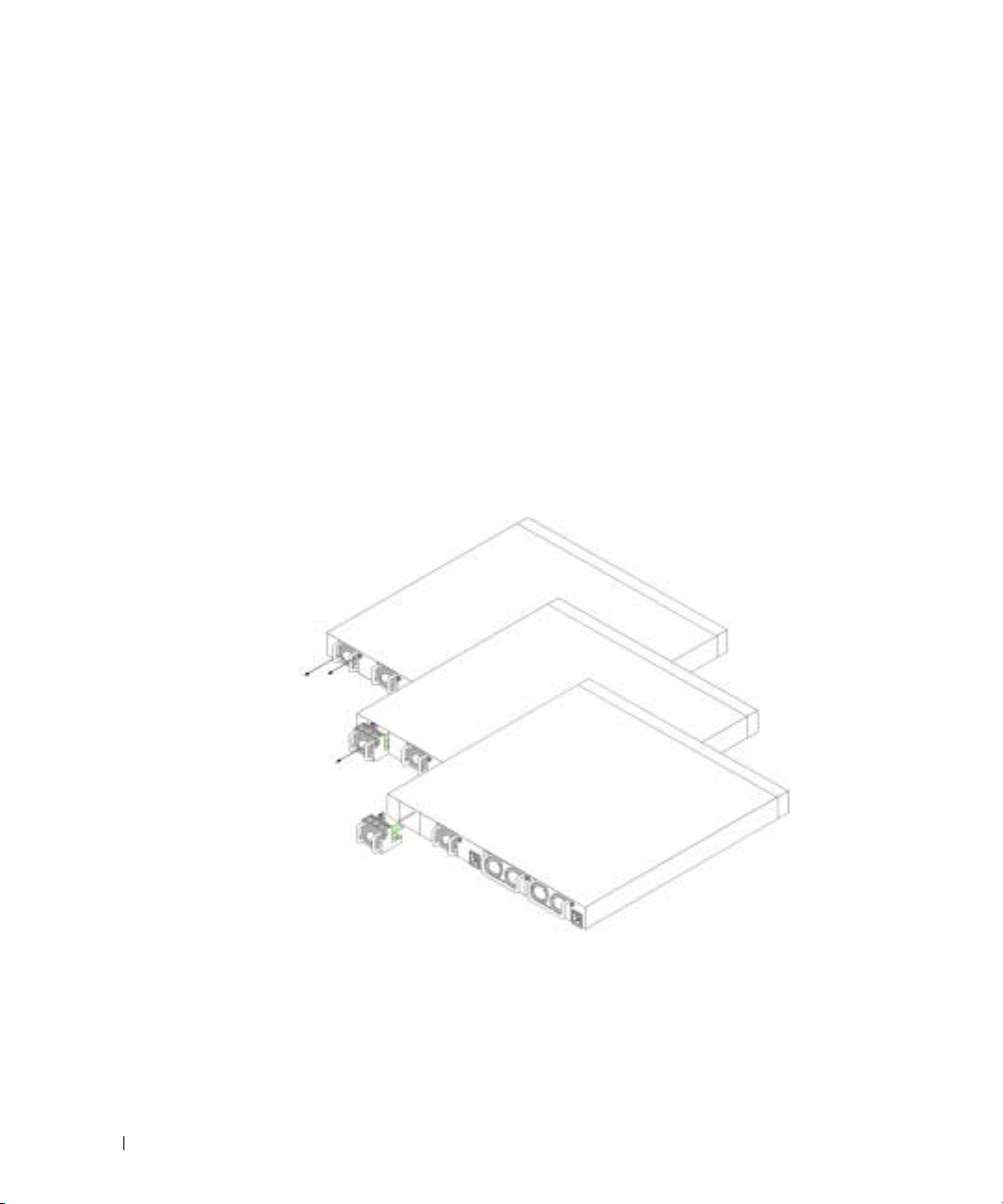
Ventilation System
There are two fans in the system. You can verify operation by observing the LEDs. See "System
LEDs" for information.
To replace a fan:
1
www.dell.com | support.dell.com
Remove the two screws, and gently pull out the faulty fan.
2
Carefully insert the new fan into the slot.
Figure 2-4. Fan Installment/Replacement
3
Insert and tighten the screw to the fan.
LED Definitions
The front panel contains light emitting diodes (LED) that indicate the status of links, power
supplies, fans, and system diagnostics.
40 Hardware Description
1
2
Page 31

SFP Port LEDs
Figure 2-5 illustrates the SFP port LEDs that are next to each SFP port.
Figure 2-5. SFP Port LEDs
SFP Port 17
SFP LEDs
SFP Port 18
Table 2-1 contains SFP port LED definitions:
Table 2-1. SFP Port LEDs Definitions
LED Color Definition
SFP Green The port is currently linked.
Flashing Green The port is currently sending and/or
receiving network traffic.
Off The port is currently not linked.
10/100/1000 Base-T Port LEDs
Each 10/100/1000 Base-T port has two LEDs. The speed LED is located on the left side of the port,
while the link/duplex/activity LED is located on the right side. The following figure illustrates the
10/100/100 Base-T port LEDs:
Figure 2-6. 10/100/1000 Base-T Port LEDs
Port 1
Speed LEDs
Port 2
Link/Duplex/Activity
LEDs
Hardware Description 41
Page 32

Table 2-2 contains 10/100/1000 Base-T port LED definitions.
Table 2-2. 10/100/1000 Base-T Port Definitions
LED Color Definition
Speed
Link
www.dell.com | support.dell.com
Green The port is operating at 1000 Mbps.
Amber The port is operating at 100 Mbps.
Off The port is operating at 10 Mbps.
Green The port is running, and the full
duplex mode is active.
Flashing Green The port is sending or receiving
packets, and running full duplex
mode.
Amber The port is running, and the half
duplex mode is active.
Flashing Amber The port is sending or receiving
packets, and running half duplex
mode.
Off The port is not linked.
System LEDs
The system LEDs, located on the left side of the front panel, provide information about the power
supplies, fans, thermal conditions, and diagnostics.
Figure 2-7 illustrates the System LEDs.
42 Hardware Description
Page 33

Figure 2-7. System LEDs
Table 2-3 contains system LED definitions.
Table 2-3. System LED Definitions
LED Color Definition
Fan 1
Green Fan 1 is present and operating.
Red Fan 1 is present, but not operating.
Off Fan 1 is not present.
Fan 2
Green Fan 2 is present and operating.
Red Fan 2 is present, but not operating.
Off Fan 2 is not present.
PWR1
Green Power Supply 1 is present and
operating.
Red Power Supply 1 is present, but not
operating.
Off Power Supply 1 is not present.
Hardware Description 43
Page 34

Table 2-3. System LED Definitions
LED Color Definition
PWR2
Dia (Diagnostic)
www.dell.com | support.dell.com
Thermal
Green Power Supply 2 is present and
operating.
Red Power Supply 2 is present, but not
operating.
Off Power Supply 2 is not present.
Flashing Green A diagnostics test is currently in
progress.
Green The diagnostics test was successfully
completed.
Red The diagnostics test failed.
Red The system has exceeded the
maximum temperature.
Off The system temperature is normal.
44 Hardware Description
Page 35

Cable, Port, and Pinout Information
This section describes the switch’s physical interfaces and provides information about cable
connections.
Stations are connected to the switch’s ports through the physical interface ports on the front panel.
For each station, the appropriate mode (Half/Full Duplex, Auto) is set.
Pin Connections for the 10/100/1000 Ethernet Interface
The switching port can connect to stations wired in standard RJ-45 Ethernet station mode using
straight cables. Transmission devices connected to each other use crossed cables.
Figure 3-1 illustrates the RJ-45 pins, and Table 3-1 contains the RJ-45 pin allocations.
Figure 3-1. RJ-45 Connector
Table 3-1. RJ-45 Pin Connections for 10/100/1000 Base T
Pin Use
1 TxRx 1+
2 TxRx 1-
3 TxRx 2+
Cable, Port, and Pinout Information 45
Page 36

Table 3-1. RJ-45 Pin Connections for 10/100/1000 Base T
Pin Use
4TxRx 2-
5 TxRx3+
6TxRx 3-
7TxRx 4+
8TxRx 4-
Pin Connections for SFP Interfaces
www.dell.com | support.dell.com
Figure 3-2 illustrates an SFP connector, and Table 3-2 shows the pin assignments for an optional
SFP connector.
Figure 3-2. SFP Connector
Table 3-2. SFP Pin Connections
Pin Use
1 Transmitter ground (common with
receiver ground)
2 Transmitter fault
3 Transmitter disable; laser output disabled
on high or open
4 Module definition 2; data line for serial ID.
5 Module definition 1; clock line for
serial ID.
46 Cable, Port, and Pinout Information
Page 37

Table 3-2. SFP Pin Connections
Pin Use
6 Module definition 0; grounded within the
module
7 Rate select; no connection required.
8 Loss of signal indication; logic 0 indicates
normal operation.
9 Receiver ground (common with
transmitter ground)
10 Receiver ground (common with
transmitter ground)
11 Receiver ground (common with
transmitter ground)
12 Receiver inverted data out; AC coupled.
13 Receiver non-inverted data out; AC
coupled.
14 Receiver ground (common with
transmitter ground)
15 Receiver power supply
16 Transmitter power supply
17 Transmitter ground (common with
receiver ground)
18 Transmitter non-inverted data in
19 Transmitter inverted data in
20 Transmitter ground (common with
receiver ground).
Serial Cable Connection
You can use serial cables (null-modem) to connect the switch to a terminal for initial setup and
configuration (You can also use a PC running terminal emulation software.). The switch’s serial
cable is female to female DB-9 crossover cable (see Figure 3-3).
Figure 3-3 shows the serial cable and Table 3-3 shows the serial connector pin assignments.
Cable, Port, and Pinout Information 47
Page 38

Figure 3-3. Serial Connector
www.dell.com | support.dell.com
Table 3-3 contains serial cable pin assignments.
Table 3-3. Serial Connector Pin Assignment
Signal Pin Management Console Port Signal
Unused 1 Unused
TXD 2 TXD
RXD 3 RXD
Unused 4 RXD
GND 5 GND
Unused 6 Unused
CTS 7 CTS
RTS 8 RTS
Unused 9 Unused
1
6
5
9
Connecting the Switch to a Terminal
1
Connect the null modem (serial) cable to the terminal (console) ASCII DTE RS-232
connection.
2
Connect the interface cable to the switch’s serial port connection (see Figure 3-4).
48 Cable, Port, and Pinout Information
Page 39

Figure 3-4. Serial Connection to Switch
To Console
AC Power Connection
1
Using a 5-foot (1.5 m) standard power cable with safety ground connected, connect the power
cable to the AC main socket located on the rear panel (see Figure 3-5).
2
Connect the power cable to a grounded AC outlet.
NOTE: It is recommended that you connect the second power supply to a different power source.
3
Confirm that the device is connected and operating correctly by examining the LEDs on the
front and rear panel.
For a complete explanation of the LEDs, see "Hardware Description."
4
Repeat the procedure for the second power supply.
Cable, Port, and Pinout Information 49
Page 40

Figure 3-5. AC Power Connection to Switch
www.dell.com | support.dell.com
50 Cable, Port, and Pinout Information
Page 41

Using Dell OpenManage Switch Administrator
Starting the Application
1
Open a web browser.
2
Enter the switch’s IP address (as defined in the CLI) in the address bar and press <Enter>.
For information about assigning an IP address to a switch, see "Initial Configuration."
3
When the
NOTE: The switch is not configured with a default password, and you can configure the switch without
entering a password. For information about recovering a lost password, see "Password Recovery."
NOTE: Passwords are both case sensitive and alpha-numeric.
Click OK.
4
5
The
Understanding the Interface
The home page (see Figure 4-1) contains the following views:
•
Tree view
view of features and their components.
•
Device view
the device, an information or table area, and configuration instructions.
Enter Network Password
Dell OpenManage Switch Administrator
— Located on the left side of the home page, the tree view provides an expandable
— Located on the right side of the home page, the device view provides a view of
window displays, enter a user name and password.
home page displays.
Using Dell OpenManage Switch Administrator 51
Page 42

Figure 4-1. Switch Administrator Components
www.dell.com | support.dell.com
1
Table 4-1 lists the interface components with their corresponding numbers.
Table 4-1. Interface Components
4
2
3
Component Name
1 The tree view contains a list of various device
features. The branches in the tree view can be
expanded to view all the components under a
specific feature, or retracted to hide the feature's
components. By dragging the vertical bar to the
right, you can expand the tree area to view a full
name of a component.
52 Using Dell OpenManage Switch Administrator
Page 43

Table 4-1. Interface Components
Component Name
2 The device view provides information about
device ports, current configuration and status,
table information, and feature components.
The port coloring indicates if a port is currently
active. Green indicates the port is enabled, red
indicates that an error has occurred on the port,
and blue indicates that the link is disabled.
NOTE: The LEDs do not appear in the device view.
You can only determine LED status by looking at
the actual switch. For information about LEDs, see
"LED Definitions."
Depending on which option you select, the area
at the bottom of the device view displays other
device information and/or dialogs for configuring
parameters.
3 The components list contains a list of feature
components. You can also view components by
expanding a feature in the tree view.
4 The information buttons provide access to
information about the switch and access to Dell
Support. For more information, see "Information
Buttons."
Using the Switch Administrator Buttons
Information Buttons
Table 4-2. Information Buttons
Button Description
Support Opens the Dell Support page at
support.dell.com
Help Online help that contains information to assist
in configuring and managing the switch. The
online help pages are linked directly to the pages.
For example, if the IP Addressing page is open,
the help topic for that page displays if you click
Help.
Using Dell OpenManage Switch Administrator 53
Page 44

Table 4-2. Information Buttons
Button Description
About Contains the version and build number and Dell
copyright information.
Log Out Logs out of the application and closes the
browser window.
Device Management Buttons
Table 4-3. Device Management Buttons
www.dell.com | support.dell.com
Button Description
Apply Changes Applies set changes to the device.
Add Adds information to tables or dialogs.
Te ln e t Starts a Telnet session.
Query Queries tables.
Show All Displays the device tables.
Left arrow/Right arrow Moves information between lists.
Refresh Refreshes device information.
Reset All Counters Clears statistic counters.
Print Prints the Network Management System page and/or
Show Neighbor’s Info Displays the Neighbors List from the Neighbors Table
Draw Creates statistics charts on-the-fly.
Clear Log Clears log messages from the log buffer.
Reset Resets the switch.
Test Now Runs diagnostic test for copper cables.
Defining Fields
table information.
page.
User-defined fields can contain 1-159 characters, unless otherwise noted on the Dell OpenManage
Switch Administrator Web page.
All characters may be used except for the following:
•\
•/
•:
54 Using Dell OpenManage Switch Administrator
Page 45

•*
•?
•<
•>
•|
Accessing the Switch Through the CLI
The switch can be managed over a direct connection to the console port or via a Telnet connection.
For information about out-of-band management ports, see
Using the CLI is similar to entering commands on a Linux system. If access is via a Telnet
connection, ensure the device has an IP address defined and that the workstation used to access the
device is connected to the device prior to beginning using CLI commands.
For information about configuring an initial IP Address, see "Initial Configuration."
NOTE: Ensure the client is loaded, before using the CLI.
Console Connection
1
Power on the switch and wait until the startup is complete.
2
When the
3
Configure the device and enter the necessary commands to complete the required tasks.
4
When finished, exit the session with the
Console>
prompt displays, type
quit
enable
"
Out-of-Band Management Port."
and press <Enter>.
or
exit
command.
NOTE: If a different user logs into the system in the Privilege EXEC command mode, the current user is
logged off and the new user is logged in.
Telnet Connection
Telnet is a terminal emulation TCP/IP protocol. ASCII terminals can be virtually connected to the
local device through a TCP/IP protocol network. Telnet is an alternative to a local login terminal
where a remote login is required.
Your switch supports up to four simultaneous Telnet sessions. All CLI commands can be used over
a telnet session.
To start a Telnet session:
1
Select
Start > Run
2
In the
Run
window, type
3
Click OK to begin the Telnet session.
.
Telnet
<IP address
>
in the
Open
field.
Using Dell OpenManage Switch Administrator 55
Page 46

Using the CLI
Command Mode Overview
The CLI is divided into command modes. Each command mode has a specific command set.
Entering a question mark at the console prompt displays a list of commands available for that
particular command mode.
In each mode, a specific command is used to navigate from one command mode to another.
During the CLI session initialization, the CLI mode is the User EXEC mode. Only a limited subset
of commands are available in the
change the console configuration and is used to access configuration sub-systems such as the CLI.
www.dell.com | support.dell.com
To enter the next level, the Privileged EXEC mode, a password is required (if configured).
The
Privileged EXEC mode provides access to the device global configuration. For specific global
configurations within the device, enter the next level, Global Configuration mode. A password is
not required.
The
Global Configuration mode manages the device configuration on a global level.
The Interface Configuration mode configures the device at the physical interface level. Interface
commands which require subcommands have another level called the Subinterface Configuration
mode. A password is not required.
User EXEC Mode
After logging into the device, the EXEC command mode is enabled. The user-level prompt consists
of the host name followed by the angle bracket (>). For example:
console>
User EXEC mode. This level is reserved for tasks that do not
NOTE: The default host name is console unless it has been modified during initial configuration.
The user EXEC commands permit connecting to remote devices, changing terminal settings on a
temporary basis, performing basic tests, and listing system information.
To list the user EXEC commands, enter a question mark at the command prompt.
Privileged EXEC Mode
Privileged access can be protected to prevent unauthorized access and ensure operating parameters.
Passwords are displayed on the screen, and are case sensitive.
To access and list the Privileged EXEC Mode commands:
1
At the prompt type
2
When a password prompt displays, enter the password and press <Enter>.
The Privileged EXEC mode prompt displays as the device host name followed by #. For
example:
console#
56 Using Dell OpenManage Switch Administrator
enable
and press <Enter>.
Page 47

To list the Privileged EXEC commands, type a question mark at the command prompt and
press <Enter>.
To return from Privileged EXEC Mode to User EXEC Mode use any of the following
commands:
The following example illustrates accessing privileged EXEC mode and then returning to the User
EXEC mode:
console>enable
Enter Password: ******
console#
console#disable
console>
disable, exit/end
, or <Ctrl><Z>.
Use the
Interface Configuration mode to Global Configuration mode, and from Global Configuration
mode to Privileged EXEC mode.
exit
command to move back to a previous mode. For example, you can move from
Global Configuration Mode
Global Configuration commands apply to system features, rather than a specific protocol or
interface.
To access Global Configuration mode, at the Privileged EXEC Mode prompt, type
and press <Enter>. The Global Configuration Mode displays as the device host name followed by
the pound sign # and (config).
console(config)#
To list the Global Configuration commands, enter a question mark at the command prompt.
To return from Global Configuration mode to Privileged EXEC mode, type the
use the <Ctrl><Z> command.
The following example illustrates how to access
Privileged EXEC Mode
console#
console#configure
console(config)#exit
console#
:
Global Configuration Mode
and return back to the
configure
exit
command or
Using Dell OpenManage Switch Administrator 57
Page 48

Interface Configuration Mode
Interface configuration commands modify specific IP interface settings, including bridge-group,
description, and so forth. The
•
VLAN
— Contains commands to create and configure a VLAN as a whole, for example, to
create a VLAN and apply an IP address to the VLAN.
•
Port Channel
•
IP
—
Contains commands for managing IP interfaces.
Out-of-Band-Ethernet — Contains commands for managing and configuring the
•
management connections.
— Contains commands for configuring Link Aggregation Groups (LAG).
Interface Configuration modes are:
www.dell.com | support.dell.com
CLI Examples
CLI commands are provided as configuration examples. For a full description of the CLI
commands, including examples, refer to your switch’s
CLI Reference Guid
e.
58 Using Dell OpenManage Switch Administrator
Page 49

Configuring the Switch
This section describes the initial device configuration.
After completing all external connections, you must connect a terminal to the device to monitor
the boot and other procedures. The order of installation and configuration procedures is illustrated
in Figure 5-1. For the initial configuration, the standard device configuration is performed. You can
perform other functions, but doing so suspends the installation process and causes a system reboot.
Performing other functions is described later in this section.
NOTICE: Before proceeding, read the release notes for this product. You can download the release
notes from support.dell.com.
Configuring the Switch 59
Page 50

Figure 5-1. Installation and Configuration Jobflow
www.dell.com | support.dell.com
Press Esc
Startup Menu
(Special functions)
Reboot
Connect Device and
Yes
Loading program from
Initial Configuration: IP
Address, Subnetmask,
Users Basic Security
configuration
Console
Power on
S
u
s
p
e
n
d
flash to RAM
Enter Wizard
Hardware
Setup
B
o
o
t
u
p
No
Yes
No
Wizard Configuration
Process
Standard
Device
Installation
60 Configuring the Switch
Advanced Configuration:
IP Address from DHCP,
IP Address from bootp,
Security management
Advanced
Device
Installation
Page 51

General Configuration Information
Your switch has predefined features and setup configuration.
Auto-Negotiation
Auto-negotiation allows a device to advertise modes of operation and share information with
another device that shares a point-to-point link segment. This automatically configures both
devices to take maximum advantage of their abilities.
Auto-negotiation is performed completely within the physical layers during link initiation, without
any additional overhead to either the MAC or higher protocol layers. Auto-negotiation allows the
ports to do the following:
• Advertise their abilities
• Acknowledge receipt and understanding of common modes of operation that both devices
share
• Reject the use of operational modes that are not shared by both devices
• Configure each port for the highest-level operational mode that both ports can support
If connecting a port of the switch to the network interface card (NIC) of a workstation or server
that does not support auto-negotiation or is not set to auto-negotiation, both the switching port
and the NIC must be manuallyet with the Web browser interface or CLI commands to the same
speed and duplex mode.
NOTICE: If the station on the other side of the link attempts to auto-negotiate with a port that is
manually configured to full duplex, the auto-negotiation results in the station attempting to operate in half
duplex. The resulting mismatch may lead to significant frame loss. This is inherent in the auto-negotiation
standard.
Switching Port Default Settings
The following table describes the switch port default settings.
Table 5-1. Port Default Settings
Function Default Setting
Port speed and mode 1000M Auto-negotiation
Port forwarding state Enabled
Head of line blocking prevention On (Enabled)
Flow Control Off
Back Pressure Off
Configuring the Switch 61
Page 52

The following is an example for changing the port speed on port g1 using CLI commands:
Console (config)# interface ethernet g1
Console (config-if)# speed 100
The following is an example for enabling flow control on port g1 using CLI commands:
Console (config)# interface ethernet g1
Console (config-if)# flowcontrol on
The following is an example for enabling back pressure on port g1 using CLI commands.
Backpressure works only for the 10-Mbps mode of operation.
Console (config)# interface ethernet g1
www.dell.com | support.dell.com
Console (config-if)# speed 10
Console (config-if)# back-pressure
Terminal Connection Configuration
Your switch requires the following Terminal Connection parameters for configuration:
• no parity
• one stop bit
• 8 data bits
Baud Rate
The baud rates can be manually changed to any of the following values:
• 2400
• 4800
• 9600
• 19200
• 115,200
NOTE: The default baud rate is 115,200.
NOTE: Closing the device does not return the default baud rate. It must be specifically configured.
NOTE: The baud rate setting of the console is not saved in the general configuration file of the switch. It
is directly stored in the non-volatile memory device of the switch.
The following is an example configuration for changing the default baud rate using CLI
commands:
console# configure
console(config)# line console
console(config-line)# speed 115200
62 Configuring the Switch
Page 53

Other Configuration Requirements
The following is required for downloading embedded software and configuring the device:
• ASCII terminal (or emulation) connected to the serial port (cross-cable) in the front of the
unit
• Assigned IP address for the switch for device remote control use with Telnet, SSH, and so
forth
NOTE: The configuration process defines only one port.
Booting the Switch
When the power is turned on with the local terminal already connected, the switch goes through
Power On Self Test (POST). POST runs every time the device is initialized and checks hardware
components to determine if the device is fully operational before completely booting.
If a critical problem is detected, the program flow stops. If POST passes successfully, a valid
executable image is loaded into RAM.
POST messages are displayed on the terminal and indicate test success or failure.
To boot the switch, perform the following steps:
1
Ensure that the ASCII cable is connected to the terminal.
2
Connect the power supply to the switch.
3
Power on the switch.
As the switch boots, the bootup test first counts the device memory availability and then
continues to boot. The following screen is an example of the displayed POST:
Boot1 Checksum Test...............................PASS
Boot2 Checksum Test...............................PASS
Flash Image Validation Test.......................PASS
Testing CPU PCI Bus Device Configuration..........PASS
BOOT Version 1.0.0.13 Date 13-Aug-2003 Time 15:28:31
Autoboot in 2 seconds - press RETURN or Esc. to abort and enter
prom.
The boot process runs approximately 30 seconds.
The auto-boot message that appears at the end of POST (see the last lines) indicates that no
problems were encountered during boot.
Configuring the Switch 63
Page 54

During boot, you can use the
Startup
menu, press <Esc> or <Enter> within the first two seconds after the auto-boot message
appears. For information on the
Startup
Startup
menu, if necessary to run special procedures. To enter the
menu, see "Startup Menu Functions."
If you do not interrupt the system boot by pressing <Esc> or <Enter>, the system continues
operation by decompressing and loading the code into RAM. The code starts running from RAM
and the list of numbered system ports and their states (up or down) are displayed.
NOTE: TThe following screen is an example configuration. Items such as addresses, versions, and dates
may differ for each device.
Preparing to decompress...
www.dell.com | support.dell.com
Decompressing SW from image-1
d04000
OK
Running from RAM...
**************************************************************
****
** Running SW Ver. 1.0.1.06 Date 15-Sep-2003 Time
17:48:07 **
**************************************************************
****
HW version is 00.01.64
Base Mac address is: 00:00:b0:16:00:00
Dram size is : 256M bytes
Dram first block size is : 235520K bytes
Dram first PTR is : 0x1800000
Dram second block size is : 1984K bytes
Dram second PTR is : 0xFE00000
Flash size is: 16M
Tuning File info. Ver: 0.2.80 Creation date: Aug 20 2003
11:20:13
64 Configuring the Switch
Page 55

PowerConnect 6024
Tapi Version: v1.1a1-P18
Core Version: v1.1a1-P18
18-May-2003 16:24:41 %INIT-I-InitCompleted: Initialization
task is completed
Start the sync process between devices 0 - 1
Sync OK
18-May-2003 16:24:41 %Box-W-PS-STAT-CHNG: PS# 1 status changed
- not operational
.
18-May-2003 16:24:41 %Box-I-PS-STAT-CHNG: PS# 2 status changed
- operational.
18-May-2003 16:24:41 %Box-W-FAN-STAT-CHNG: FAN# 1 status
changed - operational.
18-May-2003 16:24:41 %Box-I-FAN-STAT-CHNG: FAN# 2 status
changed - operational.
console> 18-May-2003 16:24:41 %DELL-I-STATUS: The product
global status has chan
ged from ok to non-critical at time 900.
18-May-2003 16:24:42 %LINK-W-Down: g1
18-May-2003 16:24:42 %LINK-W-Down: g2
After the switch boots successfully, a system prompt appears (
console>
) and you can use the
local terminal to begin configuring the switch. However, before configuring the switch, ensure that
the software version installed on the device is the latest version. If it is not the latest version,
download and install the latest version. See "Software Download and Reboot."
Configuring the Switch 65
Page 56

Configuration Overview
Your switch supports a 10/100 Mbps Ethernet Out-of-Band (OOB) management port that is
connected directly to the device. This port supports system-administrator management
applications. The Out-of-Band port is treated as an IP interface to the system, and all management
interfaces are available over this port. The Out-of-Band port does not support user traffic. Packets
are not switched or routed from any in-band port (Ethernet port other than Out-of-Band) to the
Out-of-Band port.
Before configuring the device, obtain the following information from the network administrator:
• IP address of the Out-of-Band port
• IP subnet mask for the network
www.dell.com | support.dell.com
• Default gateway (next hop router) IP address for configuring the default route
There are two types of configuration: Initial configuration consists of configuration functions with
basic security considerations, whereas advanced configuration includes dynamic IP configuration
and more advanced security considerations.
NOTICE: After making any configuration changes, the new configuration must be saved before
rebooting. To save the configuration, enter:
console# copy running-config startup-config
Initial Configuration
The initial configuration can be done using the Setup Wizard or the CLI. The Setup Wizard is
automatically entered when the device configuration file is empty. CLI can be invoked by entering
[ctrl+z].
This guide shows how to use the Setup Wizard for initial device configuration. The Setup Wizard
configures the following fields.
• SNMP Community String and SNMP Management System IP address (optional)
• Username and Password
• Device IP address
• Out-of-Band’s default gateway address
After the device completes the POST and is booted, the following is displayed:
Welcome to Dell Easy Setup Wizard
The Setup Wizard guides you through the initial switch
configuration, and gets you up and running easily and quickly.
You can also skip the setup wizard, and enter CLI mode to
manually configure the switch if you prefer.
You can exit the Setup Wizard at any time by entering [ctrl+Z].
66 Configuring the Switch
Page 57

The system will prompt you with a default answer; by pressing
enter, you accept the default.
After you configure basic settings using the Setup Wizard, you
can manage the device from the Out-of-band management port.
Would you like to enter the setup wizard? [Y/N] Y
1
If [N] is entered, the Setup Wizard is exited. If there is no response within 60 seconds, the
Setup Wizard is automatically exited and the CLI console prompt is displayed. If [Y] is
entered, the Setup Wizard provides interactive guidance through the initial device
configuration.
NOTE: If there is no response within 60 seconds, and there is a BootP server on the network, an address
is retrieved from the BootP server.
NOTE: The user can exit the Setup Wizard at any time by entering [ctrl+z].
Wizard Step 1
If [Y] is entered the following is displayed:
The system is not setup for SNMP management by default. To
manage the switch using SNMP (required for Dell Network
Manager) you can:
•
Setup the initial SNMP version 2 account now.
•
Return later and setup the SNMP version 2 account. (For more
information on setting up a SNMP version 2 account, see the
user documentation).
Would you like to setup the SNMP management interface now?
[Y/N] Y
2
Enter [N] to skip to Step 2 or enter [Y] to continue the Setup Wizard. If [Y] is entered the
following is displayed:
To setup the SNMP management account you must specify the
management system IP address and the "community string" or
password that the particular management system uses to access
the switch. The wizard automatically assigns the highest access
level [Privilege Level 15] to this account. You can use Dell
Network Manager or other management interfaces to change this
setting later, and to add additional management system later.
For more information on adding management systems, see the user
documentation.
To add a management station:
Please enter the SNMP community string to be used:
Configuring the Switch 67
Page 58

Please enter the Management System IP address(A.B.C.D) or
wildcard (0.0.0.0) to manage from any Management Station:
3
Enter the following:
– User SNMP community string, for example "MYSETUPWIZARD"
– Management System IP address for example "0.0.0.0".
4
Press
Enter
Wizard Step 2
The following is displayed:
Now we need to setup your initial privilege (Level 15) user
www.dell.com | support.dell.com
account. This account is used to login to the CLI and Web
interface. You may setup other accounts and change privilege
levels later. For more information on setting up user accounts
and changing privilege levels, see the user documentation.
To setup a user account:
Please enter the user name:
Please enter the user password:
Please reenter the user password:
5
Enter the following:
– User name, for example "admin"
– Password and password confirmation.
.
NOTE: If the first and second password entries are not identical, the user is prompted until they are
identical.
Press
6
Wizard Step 3
7
Enter
The following is displayed:
Next, an IP address is setup. The IP address is defined on the
OOB port. This is the IP address you use to access the CLI, Web
interface, or SNMP interface for the switch.
To setup an IP address:
Please enter the device IP address(A.B.C.D):
Please enter the IP subnet mask (A.B.C.D or /nn):
8
Enter the IP address and IP subnet mask, for example 192.168.1.100 as the IP address and
255.255.255.0 as the IP subnet mask.
68 Configuring the Switch
.
Page 59

NOTE: Each part of the IP address must start with a number other than zero. For example, IP addresses
001.100.192.6 and 192.001.10.3 are invalid.
9
Press
Enter
.
Wizard Step 4
The following is displayed:
Finally, setup the default gateway. Please enter the gateway IP
address from which this network is reachable (e.g.
192.168.1.1):
10
Enter the default gateway.
11
Press
Enter
. The following is displayed (as per the example parameters described):
This is the configuration information that has been collected:
SNMP Interface = MYSETUPWIZARD@0.0.0.0
User Account setup = admin
Password = **********
Management IP address = 192.168.1.100 255.255.255.0
Default Gateway = 192.168.1.1
Wizard Step 5
The following is displayed:
If the information is correct, please select (Y) to save the
configuration, and copy to the start-up configuration file. If
the information is incorrect, select (N) to discard
configuration and restart the wizard: [Y/N]
12
Enter [N] to skip to restart the Setup Wizard or enter [Y] to complete the Setup Wizard. If
[Y] is entered the following is displayed:
Configuring SNMP management interface.
Configuring user account.......
Configuring IP and subnet......
...............................
Thank you for using Dell Easy Setup Wizard. You will now enter
CLI mode.
Wizard Step 6
The CLI prompt is displayed.
Configuring the Switch 69
Page 60

The device can now be managed either from the already connected Console port or remotely
through the Out-of-Band interface defined during the initial configuration.
Advanced Configuration
This section provides information about dynamic allocation of IP addresses and security
management based on the authentication, authorization, and accounting (AAA) mechanism.
When configuring/receiving IP addresses through DHCP and BOOTP, the configuration received
from these servers includes the IP address, and may include subnet mask and default gateway.
Retrieving an IP Address From a DHCP Server
www.dell.com | support.dell.com
When using the DHCP protocol to retrieve an IP address, the device acts as a DHCP client.
To retrieve an IP address from a DHCP server, perform the following steps:
1
Select and connect any port to a DHCP server or to a subnet that has a DHCP server on it, in
order to retrieve the IP address.
2
Enter the following commands to use the selected port for receiving the IP address. In the
following example, the commands are based on the port type used for configuration.
• Assigning Dynamic IP Addresses (on an InBand Port):
console# configure
console(config)# interface ethernet g1
console(config-if)# ip address dhcp hostname <string>
console(config-if)# exit
• Assigning Dynamic IP Addresses (on an Out-of-Band Port)
console# configure
console(config)# interface out-of-band-eth
console(config-oob)# ip address dhcp hostname dell
console(config-oob)# exit
console(config)# exit
The interface receives the IP address automatically.
3
To verify the IP address, enter the
in the following example.
console# show ip interface
IP Address I/F Type Directed Broadcast
----------------------- ---------------------- ---------------
70 Configuring the Switch
show ip interface
command at the system prompt as shown
Page 61

100.1.1.1/24 vlan 1 static disable
OOB ip interfaces
Gateway IP Address Activity status
----------------------- -----------------------
10.6.12.1 active
IP Address I/F Type
-------------- ---------------------- ---------
10.6.12.20/24 Oob-eth 1 dhcp
NOTE: You do not need to delete the device configuration to retrieve an IP address for the DHCP server.
NOTE: TWhen copying configuration files, avoid using a configuration file that contains an instruction to
enable DHCP on an interface that connects to the same DHCP server, or to one with an identical
configuration. In this instance, the switch retrieves the new configuration file and boots from it. The
switch then enables DHCP as instructed in the new configuration file, and the DHCP instructs it to reload
the same file again.
Receiving an IP Address From a BOOTP Server
The standard BOOTP protocol is supported and enables the switch to automatically download its
IP host configuration from any standard BOOTP server in the network. In this case, the device acts
as a BOOTP client.
To retrieve an IP address from a BOOTP server:
1
Select and connect any port to a BOOTP server or subnet containing such a server, to retrieve
the IP address.
2
At the system prompt, enter the
configuration from flash.
The device reboots with no configuration and in 60 seconds starts sending BOOTP requests.
delete startup configuration
command to delete the startup
The device receives the IP address automatically.
NOTE: When the device reboot begins, any input at the ASCII terminal or keyboard automatically
cancels the BOOTP process before completion and the device does not recieve an IP address from the
BOOTP server.
The following example illustrates the process:
console> enable
Configuring the Switch 71
Page 62

console# delete startup-config
Startup file was deleted
console# reload
You haven’t saved your changes. Are you sure you want to
continue (y/n) [n]?
This command will reset the whole system and disconnect your
current session. Do you want to continue (y/n) [n]?
******************************************************
www.dell.com | support.dell.com
/* the device reboots */
To verify the IP address, enter the
The device is now configured with an IP address.
Security Management and Password Configuration
System security is handled through the AAA (Authentication, Authorization, and Accounting)
mechanism that manages user access rights, privileges, and management methods. AAA uses both
local and remote user databases. Data encryption is handled through the SSH mechanism.
The system is delivered with no default password configured; all passwords are user-defined. If a
user-defined password is lost, a password recovery procedure can be invoked from the
menu. The procedure is applicable for the local terminal only and allows a one-time access to the
device from the local terminal with no password entered.
Configuring Security Passwords
The security passwords can be configured for the following services:
•Console
• Telnet
• SSH
•HTTP
•HTTPS
NOTE: Passwords are user-defined.
show ip interface
command.
Startup
NOTE: YWhen creating a user name, the default priority is "1," which allows access but not configuration
rights. A priority of "15" must be set to enable access and configuration rights to the device. Although
user names can be assigned privilege level 15 without a password, it is recommended to always assign a
password. If there is no specified password, privileged users can access the Web interface with any
password
72 Configuring the Switch
Page 63

Configuring an Initial Console Password
To configure an initial console password, enter the following commands:
console(config)# aaa authentication login default line
console(config)# aaa authentication enable default line
console(config)# line console
console(config-line)# login authentication default
console(config-line)# enable authentication default
console(config-line)# password george
• When initially logging on to a device through a console session, enter
george
prompt.
• When changing a device’s mode to enable, enter
Configuring an Initial Telnet Password
george
at the password prompt.
To configure an initial Telnet password, enter the following commands:
console(config)# aaa authentication login default line
console(config)# aaa authentication enable default line
console(config)# line telnet
console(config-line)# login authentication default
console(config-line)# enable authentication default
console(config-line)# password bob
• When initially logging onto a device through a Telnet session, enter
bob
prompt.
• When changing a device mode to enable, enter
Configuring an Initial SSH password
bob
.
To configure an initial SSH password, enter the following commands:
console(config)# aaa authentication login default line
at the password
at the password
console(config)# aaa authentication enable default line
console(config)# line ssh
console(config-line)# login authentication default
console(config-line)# enable authentication default
console(config-line)# password jones.
Configuring the Switch 73
Page 64

• When initially logging onto a device through a SSH session, enter
prompt.
• When changing a device’s mode to enable, enter
Configuring an Initial HTTP Password
To configure an initial HTTP password, enter the following commands:
console(config)# ip http authentication local
console(config)# username admin password user1 level 15
Configuring an initial HTTPS password:
www.dell.com | support.dell.com
To configure an initial HTTPS password, enter the following commands:
console(config)# ip https authentication local
console(config)# username admin password user1 level 15
NOTE: You should generate a new crypto certificate each time you upgrade (install a new version of) the
control software application on the device.
Enter the following commands once when configuring to use a console, a Telnet, or an SSH session
in order to use an HTTPS session.
In the Web browser enable SSL 2.0 or greater for the page content to appear.
console(config)# crypto certificate generate key_generate
console(config)# ip https server
jones
jones
at the password
.
When initially enabling an http or https session, enter
password.
NOTE: Http and Https services require level 15 access and connect directly to the configuration level
access.
Software Download and Reboot
Software Download Through XModem
This section contains instructions for downloading device software (system and boot images) using
XModem, which is a data transfer protocol for updating back-up configuration files.
To download a boot file using XModem:
1
Enter the command
The switch is ready to receive the file via the XModem protocol and displays text similar to
the following:
console# copy xmodem: boot
74 Configuring the Switch
console# xmodem: boot
.
admin
for user name and
user1
for
Page 65

Please download program using XMODEM.
console#
2
Specify the source file path within 20 seconds.
If the path is not specified within 20 seconds, the command times out.
To download a software image file using XModem:
1
Enter the command
console# xmodem: image
.
The switch is ready to receive the file via the XModem protocol.
2
Specify the source file path to begin the transfer process.
The following is an example of the information that appears:
console# copy xmodem: image
Please download program using XMODEM.
console#
Software Download Through TFTP Server
This section contains instructions for downloading switch software (system and boot images)
through a TFTP server. The TFTP server must be configured before downloading the software.
The switch boots and runs when decompressing the system image from the flash memory area
where a copy of the system image is stored. When a new image is downloaded, it is saved in the
other area allocated for the additional system image copy.
On the next boot, the switch decompresses and runs the currently active system image unless
chosen otherwise.
To download an image through the TFTP server:
1
Ensure that an IP address is configured on one of the device ports and pings can be sent to a
TFTP server.
2
Make sure that the file to be downloaded is saved on the TFTP server (the DOS file).
3
Enter the command
running on the device.
The following is an example of the information that appears:
console# show version
to verify which software version is currently
console# show version
SW version 3.31.42 ( date 22-Jul-2003 time 13:42:41 )
Boot version 1.31.03 (date 01-Jun-2003 time 15:12:20 )
HW version
4
Enter the command
console# show bootvar
to verify which system image is currently active.
The following is an example of the information that appears:
Configuring the Switch 75
Page 66

console# show bootvar
Images currently available on the Flash
Image-1 active (selected for next boot)
Image-2 not active
console#
5
Enter the command
console# copy tftp://{tftp address}/{file name} image
to copy a new
system image to the device.
When the new image is downloaded, it is saved in the area allocated for the other copy of
system image (image-2, as given in the example). The following is an example of the
information that appears:
www.dell.com | support.dell.com
console# copy tftp://176.215.31.3/file1 image
Accessing file file1 on 176.215.31.3...
Loading file1 from 176.215.31.3:
!!!!!!!!!!!!!!!!!!!!!!!!!!!!!!!!!!!!!!!!!!!!!!!!!!!!!!!!!!!!!!
!!!!!!!!!!!!!!!!!!!!!!!!!!!!!!!!!!!!!!!!!!!!!!!!!!!!!!!!!!!!!!
!!!!!!!! Copy took 00:01:11 [hh:mm:ss]
Exclamation symbols indicate that a copying process is in progress. A period indicates that the
copying process is timed out. Many periods in a row indicate that the copying process failed.
6
Select the image for the next boot by entering the
command, enter the command
parameter in the boot system command is selected for the next boot.
The following is an example of the information that appears:
console# boot system image-2
console# sh bootvar
Images currently available on the Flash
Image-1 active
Image-2 not active (selected for next boot)
If the image for the next boot is not selected by entering the boot system command, the
system boots from the currently active image (image-1, as given in the example).
7
Enter the command
console# reload
This command will reset the whole system and disconnect your
current session. Do you want to continue (y/n) [n] ?
console# show bootvar
reload
. The following message is displayed:
boot
system command. After this
to verify that the copy indicated as a
8
Enter Y to reboot the switch.
76 Configuring the Switch
Page 67

Boot Image Download
Loading a new boot image from the TFTP server and programming it into the flash updates the
boot image. The boot image is loaded when the switch is powered on.
To download a boot file through the TFTP server:
1
Ensure that an IP address is configured on one of the device ports and pings can be sent to a
TFTP server.
2
Make sure that the file to be downloaded (the
3
Enter the command
on the device.
The following is an example of the information that appears:
console# show version
SW version 3.31.42 ( date 22-Jul-2003 time 13:42:41 )
Boot version 1.31.03 (date 01-Jun-2003 time 15:12:20 )
HW version 00.00.01 (date 01-May-2003 time 12:12:20 )
4
Enter the command
image to the switch.
The following is an example of the information that appears:
console# copy tftp://176.215.31.3/6024_boot-10013.rfb
Erasing file ...done.
!!!!!!!!!!!!!!!!!!!!!!!!!!!!!!!!!!!!!!!!!!!!!!!!!!!!!!!!!!!!!!
!!!!!!!!!!!!!!!!!!!!!!!!!!!!!!!!!!!!!!!!!!!!!!!!!!!!!!!!!!!!!!
!!!!!!!! Copy: 393232 bytes copied in 00:00:05 [hh:mm:ss]
console# show version
console# copy tftp://{tftp address}/{file name} boot
.rfb
file) is saved on the TFTP server.
to verify which boot version is currently running
to copy the boot
5
Enter the command
The following message is displayed:
console# reload
This command will reset the whole system and disconnect your
current session. Do you want to continue (y/n) [n] ?
6
Enter Y to reboot the switch.
reload
.
Sample Configuration Process
This section provides the basic steps required to establish a remote network management
connection with the switch. This section does not explain the various configurations available on
the switch or the relevant commands.
Configuring the Switch 77
Page 68

This section also describes accessing a switch for the first time with the default configuration and
definitions. If a previously entered configuration causes problems, the startup-configuration file—
which is the configuration of device when powered up—should be erased and device rebooted, see
"
Device Default Settings
Device Setup Requirements
The following components are required for the purpose of this example:
• PowerConnect 6024/6024F switch
• A workstation with the following components installed:
– Network adapter card
www.dell.com | support.dell.com
– ASCII terminal application (for example, Microsoft
Procomm Plus Terminal)
– A browser application
• One Null Modem F2F cable.
• Straight or cross UTP (category 5) cable(s)
Initial Connection
1
Using the RS-232 port, connect the switch to the workstation.
2
Set the ASCII terminal with the following settings and select the appropriate COM port.
The sample screen uses the HyperTerminal.
."
®
Windows® HyperTerminal or
78 Configuring the Switch
Page 69

Figure 5-2. HyperTerminal Properties Window
NOTE: 115,200 is the default baud rate for new device. The device may have another baud rate. If using
the 115,200 baud rate does not result in viewing the device terminal, try other baud rate.
Use an F2F null modem cable to connect the workstation to the switch.
3
4
Connect the device power cord and power up the device.
The following screen is displayed:
**************************************************
***************** SYSTEM RESET *****************
**************************************************
Booting...
Boot1 Checksum Test...............................PASS
Boot2 Checksum Test...............................PASS
Flash Image Validation Test.......................PASS
Configuring the Switch 79
Page 70

Testing CPU PCI Bus Configuration.................PASS
BOOT Version 1.0.0.13 Date 13-Aug-2003 Time 15:28:31
Autoboot in 2 seconds - press RETURN or Esc. to abort and enter
prom.
At this point, you can enter the
enter the
Startup
The code starts running from RAM and the list of available port numbers and their states (up or
www.dell.com | support.dell.com
down) are displayed.
NOTE: The following screen is an example configuration. Items such as addresses, versions, and dates
may differ for each device.
Preparing to decompress...
Decompressing SW from image-1
d04000
OK
Running from RAM...
**************************************************************
*******
*** Running SW Ver. 1.0.1.06 Date 15-Sep-2003 Time
17:48:07 ***
**************************************************************
*******
Startup
menu, if necessary, to run special procedures. If you do not
menu, the system continues operation by decompressing the code into RAM.
HW version is 00.01.64
Base Mac address is: 00:00:b0:16:00:00
Dram size is : 256M bytes
Dram first block size is : 235520K bytes
Dram first PTR is : 0x1800000
Dram second block size is : 1984K bytes
80 Configuring the Switch
Page 71

Dram second PTR is : 0xFE00000
Flash size is: 16M
Tuning File info. Ver: 0.2.80 Creation date: Aug 20 2003
11:20:13
PowerConnect 6024
Tapi Version: v1.1a1-P18
Core Version: v1.1a1-P18
18-May-2003 16:24:41 %INIT-I-InitCompleted: Initialization
task is completed
Start the sync process between devices 0 - 1
Sync OK
18-May-2003 16:24:41 %Box-W-PS-STAT-CHNG: PS# 1 status changed
- not operational
.
18-May-2003 16:24:41 %Box-I-PS-STAT-CHNG: PS# 2 status changed
- operational.
18-May-2003 16:24:41 %Box-W-FAN-STAT-CHNG: FAN# 1 status
changed - operational.
18-May-2003 16:24:41 %Box-I-FAN-STAT-CHNG: FAN# 2 status
changed - operational.
console> 18-May-2003 16:24:41 %DELL-I-STATUS: The product
global status has chan
ged from ok to non-critical at time 900.
18-May-2003 16:24:42 %LINK-W-Down: g1
18-May-2003 16:24:42 %LINK-W-Down: g2
Configuring the Switch 81
Page 72

The device is ready for configuration.
Device Default Settings
To return to device default settings use delete startup-config
command at the privileged mode prompt (#), and reboot the device.
Once device reloads – it is set with the default settings.
console>
www.dell.com | support.dell.com
console> enable
console# delete startup-config
Startup file was deleted
console# reload
This command will reset the whole system and disconnect your
current
session. Do you want to continue (y/n) [n] ?
y
**************************************************
***************** SYSTEM RESET *****************
**************************************************
.
.
.
.
Enabling Remote Management
1
Enter the
follows:
console>enable
enable
command at the console to enter the Privileged EXEC screen mode as
console#
2
Connect the management station (PC) to the device via one of the Ethernet ports, or
through a network connected to the device, using a CAT5 Cable.
82 Configuring the Switch
Page 73

This example will use port g1.
3
Ensure (on the ASCII terminal) that the interface status changed to “up” and that the STP
status is forwarding (after 30 seconds) as shown below:
Console#
01-Jan-2000 01:43:03 %LINK-I-Up: Vlan 1
01-Jan-2000 01:43:03 %LINK-I-Up: g1
01-Jan-2000 01:43:34 %STP-I-PORTSTATUS: Port g1: STP status
Forwarding
4
Enter the
config
command at the console to enter the Configuration screen mode as follows:
console# config
5
Enter the
interface vlan
command at the console to enter the VLAN Configuration screen
mode through the default VLAN 1 (tag = 1) as follows:
console(config)# interface vlan 1
console (config-if)#
6
Define an IP address on the device by assigning an IP address (in this example 50.1.1.1) to the
VLAN containing the interface connected to the management station . If the management
station is connected directly to the interface, the IP address on the VLAN must have the same
subnet as the management station.
console(config)#
console(config-if)# ip address 50.1.1.1 225.0.0.0
console(config-if)#
7
If the management station is a member of a remote network, and is not directly connected to
the interface, configure a static route.
The configured IP address must belong to the same subnet as one of the device IP interfaces.
In this example the static address is 50.1.1.100.
console(config-if)# exit
console(config)# ip route 0.0.0.0.0.0.0.0 50.1.1.100
console(config)#
8
Ping the management station from the switch to make sure that connectivity has been
achieved.
Wait 30 seconds for port to be in STP forwarding before pinging the management station.
Management station IP is (in this example) 50.1.1.2:
console(config)#
Configuring the Switch 83
Page 74

console(config)# exit
console# ping 50.1.1.2
64 bytes from 50.1.1.2: icmp_seq=1. time=0 ms
64 bytes from 50.1.1.2: icmp_seq=2. time=0 ms
64 bytes from 50.1.1.2: icmp_seq=3. time=0 ms
64 bytes from 50.1.1.2: icmp_seq=4. time=0 ms
----50.1.1.2 PING Statistics----
www.dell.com | support.dell.com
4 packets transmitted, 4 packets received, 0% packet loss
round-trip (ms) min/avg/max = 0/0/0
console#
9
Define a user name and password to allow privileged level 15 device access for a remote user
(HTTP and HTTPS).
In this example the user name and password is "Dell," user name is "Dell," and the privilege
level is 15. Privilege levels range from 1-15, with 15 being the highest level. Level 15 access is
the only level of access for the Web interface.
console# config
console(config)# username Dell password Dell privilege 15
console(config)# ip http authentication local
console(config)# ip https authentication local
console(config)# crypto certificate generate key_generate
Generating RSA private key, 1024 bit long modulus
console(config)# ip https server
10
Define a user name and password to allow access for a local user—console, Telnet, Web
Server, for example.
In this example the user name and password is "Dell," and the privilege level is 15.
console(config)# username Dell password Dell privilege 15
console(config)#
console(config)# aaa authentication login default line
console(config)# aaa authentication enable default line
console(config)# line console
84 Configuring the Switch
Page 75

console(config-line)# login authentication default
console(config-line)# enable authentication default
console(config-line)# password tom
console(config-line)# exit
console(config)# line telnet
console(config-line)# login authentication default
console(config-line)# enable authentication default
console(config-line)# password bob
console(config-line)# exit
console(config)# line ssh
console(config-line)# login authentication default
console(config-line)# enable authentication default
console(config-line)# password jones
console(config-line)# exit
11
Save the
running-config
file to the
startup-config
file.
This ensures that the configuration just completed is the same if the device is rebooted.
console(config-line)# exit
console(config)# exit
console# copy running-config startup-config
The device is now configured and can be managed through the different options such as Telnet,
Web browser interface, and others.
Setting the Management Station IP Address
1
On the management station, click
2
Right-click the network connection that is used for management, and select
The connection properties window is displayed.
Start→ Settings→ Network and Dial-up Connections
Properties
Configuring the Switch 85
.
.
Page 76

Figure 5-3. Local Area Connection Properties Window
www.dell.com | support.dell.com
3
Click
Internet Protocol (TCP/IP)
The
Internet Protocol (TCP/IP) Properties
86 Configuring the Switch
and then click
window is displayed.
Properties
.
Page 77

Figure 5-4. Internet Protocol (TCP/IP) Properties Window
4
Click
Use the following IP address
5
Enter the appropriate addresses for the management station in the
and
Default gateway
NOTE: If the management station is connected to a router and not directly to the 6024/6024F switch, the
default gateway must be configured as the router interface IP address connected to the management
station (which leads to the 6024/6024F switch).
fields.
.
IP address, Subnet mask
Enabling Telnet Access
Use the Windows/DOS command line or a Telnet application to access the device via a Telnet.
Remember to enter the appropriate password. The connection is done with the IP address defined
on the device.
When access is granted, command usage is the same as in direct device management:
1
On the management station, click
2
In the
Run
window, type
cmd
The standard Windows command line interface is displayed.
Start→ Run.
and click OK.
Configuring the Switch 87
,
Page 78

3
Enter the command
Te ln e t
and the device IP address, such as the following:
Microsoft Windows 2000 [Version 5.00.2195]
(C) Copyright 1985-2000 Microsoft Corp.
C:\>telnet 50.1.1.1
11-Aug-20 03 11:14:06 %MSCM-I-NEWTERM: New TELNET connection
from 50.1.1.2
Password:***
www.dell.com | support.dell.com
console> enable
Password:***
console# show ip interface
Proxy ARP is disabled
IP Address I/F Type Directed Broadcast
------------- ------- ------ ---------------
100.1.1.1/24 vlan 1 static disable
OOB ip interfaces
Gateway IP Address Activity status
----------------------- -----------------------
10.6.12.1 active
IP Address I/F Type
----------------------- ---------------------- ---------
10.6.12.20/24 Oob-eth 1 dhcp
The switch indicates the Telnet session status:
console> 01-Jan-2000 02:39:04 %MSCM-I-NEWTERM: New TELNET
connection from 50.1.1.2
01Jan-2000 02:39:11 %MSCM-I-TERMTERMINATED: TELNET connection
from 50.1.1.2 terminated
88 Configuring the Switch
Page 79

Enabling Web Access (HTTP Server)
1
To prevent problems that may occur when using an HTTP proxy server, disable (uncheck) the
proxy setting on the browser.
a
In Microsoft Internet Explorer, click
b
Click the
Network (LAN) Settings
c
Ensure that the
Figure 5-5. Local Area Network (LAN) Settings Window
Connections
Use a proxy server
tab and then click
window.
To ol s→ Internet Options
LAN Settings
.
to display the
Local Area
check box is cleared, and then click OK.
d
Click OK to close the
2
In the browser window enter the IP previously configured on the device (with or without
Internet Options
window.
http:// prefix).
Configuring the Switch 89
Page 80

Figure 5-6. Logging onto the Web Interface
www.dell.com | support.dell.com
The password authentication window is displayed.
3
Enter the assigned user name and password.
The Dell OpenManage Switch Administrator is displayed.
NOTE: If no password is defined, any password is accepted.
90 Configuring the Switch
Page 81

Figure 5-7. Dell OpenManage Switch Administrator Page
Configuring Secure Management Access (HTTPS)
When managing the device securely via the standard Web browser the SSL (Secure Socket Layer)
security protocol is used.
To manage the device securely via the standard Web browser, perform the following:
1
Configure the switch to allow HTTPS server, and to create a security key, use the commands
ip https server
console# configure
and
crypto certificate generate key-generate
:
console(config)# ip https server
console(config)# crypto certificate generate key-generate
Generating RSA private key, 1024 bit long modulus
console(config)#
2
Configure the management station the same as for a regular HTTP connection (see
"Enabling Web Access (HTTP Server))".
3
Connect to the device via HTTPS by typing the address
address>
in the browser window (https must be typed):
https://<device IP
Configuring the Switch 91
Page 82

Figure 5-8. Logging Onto the Web Interface With a Secure Connection
www.dell.com | support.dell.com
The
Security Alert
4
Click
Yes
to confirm accept the security certification (if it is not authenticated by a third
party).
5
The
Enter Network Password
6
Enter the assigned user name and password.
The device Dell OpenManage Switch Administrator is displayed.
Startup Menu Functions
You can perform additional configuration from the
To display the
1
During the boot process, after the first part of the POST is completed press <Esc> or
<Enter> within two seconds after the following message is displayed:
Autoboot in 2 seconds -press RETURN or Esc.to abort and enter
prom.
92 Configuring the Switch
Startup
window is displayed.
window is displayed.
menu:
Startup
menu.
Page 83

The
Startup
menu is displayed and contains the following configuration functions:
[1] Download Software
[2] Erase Flash File
[3] Erase Flash Sectors
[4] Password Recovery Procedure
[5] Enter Diagnostic Mode
[6] Back Enter your choice or press 'ESC' to exit:
The following sections describe the
Startup
menu options. If no selection is made within
25 seconds (default), the switch times out.
Only technical support personnel can operate the Diagnostics Mode. For this reason, the
Diagnostic Mode
option of the
Startup
menu is not described in this guide.
Enter
Download Software
Use the software download option when a new software version must be downloaded to replace
corrupted files, update, or upgrade the system software.
To download software from the
1
On the
Startup
menu, press <1>.
The following prompt is displayed:
Downloading code using XMODEM
2
When using HyperTerminal, click
3
From the
The
4
Enter the file path for the file to be downloaded.
5
Ensure the protocol is defined as Xmodem.
6
Click
Transfer
Send File
Send
.
menu, click
window is displayed.
The software is downloaded. Software downloading takes several minutes. The terminal
emulation application, such as HyperTerminal, may display the loading process progress.
Startup
Send File
menu:
Transfer
on the
.
HyperTerminal
menu bar.
After software downloads, the device reboots automatically.
Erase FLASH File
In some cases, the device configuration must be erased. If the configuration is erased, all
parameters configured via CLI, Web browser interface, or SNMP must be reconfigured.
To erase the device configuration:
Configuring the Switch 93
Page 84

1
From the
The following message is displayed:
Warning! About to erase a Flash file.
Are you sure (Y/N)? y
2
Press <Y>.
NOTE: Do not press <Enter>.
The following message is displayed.
Write Flash file name (Up to 8 characters, Enter for
none.):config File config (if present) will be erased after
www.dell.com | support.dell.com
system initialization
======== Press Enter To Continue ========
3
Enter
config
The configuration is erased and the device reboots.
4
Perform the switch’s initial configuration.
Erase FLASH Sectors
For troubleshooting purposes, you may need to erase flash sectors. If the flash is erased, all software
files must be downloaded and installed again.
To erase the FLASH:
1
From the
The following message is displayed:
Startup
menu, press <2> within 6 seconds to erase flash file.
as the flash file name.
Startup
menu, press <3> within 6 seconds.
Warning! About to erase Flash Memory! FLASH size = 16252928.
blocks = 64 Are you sure (Y/N)
2
Confirm by pressing <Y>.
The following message is displayed:
Enter First flash block (1 - 63):
3
Enter the first flash block to be erased and press <Enter>.
The value range is 1-64. The following message is displayed:
Enter Last flash block (1 - 63):
4
Enter the last flash block to be erased and press <Enter>.
5
The following message is displayed:
Are you sure (Y/N)
94 Configuring the Switch
Page 85

6
Confirm by pressing <Y>.
The following message is displayed:
Erasing flash blocks 1 - 63: Done.
Password Recovery
If a password is lost, use the
enables the user to enter the device once without a password.
To recover a lost password for the local terminal only:
1
From the
The password is deleted.
2
To ensure device security, reconfigure passwords for applicable management methods.
Startup
Password Recovery
menu, select
option on the
[4]
and press <Enter>.
Startup
menu. The procedure
Out-of-Band Management Port
The Out-of-Band (OOB)management port is a 10/100-Mbps Ethernet port that can be used to
connect directly to the switch to perform system administrator management functions. This port is
regarded as a regular IP interface to the system, and all management interfaces are
available over this port.
No inband interfaces can be accessed via the Out-of-Band port. Similarly, the Out-of-Band port
cannot be accessed via the inband ports. Because network management functionality can be
performed using Out-of-Band, you should use the Out-of-Band port for all network management
functions, including Web management; image, boot, and configuration download/upload; Telnet;
SNMP management; and so forth.
Unlike the inband ports, Out-of-Band is not used for routing or switching purposes. Using the Outof-Band port rather than an inband port for network management ensures that an additional
inband (1- Gbyte) port remains active for routing.
The following sections contain examples of Out-of-Band commands.
Assigning Dynamic IP Addresses (on an Out-of-Band Port)
console#configure
console(config)#interface out-of-band-eth
console(config-oob)#ip address dhcp hostname dell
console(config-oob)#exit
console(config)#exit
console#
Configuring the Switch 95
Page 86

Assigning Static IP Addresses (on an Out-of-Band Port)
console>enable
console#configure
console(config)#interface out-of-band-eth
console(config-oob)#ip address 10.1.1.1 255.0.0.0
console(config-oob)#exit
console(config)#ip default-gateway 10.1.1.10
console(config)#exit
www.dell.com | support.dell.com
console#
Assigning IP Default Gateway
console>
console>enable
console#configure
console(config)#interface out-of-band-eth
console(config-oob)#ip address 10.0.0.1 /8
console(config-oob)#ip default-gateway 10.1.1.1
console(config-oob)#
Ping via Out-of-Band
console#ping oob/10.6.12.25
Copy Image/Boot
copy tftp://oob/10.6.12.25/ves_115.dos image
copy tftp://oob/10.6.12.25/boot_013.rfb boot
IP Default Gateway to Out-of-Band
console#configure
console(config)#interface out-of-band-eth
console(config-oob)#ip default-gateway 10.1.1.10
96 Configuring the Switch
Page 87

Additional Information
For more information about configuring Out-of-Band, see "Configuring Out-of-Band (OOB)
Management Ports."
Configuring the Switch 97
Page 88

www.dell.com | support.dell.com
98 Configuring the Switch
Page 89

Configuring System Information
Opening the System Page
To open the
Figure 6-1. System
System
page, click
System
in the tree view (see Figure 6-1).
Defining General Device Information
The
General
parameters.
Configuring Device Information
The
Asset
including the system name, location, and contact, the system MAC address for both the switch and
the out-of-band management port, system object ID, date, time, and system uptime.
page contains links to pages that allow network managers to configure device
page contains parameters for configuring and viewing general device information,
Configuring System Information 99
Page 90

To display the
Figure 6-2. Asset
www.dell.com | support.dell.com
The
Asset
page contains the following fields:
System Name
System Contact
System Location
MAC Address
Sys Object ID
Service Tag
Asset Tag
Serial No.
—The service reference number used when servicing the device.
—The user-defined device reference. The possible parameter values are 1 to 16.
—The device serial number.
Date (DD/MMM/YY)
11/Jan/02 is January 11, 2002.
Time (HH/MM/SS)
20:12:03 is 8:12:03 PM.
Asset
page, click
System→ General→ Asset
in the tree view.
— The user-assigned device system nam.
—The contact person name.
—The system runninglocation.
—The MAC address switch .
—The MIB OID.
—The current system date. The format is day, month, year, for example,
—The current system time. The format is hour, minute, second, for example,
100 Configuring System Information
Page 91

Defining System Information
1
Open the
2
Define the following fields:
3
Click
Asset
page.
Apply Changes
System Name, System Contact, System Location
.
, and
Asset Tag
The system parameters are applied, and the device is updated.
Initiating a Telnet Session
1
Open the
NOTE: The appropriate telnet parameters are set prior to initiating the telnet session. See "Configuring
an Initial Telnet Password" for information.
Click
2
Asset
Te ln e t
page.
.
Configuring Device Information Using the CLI Commands
The following table summarizes the equivalent CLI commands for viewing fields displayed in the
Asset
page.
Table 6-1. Asset CLI Commands
CLI Command Description
hostname name Specifies or modifies the device host name.
snmp-server contact
text
snmp-server location
text
show clock Displays the time and date from the system
asset-tag tag Specifies the asset tag for the device.
show system-id Displays the system ID information, including
show system Displays system information.
Sets up a system contact.
Specifies information about where the device is
located.
clock.
service tag, asset tag, and serial number.
.
Configuring System Information 101
Page 92

The following is an example of the CLI commands:
Console (config)# hostname dell
Console (config)# snmp-server contact Dell_Tech_Supp
Console (config)# snmp-server location New_Yorks
Console (config)# exit
Console# clock set 13:32:00 7 Mar 2002
Console# show clock
15:29:03 Jun 17 2002
www.dell.com | support.dell.com
Defining System Time Settings
The
Time Synchronization
hardware clock or an external SNTP clock.
If the system clock is synchronized with an external SNTP clock and that clock fails, the system
clock time source automatically switches to the local hardware clock.
The system clock can be configured to automatically switch to Daylight Savings Time.
For more information on SNTP, see
To open the
Time Synchronization
tree view.
page contains fields for synchronizing the system time with the local
Configuring SNTP Settings
page, click
System → General → Time Synchronization
.
in the
102 Configuring System Information
Page 93

Figure 6-3. Time Synchronization
The
Time Synchronization
Clock Source
None
— The time source used to maintain the system clock. The possible field values are:
— Specifies that the system time is synchronized with the local hardware clock.
page contains the following fields:
SNTP
— Specifies that the system time is synchronized with an SNTP server clock. For more
information, see
Date
— Defines the system date. The field format is DD:MMM:YY.
Local Time
— Defines the system time. The field format is HH:MM:SS.
Time Zone Offset
"Configuring SNTP Settings" on page 110
.
— Defines the difference in hours between Greenwich Mean Time (GMT) and
local time.
The system clock can be scheduled to automatically switch to Daylight Savings Time (DST) based
on a defined period of time in a specific year or a recurring period of time. Use the parameters in
the
Daylight Savings
Recurring
area to define a recurring period of time.
Daylight Savings
area to define a period of time in a specific year and use the parameters in the
— Click this check box to enable DST on the device based on the device
geographical location. The possible field values are:
USA
— The device clock changes to DST at 2 a.m. on the first Sunday of April, and reverts to
standard time at 2 a.m. on the last Sunday of October.
Configuring System Information 103
Page 94

European
— The device clock changes to DST at 1:00 am on the last Sunday in March and
reverts to standard time at 1:00 am on the last Sunday in October. This option applies to EU
members and other European countries using the EU standard.
Other
— The device clock changes to DST according to a user-defined range of time.
Time Set Offset (1-1440)
Standard Time and DST can be set in minutes. The default time is 60 minutes.
From/To
— Defines the date and time that DST begins/ends in countries outside the USA and
Europe. The date format is DD/MMM/YY and the time format is HH:MM.
Recurring
— Click this check box to enable DST on the device based on a recurring time frame.
The possible field values are:
www.dell.com | support.dell.com
From/To
is HH:MM.
Selecting a Clock Source
1
Open the
2
Define the
3
Click
Apply Changes
The Clock source is selected, and the device is updated.
Defining Local Clock Settings
1
Open the
2
Define the fields in the
3
Click
Apply Changes
The local clock settings are applied, and the device is updated.
— For countries outside the USA and Europe, the difference between
— Defines the Day/Week/Month and time that DST begins/ends. The time format
Time Synchronization
Clock Source
field.
page.
.
Time Synchronization
Local Settings
page.
area.
.
Defining Daylight Savings Time
1
Open the
2
Define the fields in the
3
Click
Time Synchronization
Apply Changes
The Daylight Saving Time settings are applied, and the device is updated.
104 Configuring System Information
page.
Daylight Saving
.
or
Reccuring
area.
Page 95

Defining Clock Settings Using CLI Commands
The following table summarizes the equivalent CLI commands for setting fields displayed in the
Time Synchronization
Table 6-2. Time Synchronization CLI Commands
CLI Command Description
clock source {sntp}
no clock source
clock timezone
offset
offset
no clock timezone
clock summer-time
recurring {usa | eu |
{
day month hh:mm
offset
clock summer-time date
date month year hh:mm date
month year hh:mm
offset
no clock summer-time
show clock
show clock [detail]
[minutes
] [zone
week day month hh:mm week
] [zone
] [zone
page.
hours-
minutes-
acronym
}} [offset
acronym
acronym
]
]
[offset
]
Synchronizes the system time with an SNTP
server clock.
Synchronizes the system time with the device
clock.
Sets the time zone for display purposes.
Sets the time to Coordinated Universal Time
(UTC).
Configures the system to automatically
switch to Daylight Savings Time (DST)
according to USA or European standards or
according to a user-defined recurring time
frame.
Configures the system to automatically
switch to DST during a user-defined period of
time.
Configures the system not to switch to DST.
Displays the system clock time and date.
Displays the system clocks’ time, date, time
zone and Daylight Savings Time (DST)
configuration.
The following is an example of CLI commands:
Console(config)# clock timezone -6 zone CST
Console(config)# clock summer-time recurring first sun apr 2:00
last sun oct 2:00
Configuring System Health Information
The
System Health page displays physical device information, including information about the
switch’s power and ventilation sources. To display the
Health
in the tree view.
System Health
page, click
Configuring System Information 105
System→ General→
Page 96

Figure 6-4. System Health
www.dell.com | support.dell.com
The
System Health
Power Supply
— The power supply is operating normally.
page contains the following fields:
—The power supply status.
— The power supply is not operating normally.
Not Present
Fan
—Indicates the fan status. The PowerConnect 6024/6024F has two fans.
—The power supply is currently not present.
— The fan is operating normally.
— The fan is not operating normally.
Not Present
Temperature
Viewing System Health Information Using the CLI Commands
—A fan is currently not present.
—The temperature at which the device is currently running.
The following table summarizes the equivalent CLI commands for viewing fields displayed on the
System Health
Table 6-3. System Health CLI Commands
CLI Command Description
show system Displays system information.
page.
106 Configuring System Information
Page 97

The following is an example of the CLI commands:
Console# show system
System Description: Ethernet Routing Switch
System Up Time (days,hour:min:sec): 0,00:32:04
System Contact:
System Name:
System Location:
System MAC Address: 00:0d:56:2f:45:30
OOB MAC Address: 00:00:00:00:00:18
System Object ID: 1.3.6.1.4.1.674.10895.3000
Type: PowerConnect 6024
Main Power Supply Status: OK
Redundant Power Supply Status: OK
Fan 1 Status: OK
Fan 2 Status: OK
Temperature (Celsius): 45
Temperature Sensor Status: OK
Configuring System Information 107
Page 98

Version Information
The
Versions
running. To display the
Figure 6-5).
Figure 6-5. Versions
www.dell.com | support.dell.com
page contains information about the hardware and software versions currently
Versions
page, click
System→ General→ Versions
in the tree view (see
The
Versions
Software Version
Boot Version
Hardware Version
Displaying Device Versions Using the CLI
page contains the following fields:
—The current software version running on the device.
—The current boot version running on the device.
—The current hardware version running on the device.
The following table summarizes the equivalent CLI command for viewing fields displayed in the
Versions
Table 6-4. Versions CLI Command
CLI Command Description
show version Displays system version information.
page.
108 Configuring System Information
Page 99

The following is an example of the CLI commands:
Console# show version
SW version 1.0.0.67 ( date 26-Jun-2003 time 18:15:42 )
Boot version 1.0.0.11 ( date 12-Jun-2003 time 15:55:01 )
HW version 00.01.64
Resetting the Device
You can use the
Reset
in the tree view (see Figure 6-6).
Figure 6-6. Reset
Reset
page to reset the device. To open the
Reset
page, click
System→ General→
NOTE: Save all changes to the Running Configuration file before resetting the device to prevent the
current device configuration from being lost. For information about saving Configuration files, see
"Managing Files."
Resetting the Device
1
Open the
2
Click
3
When the confirmation message displays, click OK.
Reset
Reset
.
page.
The device is reset. After the device is reset, enter a user name and password.
Configuring System Information 109
Page 100

Resetting the Device Using the CLI
1
If you are not already in the Privileged User EXEC mode of the CLI, enter
2
If you want to save any changes made to the running configuration of the device, enter
running-config startup-config
3
Enter
reload
4
Press y when asked if you want to continue.
Configuring SNTP Settings
The device supports the Simple Network Time Protocol (SNTP). SNTP assures accurate network
www.dell.com | support.dell.com
device clock time synchronization up to the millisecond. Time synchronization is performed by a
network SNTP server. The device operates only as an SNTP client and cannot provide time services
to other systems.
Time sources are established by Stratums. Stratums define the accuracy of the reference clock. The
higher the stratum (where zero is the highest), the more accurate the clock. The device receives
time from stratum 1 and above.
The following is an example of stratums:
•
Stratum 0
Stratum 1
•
time servers provide primary network time standards.
•
Stratum 2
example, a Stratum 2 server receives the time over a network link, via NTP, from a Stratum 1
server.
Information received from SNTP servers is evaluated based on the time level and server type.
SNTP time definitions are assessed and determined by the following time levels:
•
T1
— Time at which the original request was sent by the client.
T2
•
•
•
— Time at which the original request was received by the server.
T3
— Time at which the server sent a reply.
T4
— Time at which the client received the server's reply.
The device can poll the following server types for the server time: Unicast, Anycast and Broadcast.
Polling for Unicast information is used for polling a server for which the IP address is known. SNTP
servers that have been configured on the device are the only ones that are polled for
synchronization information. T1-T4 are used to determine server time. This is the preferred
method for synchronizing device time because it is the most secure method. If this method is
selected, SNTP information is accepted only from SNTP servers defined on the device using the
SNTP Servers
enable
.
copy
.
.
— A real time clock is used as the time source, for example, a GPS system.
— A server that is directly linked to a Stratum 0 time source is used. Stratum 1
— The time source is distanced from the Stratum 1 server over a network path. For
page.
110 Configuring System Information
 Loading...