

Page 1

Dell™Vostro™430ServiceManual
Notes, Cautions, and Warnings
IfyoupurchasedaDell™nSeriescomputer,anyreferencesinthisdocumenttoMicrosoft®Windows®operating systems are not applicable.
Information in this document is subject to change without notice.
©2010DellInc.Allrightsreserved.
Reproduction of this material in any manner whatsoever without the written permission of Dell Inc. is strictly forbidden.
Other trademarks and trade names may be used in this document to refer to either the entities claiming the marks and names or their products. Dell Inc. disclaims any
proprietary interest in trademarks and trade names other than its own.
July2010Rev.A01
Working on Your Computer
Removing and Replacing Parts
System-Board Layout
Specifications
System Setup
Passwords
Diagnostics
NOTE: A NOTE indicates important information that helps you make better use of your computer.
CAUTION: A CAUTION indicates potential damage to hardware or loss of data if instructions are not followed.
WARNING: A WARNING indicates a potential for property damage, personal injury, or death.
Trademarks used in this text: Dell, the DELL logo, and Vostro are trademarks of Dell Inc.; ATI Radeon is a trademark of
Advanced Micro Devices, Inc; Intel and Core are either trademarks or registered trademarks of Intel Corporation; Blu-ray Disc is a trademark of
the Blu-ray Disc Association; Microsoft, Windows, Windows Vista, and the Windows Vista start button
are either trademarks or registered trademarks
of Microsoft Corporation in the United States and/or other countries.
Page 2
Back to Contents Page
System Setup
Dell™Vostro™430ServiceManual
Overview
Entering System Setup
System Setup Options
Boot Menu
Overview
Use System Setup as follows:
l To change the system configuration information after you add, change, or remove any hardware in your computer
l To set or change a user-selectable option such as the user password
l To read the current amount of memory or set the type of hard drive installed
Before you use System Setup, it is recommended that you write down the System Setup screen information for future reference.
Entering System Setup
1. Turn on (or restart) your computer.
2. WhentheblueDELL™logoisdisplayed,youmustwatchfortheF2prompttoappear.
3. Once this F2 prompt appears, press <F2> immediately.
4. If you wait too long and the operating system logo appears, continue to wait until you see the Microsoft® Windows® desktop. Then, shut down your
computer and try again.
System Setup Options
CAUTION: Unless you are an expert computer user, do not change the settings for this program. Certain changes can make your computer work
incorrectly.
NOTE: The F2 prompt indicates that the keyboard has initialized. This prompt can appear very quickly, so you must watch for it to display, and then
press <F2>. If you press <F2> before you are prompted, this keystroke will be lost.
NOTE: Depending on your computer and installed devices, the items listed in this section may not be present or may not appear exactly as listed.
System Information
System Info
Displays the computer model name.
BIOS Info
Display the BIOS revision.
Service Tag
Displays the computer service tag.
Asset Tag
Displays the asset tag.
Processor Type
Displays the type of processor.
Processor Speed
Displays the speed of the processor.
Processor L2 cache
Displays the processor L2 cache size.
Memory Installed
Displays the total memory size.
Memory Available
Displays the memory available in the system.
Memory Speed
Displays the memory speed.
Memory Channel Mode
Displays the memory channel modes.
¡ Single
¡ Dual
Memory Technology
Displays the type of memory used in the computer.
Standard CMOS Features
System Time
Sets the time on your computer.
System Date
Sets the date on your computer.
Page 3
SATA-0–SATA-3
Displays the auto-detection status of SATA devices.
SATA Mode
(Default: AHCI)
Determines the integrated SATA controller's operating
mode.
l AHCI
l ATA
l RAID
Halt On
(Default: All, But Keyboard
)
Selects the power-on-self-test (POST) errors at which the
computer must stop.
l All Errors
l All, But Keyboard
Advanced BIOS Configuration
CPU Information
Enables or disables the following features:
l Intel®Virtualization Technology (VT)
l Intel Hyper-threading
l IntelSpeedStep™
l Execute Disable Bit
l Intel Turbo Mode
l Intel C-State tech
The default setting is Enabled.
Quick Boot
(Default: Enabled)
Enables or disables the normal POST messages.
Boot Up Num-Lock
(Default: Enabled)
When Enabled, the <Num Lock> key automatically turns on when
the computer boots.
Hard Disk Protection
(Default: Enabled)
Enables or disables hard drive protection.
Boot Device Configuration
Hard Disk Boot Priority
Sets the hard drive boot priority. The items displayed are dynamically updated
according to the hard drives detected.
CD/DVD Drives
Sets the boot priority among the attached removable devices.
1st Boot Device through
3rd Boot Device
Sets the boot device sequence. Only the bootable devices that are connected to
the computer are listed as options.
Boot Menu Security
(Default: Enabled)
Password protects the Boot Menu if a supervisor password is set.
Advanced Chipset Features
Initiate Graphics
Adapter
(Default: PCIE/PCI)
Sets the primary video controller when there are more than one video
controllers in the computer.
l PCI/PCIE
l PCIE/PCI
Integrated Peripherals
USB Controller
(Default: Enabled)
Enables or disables the internal USB controller. No Boot enables the controller but disables the ability to boot from a USB device.
USB Storage
Function
(Default: Enabled)
Enables or disables support for USB mass storage devices.
Onboard Audio
Controller
(Default: Enabled)
Enables or disables the onboard audio controller.
Onboard LAN
Controller
(Default: Enabled)
Enables or disables the integrated network controller.
Onboard LAN Boot
ROM
Enables or disables the boot ROM of the onboard network controller.
Page 4
Boot Menu
The boot menu allows you to set a one-time boot sequence without entering the system setup. You can also use this procedure to run the diagnostics on your
computer.
To enter system setup using the Boot Menu:
1. Turn on (or restart) your computer.
2. WhentheDell™logoappears,press<F12>immediately.
3. Highlight the option to enter the System Setup and then press <Enter>
Back to Contents Page
(Default: Disabled)
Onboard Serial Port
(Default: Auto)
Determines how the serial port operates.
Off disables the port. Auto, the default setting, automatically configures a connector to a particular designation (COM1 or COM3).
Power Management
ACPI Suspend Type
(Default: S3)
Sets the computer's suspend mode. The options are S1, a suspend state in which the computer is running in a low-power mode, and
S3,asuspendstateinwhichthepowerisreducedorturnedoffformanycomponents,however,systemmemoryremainsactive.
AC Recovery
(Default: Off)
Determines how the system responds when AC power is re-applied after a power loss. Off commands the system to stay off when
the power is re-applied. You must press the front-panel power button before the system turns on. On commands the system to turn
on when the power is re-applied. Last commands the system to return to the last power state the system was in just before it was
turned off.
Low Power Mode
(Default: Enabled)
When Low Power Mode is Enabled, remote wakeup events will no longer power up the computer from Hibernate or Off via the
onboard network controller.
Resume LAN
(Default: Enabled)
Allows the computer to power up when a Network Interface Controller (NIC) or Remote Wakeup-capable modem receives a wake up
signal.
Resume PS2
(Default: Enabled)
Allows the computer to wake up from an activity on a PS2 device.
Resume RTC
(Default: Disabled)
Sets the auto power-on states to:
l Auto Power On Date — Sets the start-up date.
l Auto Power On Time — Sets the start-up time.
NOTE: Making changes in the boot menu does not make any changes to the boot order stored in the System Setup program.
Page 5

Back to Contents Page
Diagnostics
Dell™Vostro™430ServiceManual
Dell Diagnostics
Power Button Light Codes
Beep Codes
Dell Diagnostics
When to Use the Dell Diagnostics
It is recommended that you print these procedures before you begin.
Enter System Setup (see Entering System Setup), review your computer's configuration information, and ensure that the device you want to test displays in
System Setup and is active.
Start the Dell Diagnostics from either your hard drive or from the Drivers and Utilities media.
Starting the Dell Diagnostics From Your Hard Drive
1. Turn on (or restart) your computer.
2. When the DELL logo appears, press <F12> immediately.
If you wait too long and the operating system logo appears, continue to wait until you see the Microsoft®Windows®desktop. Then shut down
your computer and try again.
3. When the boot device list appears, highlight Boot to Utility Partition and press <Enter>.
4. When the Dell Diagnostics Main Menu appears, select the test that you want to run.
Starting the Dell Diagnostics From the Drivers and Utilities Media
1. Insert the Drivers and Utilities media.
2. Shut down and restart the computer.
When the DELL logo appears, press <F12> immediately.
If you wait too long and the Windows logo appears, continue to wait until you see the Windows desktop. Then shut down your computer and try again.
3. When the boot device list appears, highlight Onboard or USB CD-ROM Drive and press <Enter>.
4. Select the Boot from CD-ROM option from the menu that appears and press <Enter>.
5. Type 1 to start the menu and press <Enter> to proceed.
6. Select Run the 32 Bit Dell Diagnostics from the numbered list. If multiple versions are listed, select the version appropriate for your computer.
7. When the Dell Diagnostics Main Menu appears, select the test you want to run.
Dell Diagnostics Main Menu
1. After the Dell Diagnostics loads and the Main Menu screen appears, click the button for the option you want.
NOTE:TheDellDiagnosticssoftwareworksonlyonDell™computers.
NOTE: The Drivers and Utilities media is optional and may not ship with your computer.
NOTE: If you see a message stating that no diagnostics utility partition has been found, run the Dell Diagnostics from your Drivers and Utilities media.
NOTE: The next steps change the boot sequence for one time only. On the next startup, the computer boots according to the devices specified in the
system setup program.
Option
Function
Express Test
Performs a quick test of devices. This test typically takes 10 to 20 minutes and requires no interaction on your part. Run Express Test first to
increase the possibility of tracing the problem quickly.
Extended
Test
Performs a thorough check of devices. This test typically takes 1 hour or more and requires you to answer questions periodically.
Custom Test
Tests a specific device. You can customize the tests you want to run.
Symptom
Tree
Lists the most common symptoms encountered and allows you to select a test based on the symptom of the problem you are having.
Page 6
2. If a problem is encountered during a test, a message appears with an error code and a description of the problem. Write down the error code and
problem description and follow the instructions on the screen.
3. If you run a test from the Custom Test or Symptom Tree option, click the applicable tab described in the following table for more information.
4. When the tests are completed, if you are running the Dell Diagnostics from the Drivers and Utilities disc, remove the disc.
5. Close the test screen to return to the Main Menu screen. To exit the Dell Diagnostics and restart the computer, close the Main Menu screen.
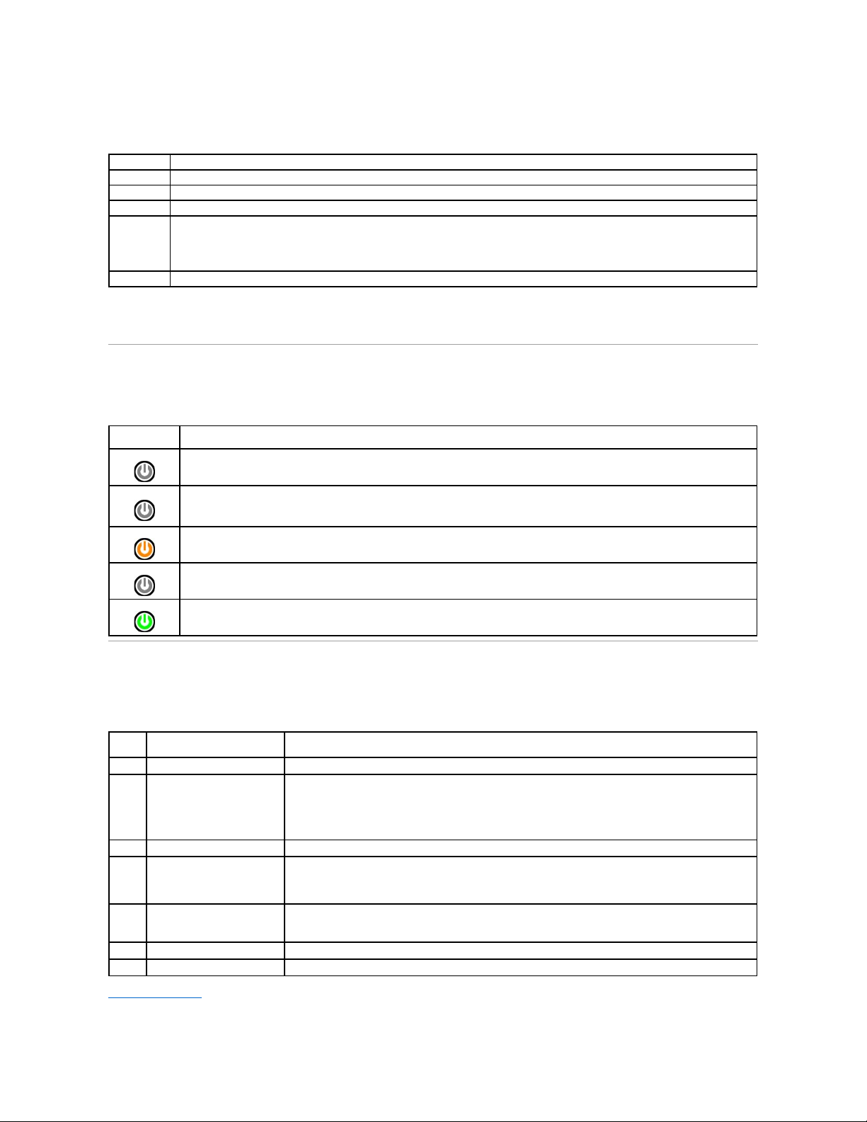
Power Button Light Codes
The diagnostic lights give much more information about the system state, but legacy power light states are also supported in your computer. The power light
states are shown in following table.
Beep Codes
If the monitor cannot display error messages during the POST, the computer may emit a series of beeps that identifies the problem or that can help you
identify a faulty component or assembly. The following table lists the beep codes that may be generated during the POST. Most beep codes indicate a fatal
error that prevents the computer from completing the boot routine until the indicated condition is corrected.
Back to Contents Page
Tab
Function
Results
Displays the results of the test and any error conditions encountered.
Errors
Displays error conditions encountered, error codes, and the problem description.
Help
Describes the test and may indicate requirements for running the test.
Configuration
Displays your hardware configuration for the selected device.
The Dell Diagnostics obtains configuration information for all devices from system setup, memory, and various internal tests, and it displays
the information in the device list in the left pane of the screen. The device list may not display the names of all the components installed on
your computer or all devices attached to your computer.
Parameters
Allows you to customize the test by changing the test settings.
Power Light
State
Description
Off
Power is off, light is blank.
Blinking Amber
Initial state of light at power up.
Indicates system has power, but the POWER_GOOD signal is not yet active.
If the Hard Drive light is off, it is probable that the power supply needs to be replaced.
If the Hard Drive light on, it is probable that an onboard regulator or VRM has failed. Look at the diagnostic lights for further information.
Solid Amber
Second state of the light at power up. Indicates the POWER_GOOD signal is active and it is probable that the power supply is fine. Look at
the diagnostic lights for further information.
Blinking Green
System is in a low power state, either S1 or S3. Look at the diagnostic lights to determine which state the system is in.
Solid Green
System is in S0 state, the normal power state of a functioning machine.
The BIOS will turn the light to this state to indicate it has started fetching opcodes.
Beep
Code
Description
Possible Solution
1
BIOS checksum failure.
Possible system board failure. Contact Dell.
2
No memory modules are
detected
1. If you have two or more memory modules installed, remove the modules, reinstall one module, and then
restart the computer. If the computer starts normally, reinstall an additional module. Continue until you
have identified a faulty module or reinstalled all modules without error.
2. If available, install good memory of the same type into your computer.
3. If the problem persists, contact Dell.
3
Possible system board failure
Contact Dell.
4
RAM Read/Write failure
1. Ensure that no special memory module/memory connector placement requirements exist.
2. Verify that the memory modules that you are installing are compatible with your computer.
3. If the problem persists, contact Dell.
5
Real-time clock failure. Possible
battery failure or system board
failure.
1. Replace the battery.
2. If the problem persists, contact Dell.
6
Video BIOS Test Failure
Contact Dell.
7
CPU-cache test failure
Contact Dell.
Page 7

Page 8

Back to Contents Page
Removing and Replacing Parts
Dell™Vostro™430ServiceManual
Back to Contents Page
Cover
Power-Button Assembly
Expansion Cards
Hard Drive
Chassis Fan
Processor
Coin-Cell Battery
Front Panel
Front I/O Panel
Memory
Optical Drive
Processor Heat Sink and Fan Assembly
Power Supply
System Board
Page 9
Back to Contents Page
Passwords
Dell™Vostro™430ServiceManual
Your computer provides the following password features in System Setup to help secure your computer:
l Supervisor Password
l User Password
Supervisor Password
The supervisor password is a systems level password that controls access to the system setup program.
Assigning a Supervisor Password
1. Enter System Setup.
2. Select Set Supervisor Password and press <Enter>.
3. Enter a password and press <Enter>.
4. To confirm the password, enter the password again and press <Enter>.
User Password
The user password is for users who only need to boot to an operating system on the computer. After you assign a user password, the computer prompts you
for the user password during the boot process. If security is a concern, you should operate your computer with user password protection.
Assigning a User Password
1. Enter System Setup.
2. Assign a Supervisor Password.
3. Select Set User Password and press <Enter>.
4. Enter a password at the prompt and press <Enter>.
5. To confirm the password, enter the password again and press <Enter>.
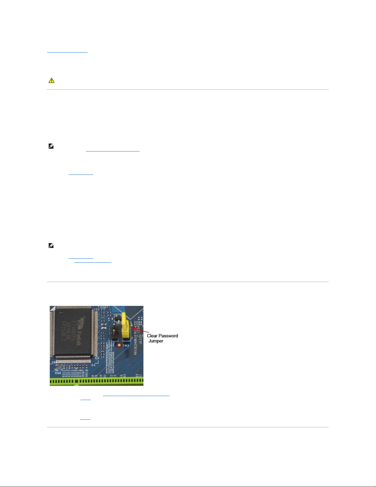
Clearing Forgotten Passwords
1. Follow the procedures in Before Working Inside Your Computer.
2. Remove the Cover.
3. Locate the 3-pin password connector (PSWD) on the system board.
4. Remove the 2-pin jumper plug from pins 2 and 3 and place it on pins 1 and 2.
5. Wait for approximately five seconds to clear the password.
6. Remove the 2-pin jumper plug from pins 1 and 2 and replace it on pins 2 and 3 to enable the password feature.
7. Replace the Cover.
WARNING: Before working inside your computer, read the safety information that shipped with your computer. For additional safety best
practices information, see the Regulatory Compliance Homepage at www.dell.com/regulatory_compliance.
NOTE: If you assign and forget the supervisor password the password can only be removed using the PSWD jumper on the system board. For more
information see, Clearing Forgotten Passwords.
NOTE: The user password is visible or accessible in System Setup only if a supervisor password has been set.
Page 10

Clearing CMOS Settings
1. Follow the procedures in Before Working Inside Your Computer.
2. Remove the Cover.
3. Locate the 3-pin CMOS jumper (CLEAR CMOS) on the system board.
4. Remove the jumper plug from the CMOS jumper (CLEAR CMOS) pins 2 and 3.
5. Place the jumper plug on the CMOS jumper (CLEAR CMOS) pins 1 and 2 and wait approximately five seconds.
6. Remove the jumper plug and replace it on the CMOS jumper (CLEAR CMOS) pins 2 and 3.
7. Replace the Cover.
Back to Contents Page
Page 11
Back to Contents Page
Technical Specifications
Processor
Drives
Memory
External Connectors
Video
Systemboard Connectors
Audio
Controls and Lights
Network
Power
System Information
Physical
Expansion Bus
Environmental
Cards
NOTE: Offerings may vary by region. For more information regarding the configuration of your computer, click Start® Help and Support and select the
option to view information about your computer.
Processor
Type
Intel® Core™i3/i5/i7series
Level 3 (L3) cache
8 MB
Memory
Type
DDR3 SDRAM (non-ECC memory only)
Speed
1066 MHz, 1333 MHz
Connectors
four
Capacity
1 GB, 2 GB, or 4 GB
Minimum memory
1 GB
Maximum memory
16 GB
Video
Discrete
PCI Express x16 graphics card:
l ATIRadeon™HD4350— 512 MB DDR2
l NVIDIA GT310 — 512 MB DDR2
l NVIDIA GT 220 — 1024 MB DDR3
l NVIDIA GTS 240 — 1024MB DDR3
Integrated
integrated on Intel Core i3/i5 series processors
(Intel H57 Express Chipset only)
NOTE: Intel Core i5-750/750S,
Intel Core i7
860/860S/870/880/920/940/950/965/975 processor
types do NOT support integrated video.
Memory
512 MB, 1024 MB
Audio
Integrated
5.1 channel High Definition audio
Discrete
Creative PCI Express Sound Blaster X-Fi Xtreme
Network
Integrated
Broadcom integrated network interface card capable
of 10/100/1000 mb/s communication
System Information
Chipset
Intel P55 Express Chipset
DMA channels
eight
Interrupt levels
24
BIOS chip (NVRAM)
16 Mb (2 MB)
Expansion Bus
Bus type
PCI 2.3
PCI Express 2.0
SATA 1.0A and 2.0
USB 2.0
Page 12
Bus speed
PCI: 133 MB/s
PCI Express:
l x1-slot bidirectional speed — 500 MB/s
l x16-slot bidirectional speed — 8 GB/s
SATA: 1.5 Gb/s and 3.0 Gb/s
USB: 480 Mb/s
Cards
PCI
two full height cards
PCI Express x1
one full height card
PCI Express x16
one full height card
Drives
Externally accessible:
5.25-inch drive bays
two bays for SATA DVD-ROM / DVD+/–RW / CDRW /
Blu-RayDisc™drive
3.5-inch drive bay
19-in-1 Media Card reader
Internally accessible:
3.5-inch drive bays
two bays for hard drives
External Connectors
Audio: back panel
three connectors for line-in, line-out, and microphone
front panel
two connectors for microphone and headphone
Network adapter
one RJ45 connector
Serial
one 9-pin connector; 16550C compatible
USB: front panel
four
back panel
six
Video
15-pin VGA connector
28-pin DVI-I connector
19-pin HDMI connector
4-pin S-Video connector
NOTE: Available video connectors may vary based on
the graphics card selected.
Systemboard Connectors
PCI 2.3: connectors
two 120-pin connectors
data width (maximum)
32 bits
PCI Express x1:
connectors
one 36-pin connector
data width (maximum)
one PCI-Express lane
PCI Express x16:
connectors
one 164-pin connector
data width (maximum)
16 PCI-Express lanes
Serial ATA
four 7-pin connectors
Memory
four 240-pin connectors
Internal USB device
one 10-pin connector (supports two USB ports)
Processor fan
one 4-pin connector
System fan
one 3-pin connector
Front panel control
one 9-pin connector
Front panel audio
one 10-pin connector
SPDIF audio
one 6-pin connector
Processor
one LGA1156 connector
Power 12V
one 4-pin connector
Power
one 24-pin connector
Page 13
Controls and Lights
Front of the computer:
Power button
push button
Power light
off — system is either turned off or is not receiving
power
blue — system is fully functional and in the On state.
Blinking blue indicates sleep state of the computer.
amber — solid amber light when the computer does
not start indicates a problem with the system board
or power supply.
Blinking amber light indicates a problem with one of
the devices in the system.
Drive access light
displays the SATA hard drive or CD/DVD activity.
blue light — blinking blue light indicates that the
computer is reading data from or writing data to the
drive(s).
Back of the computer:
Link integrity light on integrated network
adapter
off — system is off or is not detecting a physical
connection to the network.
green — A 10 or 100 mb/s connection exists between
the network and the computer.
orange — A 1000 mb/s connection exists between
the network and the computer.
Network activity light on integrated network
adapter
yellow light — A blinking yellow light indicates that
network activity is present.
Power supply diagnostic light
green — A green light indicates that the 5 V standby
power is OK.
Power
DC power supply:
Wattage
350 W non-EPA
Maximum heat dissipation (MHD)
1837 BTU/hr
Voltage
100–127 V/200–240 V, 50–60 Hz, 10/5 A
Coin-cell battery
3 V CR2032 lithium coin cell
NOTE: Heat dissipation is calculated by using the power supply wattage rating.
NOTE: See the safety information that shipped with your computer for important voltage setting information.
Physical
Height
370.40 mm (14.58 inches)
Width
170.00 mm (6.69 inches)
Depth
442.75 mm (17.43 inches)
Weight
8.1 kg–10.65 kg (17.86 lb–23.48 lb)
Environmental
Temperature:
Operating
10°Cto35°C(50°Fto95°F)
Storage
–40°Cto65°C(–40°Fto149°F)
Relative humidity (noncondensing)
operating: 20% to 80%
(maximumwetbulbtemperature:29°C)
storage: 5% to 95%
(maximumwetbulbtemperature:38°C)
Maximum vibration:
Operating
5 Hz–350 Hz at 0.0002 G2/Hz
Storage
5 Hz–500 Hz at 0.001 to 0.01 G2/Hz
Maximum shock:
Operating
40 G +/– 5% with pulse duration of 2 msec +/– 10%
(equivalent to 20 in/sec [51 cm/sec])
Storage
105 G +/– 5% with pulse duration of 2 msec +/– 10%
(equivalent to 50 in/sec [127 cm/sec])
Altitude:
Page 14

Back to Contents Page
Operating
–15.2 m to 3048 m (–50 ft to 10,000 ft)
Storage
–15.2 m to 10,668 m (–50 ft to 35,000 ft)
Airborne contaminant level
G2 or lower as defined by ISA-S71.04-1985
Page 15
Back to Contents Page
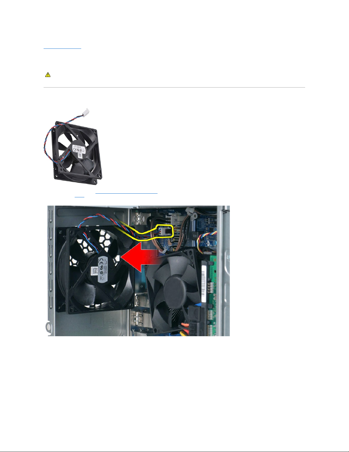
Chassis Fan
Dell™Vostro™430ServiceManual
Removing the Chassis Fan
1. Follow the procedures in Before Working Inside Your Computer.
2. Remove the Cover.
3. Disconnect the fan cable from the system board.
4. While holding the chassis fan in place, remove the two screws that secure the fan to the chassis.
WARNING: Before working inside your computer, read the safety information that shipped with your computer. For additional safety best
practices information, see the Regulatory Compliance Homepage at www.dell.com/regulatory_compliance.
Page 16

5. Ease the fan towards the center of the computer, and lift the fan out of the chassis.
Replacing the Chassis Fan
To replace the chassis fan, perform the above step in reverse order.
Back to Contents Page
Page 17

Back to Contents Page
Coin-Cell Battery
Dell™Vostro™430ServiceManual
Removing the Coin-Cell Battery
1. Follow the procedures in Before Working Inside Your Computer.
2. Remove the Cover.
3. Gently press the release latch away from the battery.
4. Lift the coin-cell battery out of the computer.
WARNING: Before working inside your computer, read the safety information that shipped with your computer. For additional safety best
practices information, see the Regulatory Compliance Homepage at www.dell.com/regulatory_compliance.
Page 18

Replacing the Coin-Cell Battery
To replace the coin-cell battery, perform the above steps in reverse order.
Back to Contents Page
Page 19

Back to Contents Page
Front Panel
Dell™Vostro™430ServiceManual
Removing the Front Panel
1. Follow the procedures in Before Working Inside Your Computer.
2. Remove the Cover.
3. Gently lift the clips that secure the front panel to the chassis.
4. Rotate the front panel away from the computer.
WARNING: Before working inside your computer, read the safety information that shipped with your computer. For additional safety best
practices information, see the Regulatory Compliance Homepage at www.dell.com/regulatory_compliance.
Page 20

Replacing the Front Panel
To replace the front panel, perform the above steps in reverse order.
Back to Contents Page
Page 21

Back to Contents Page
Front I/O Panel
Dell™Vostro™430ServiceManual
Removing the Front I/O Panel
1. Follow the procedures in Before Working Inside Your Computer.
2. Remove the Cover.
3. Remove the Front Panel.
4. Disconnect the three front I/O cables from the system board.
5. Remove the cables from the guides along the inside of the chassis.
6. Using a Phillips head screwdriver, remove the screw that secures the front I/O panel to the chassis.
WARNING: Before working inside your computer, read the safety information that shipped with your computer. For additional safety best
practices information, see the Regulatory Compliance Homepage at www.dell.com/regulatory_compliance.
Page 22

7. Move the front I/O panel away from the computer as you guide the cables through the cable guides on the chassis.
Replacing the Front I/O Panel
To replace the front I/O panel, perform the above steps in reverse order.
Back to Contents Page
CAUTION: Remove the cables carefully from the cable guides and cable routing clip(s) to prevent damaging the cables and cable routing clip(s).
Page 23

Back to Contents Page
Hard Drive
Dell™Vostro™430ServiceManual
Removing the Hard Drive
1. Follow the procedures in Before Working Inside Your Computer.
2. Remove the Cover.
3. Disconnect the data cable from the back of the hard drive.
4. Disconnect the power cable from the back of the hard drive.
WARNING: Before working inside your computer, read the safety information that shipped with your computer. For additional safety best
practices information, see the Regulatory Compliance Homepage at www.dell.com/regulatory_compliance.
Page 24

5. Using a Phillips head screwdriver, remove the four screws that secure the hard drive to the drive cage.
6. Slide the hard drive towards the back of the computer to remove the hard drive from the hard-drive bay.
Page 25

Replacing the Hard Drive
To replace the hard drive, perform the above steps in reverse order.
Back to Contents Page
Page 26

Back to Contents Page
Processor Heat Sink and Fan Assembly
Dell™Vostro™430ServiceManual
Removing the Processor Heat Sink and Fan Assembly
1. Follow the procedures in Before Working Inside Your Computer.
2. Remove the Cover.
3. Disconnect the processor heat sink and fan assembly cable from the system board.
4. Using a Phillips head screwdriver, loosen the four captive screws that secure the processor heat sink and fan assembly to the system board.
WARNING: Before working inside your computer, read the safety information that shipped with your computer. For additional safety best
practices information, see the Regulatory Compliance Homepage at www.dell.com/regulatory_compliance.
Page 27

5. Lift the heat-sink and fan assembly from the computer, then place the assembly aside with the thermal grease facing upward.
Replacing the Processor Heat Sink and Fan Assembly
To replace the processor heat sink and fan assembly, perform the above steps in reverse order.
Back to Contents Page
Page 28

Back to Contents Page
Memory
Dell™Vostro™430ServiceManual
Removing Memory
1. Follow the procedures in Before Working Inside Your Computer.
2. Remove the Cover.
3. Press the securing clips at each end of the memory module connector.
4. Grasp the module and pull it upwards.
WARNING: Before working inside your computer, read the safety information that shipped with your computer. For additional safety best
practices information, see the Regulatory Compliance Homepage at www.dell.com/regulatory_compliance.
Page 29

Replacing Memory
1. Follow the procedures in Before Working Inside Your Computer.
2. Remove the Cover.
3. Press out the securing clip on each end of the memory module connector.
4. Align the notch at the bottom of the module with the crossbar in the connector.
5. Insert the module in the connector until the module snaps into place.
6. Replace the Cover.
Back to Contents Page
CAUTION: To avoid electrostatic discharge and damage to internal components, ground yourself by using a wrist grounding strap or by
periodically touching an unpainted metal surface on the computer chassis before you install the memory module.
Page 30

Back to Contents Page
Optical Drive
Dell™Vostro™430ServiceManual
Removing the Optical Drive
1. Follow the procedures in Before Working Inside Your Computer.
2. Remove the Cover.
3. Remove the Front Panel.
4. Disconnect the data cable from the back of the optical drive.
5. Disconnect the power cable from the back of the optical drive.
WARNING: Before working inside your computer, read the safety information that shipped with your computer. For additional safety best
practices information, see the Regulatory Compliance Homepage at www.dell.com/regulatory_compliance.
Page 31

6. Using a Phillips head screwdriver, remove the two screws that secure the optical drive to the drive cage.
7. Slide the optical drive out from the front of the computer.
Replacing the Optical Drive
To replace the optical drive, perform the above steps in reverse order.
Back to Contents Page
Page 32

Back to Contents Page
Power-Button Assembly
Dell™Vostro™430ServiceManual
Removing the Power-Button Assembly
1. Follow the procedures in Before Working Inside Your Computer.
2. Remove the Cover.
3. Remove the Front Panel.
4. Disconnect the power-button cable from the system board.
5. Press down on the clips that secure the hard-drive activity light and power-button assembly to the front panel.
6. Pull the hard-drive activity light and power-button assembly away from the computer.
WARNING: Before working inside your computer, read the safety information that shipped with your computer. For additional safety best
practices information, see the Regulatory Compliance Homepage at www.dell.com/regulatory_compliance.
Page 33

Replacing the Power-Button Assembly
To replace the power-button assembly, perform the above steps in reverse order.
Back to Contents Page
Page 34

Back to Contents Page
Power Supply
Dell™Vostro™430ServiceManual
Removing the Power Supply
1. Follow the procedures in Before Working Inside Your Computer.
2. Remove the Cover.
3. Disconnect power cables from all the internal devices including the system board, hard drives, and optical drives.
4. Remove the cables from the routing clips (if any) on the chassis.
WARNING: Before working inside your computer, read the safety information that shipped with your computer. For additional safety best
practices information, see the Regulatory Compliance Homepage at www.dell.com/regulatory_compliance.
Page 35

5. Remove the four screws that secure the power supply to the back of the chassis.
6. Push the release tab beside the power supply and slide the power supply towards the front of the computer.
Page 36

7. Lift the power supply out of the computer.
Replacing the Power Supply
To replace the power supply, perform the above steps in reverse order.
Back to Contents Page
Page 37

Back to Contents Page
Processor
Dell™Vostro™430ServiceManual
Removing the Processor
1. Follow the procedures in Before Working Inside Your Computer.
2. Remove the Cover.
3. Remove the Processor Heat-Sink and Fan Assembly.
4. Push the release lever down and out of its retention hook.
5. Lift the release lever and open the processor cover.
WARNING: Before working inside your computer, read the safety information that shipped with your computer. For additional safety best
practices information, see the Regulatory Compliance Homepage at www.dell.com/regulatory_compliance.
Page 38

6. Remove the processor from the socket.
Leave the release lever extended in the release position so that the socket is ready for the processor to be replaced.
Replacing the Processor
1. Align the pin-1 corner of the processor and socket.
CAUTION: To avoid electrostatic discharge and damage to internal components, ground yourself by using a wrist grounding strap or by
periodically touching an unpainted metal surface on the computer chassis before you install the processor.
Page 39

2. Set the processor lightly in the socket and ensure that the processor is aligned in the socket. When the processor is positioned correctly, apply minimal
pressure to seat it.
3. When the processor is fully seated in the socket, close the processor cover.
4. Pivot the socket release lever back toward the socket and snap it into place to secure the processor.
5. Replace the processor Heat-Sink and Fan Assembly.
6. Replace the Cover.
Back to Contents Page
Page 40

Back to Contents Page
System Board
Dell™Vostro™430ServiceManual
Removing the System Board
1. Follow the procedures in Before Working Inside Your Computer.
2. Remove the Cover.
3. Remove the Memory.
4. Remove the Processor Heat-Sink and Fan Assembly.
5. Remove the Processor.
6. Remove the Expansion Cards.
7. Disconnect the cables from all the internal devices including the system board, hard-drive(s), optical-drive(s), and expansion cards.
8. Using a Phillips head screwdriver, remove the nine screws that secure the system board to the computer chassis.
9. Slide the system board towards the front of the computer.
WARNING: Before working inside your computer, read the safety information that shipped with your computer. For additional safety best
practices information, see the Regulatory Compliance Homepage at www.dell.com/regulatory_compliance.
Page 41

10. Tilt and lift the system board out of the computer chassis.
11. Place the system board into antistatic packaging.
Replacing the System Board
To replace the system board, perform the above steps in reverse order.
Back to Contents Page
WARNING: When replacing the system board, slide the system board below the metal tabs. Pressing down on the system board (when
placed above the metal tabs) can damage the system board.
Page 42

Back to Contents Page
Cover
Dell™Vostro™430ServiceManual
Removing the Cover
1. Follow the procedures in Before Working Inside Your Computer.
2. Remove the two thumbscrews that secure the cover to the computer.
3. Slide the cover towards the back of the computer.
WARNING: Before working inside your computer, read the safety information that shipped with your computer. For additional safety best
practices information, see the Regulatory Compliance Homepage at www.dell.com/regulatory_compliance.
Page 43

4. Lift the cover away from the computer.
Replacing the Cover
To replace the computer cover, perform the above steps in reverse order.
Back to Contents Page
Page 44

Back to Contents Page
Expansion Cards
Dell™Vostro™430ServiceManual
Removing an Expansion Card
1. Follow the procedures in Before Working Inside Your Computer.
2. Remove the Cover.
3. Disconnect any cables that may be connected to the card.
4. Using a Phillips head screwdriver, remove the screw and metal tab that secure the expansion card to the chassis.
5. To remove a PCI-Express x16 video card, press the securing tab on the system board connector as you grasp the card by its top corners, and then ease
the card out of the connector.
WARNING: Before working inside your computer, read the safety information that shipped with your computer. For additional safety best
practices information, see the Regulatory Compliance Homepage at www.dell.com/regulatory_compliance.
Page 45

6. To remove a PCI-Express X1 or PCI card, grasp the card by its top corners, and then ease the card out of the connector.
Replacing an Expansion Card
To replace an expansion card, perform the above steps in reverse order.
Back to Contents Page
Page 46

Back to Contents Page
System-Board Layout
Dell™Vostro™430ServiceManual
Back to Contents Page
1
front I/O panel connector
2
SPDIFoutconnector
3
USB2 connector (from front I/O panel)
4
USB1 connector (from front I/O panel)
5
USB3 system-board connector
6
Clear CMOS jumper
7
PCI connector (PCI1)
8
PCI connector (PCI2)
9
front audio connector
10
CMOS battery
11
PCI Express x1 connector (PCIE_x1)
12
PCI Express x16 connector (PCIE_x16)
13
audio connector
14
network connector and USB connectors (2)
15
USB connectors (4)
16
serial connector
17
PS/2 mouse and keyboard connectors
18
power connector (PWR2)
19
Clear Password jumper
20
processor socket
21
processor-fan power connector
22
memory slot (DIMM1)
23
memory slot (DIMM2)
24
memory slot (DIMM3)
25
memory slot (DIMM4)
26
main power connector (PWR1)
27
NVRAM slot
28
serial ATA hard drive connector
(SATA1,SATA2,SATA3, and SATA4)
Page 47

Back to Contents Page
Working on Your Computer
Dell™Vostro™430ServiceManual
Before Working Inside Your Computer
Use the following safety guidelines to help protect your computer from potential damage and to help to ensure your personal safety. Unless otherwise noted,
each procedure included in this document assumes that the following conditions exist:
l You have performed the steps in Working on Your Computer.
l You have read the safety information that shipped with your computer.
l A component can be replaced or--if purchased separately--installed by performing the removal procedure in reverse order.
To avoid damaging your computer, perform the following steps before you begin working inside the computer.
1. Ensure that your work surface is flat and clean to prevent the computer cover from being scratched.
2. Turn off your computer (see Turning Off Your Computer).
3. Disconnect all network cables from the computer.
4. Disconnect your computer and all attached devices from their electrical outlets.
5. Press and hold the power button while the system is unplugged to ground the system board.
6. Remove the computer cover (see Removing and Replacing the Cover).
Recommended Tools
The procedures in this document may require the following tools:
l Small flat-blade screwdriver
l Phillips screwdriver
l Small plastic scribe
l Flash BIOS update program media
Turning Off Your Computer
1. Shut down the operating system:
l In Windows Vista®:
Click Start , then click the arrow in the lower-right corner of the Start menu as shown below, and then click Shut Down.
l In Windows®XP:
Before Working Inside Your Computer
Recommended Tools
Turning Off Your Computer
After Working Inside Your Computer
WARNING: Before working inside your computer, read the safety information that shipped with your computer. For additional safety best
practices information, see the Regulatory Compliance Homepage at www.dell.com/regulatory_compliance.
CAUTION: Only a certified service technician should perform repairs on your computer. Damage due to servicing that is not authorized by Dell is
not covered by your warranty.
CAUTION: To avoid electrostatic discharge, ground yourself by using a wrist grounding strap or by periodically touching an unpainted metal
surface, such as a connector on the back of the computer.
CAUTION: Handle components and cards with care. Do not touch the components or contacts on a card. Hold a card by its edges or by its metal
mounting bracket. Hold a component such as a processor by its edges, not by its pins.
CAUTION: When you disconnect a cable, pull on its connector or on its pull-tab, not on the cable itself. Some cables have connectors with locking
tabs; if you are disconnecting this type of cable, press in on the locking tabs before you disconnect the cable. As you pull connectors apart, keep
them evenly aligned to avoid bending any connector pins. Also, before you connect a cable, ensure that both connectors are correctly oriented
and aligned.
NOTE: The color of your computer and certain components may appear differently than shown in this document.
CAUTION: To disconnect a network cable, first unplug the cable from your computer and then unplug the cable from the network device.
CAUTION: Before touching anything inside your computer, ground yourself by touching an unpainted metal surface, such as the metal at the back
of the computer. While you work, periodically touch an unpainted metal surface to dissipate static electricity, which could harm internal
components.
CAUTION: To avoid losing data, save and close all open files and exit all open programs before you turn off your computer.
Page 48

Click Start® Turn Off Computer® Turn Off.
The computer turns off after the operating system shutdown process is complete.
2. Ensure that the computer and all attached devices are turned off. If your computer and attached devices did not automatically turn off when you shut
down your operating system, press and hold the power button for about 6 seconds to turn them off.
After Working Inside Your Computer
After you complete any replacement procedure, ensure you connect any external devices, cards, and cables before turning on your computer.
1. Replace the cover (see Removing and Replacing the Cover).
2. Connect any telephone or network cables to your computer.
3. Connect your computer and all attached devices to their electrical outlets.
4. Turn on your computer.
5. Verify that the computer works correctly by running the Dell Diagnostics. See Dell Diagnostics.
Back to Contents Page
CAUTION: To connect a network cable, first plug the cable into the network device and then plug it into the computer.
 Loading...