

Page 1
®
Page 2

®
Page 3

Information in this document is subject to change without notice.
1995–1996 Dell Computer Corporation. All rights reserved.
Reproduction in any manner whatsoever without the written permission of Dell Computer Corporation is strictly forbidden.
Trademarks used in this text: Dell, the DELL logo, and PowerEdge are registered trademarks, DellWare is a registered service mark, and Dell
Dimension is a trademark of Dell Co mputer Corporation; Pentium is a registered trademark of Intel Corporatio n; Microsoft, Windows, and MS-DOS
are registered trademarks of Microsoft Corporation; CompuServe is a registered trademark of CompuServe, Inc.; and PRODIGY is a registered
trademark of Prodigy Services Co.
Other trademarks and trade names may be used in this document to refer to either the entities claiming the marks and names or their products.
Dell Computer Corporation disclaims any proprietary interest in trademarks and trade names other than its own.
October 1996 P/N 40721
Page 4

Safety Instructions
U
se the following safety guidelines to help protect
your computer system from potential damage and to
ensure your own personal safety.
W
hen Working Inside the
Computer
WARNING: The power supplies in this computer
system produce high voltages and energy hazards,
which can cause bodily harm. Only trained service
technicians are authorized to remove the computer
covers and access any of the components inside the
computer.
Before taking the covers off of the computer, perform the
following steps in the sequence indicated:
1. Turn off the computer and any peripherals.
2. Disconnect the computer and peripherals from
their power sources. Also, disconnect any telephone or telecommunications lines from the
computer.
Doing so reduces the potential for personal injury or
shock.
3. Touch an unpainted metal surface on the com-
puter chassis, such as the power supply, before
touching anything inside the computer.
While you work, periodically touch an unpainted
metal surface on the computer chassis to dissipate
any static electricity that might harm internal
components.
In addition, take note of these safety guidelines when
appropriate:
•
To help avoid possible damage to the system board,
wait five seconds after turning off the system before
removing a component from the system board or disconnecting a peripheral device from the computer.
•
When you disconnect a cable, pull on its connector
or on its strain-relief loop, not on the cable itself.
Some cables have a connector with locking tabs; if
you are disconnecting this type of cable, press in on
the locking tabs before disconnecting the cable. As
you pull connectors apart, keep them evenly aligned
to avoid bending any connector pins. Also, before
you connect a cable, make sure both connectors are
correctly oriented and aligned.
•
Handle components and cards with care. Don’t touch
the components or contacts on a card. Hold a card by
its edges or by its metal mounting bracket. Hold a
component such as a microprocessor chip by its
edges, not by its pins.
Protecting Against Electrostatic
Discharge
Static electricity can harm delicate components inside the
computer. To prevent static damage, discharge static electricity from your body before you touch any of the
computer’s electronic components, such as the microprocessor. You can do so by touching an unpainted metal
surface on the computer chassis.
As you continue to work inside the computer, periodically touch an unpainted metal surface to remove any
static charge your body may have accumulated.
v
Page 5

In addition to the preceding precautions, you can also
take the following steps to prevent damage from electrostatic discharge (ESD):
•
When unpacking a static-sensitive component from
its shipping carton, do not remove the component’s
antistatic packing material until you are ready to
install the component in the computer. Just before
unwrapping the antistatic packaging, be sure to discharge static electricity from your body.
•
When transporting a sensitive component, first place
it in an antistatic container or packaging.
•
Handle all sensitive components in a static-safe area.
If possible, use antistatic floor pads and workbench
pads.
The following caution appears throughout this document
to remind you of these precautions:
CAUTION: See “Protecting Against Electrostatic
Discharge” in the safety instructions at the front of
this guide.
W
hen Using the Computer
System
•
To help prevent electric shock, plug the computer
and peripheral power cables into properly grounded
power sources. These cables are equipped with
three-prong plugs to ensure proper grounding. Do
not use adapter plugs or remove the grounding prong
from a cable. If you must use an extension cable, use
a three-wire cable with properly grounded plugs.
•
To help protect the computer system from sudden,
transient increases and decreases in electrical power,
use a surge suppressor, line conditioner, or uninterruptible power supply.
•
Be sure nothing rests on the computer system’s
cables and that the cables are not located where they
can be stepped on or tripped over.
•
Do not spill food or liquids on the computer. If the
computer gets wet, see Chapter 7, “Checking Inside
the Computer.”
•
Do not push any objects into the openings of the
computer. Doing so can cause fire or electric shock
by shorting out interior components.
•
Keep the computer away from radiators and heat
sources. Also, do not block cooling vents. Avoid
placing loose papers underneath the computer; do
not place the computer in a closed-in wall unit or on
a rug.
As you use the computer system, observe the following
safety guidelines:
•
Be sure the monitor and attached peripherals are
electrically rated to operate with the AC power available in your location.
vi
Page 6

Preface
A
bout This Guide
This guide provides directions for trained service technicians who are installing system upgrade options in a Dell
PowerEdge 4100/180 or Dell PowerEdge 4100/200 computer system or are troubleshooting problems that have
temporarily disabled a system. Before calling for technical assistance, follow the recommended procedure(s) in
this guide to solve most hardware and software problems
yourself.
•
Chapter 1, “Introduction,” provides a brief overview
of system service features.
•
Everyone should read Chapter 2, “Checking the
Basics,” for some initial checks and procedures that
can be used to solve basic computer problems. It also
directs you to the appropriate chapter in this guide
for more detailed troubleshooting information and
procedures to solve more complex problems.
•
Whenever you receive an error message or code, you
should read Chapter 3, “Messages and Codes.” This
chapter discusses system messages, system beep
codes, warning messages, and diagnostics messages.
•
If you suspect that the problems are software-related,
or you are still having problems after testing the
computer’s hardware, read Chapter 4, “Finding Software Solutions.” It provides some general guidelines
for analyzing software problems.
•
For hardware-related problems, read Chapter 5,
“Running the System Diagnostics.” Chapter 6,
“Checking the Equipment,” and Chapter 7, “Checking Inside the Computer,” provide troubleshooting
procedures for equipment connected to the input/
output (I/O) panel of the computer and components
inside the computer, respectively. Chapter 7 also provides information on removing the computer covers.
•
Chapter 8, “Installing System Board Options,”
Chapter 9, “Installing Drives in the External Bays,”
and Chapter 10, “Installing Drives in the Internal
Bays,” are intended for technicians who want to
install or remove options inside the computer, such
as dual in-line memory modules (DIMMs), expansion cards, or SCSI devices.
•
Chapter 11, “Getting Help,” describes the help tools
Dell provides to assist you should you have a problem with the computer. It also explains how and
when to call Dell for technical assistance.
•
Make a copy of the checklist in Appendix A, “Diagnostics Checklist,” and fill it out as you perform the
troubleshooting procedures. If you need to call Dell
for technical assistance, use the completed checklist
to tell the support technician what procedures you
performed to better help the Dell technician give you
assistance. If you must return a piece of hardware to
Dell, include a filled-out checklist.
•
Appendix B, “Diagnostic Video Tests,” discusses the
tests for the Video Test Group in the system diagnostics to help you test the monitor.
•
Appendix C, “Jumpers and Switches,” is intended
for technicians who are troubleshooting the system
or adding internal options and need to change jumper
or switch settings.
•
A table of the abbreviations and acronyms used
throughout this guide and in other Dell documentation for the system precedes the index.
vii
Page 7

O
ther Documentation You May
Need
You may need to reference the following documentation
when performing the procedures in this guide:
•
The Dell PowerEdge 4100/180 and 4100/200 Systems User’s Guide, which describes system features
and technical specifications, video and small computer system interface (SCSI) device drivers, the
System Setup program, software support utilities,
and the EISA Configuration Utility.
•
The Dell PowerEdge 4100 Systems Rack Installation
Guide, which provides detailed instructions for
installing the system in a rack.
•
The Dell Hardware Instrumentation Package for
Intel LANDesk Server Manager User’s Guide, which
describes the alert messages issued by this server
management software.
You may also have one or more of the following
documents:
•
Operating system documentation is included with
the system if you ordered the operating system software from Dell. This documentation describes how
to install (if necessary), configure, and use the operating system software.
•
Documentation is included with any options you
purchase separately from the system, such as the
Dell PowerEdge Expandable RAID Controller SCSI
host adapter. This documentation includes information that you need to configure and install these
options in the Dell computer. Installation instructions for the options are included in the system
documentation.
•
Technical information files—sometimes called
“readme” files—may be installed on the hard-disk
drive to provide last-minute updates about technical
changes to the system or advanced technical reference material intended for experienced users or
technicians.
NOTE: Documentation updates are sometimes included
with the system to describe changes to the system or software. Always read these updates before consulting any
other documentation because the updates often contain information that supersedes the information in the other
documents.
N
otational Conventions
The following subsections list notational conventions
used in this document.
Warnings, Cautions, and Notes
Throughout this guide, there may be blocks of text
printed in bold type within boxes or in italic type. These
blocks are warnings, cautions, and notes, and they are
used as follows:
WARNING: A WARNING indicates the potential
for bodily harm and tells you how to avoid the
problem.
CAUTION: A CAUTION indicates either potential damage to hardware or loss of data and tells
you how to avoid the problem.
NOTE: A NOTE indicates important information that
helps you make better use of the computer system.
Typographical Conventions
The following list defines (where appropriate) and illustrates typographical conventions used as visual cues for
specific elements of text throughout this document:
•
Keycaps, the labeling that appears on the keys on a
keyboard, are presented in uppercase and enclosed in
angle brackets.
Example: <
•
Key combinations are series of keys to be pressed
simultaneously (unless otherwise indicated) to perform a single function.
Example: <
•
All items on a menu screen are presented in the
VETICA
font and in uppercase bold.
Example:
•
Commands presented in lowercase bold are for reference purposes only and are not intended to be typed
at that particular point in the discussion.
Example: “Use the format command to . . . .”
SETUP PASSWORD
>
ENTER
CTRL><ALT><ENTER
category
>
HEL-
viii
Page 8

In contrast, commands presented in the Courier
font are intended to be typed as part of an instruction.
Example: “Typ e format a: to format the diskette in
drive A.”
•
Filenames and directory names are presented in
lowercase bold.
Examples: autoexec.bat and c:\windows
•
Syntax lines consist of a command and all its
possible parameters. Commands are displayed in
lowercase bold; variable parameters (those for which
you substitute a value) are displayed in lowercase
italics; constant parameters are displayed in lowercase bold. The brackets indicate items that are
optional.
Example: del [drive:] [path]filename [/p]
•
Command lines consist of a command and may
include one or more of the command’s possible
parameters. Command lines are presented in
Courier.
Example:
del c:\myfile.doc
•
Screen text is text that appears on the screen of the
monitor or display. It can be a system message, for
example, or it can be text that you are instructed to
type as part of a command (referred to as a command
line). Screen text is presented in Courier font.
Example: “Type md c:\dos, and then press
<
>.”
ENTER
Example: The following message appears on the
screen:
No boot device available
•
Variables are symbols for which you substitute a
value. They are presented in italics.
Example: EISAn (where n represents the expansion-
card connector number)
ix
Page 9

x
Page 10

Chapter 1
Introduction
D
ell® PowerEdge™ 4100/180 and Dell PowerEdge 4100/200 systems are high-speed, upgradable
servers that offer a number of significant service and
upgrade features.
The Dell PowerEdge 4100 systems’ service features
make troubleshooting easy and effective. Every system
includes CD-based Dell diagnostics software for diagnosing system problems if the system can boot. The
embedded server management hardware monitors temperatures and voltages throughout the system and notifies
you if the system overheats or if one of the system cooling fans malfunctions. If the system has an optional
power-supply paralleling board and redundant power
supplies, the server management hardware also monitors
the status of the power supplies.
The Dell PowerEdge 4100 system chassis simplifies
removing and replacing computer components. Processor
and memory upgrades can be performed without removing the system board. The Dell-designed small computer
system interface (SCSI) backplane board and hard-disk
drive carriers eliminate the extensive cabling and drive
configuration usually required for a SCSI subsystem. The
plastic drive rails attached to devices mounted in the
external drive bays allow you to remove devices without
removing a single screw.
Among the many upgrade options offered for the Dell
PowerEdge 4100 systems are a secondary microprocessor, additional main memory, a variety of
expansion-card options (including the Dell PowerEdge
Expandable RAID Controller host adapter), and additional SCSI CD-ROM, tape, and hard-disk drives.
A
bout This Guide
This guide provides directions for trained service
technicians who are installing system options or are
troubleshooting problems that have temporarily disabled
a Dell PowerEdge system. Before calling for technical
assistance, follow the recommended procedure(s) in this
guide to solve most hardware and software problems
yourself.
•
Chapter 2, “Checking the Basics,” outlines some initial checks and procedures and also directs you to the
appropriate chapter in this guide for more detailed
troubleshooting information.
•
Whenever you receive an error message or code, you
should read Chapter 3, “Messages and Codes.”
•
If you suspect that the problems are software-related,
or you are still having problems after testing the
computer’s hardware, read Chapter 4, “Finding Software Solutions.”
•
For hardware-related problems, read Chapter 5,
“Running the System Diagnostics.” Chapter 6,
“Checking the Equipment,” and Chapter 7, “Checking Inside the Computer,” provide troubleshooting
procedures for equipment connected to the input/
output (I/O) panel of the computer and components
inside the computer, respectively.
Chapter 7 also provides information on removing the
computer covers and front bezel.
•
If you are installing or removing system options, such
as dual in-line memory modules (DIMMs), expansion
cards, or SCSI devices, refer to Chapter 8, “Installing
System Board Options,” Chapter 9, “Installing Drives
in the External Bays,” or Chapter 10, “Installing
Drives in the Internal Bays.”
Introduction 1-1
Page 11

•
Chapter 11, “Getting Help,” describes the help tools
Dell provides to assist you should you have a problem with the computer. It also explains how and
when to call Dell for technical assistance.
•
If you are performing troubleshooting procedures,
make a copy of Appendix A, “Diagnostics Checklist,” and fill it out. If you need to call Dell for
technical assistance, use the completed checklist to
tell the support technician what procedures you performed to better help the Dell technician give you
assistance. If you must return a piece of hardware to
Dell, include a filled-out copy of this checklist.
•
Appendix B, “Diagnostic Video Tests,” discusses the
tests for the Video Test Group in the system diagnostics to help you test the monitor.
•
Appendix C, “Jumpers and Switches,” is intended
for technicians who add internal options and need to
change jumper or switch settings.
•
A table of the abbreviations and acronyms used
throughout this guide and in other Dell documentation for the system precedes the index.
1-2 Dell PowerEdge 4100/180 and 4100/200 Systems Installation and Troubleshooting Guide
Page 12

Chapter 2
Checking the Basics
I
f a Dell PowerEdge 4100 computer system is not working as expected, start your troubleshooting with the
procedures in this chapter. This chapter guides you
through some initial checks and procedures that can solve
basic computer problems. It can also direct you to the
appropriate chapter in this guide for detailed troubleshooting information and procedures to solve more
complex problems.
NOTE: When you see the question, “Is the problem
resolved?” in a troubleshooting procedure, perform the
operation that caused the problem.
B
acking Up Files
If the system is behaving erratically, back up the files
immediately. See the documentation that came with the
operating system for instructions on how to back up the
files.
B
asic Checks
The following procedure leads you through the checks
necessary to solve some basic computer problems:
1. Was an alert message issued by the Dell HIP
server management program?
The Dell Hardware Instrumentation Package (HIP)
server management application program generates
warning and failure messages for drive, temperature,
fan, and power conditions. These messages appear in
the simple network management protocol (SNMP)
trap log file. To see the trap log, select any enterprise
under the SNMP trap log icon. (More information
about the Alert Log window and options is provided
in the Dell HIP online help.)
Ye s . Go to “Alert Log Messages From the Dell HIP
Program” in Chapter 3.
No. Go to step 2.
2. Is the computer wet or damaged?
Ye s . Go to Chapter 7, “Checking Inside the
Computer.”
No. Go to step 3.
3. Perform the steps in “Checking Connections and
Switches” found next in this chapter.
Is the problem resolved?
Ye s . The power to the computer system was faulty, or
the connections to the computer system were loose.
You have fixed the problem.
No. Go to step 4.
4. Perform the steps in “Look and Listen” found
later in this chapter.
Did the computer system complete the boot routine?
Ye s . Go to step 5.
No. A serious malfunction may have occurred. Go to
Chapter 11, “Getting Help.”
5. Did you receive a system message or beep code?
Ye s . Go to Chapter 3, “Messages and Codes.”
No. Go to step 6.
Checking the Basics 2-1
Page 13

6. Verify the settings in the System Setup program
as explained in “The System Setup Program”
found later in this chapter.
Is the problem resolved?
Ye s . The system configuration information was
incorrect. You have fixed the problem.
No. Go to step 7.
7. Run the system diagnostics as described in Chapter 5.
C
hecking Connections and
Switches
Improperly set switches and controls and loose or
improperly connected cables are the most likely source of
problems for the computer, monitor, or other peripherals
(such as a printer, keyboard, mouse, or other external
equipment). A quick check of all the switches, controls,
and cable connections can easily solve these problems.
Figure 2-1 shows the back panel connections on the computer. Figure 2-2 shows the switches and controls on the
computer.
2-2 Dell PowerEdge 4100/180 and 4100/200 Systems Installation and Troubleshooting Guide
Page 14
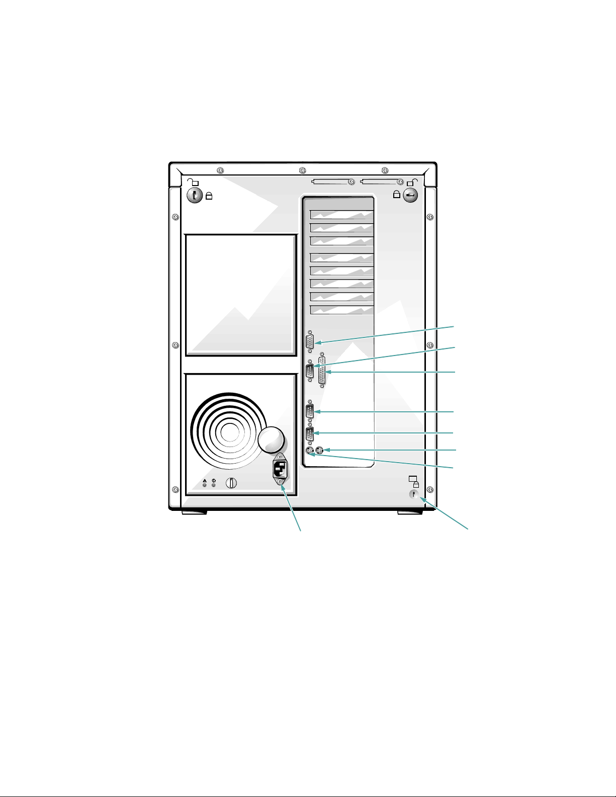
video connector
server-management
serial port
parallel port connector
serial port 2 connector
serial port 1 connector
mouse connector
keyboard connector
Figure 2-1. Back Panel Features
AC power receptacle
security cable slot
Checking the Basics 2-3
Page 15
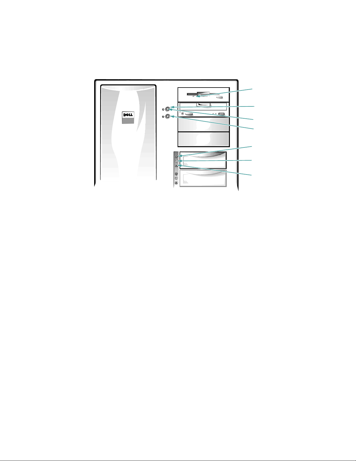
Figure 2-2. Switches and Controls
diskette-drive
access indicator
power switch
power indicator
reset button
hard-disk drive
online indicator (6)
hard-disk drive
activity indicator (6)
hard-disk drive failure
indicator (6)
Complete the following procedure to check all the connections and switches:
1. Turn off the system, including any attached
peripherals (such as the monitor, keyboard,
printer, external drives, scanners, or plotters).
Disconnect all the alternating current (AC) power
cables from their power sources.
2. If the computer is connected to a power strip,
turn the power strip off and then on again.
Is the power strip getting power?
Ye s . Go to step 5.
No. Go to step 3.
3. Plug the power strip into another electrical outlet.
Is the power strip getting power?
Ye s . The original electrical outlet probably does not
function. Use a different electrical outlet.
No. Go to step 4.
4. Plug a lamp that you know works into the electrical outlet.
Does the lamp get power?
Ye s . The power strip is probably not functioning
properly. Get another power strip.
No. Go to step 5.
5. Reconnect the system to AC power.
Make sure that all connections fit tightly together.
6. Turn on the system.
Is the problem resolved?
Ye s . The connections were loose. You have fixed the
problem.
No. Go to step 7.
7. Is the monitor operating properly?
Ye s . Go to step 8.
No. Go to “Troubleshooting the Monitor” in Chapter 6.
8. Is the keyboard operating properly?
Ye s . Go to step 9.
2-4 Dell PowerEdge 4100/180 and 4100/200 Systems Installation and Troubleshooting Guide
Page 16

No. Go to “Troubleshooting the Keyboard” in Chap-
ter 6.
9. Is the mouse or printer operating properly?
Ye s . Continue with “Look and Listen” found next in
this chapter.
No. Go to “Troubleshooting I/O Ports” in Chapter 6.
L
ook and Listen
Looking at and listening to the system is important in
determining the source of a problem. Look and listen for
the indications described in Table 2-1.
.
Table 2-1. Boot Routine Indications
Listen for: Action
An error message See Chapter 3, “Messages and Codes.”
Alert messages from the Dell HIP software The server management software has detected a problem inside
the computer. See “Alert Log Messages From the Dell HIP Pro-
gram” in Chapter 3.
The monitor’s power indicator Most monitors have a power indicator (usually on the front
bezel). If the monitor’s power indicator does not come on, see
“Troubleshooting the Monitor” in Chapter 6.
The keyboard indicators Most keyboards have one or more indicators (usually in the
upper-right corner). Press the <
<
CAPS LOCK
> key, or the <
SCROLL LOCK
NUM LOCK
> key, the
key to toggle their
>
respective keyboard indicators on and off. If the indicators do
not light up, see “Troubleshooting the Keyboard” in Chapter 6.
The diskette-drive access indicator The diskette-drive access indicator should quickly flash on and
off when you access data on the diskette drive. If the diskettedrive access indicator does not light up, see “Troubleshooting
the Diskette Drive Subsystem” in Chapter 7.
The hard-disk drive activity indicator The hard-disk drive activity indicators should quickly flash on
and off when you access data on the hard-disk drives. On a
system running the Microsoft
®
Windows® operating system,
you can test the drive by opening File Manager and clicking on
the icon for drive C. If the hard-disk drive access indicator does
not come on, see “Troubleshooting SCSI Hard-Disk Drives” in
Chapter 7.
A series of beeps See Chapter 3, “Messages and Codes.”
Checking the Basics 2-5
Page 17

Table 2-1. Boot Routine Indications
Listen for: Action
An unfamiliar constant scraping or grinding sound
when you access a drive
The absence of a familiar sound When you turn on the system, you should hear the hard-disk
If after looking and listening to the computer you have
not resolved the problem, continue with the instructions
in “The System Setup Program” found next in this
chapter.
T
he System Setup Program
You can easily correct certain system problems by verifying the correct settings in the System Setup program.
When you boot the system, the system checks the system
configuration information and compares it with the current hardware configuration. If the system hardware
configuration doesn’t match the information recorded by
the System Setup program, an error message may appear
on the screen.
This problem can happen if you changed the system’s
hardware configuration and forgot to run the System
Setup program. To correct this problem, enter the System
Setup program, correct the corresponding System Setup
category, and reboot the system. See Chapter 4, “Using
the System Setup Program,” in the system User’s Guide
for detailed instructions on using the System Setup
program.
Make sure the sound is not caused by the application program
you are running. The sound could be caused by a hardware malfunction. See Chapter 11, “Getting Help,” for instructions on
getting technical assistance from Dell.
drives spin up, and the system tries to access the boot files from
the hard-disk drive, the diskette drive, or CD-ROM drive. See
Chapter 5, “Running the System Diagnostics.” If the system
does not boot, see Chapter 11, “Getting Help.”
T
he EISA Configuration Utility
If you are experiencing problems with the system, you
may have a conflict between the information stored by
the System Setup program and the EISA Configuration
Utility. Although the EISA Configuration Utility can read
changes from the System Setup program, the change is
not recorded into EISA configuration memory until you
run the EISA Configuration Utility and save the new
information. See Chapter 5, “Using the EISA Configuration Utility,” in the system User’s Guide for detailed
instructions on using the EISA Configuration Utility and
saving new information.
If after using the EISA Configuration Utility you have
not resolved the problem, see Chapter 5, “Running the
System Diagnostics,” in this guide.
2-6 Dell PowerEdge 4100/180 and 4100/200 Systems Installation and Troubleshooting Guide
Page 18

Chapter 3
Messages and Codes
A
pplication programs, operating systems, and the
computer itself are capable of identifying problems and
alerting you to them. When a problem occurs, a message
may appear on the monitor screen, or a beep code may
sound.
Several different types of messages can indicate when the
system is not functioning properly:
•
System messages
•
System beep codes
•
Warning messages
•
Diagnostics messages
•
Alert messages
This chapter describes each type of message and lists the
possible causes and actions you can take to resolve any
problems indicated by a message. To determine what
type of message you have received, read the following
sections.
S
ystem Messages
System messages alert you to a possible operating problem or to a conflict between the software and hardware. If
you receive a system message, see Table 3-1 for suggestions on resolving any problems indicated by the
message.
NOTE: If the system message you received is not listed in
Table 3-1, check the documentation for the application
program that was running at the time the message
appeared and/or the operating system documentation for
an explanation of the message and a recommended
action.
Messages and Codes 3-1
Page 19

Table 3-1. System Messages
Message Cause Action
System battery
is dead Replace and run
Setup
System CMOS
checksum bad Run Setup
Incorrect drive
A type - Run
Setup
Incorrect drive
B type - Run
Setup
Keyboard error
Stuck key
System/Shadow
RAM failed at
offset:
Operating system not found
The battery on the system board is dead.
The CMOS configuration data is corrupted.
The installed diskette
drive type does not
match the diskette drive
type in CMOS.
A cable or connector
may be loose, or the
keyboard may be faulty.
One or more DIMMs
may be improperly
seated or faulty.
The diskette, CD, or
hard-disk drive may not
have a bootable operating system on it.
Replace the battery on the system board, and run the System
Setup program to restore the system configuration information. See “Replacing the Battery” in Chapter 8 for details.
Run the System Setup program to restore the system configuration information.
Run the System Setup program to correct the diskette drive
type.
Check the keyboard cable and connector for proper connection. If the problem persists, run the Keyboard Test Group in
the system diagnostics to determine whether the keyboard or
keyboard controller is faulty. See Chapter 5, “Running the
System Diagnostics.”
Remove and reseat the DIMMs. See “Installing DIMMs” and
“Removing DIMMs” in Chapter 8.
Insert a diskette or CD with a bootable operating system, or
load a bootable operating system on the hard-disk drive. Run
the System Set Test Group to determine whether the microprocessor chip is faulty. See Chapter 5, “Running the System
Diagnostics.”
System cache
error - cache
disabled
System timer
error
The microprocessor chip
on the system board may
be malfunctioning.
A chip on the system
board may be malfunctioning.
Run the System Set Test Group to determine whether the
microprocessor chip is faulty. See Chapter 5, “Running the
System Diagnostics.”
Run the System Set Test Group to determine whether the system timers are faulty. See Chapter 5, “Running the System
Diagnostics.” A faulty chip on the system board usually
requires that you replace the system board.
Real-time clock
error
NOTE: For the full name of an abbreviation or acronym used in this table, see the abbreviation and acronym list.
3-2 Dell PowerEdge 4100/180 and 4100/200 Systems Installation and Troubleshooting Guide
The RTC on the system
board may be malfunctioning.
Run the System Set Test Group to determine whether the RTC
on the system board is faulty. See Chapter 5, “Running the
System Diagnostics.”
Page 20

Table 3-1. System Messages
Message Cause Action
(Continued)
Keyboard controller error
EISA configuration NVRAM bad
EISA configuration error
Invalid CPU
speed detected check jumpers
Resource conflict
Warning: IRQ not
initialized
Expansion ROM
not initialized
System configuration data
write error
A cable or connector
may be loose, or the
keyboard controller may
be faulty.
The EISA jumper may
have been accidentally
installed.
The EISA data in
NVRAM does not
match the installed
EISA expansion cards.
The microprocessorspeed jumper plug may
be absent or installed on
the wrong pins.
The BIOS detected a
resource conflict while
configuring a Plug and
Play ISA or PCI expansion card.
A chip on the system
board may be malfunctioning.
Check the keyboard cable and connector for proper connection. If the problem persists, run the Keyboard Test Group in
the system diagnostics to determine whether the keyboard or
keyboard controller is faulty. See Chapter 5, “Running the
System Diagnostics.”
Remove the EISA jumper, reboot the system, and restore the
EISA configuration parameters. See Chapter 5, “Using the
EISA Configuration Utility,” in the User’s Guide.
Verify that any installed EISA expansion cards are properly
seated, and then run the EISA Configuration Utility to verify
that the configuration parameters are correct. See Chapter 5,
“Using the EISA Configuration Utility,” in the User’s Guide.
Check the microprocessor speed jumpers. See Table C-1.
See “Resolving Resource Conflicts” in Chapter 5 in the User’s
Guide.
Run the System Set Test Group. See Chapter 5, “Running the
System Diagnostics.” A faulty chip on the system board usually requires that you replace the system board.
System memory
size has changed
- Run Configuration Utility
DIMM memory may
have been added or
removed, or one or more
DIMMs may be improp-
Remove and reseat the DIMMs. See “Installing DIMMs” and
“Removing DIMMs” in Chapter 8. If the problem persists, run
the RAM Test Group in the system diagnostics. See Chapter 5,
“Running the System Diagnostics.”
erly seated or faulty.
Stepping of CPU1
is less than sA1
- System halted!
A Pentium
processor that is not
supported by the system
is installed in the
®
Pro micro-
Replace the microprocessor with a correct version of the Pentium Pro microprocessor from Dell. See “Upgrading the
Microprocessor or Installing a Secondary Microprocessor” in
Chapter 8 for details.
PROCESSOR1 socket.
NOTE: For the full name of an abbreviation or acronym used in this table, see the abbreviation and acronym list.
Messages and Codes 3-3
Page 21

Table 3-1. System Messages
Message Cause Action
(Continued)
Stepping of CPU2
is less than sA1
- System halted!
Stepping of CPU
is less than sA1
- System halted!
Nonidentical
CPUs - System
halted!
Invalid CPU
speed detected Check speed
jumpers. System
halted.
Power supply
paralleling
board firmware
download failed
System backplane firmware
download failed
A Pentium Pro microprocessor that is not
supported by the system
is installed in the
PROCESSOR2 socket.
A Pentium Pro microprocessor that is not
supported by the system
is installed.
The cache memory size
of the two Pentium Pro
microprocessors must
match.
The microprocessor
speed detected is not
180 MHz or 200 MHz.
The server-management
bus cable connection to
the SCSI backplane
board may be loose,
preventing the firmware
from downloading during system start-up.
Replace the microprocessor with a correct version of the Pentium Pro microprocessor from Dell. See “Upgrading the
Microprocessor or Installing a Secondary Microprocessor” in
Chapter 8 for details.
Replace the microprocessor with a correct version of the Pentium Pro microprocessor from Dell. See “Upgrading the
Microprocessor or Installing a Secondary Microprocessor” in
Chapter 8 for details.
Replace one of the microprocessors so that the cache size of
the two microprocessors matches. See “Upgrading the Microprocessor or Installing a Secondary Microprocessor” in
Chapter 8 for details.
Check the microprocessor speed jumpers. See Table C-1.
Check the server-management bus cable connections to the
system board (labeled “SMB BACKPLANE”) and SCSI
backplane (labeled “SMB”).
Embedded server
management firmware download
failed
NOTE: For the full name of an abbreviation or acronym used in this table, see the abbreviation and acronym list.
3-4 Dell PowerEdge 4100/180 and 4100/200 Systems Installation and Troubleshooting Guide
The embedded server
management memory
may be temporarily corrupted.
Turn off the system to clear the memory, then restart the system.
Page 22

S
ystem Beep Codes
When errors occur during a boot routine that cannot be
reported on the monitor, the computer may emit a series
of beeps that identify the problem. The beep code is a pattern of sounds: for example, one beep, followed by a
second beep, and then a burst of three beeps (code 1-1-3)
means that the computer was unable to read the data in
nonvolatile random-access memory (NVRAM). This
information is valuable to the Dell support staff if you
need to call for technical assistance.
Table 3-2. System Beep Codes
Code Cause Action
1-2 Invalid expansion ROM checksum An expansion card could be improperly seated
1-2-2-3 Invalid BIOS ROM checksum Fatal error. This error usually requires that you
1-3-1-1 DRAM refresh failure Remove and reseat the DIMMs. See “Installing
When a beep code is emitted, write it down on a copy of
the Diagnostics Checklist found in Appendix A, and then
look it up in Table 3-2. If you are unable to resolve the
problem by looking up the meaning of the beep code, use
the system diagnostics to identify a more serious cause. If
you are still unable to resolve the problem, see Chapter 11, “Getting Help,” for instructions on obtaining
technical assistance.
or faulty. Ensure that all expansion cards are
properly seated, then reboot the system. Refer to
the documentation that came with the expansion
card for troubleshooting information.
replace the BIOS firmware. See Chapter 11,
“Getting Help,” for instructions on obtaining
technical assistance.
DIMMs” and “Removing DIMMs” in Chapter 8.
Reboot the system. If the problem persists, have
the system board replaced. See Chapter 11,
“Getting Help,” for instructions on obtaining
technical assistance.
1-3-1-3 Keyboard controller error Check the keyboard cable and connector for
proper connection. If the problem persists, run
the Keyboard Test Group in the system diagnostics to determine whether the keyboard or
keyboard controller is faulty. See Chapter 5,
“Running the System Diagnostics.”
1-3-3-1 No DIMM memory installed Remove and reseat the DIMMs. See “Installing
DIMMs” and “Removing DIMMs” in Chapter 8.
If the problem persists, have the system board
replaced. See Chapter 11, “Getting Help,” for
instructions on obtaining technical assistance.
NOTE: For the full name of an abbreviation or acronym used in this table, see the abbreviation and acronym list.
Messages and Codes 3-5
Page 23

Table 3-2. System Beep Codes
Code Cause Action
(Continued)
1-3-4-1
1-3-4-3
1-4-1-1
1-4-2-1 CMOS failure Run the System Test Group in the system diag-
1-4-3-1 Memory controller failure or DIMM
2-2-3-1 Unexpected interrupt Ensure that all expansion cards are properly
3-2-2-1
4-2-4-4
4-2-4-3 Keyboard controller error Have the system board replaced. See Chapter 11,
DRAM failure Remove and reseat the DIMMs. See “Installing
DIMMs” and “Removing DIMMs” in Chapter 8.
If the problem persists, run the RAM Test Group
in the system diagnostics. See Chapter 5, “Run-
ning the System Diagnostics.” If the problem
still persists, have the system board replaced.
See Chapter 11, “Getting Help,” for instructions
on obtaining technical assistance.
nostics to isolate the problem. See Chapter 5,
“Running the System Diagnostics.”
Check the DIMMs to ensure that they are prop-
failure
Gate A20 failure Have the system board replaced. See Chapter 11,
erly seated. If the problem persists, run the RAM
Test Group in the system diagnostics. See Chapter 5, “Running the System Diagnostics.”
seated, then reboot the system.
“Getting Help,” for instructions on obtaining
technical assistance.
“Getting Help,” for instructions on obtaining
technical assistance.
NOTE: For the full name of an abbreviation or acronym used in this table, see the abbreviation and acronym list.
W
arning Messages
A warning message alerts you to a possible problem and
asks you to do something before execution continues. For
example, before you format a diskette, a message may
warn you that you may lose all data on the diskette as a
way to protect against inadvertently erasing or writing
over the data. These warning messages usually interrupt
the procedure and require you to respond by typing a y
(yes) or n (no).
NOTE: Warning messages are generated by either the
application programs or the operating system. See Chapter 4, “Finding Software Solutions,” and the
3-6 Dell PowerEdge 4100/180 and 4100/200 Systems Installation and Troubleshooting Guide
documentation that accompanied the operating system
and application programs.
D
iagnostics Messages
When you run a test group or subtest in the system diagnostics, an error message may result. These particular
error messages are not covered in this chapter. Record the
message on a copy of the Diagnostics Checklist found in
Appendix A, then see Chapter 11, “Getting Help,” for
instructions on obtaining technical assistance.
Page 24

A
lert Log Messages From the
Dell HIP Program
The Dell Hardware Instrumentation Package (HIP)
server management application program generates alert
messages which appear in the simple network management protocol (SNMP) trap log file. To see the trap log,
select any enterprise under the SNMP trap log icon.
(More information about the Alert Log window and
Table 3-3. Dell HIP Alert Log Messages
Message Cause Action
options is provided in the Dell HIP online help and the
Dell HIP User’s Guide.)
Alert log messages consist of information, status, warning, and failure messages for drive, temperature, fan, and
power conditions. They can assist you with identifying a
problem and may provide you with information to help
you resolve the problem.
Table 3-3 alphabetically lists critical HIP alert log mes-
Composite drive failure
detected.
Fan sensor detected a
failure.
Fan sensor warning
detected.
NOTE: For the full name of an abbreviation or acronym used in this table, see the abbreviation and acronym list.
A composite drive has failed in the
specified server. If possible, the
chassis number is provided.
A failure of one or more fans was
detected by the thermal-monitoring
facility in the specified server. If
possible, the fan number is also provided.
A fan sensor reading on the
specified server has exceeded the
user-settable thresholds. If possible,
the fan number is also provided.
Notify the supervisor. Determine
which physical drive(s) have failed
within the composite, and remove
and replace the failed drive(s). You
will then need to configure the
drive. If a drive replaced was not a
redundant drive, the information
contained on that drive is lost.
Check for a possible blockage on or
inadequate ventilation around the
fan. If the fan is not blocked and
ventilation is adequate, check fan
connections. If the problem persists,
replace the fan. See “Replacing a
Cooling Fan” in Chapter 8.
Check for a possible blockage on or
inadequate ventilation around the
fan. If the fan is not blocked and
ventilation is adequate, check fan
connections. If the problem persists,
replace the fan. See “Replacing a
Cooling Fan” in Chapter 8.
Messages and Codes 3-7
Page 25

Table 3-3. Dell HIP Alert Log Messages
Message Cause Action
(Continued)
Memory ECC fault
detected.
Physical drive failure
detected.
Power supply degraded
redundancy detected.
Power supply lost redundancy detected.
Temperature sensor violation detected.
Temperature sensor warning detected.
An ECC error has occurred in system memory.
A physical drive, which is not part
of a composite array, has failed in
the specified server. If possible, the
chassis number and drive number
are also provided.
In a system with redundant power
supplies, more power is being drawn
from the pair of power supplies than
one of the power supplies could support.
In a system with redundant power
supplies, one power supply has been
disconnected or has failed. (If a
power supply has failed, you should
be receiving voltage and current
failure messages as well.)
A thermal probe in the specified
server has exceeded temperature
range. If possible, the chassis number and probe number are also
provided.
Run the appropriate memory test(s)
in the system diagnostics. See
Chapter 5, “Running the System
Diagnostics,” for more information.
Notify the supervisor. Remove and
replace the drive.
Reduce power consumption by disconnecting some peripherals or
cards.
Make sure both power supplies are
properly connected to their power
sources.
Check for a fan failure. If the problem persists, replace the fan. See
“Replacing a Cooling Fan” in Chapter 8.
NOTE: For the full name of an abbreviation or acronym used in this table, see the abbreviation and acronym list.
3-8 Dell PowerEdge 4100/180 and 4100/200 Systems Installation and Troubleshooting Guide
Page 26

Table 3-3. Dell HIP Alert Log Messages
Message Cause Action
(Continued)
Voltage sensor detected
a failure.
Voltage sensor warning
detected.
NOTE: For the full name of an abbreviation or acronym used in this table, see the abbreviation and acronym list.
A failure has occurred with the system power supply or voltage
probe(s) on the SCSI backplane
board in the specified server. If possible, the chassis number and probe
number are also provided.
The voltage probe on the backplane
board or system board has exceeded
its range.
Check the power supply and SCSI
backplane board connections. If the
power supply is connected properly,
replace the power supply (or, if possible, switch it with another power
supply that is working properly to
determine whether the power supply
is the problem). See “Replacing a
Power Supply in Chapter 7. If the
problem persists, see Chapter 11,
“Getting Help,” for instructions on
obtaining technical assistance.
If the problem persists, check the
SCSI backplane board connections.
If the power supply is connected
properly, replace the power supply
(or, if possible, switch it with
another power supply that is working properly to determine whether
the power supply is the problem). If
the problem persists, see Chapter 11,
“Getting Help,” for instructions on
obtaining technical assistance.
S
CSI Hard-Disk Drive Indicator
Codes
The three light-emitting diode (LED) indicators adjacent
to each of the six SCSI hard-disk drive bays provide
information on the status of the SCSI hard-disk drives.
The SCSI backplane firmware controls the drive online
and drive fault indicators, while the drive access indicator
is usually controlled by the drive itself.
Table 3-4 lists the drive indicator patterns established by
the SCSI backplane firmware. Different patterns are displayed as drive events occur in the system. For example,
in the event of a hard-disk drive failure, the “drive failed”
pattern appears. After the drive is selected for removal,
the “drive being prepared for removal” pattern appears,
followed by the “drive ready for insertion or removal”
pattern. After the replacement drive is installed, the
“drive being prepared for operation” pattern appears,
then the “drive online” pattern.
Messages and Codes 3-9
Page 27

Table 3-4. SCSI Hard-Disk Drive Indicator
Patterns
Condition Indicator Pattern
Identify drive All three drive status
indicators blink simultaneously.
Drive being prepared
for removal
The three drive status
indicators are flashed
sequentially.
Drive ready for inser-
All three indicators are off.
tion or removal
Drive being prepared
for operation
The drive online indicator is
on. The drive activity light
may flash briefly.
Drive bay empty All three indicators are off.
Drive predicted failure
The drive online indicator
turns off. The drive fault
indicator blinks on briefly
each second.
Drive failed The drive online indicator
turns off. The drive fault
indicator blinks off briefly
each second.
Drive rebuilding The drive online indicator
blinks rapidly.
Drive online The online indicator is on.
3-10 Dell PowerEdge 4100/180 and 4100/200 Systems Installation and Troubleshooting Guide
Page 28

Chapter 4
Finding Software Solutions
B
ecause most computers have several application programs installed in addition to the operating system,
isolating a software problem can be confusing. Software
errors can also appear to be hardware malfunctions at
first. Software problems can result from the following
circumstances:
•
Improper installation or configuration of a program
•
Input errors
•
Device drivers that may conflict with certain application programs
•
Interrupt conflicts between devices
You can confirm that a computer problem is caused by
software by running the System Set Test Group as
described in Chapter 5, “Running the System Diagnostics.” If all tests in the test group complete successfully,
the error condition is most likely caused by software.
This chapter provides some general guidelines for analyzing software problems. For detailed troubleshooting
information on a particular program, see the documentation that accompanied the software or consult the support
service for the software.
I
nstalling and Configuring
Software
available for purchase, and most bulletin board services
(BBSs) archive freely distributed virus-scanning programs that you can download with a modem.
Before installing a program, the user should read its
documentation to learn how the program works, what
hardware it requires, and what its defaults are. A program
usually includes installation instructions in its accompanying documentation and a software installation routine
on its program diskettes.
The software installation routine assists users in transferring the appropriate program files to the computer’s
hard-disk drive. Installation instructions may provide
details about how to configure the operating system to
successfully run the program. Users should always read
the installation instructions before running a program’s
installation routine.
When users run the installation routine, they should be
prepared to respond to prompts for information about
how the computer’s operating system is configured, what
type of computer they have, and what peripherals are
connected to the computer.
U
sing Software
The following subsections discuss errors that can occur
as a result of software operation or configuration.
The user should check newly acquired programs and files
for viruses with virus-scanning software before installing
the programs on the computer’s hard-disk drive. Viruses,
which are pieces of code that can replicate themselves,
can quickly use all available system memory, damage
and/or destroy data stored on the hard-disk drive, and
permanently affect the performance of the programs they
infect. Several commercial virus-scanning programs are
Error Messages
Error messages can be produced by an application program, the operating system, or the computer. Chapter 3,
“Messages and Codes,” discusses the error messages that
are generated by the system. If you receive an error message that is not listed in Chapter 3, check the operating
system or application program documentation.
Finding Software Solutions 4-1
Page 29

Input Errors
If a specific key or set of keys is pressed at the wrong
time, a program may give you unexpected results. See the
documentation that came with the application program to
make sure that the values or characters you are entering
are valid.
Make sure that the operating environment is set up to
accommodate the programs you use. Keep in mind that
whenever you change the parameters of the computer’s
operating environment, you may affect the successful
operation of the programs. Sometimes, after modifying
the operating environment, you may need to
reinstall a program that no longer runs properly.
Program Conflicts
Some programs may leave portions of their setup information behind, even though you have exited from them.
As a result, other programs cannot run. Rebooting the
system can confirm whether or not these programs are
the cause of the problem.
There are also programs that use specialized subroutines
called device drivers that can also cause problems with the
computer system. For example, a variation in the way the
data is sent to the monitor may require a special screen
driver program that expects a certain kind of video mode or
monitor. In such cases, you may have to develop an alternative method of running that particular program—the
creation of a boot file made especially for that program, for
example. Call the support service for the software you are
using to help you with this problem.
Table 4-1. Default IRQ Line Assignments
IRQ Line Used/Available
IRQ0 Used by the system timer
IRQ1 Used by the keyboard to signal that
the output buffer is full
IRQ2 Used by interrupt controller 1 to
enable IRQ8 through IRQ15
IRQ3 Used by serial port 2
IRQ4 Used by serial port 1
IRQ5 Available
IRQ6 Used by the diskette/tape drive con-
troller
IRQ7 Used by the parallel port
IRQ8 Used by the RTC
IRQ9 Available
IRQ10 Available
IRQ11 Available
IRQ12 Used by the mouse port
IRQ13 Used by the math coprocessor (if
applicable)
IRQ14 Available
Avoiding Interrupt Assignment
Conflicts
Problems can arise if two devices attempt to use the same
interrupt request (IRQ) line. To avoid this type of conflict, check the documentation for the default IRQ line
setting for each installed expansion card. Then consult
Table 4-1 to configure the card for one of the available
IRQ lines.
4-2 Dell PowerEdge 4100/180 and 4100/200 Systems Installation and Troubleshooting Guide
IRQ15 Available
NOTE: For the full name of an abbreviation or acronym
used in this table, see the abbreviation and acronym list.
Page 30

Chapter 5
Running the System Diagnostics
U
nlike many diagnostic programs, Dell’s system diagnostics helps you check the computer’s hardware without
any additional equipment and without destroying any
data. By using the diagnostics, you can have confidence
in the computer system’s operation. And if you find a
problem you cannot solve by yourself, the diagnostic
tests can provide you with important information you
will need when talking to Dell’s service and support
personnel.
CAUTION: Use the system diagnostics to test only
Dell computer systems. Using this program with
other computers may cause incorrect computer
responses or result in error messages.
F
eatures of the System
Diagnostics
The system diagnostics provides a series of menus and
options from which you choose particular test groups or
subtests. You can also control the sequence in which the
tests are run. The diagnostic test groups or subtests also
have these helpful features:
•
Options that let you run tests individually or
collectively
•
An option that allows you to choose the number of
times a test group or subtest is repeated
•
The ability to display or print out test results or to
save them in a file
•
Options to temporarily suspend testing if an error is
detected or to terminate testing when an adjustable
error limit is reached
•
A menu category called
each test and its parameters
•
Status messages that inform you whether test groups
or subtests were completed successfully
•
Error messages that appear if any problems are
detected
W
hen to Use the System
ABOUT
that briefly describes
Diagnostics
Whenever a major component or device in the computer
system does not function properly, you may have a component failure. As long as the microprocessor and the
input and output components of the computer system (the
monitor, keyboard, or CD-ROM drive) are working, you
can use the system diagnostics. If you know what component(s) you need to test, simply select the appropriate
diagnostic test group(s) or subtest(s). If you are unsure
about the scope of the problem, read the rest of this
chapter.
Running the System Diagnostics 5-1
Page 31

S
tarting the System Diagnostics
The system diagnostics is run directly from the Dell Server
Assistant CD. See Chapter 2, “Using the Dell Server
Assistant CD” in the system User’s Guide for information
on running the CD.
Follow these steps to run the diagnostics from the Dell
Server Assistant CD:
1. Turn on the computer.
2. Boot the system from the Dell Server Assistant
CD.
If the system fails to boot, see Chapter 11, “Getting
Help,” for instructions on obtaining technical
assistance.
3. From the Main Menu, select the
DIAGNOSTICS
TIES
category.
option from the
RUN SYSTEM
RUN SYSTEM UTILI-
NOTE: Before you read the rest of this chapter, you may
want to start the system diagnostics so you can see it on
the screen of the monitor.
Dell Computer Corporation
PowerEdge 4100 Diagnostics Version X.XX
When you start the diagnostics, the Dell logo screen
appears, followed by a message telling you that the diagnostics is loading. Before the diagnostics loads into
memory, a program tests the random-access memory
(RAM) that will be used by the diagnostics.
If no errors are found in RAM, the diagnostics loads, and
the Diagnostics Menu appears (see Figure 5-1). The
menu allows you to run all or specific diagnostic tests or
to exit to the Dell Server Assistant CD main menu.
For a quick check of the system, select the
TESTS
option. This option runs only the subtests that do
RUN QUICK
not require user interaction and that do not take a long
time to run. Dell recommends that you choose this option
first to increase the odds of tracing the source of the problem quickly. For a complete check of the system, select
the
RUN ALL TESTS
the system, select the
option. To check a particular area of
RUN SPECIFIC TESTS
option.
To select an option from this menu, highlight the option
and press <
>, or press the key that corresponds to
ENTER
the highlighted letter in the option you choose.
DIAGNOSTICS MENU
Run All Tests
RUn Quick Tests
RuN Specific Tests
Exit To MS-DOS
Figure 5-1. Diagnostics Menu
5-2 Dell PowerEdge 4100/180 and 4100/200 Systems Installation and Troubleshooting Guide
Page 32

H
ow to Use the System
Diagnostics
When you select
tics Menu, the main screen of the diagnostics appears
(see Figure 5-2). The main screen lists the diagnostic test
groups, gives information about the configuration of the
computer system, and allows you to select categories
from a menu. From this screen, you can enter two other
types of screens.
Information on the main screen of the diagnostics is presented in the following five areas:
•
Two lines at the top of the screen identify the diagnostics and give its version number.
•
On the left side of the screen, the Test Group area
lists the diagnostic test groups in the order they will
run if you select
RUN SPECIFIC TESTS
ALL
from the
RUN
PowerEdge 4100 Diagnostics Version X.XX
from the Diagnos-
menu category.
Dell Computer Corporation
Press the up- or down-arrow key to highlight a test
group.
•
On the right side of the screen, the System Configuration area lists the computer’s current hardware
settings.
•
On the lower-right side of the screen, the Hard-Disk
Drive Parameters area displays information about
any installed integrated drive electronics (IDE) harddisk drive(s). Because the system supports only
small computer system interface (SCSI) drives, both
DRIVE 0
and
DRIVE 1
should display
NONE
rather than
any hard-disk drive parameters.
•
Two lines at the bottom of the screen make up the
menu area. The first line lists the categories you can
select; press the left- or right-arrow key to highlight
a menu category. The second line gives information
about the category currently highlighted.
Available Test Groups
Processor Pentium Pro
RAM
System Set
Video
Keyboard
Mouse
Diskette Drives
Hard-Disk Drives (Non-SCSI)
Serial/Infrared Ports
Parallel Ports
SCSI Devices
Main: Run Select Subtest Options Test Limits About Key-Help Quit Display the Run Menu.
NOTE: The options displayed on the screen should reflect the hardware configuration of the computer system.
Memory 64 MB
Secondary Cache 128 KB
Video SVGA,1024K
Keyboard 101 Key
Diskette Drives A:1.4MB, B: None
Serial Ports 2
Parallel Ports 1
Mouse PS/2 2-button
Modems None
SCSI Devices 2
Network Interface None
Serial IR Ports Integrated
Audio None
0 NONE
1 NONE
2 NONE
3 NONE
System Configuration
IDE Drive Information
Press Q to Quit
Figure 5-2. System Diagnostics Screen
Running the System Diagnostics 5-3
Page 33

C
onfirming the System
Configuration Information
When you boot the system from the Dell Server Assistant
CD, the system diagnostics checks the system configuration information and displays it in the System
Configuration area on the main screen.
The following sources supply this configuration information for the system diagnostics:
•
The system configuration information settings
(stored in nonvolatile random-access memory
[NVRAM]) that you selected while using the System
Setup program
•
Identification tests of the microprocessor, the video
controller, the keyboard controller, and other key
components
•
Basic input/output system (BIOS) configuration
information temporarily saved in RAM
Do not be concerned if the System Configuration area
does not list the names of all the components or devices
you know are part of the computer system. For example,
you may not see a printer listed, although you know one
is attached to the computer. Instead, the printer is listed as
a parallel port. The computer recognizes the parallel port
as LPT1, which is an address that tells the computer
where to send outgoing information and where to look
for incoming information. Because the printer is a parallel communications device, the computer recognizes
the printer by its LPT1 address and identifies it as a parallel port.
H
ow to Use the Menu
One of the menu categories is already highlighted. You
can move the highlight from one category to another by
pressing the left- or right-arrow key. As you move from
one menu category to another, a brief explanation of the
currently highlighted category appears on the bottom line
of the screen.
If you want more information about a test group or subtest, move the highlight to the
>. After reading the information, press the <
<
ENTER
key to return to the previous screen.
ABOUT
category and press
ESC
>
M
ain Menu Categories
Eight categories are listed in the Main menu of the diagnostics main screen:
TEST LIMITS, ABOUT, KEY-HELP
category,
Diagnostics Menu described earlier in this chapter.)
NOTE: Before running any test groups or subtests (by
selecting
ters within the
control over how the test groups or subtests are run and how
their results are reported.
There are two ways to select a menu category:
•
•
Whenever one of the eight categories is selected, additional choices become available.
The following subsections explain the menu categories as
listed from left to right in the Main menu.
DISPLAY THE RUN MENU
RUN
Look on the screen to see which letter in the category
is capitalized, and type that letter (for example, type
r to select the
Move the highlight to the category you wish to select
by pressing the left- or right-arrow key, and then
press <
ENTER
RUN, SELECT, SUBTEST, OPTIONS
QUIT
, and
), you should consider setting global parame-
OPTIONS
category. They offer you greater
RUN
category).
>.
. (An additional
, returns you to the
,
Run
RUN
displays five categories:
HELP
within the highlighted test group are run. If you choose
SELECTED
that you selected within the test groups are run. If you
select
run. (The test groups or subtests are run in the same order
as they are listed.)
The
available for the particular category you have chosen.
The
QUIT MENU
, and
, only the selected test groups or the subtests
ALL
, all of the subtests in all of the test groups are
KEY-HELP
QUIT MENU
. If you select
category displays a list of key controls
category returns you to the Main menu.
ONE, SELECTED, ALL, KEY-
ONE
, all the subtests
Select
SELECT
the testing process to your particular needs. You can
choose one or more test groups and run them sequentially
or individually. When you choose
allows you to select individual test groups to tailor
SELECT
, five categories
5-4 Dell PowerEdge 4100/180 and 4100/200 Systems Installation and Troubleshooting Guide
Page 34

are displayed:
MENU
.
ALL, ONE, CLEAR ALL, KEY-HELP
To select all the test groups, press the <
ALL
is highlighted in the Select menu.
ENTER
QUIT
, and
> key when
To select an individual test group, highlight the test group
and press the <
<
>. Press the up- or down-arrow key to change the
ENTER
SPACEBAR
> or highlight
ONE
and press
highlighted test group.
To reverse a test group selection, highlight the test group
and press the <
CLEAR ALL
The
.
KEY-HELP
SPACEBAR
category displays a list of key controls
>. To clear all selections, select
available for the particular category you have chosen.
QUIT MENU
The
category returns you to the Main menu.
When you choose
ALL, ONE, CLEAR ALL, KEY-HELP
To select all the subtests, press the <
ALL
is highlighted in the Select menu. To select an indi-
SELECT
, five categories are displayed:
QUIT MENU
, and
ENTER
.
> key when
vidual subtest, highlight the subtest and press the
<
SPACEBAR
> or highlight
ONE
and press <
ENTER
>. Press
the up- or down-arrow key to highlight a subtest to be
selected.
To reverse a subtest selection, highlight the subtest and
press the <
CLEAR ALL
The
SPACEBAR
.
KEY-HELP
available. The
>. To clear all selections, select
category displays a list of key controls
QUIT MENU
category returns you to the
previous menu.
Subtest
Most of the test groups consist of several subtests. Use
SUBTEST
the
category to select individual subtests within
the test group(s).
When you select
as those on the Main menu are displayed:
OPTIONS
MENU
TEST L IMITS
,
. Each of these categories is explained in the fol-
SUBTEST
, many of the same categories
ABOUT, KEY-HELP
,
RUN, SELECT
QUIT
, and
,
lowing subsections.
Run Under Subtest
RUN
in the Subtest menu displays five categories:
SELECTED, ALL, KEY-HELP
ONE
, only the highlighted subtest is run. If you select
SELECTED
select
, only the selected subtests are run. If you
ALL
, all of the subtests listed on the screen are run.
, and
QUIT MENU
(The subtests are run in the same order as they are listed.)
KEY-HELP
The
available. The
category displays a list of key controls
QUIT MENU
category returns you to the pre-
vious menu.
ONE
,
. If you select
Select Under Subtest
SELECT
ual subtests to tailor the testing process to your particular
needs. You can choose one or more subtests from the list.
in the Subtest menu allows you to select individ-
Options Under Subtest
OPTIONS
The
same way as the
category in the Subtest menu functions the
OPTIONS
category in the Main menu.
For information on this category, see “Options” found
later in this chapter.
Test Limits Under Subtest
TEST LIMITS
The
the same way as the
category in the Subtest menu functions
TEST LIMITS
category in the Main
menu. For information on this category, see “Test Limits”
found later in this chapter.
About Under Subtest
ABOUT
The
category in the Subtest menu displays infor-
mation about the highlighted subtest.
Key-Help Under Subtest
KEY-HELP
The
category in the Subtest menu displays a
list of key controls available.
Quit Menu Under Subtest
QUIT MENU
The
the Main menu.
category in the Subtest menu returns you to
Running the System Diagnostics 5-5
Page 35

.
Table 5-1. Option Parameters
Option Limit Possible Values
NUMBER OF TIMES TO REPEAT TEST(S)
MAXIMUM ERRORS ALLOWED
PAUSE FOR USER RESPONSE
0001
through
CTRL
<
0000
through
The default is
NO
YES
,
> and <
9999
BREAK
9999
1
.
, or
, where
Allows you to decide whether tests will wait for user input.
The default is
OUTPUT DEVICE FOR STATUS MESSAGES DISPLAY, PRINTER, FILE
YES
to wait for user input.
If you have a printer attached to the computer, you can use it to print
the status messages, if any, that are generated when a test runs. (The
printer must be turned on and in the online mode to print.) If you select
FILE
, the messages are printed to a file named result in diskette drive
A. The default is
OUTPUT DEVICE FOR ERROR MESSAGES DISPLAY, PRINTER, FILE
DISPLAY
This parameter has the same effect as the
MESSAGES
The default is
Options
Table 5-1 lists all of the possible values for each global
parameter of
eter follows the table. To change
press the <
OPTIONS
SPACEBAR
. A brief description of each param-
OPTIONS
parameters,
>, the left- and right-arrow keys, or
parameter, except that it pertains only to error messages.
DISPLAY
limit on the number of errors that can occur—testing will
not be stopped, regardless of the number of errors.
the plus (+) and minus (–) keys.
0000
, which loops indefinitely until you press the
> keys. The default is 1.
0000
means that there is no error limit.
.
OUTPUT DEVICE FOR STATUS
.
Number of Times to Repeat Test(s)
This parameter specifies the number of times the tests run
when you select
RUN
. To change the default, type in the
desired value. If you type 0 (zero), the tests will run
indefinitely.
Maximum Errors Allowed
This parameter specifies the maximum number of errors
that can occur before testing is stopped. The error count
begins from zero each time you run a subtest or test
group individually or each time you select
of them. To change the default, type in the desired value.
If you type 0 (zero), you are specifying that there be no
5-6 Dell PowerEdge 4100/180 and 4100/200 Systems Installation and Troubleshooting Guide
ALL
to run all
Page 36

Pause for User Response
If this parameter value is set to
pauses when one of the following occurs:
•
Your interaction is needed to verify the Video Test
Group screens or the Keyboard Test Group key functions or other types of interaction such as inserting a
diskette.
•
The maximum error limit is reached.
PAUSE
If the
parameter is set to
ignores some subtests that require your interaction; certain subtests can run only if this option is set to
because they require user interaction. Use the
parameter in situations where you may want to prevent
subtests that require user interaction from running—such
as when you run the diagnostics overnight.
YES
, the diagnostics
NO
, the diagnostics
YES
PAUSE
Output Device for Status Messages
Ordinarily, all status messages appear only on the screen.
This parameter allows you to direct status messages to
either a printer or a file, in addition to the screen. If you
choose the
file named result. This file is automatically created on a
diskette in drive A when you run the diagnostics. If the
result file already exists on the diskette, then new status
messages are added to it.
The result file is an ordinary American Standard Code
for Information Interchange (ASCII) text file. You can
access the result file with the MS-DOS
as follows:
1. Select
2. At the operating system prompt, type the appro-
After running particular diagnostic tests and viewing the
status messages generated by the tests in the result file,
you can erase the contents of the file so that it is clear for
the next set of messages generated. Otherwise, the next
messages are added at the end of the previous ones in the
file.
FILE
option, status messages are written to a
®
type command
QUIT
to exit the diagnostics and return to
the operating system prompt.
priate command and press <
type result
ENTER
>:
The contents of the file appear on the screen.
Output Device for Error Messages
Ordinarily, all error messages appear only on the screen.
This parameter allows you to direct error messages to
either a printer or a file, in addition to the screen. If you
choose the
result file used for status messages. This file is automatically created on a diskette in drive A when you run the
diagnostics. If the result file already exists on the diskette, then new error messages are added to it.
The result file is an ordinary ASCII text file. You can
access and review the result file with the MS-DOS type
command as described in the previous subsection, “Out-
put Device for Status Messages.”
After running particular diagnostic tests and viewing the
error messages generated by the tests in the result file,
you can erase the contents of the file so that it is clear for
the next set of messages generated. Otherwise, the next
messages are added at the end of the previous ones in the
file.
FILE
option, error messages are written to the
Running the System Diagnostics 5-7
Page 37

Test Limits
NOTE: The diagnostics program sets default limits on all
tests. The only reason to change the default would be to
limit the amount of testing done.
The RAM Test Group, the Video Test Group, the Diskette
Drives Test Group, the Hard-Disk Drives (Non-SCSI)
Test Group, the Serial/Infrared Ports Test Group, the Parallel Ports Test Group, and the SCSI Devices Test Group
allow you to designate limits. Whether you select
LIMITS
for a highlighted test group (from the Main menu)
or a subtest (from the Subtest menu), you set the limits
for all the subtests in that test group. When you select
TEST LIMITS
, a new screen appears and the Key Help area
lists keys to use with the new screen.
How you change a value for the limits of a test group or
subtest depends on the type of parameter associated with
it. Different keys are used to change values for different
types of parameters. For example, memory address limits
specified for the RAM Test Group are changed by typing
in numbers over the digits of a given limit or by pressing
the plus (+) or minus (–) keys to increase or decrease the
given limit. In contrast, to set limits for the Serial/Infrared
Ports Test Group, you use the <
between
YES
and NO.
SPACEBAR
> to toggle
After you are satisfied with the limits, return to the main
screen of the diagnostics by pressing the <
values you selected under
TEST LIMITS
ESC
remain in effect
during all the test groups or subtests you run, unless you
change them. However, the values are reset to their
defaults when you restart the diagnostics.
TEST
> key. The
About
ABOUT
in the Main menu lists all of the subtests for the
selected test group and displays information about the
subtest that is highlighted.
Key-Help
KEY-HELP
for the particular category you have selected.
5-8 Dell PowerEdge 4100/180 and 4100/200 Systems Installation and Troubleshooting Guide
always displays a list of key controls available
Page 38

Quit
Selecting
and returns you to your operating system environment.
CAUTION: It is important that you quit the diagnostics program correctly because the program
writes data to the computer’s memory that can
cause problems unless properly cleared.
T
To troubleshoot components or devices, run the appropriate test (test group or subtest) in the diagnostics. The
Test
Groups Subtests Description
QUIT
from the Main menu exits the diagnostics
ests in the System Diagnostics
Table 5-2. System Diagnostics Tests
diagnostics exercises the functional components and
devices of the computer system more vigorously and
thoroughly than they are exercised during normal operation. The diagnostics is organized by components into
test groups and subtests within each test group. Each subtest is designed to detect any errors that may interfere
with the normal operation of a specific device of the
computer.
NOTE: Some subtests requiring hardware not listed in
the System Configuration area of the diagnostics screen
appear to run, but they conclude with a status message
stating Component not present (or disabled).
Table 5-2 lists the diagnostic test groups, their subtests,
and comments concerning their use.
RAM Quick Memory Test
Comprehensive Memory Test
Cache Memory Test
System Set CMOS Confidence Test
CMEM Confidence Test
DMA Controller Test
Real-Time Clock Test
System Timers Test
Interrupt Controller Test
Reset Button Test
System Speaker Test
Coprocessor Calculation Test
Coprocessor Duty Cycle Test
Coprocessor Error Exception Test
Multiprocessor Test
NOTE: For the full name of an abbreviation or acronym used in this table, see the abbreviation and acronym list.
Tests the system RAM and processor cache.
Tests the system board’s support chips, DMA controller, computer timer, NVRAM, speaker controller,
cache, and EISA configuration RAM chip, as appropriate.
Tests the math coprocessor that is internal to the
microprocessor.
For systems with multiprocessors, confirms that the
secondary microprocessor is operational.
Running the System Diagnostics 5-9
Page 39

Table 5-2. System Diagnostics Tests
Test
Groups Subtests Description
(Continued)
Vid e o Video Memor y Test
Video Hardware Test
Tests the video subsystem and monitor by checking
various aspects of video output.
Text Mode Character Test
Text Mode Color Test
Text Mode Pages Test
Graphics Mode Test
Color Palettes Test
Solid Colors Test
Keyboard Keyboard Controller Test
Keyboard Key Sequence Test
Tests the keyboard by checking the keyboard control-
ler and by finding keys that stick or respond incorrectly.
Keyboard Interactive Test
Stuck Key Test
External Key Pad Test
Mouse Mouse Tests the electronic pointing device (bus mouse, serial
mouse, trackball, or PS/2 mouse).
Diskette
Drives
Change Line Test
Seek Test
Tests a drive that uses removable diskettes. Also tests
the associated interface.
Read Test
Write Test
Hard-Disk
Drives
(Non-SCSI)
Disk Controller Test
Forced Error-Correction-Code Test
Seek Test
Tests drives that use fixed, internal disks. Also tests
the associated interface.
Read Test
Write Test
Serial/
Infrared
Ports
Serial/Infrared Baud Rate Test
Serial/Infrared Interrupt Test
Serial/Infrared Internal Trans-
Tests the components through which peripherals that
use the serial or infrared ports, such as printers and
communications devices, send and receive data.
mission Test
Serial External Transmission Test
Parallel
Ports
Parallel Internal Test
Parallel External Loopback Test
Parallel External Interrupt Test
Tests the components through which peripherals that
use the parallel port, such as printers and communica-
tions devices, send and receive data.
Parallel Printer Pattern Test
NOTE: For the full name of an abbreviation or acronym used in this table, see the abbreviation and acronym list.
5-10 Dell PowerEdge 4100/180 and 4100/200 Systems Installation and Troubleshooting Guide
Page 40

Table 5-2. System Diagnostics Tests
Test
Groups Subtests Description
(Continued)
SCSI
Devices
NOTE: For the full name of an abbreviation or acronym used in this table, see the abbreviation and acronym list.
E
rror Messages
When you run a test group or subtest in the diagnostics,
error messages may result. These particular error messages are not covered in this chapter because the errors
that generate these messages can be resolved only with
Dell technical assistance. Record the messages on a copy
of the Diagnostics Checklist found in Appendix A, and
see Chapter 11, “Getting Help,” for instructions on
obtaining technical assistance and informing the support
technician of these messages.
R
AM Test Group
Internal Diagnostic
Seek Test
Read Test
Write Test
Audio Output Test
Eject Removable Media
Display Information
Tests SCSI host adapters and all the SCSI devices
attached to them. Also can be used to remove CDs and
tape cartridges from SCSI devices and to display
information about the types of SCSI devices installed
and the resources allocated to them.
This subtest checks all available RAM. The Comprehensive Memory Test also performs an address check, as
well as the following:
•
Data pattern checks, to look for RAM bits that are
stuck high or low, short-circuited data lines, and
some data pattern problems that are internal to the
memory chips
•
A parity check that verifies the ability of the memory
subsystem to detect errors
•
A refresh check, to verify that the dynamic RAM
(DRAM) is being recharged properly
The Cache Memory Test confirms the functionality of the
computer’s cache controller chip and the cache memory.
The RAM Test Group subtests check all the directly
addressable RAM.
Subtests
Three subtests are available for RAM: the Quick Memory Test, the Comprehensive Memory Test, and the
Cache Memory Test. The Quick Memory Test performs
an address check to determine whether the computer is
properly setting and clearing individual bits in RAM and
whether the RAM read and write operations are affecting
more than one memory address location at one time.
Why Run a RAM Test?
Faulty memory can cause a variety of problems that may
not, at first glance, appear to be happening in RAM. If the
computer is displaying one or more of the following
symptoms, run the subtests in the RAM Test Group to
verify that the memory is not at fault:
•
A program is not running as usual, or a proven piece
of software appears to malfunction and you
confirm that the software itself is not at fault. (You
can confirm that the software is functioning properly
by moving it to another computer and running it
there.)
Running the System Diagnostics 5-11
Page 41

•
The computer periodically locks up (becomes unusable and must be rebooted), especially at different
places and times in different programs.
•
You get parity errors (any error message that contains the word parity) at any time during operation.
These errors are usually accompanied by a reference
to an address—the location of the portion of memory
where the error occurred—which you should record
on a copy of the Diagnostics Checklist found in
Appendix A.
•
You receive the Memory ECC fault
detected message from the Dell Hardware Instru-
mentation Package (HIP) server management
program. See Chapter 3, “Messages and Codes,” for
more information on this program.
S
ystem Set Test Group
The subtests in the System Set Test Group check the
computer’s basic system board components and verify
their related functions.
Subtests
The subtests that constitute the System Set Test Group
and the computer functions they confirm follow:
•
CMOS Confidence Test
Checks the NVRAM for accessibility and reliability
of data storage by performing a data pattern check
and verifying the uniqueness of memory addresses.
•
CMEM Confidence Test
Verifies the accessibility and reliability of the RAM
on the Extended Industry-Standard Architecture
(EISA) Configuration RAM chip, which stores the
EISA hardware configuration information. On systems without flash RAM, performs a data pattern
and address uniqueness test.
•
DMA Controller Test
Tests the direct memory access (DMA) controller
and verifies the correct operation of its page and
channel registers by writing patterns to the registers.
•
Real-Time Clock Test
Confirms the functionality and accuracy of the computer’s real-time clock (RTC).
•
System Timers Test
Checks the timers used by the microprocessor for
event counting, frequency generation, and other
functions. Only the functions that can be activated
by software are tested.
•
Interrupt Controller Test
Generates an interrupt on each interrupt request
(IRQ) line to verify that devices using that line can
communicate with the microprocessor and that the
interrupt controllers send the correct memory
addresses to the microprocessor.
•
Reset Button Test
Confirms that the reset button works.
•
System Speaker Test
Checks the functionality of the speaker by generating eight tones.
•
Coprocessor Calculation Test
Checks the use of different types of numbers and the
math coprocessor’s ability to calculate correctly.
•
Coprocessor Duty Cycle Test
Tests the math coprocessor’s ability to perform com-
plex mathematical operations.
•
Coprocessor Error Exception Test
Verifies the math coprocessor’s ability to handle
errors and to send IRQs to the microprocessor.
•
Multiprocessor Test
For systems with multiprocessors, confirms that the
secondary microprocessor is operational.
Why Run a System Set Test?
The System Set subtests double-check many system
board components, such as the computer’s input/output
(I/O) circuitry, that are tested by other test groups or subtests in the diagnostics. You should run the System Set
Test Group if you are having a problem and cannot isolate the failure or malfunction to a particular system
board component.
5-12 Dell PowerEdge 4100/180 and 4100/200 Systems Installation and Troubleshooting Guide
Page 42

The System Set Test Group also verifies the proper operation of other computer components, such as the speaker,
that are not tested elsewhere in the diagnostics.
The following symptoms usually suggest a problem with
a component or subassembly that warrants running a System Set subtest:
•
A program is not running as usual, or a proven piece
of software appears to malfunction and you confirm
that the software itself is not at fault. (You can confirm that the software is functioning properly by
moving it to another computer and running it there.)
•
An option card you previously accessed can no
longer be accessed.
•
You get parity errors or page fault failures (any error
message that contains the word parity or page fault) at
any time during operation. These errors are usually
accompanied by a reference to an address, which
you should record on a copy of the Diagnostics
Checklist found in Appendix A.
•
Correcting errors in the system configuration information in the System Setup program does not
resolve a problem.
•
The computer’s clock/calendar stops.
•
The speaker no longer functions. The problem could
be a failure of the system timers as well as a failure
of the speaker itself. Run the System Timers Test,
followed by the System Speaker Test.
•
If a peripheral device appears to malfunction, run the
Interrupt Controllers Test.
•
A spreadsheet program or other type of mathematical application runs abnormally slow, generates
error messages concerning calculations or operations, runs incorrectly, or generates incorrect results,
or a proven piece of the program appears to malfunction and you confirm that the software itself is
not at fault. (You can confirm that the software is not
at fault by moving the program to another computer
and running it there.)
•
The computer periodically locks up, especially at
different places and times in different programs.
•
The computer halts in the middle of performing calculations or complex mathematical operations.
V
ideo Test Group
The subtests in the Video Test Group verify the proper
operation of the video controller and the video control
circuitry installed in the computer. These subtests check
for the correct operation of the readable registers in the
video circuitry and the controller. They write, read, and
verify data patterns in the cursor registers of the controller. The Video Test Group also tests all the video memory
and provides additional subtests to test the color features
of a color monitor.
Subtests
The eight subtests in the Video Test Group and the video
functions they confirm follow:
•
Vid e o Memory Te st
Checks the read/write capability of video memory in
various video modes.
•
Video Hardware Test
Checks the cursor registers and the horizontal and
vertical retrace bit registers in the video controller.
•
Text Mode Character Test
Checks the video subsystem’s ability to present data
in text modes.
•
Text Mode Color Test
Checks the video subsystem’s ability to present color
in text modes.
•
Text Mode Pages Test
Checks the video subsystem’s ability to map and
present all available video pages on the screen, one
page at a time.
•
Graphics Mode Test
Checks the video subsystem’s ability to present data
and color in graphics modes.
•
Color Palettes Test
Checks the video subsystem’s ability to display all of
the available colors.
•
Solid Colors Test
Checks the video subsystem’s ability to show
screens full of solid colors. Allows you to check for
missing color subpixels.
Running the System Diagnostics 5-13
Page 43

Many of these tests display characters or graphics on the
screen for you to verify. Samples of these screens are
shown in Appendix B, “Diagnostic Video Tests.”
NOTE: The default limit for testing super video graphics
array (SVGA) modes is
monitor, change the default to
NO
. If you are testing an external
YES
.
Why Run a Video Test?
Many of the symptoms that would prompt you to run a
subtest in the Video Test Group are obvious, because the
monitor is the visual component of the computer system.
Before you run the Video Test Group or any of its subtests, you should make sure that the problem is not in the
software or caused by a hardware change. You should
also try running all of the software support utilities provided for the monitor and the video subsystem.
If the following symptoms still occur, run the appropriate
test(s) as follows:
•
If the monitor shows a partially formed or distorted
image, run all of the subtests in the Video Test
Group.
•
If the alignment of text or images is off, regardless of
the program you are running, run the Text Mode
Character Test, Text Mode Pages Test, and Graphics
Mode Test.
•
If you have a color monitor or a program that runs in
color, but the color is intermittent or not displayed at
all, run the Text Mode Color Test, Color Palettes
Test, and Solid Color Test.
•
If the monitor malfunctions in one mode but works
fine in another (for example, text is displayed correctly, but graphics are not), run the Text Mode
Ch aracter Test, Text Mode Co l or Te s t , Te x t M ode
Pages Test, and Graphics Mode Test.
K
eyboard Test Group
The subtests in the Keyboard Test Group verify the correct operation of the keyboard and the keyboard
controller chip.
Subtests
The five keyboard subtests and the keyboard functions
they confirm follow:
•
Keyboard Controller Test
Confirms the ability of the keyboard controller chip
to communicate with the keyboard and the programming of the controller chip
•
Keyboard Key Sequence Test
Verifies that the keys on the keyboard function correctly when you press the keys in a predefined order
•
Keyboard Interactive Test
Checks the internal microcode of the keyboard and
the external interface of the keyboard controller chip
for a malfunctioning key
•
Stuck Key Test
Checks the internal microcode of the keyboard and
the external interface of the keyboard controller chip
for a repeating-key signal
•
External Key Pad Test
Checks the contact beneath the key for an electrical
impulse to ensure that the key is working properly
Why Run a Keyboard Test?
Keyboard problems are not always caused by the
keyboard. For example, a complete lockup of the computer system, rendering the keyboard inoperable, is more
likely caused elsewhere. There are three symptoms that
are likely to be keyboard-related. Sometimes, the configuration of a program changes the function of a key or key
combination. Likewise, key configuration programs can
change a key’s function. Because these programs are
memory resident, you should be sure to clear them out of
the computer’s memory before running a subtest in the
Keyboard Test Group. (Clear them from memory by
rebooting the computer from the Dell Server Assistant
CD.) When these possibilities have been eliminated, and
if the following symptoms occur, you should run one or
more of the subtests in the Keyboard Test Group:
•
When you press a key, the character represented by
that key appears repeatedly; the key seems to be
stuck. Run the Stuck Key Test.
5-14 Dell PowerEdge 4100/180 and 4100/200 Systems Installation and Troubleshooting Guide
Page 44

•
When you press a key and the response is different
from the usual response or the response you anticipated, the key contact may be damaged. Run the
Keyboard Interactive Test.
•
When a key does not work at all, run all of the subtests in the Keyboard Test Group.
M
ouse Test
The Mouse Test checks the functionality of the mouse
controller (which coordinates cursor movement on the
screen with corresponding movement of the mouse or
touch pad) and the operation of the mouse keys/touch
pad.
Subtests
There are no subtests for the Mouse Test Group.
Why Run the Mouse Test?
Mouse or touch pad problems are as likely to originate in
RAM as they are to be caused by a faulty mouse or touch
pad. Three sources of RAM-related problems include the
configuration of a program (which changes the function
of the mouse or touch pad), memory-resident programs,
and failure of a device driver (the software that controls
the function of the mouse or touch pad). If these possibilities have been eliminated and the following symptoms
persist, run the Mouse Test:
•
When you press a mouse button or the touch pad, the
function of the button (or touch pad) continues; that
is, the button (or touch pad) seems to be stuck.
•
If the response when you press a mouse button or the
touch pad is different from the usual or anticipated
response, the button (or touch pad) contact may be
damaged.
•
A mouse button or the touch pad does not work at
all.
•
The cursor does not respond on the screen in accordance with the movements you make with the mouse
or touch pad.
D
iskette Drives Test Group
The subtests in the Diskette Drives Test Group allow you
to test both 5.25-inch and 3.5-inch diskette drives of all
capacities.
Subtests
The four diskette drive subtests in the Diskette Drives
Test Group and the drive functions they confirm follow:
•
Change Line Test
Checks for bent pins on the diskette drive controller
and for defective lines on the diskette cable
•
Seek Test
Checks the drive’s ability to search for a specified
track on the diskette and to position its read/write
heads to all tracks
•
Read Test
Positions the read/write heads at each cylinder of the
diskette for reading data and verifies that all tracks
on the diskette can be read correctly
•
Write Test
Positions the read/write heads at each cylinder of the
diskette and verifies that all tracks on the diskette
can be written to correctly
Why Run a Diskette Drives Test?
Very often, a diskette drive problem may first appear to
be a diskette problem. A box of defective diskettes might
produce faulty-drive error messages. The test results can
be confusing, so Dell suggests running the subtests in the
Diskette Drives Test Group more than once using diskettes from different sources.
Another possible cause of diskette drive problems is
human error—typing a command in an incorrect form
(usually called a syntax error). Be sure you have entered
the command in the proper form.
When the diskette(s) and command syntax are eliminated
as causes, the following symptoms usually suggest a
drive problem and warrant running a subtest in the Diskette Drives Test Group:
•
An error message appears on the screen stating that
the computer cannot read from or write to a diskette.
Running the System Diagnostics 5-15
Page 45

•
A diskette cannot be properly formatted, or format
error messages appear on the screen.
•
Data on diskettes is corrupted or lost; these problems
may be intermittent.
H
ard-Disk Drives (Non-SCSI) Test
Group
The subtests in the Hard-Disk Drives (Non-SCSI) Test
Group check the functionality of up to two hard-disk
drives of any capacity. The subtests check the storage
capability of a drive as well as the hard-disk drive controller (which affects the ability to read from and write to
the drive). The subtests are for all hard-disk drive types
except for SCSI drives.
NOTE: Because the Dell PowerEdge 4100 system supports only SCSI hard-disk drives, use the SCSI Devices
Test Group (described in “SCSI Devices Test Group”
found later in this chapter) to test any hard-disk drive
installed in the computer.
S
erial/Infrared Ports Test Group
The subtests in the Serial/Infrared Ports Test Group
check the computer’s interface with external devices,
such as a printer and a mouse, that are connected to the
computer through a serial or infrared port. The subtests in
this test group are not intended as a diagnostic test for the
actual peripheral attached to each port.
NOTES: With certain modems installed, the subtests in
the Serial/Infrared Ports Test Group may fail because the
modem appears to the diagnostics as a serial or infrared
port, but it cannot be tested as a serial or infrared port. If
a modem is installed and one of the subtests in the Serial/
Infrared Ports Test Group fails, remove the modem and
run the diagnostic tests again.
If an external loopback connector is not attached to a
serial or infrared port, the Serial External Transmission
Test will fail for that port and the results of this test
should therefore be ignored. An external modem connected to the port does not substitute for an external
loopback connector.
Subtests
The four subtests in the Serial/Infrared Ports Test Group
and the port functions they confirm follow:
•
Serial/Infrared Baud Rate Test
Checks the baud rate generator in each serial communications chip against the computer’s clock
•
Serial/Infrared Interrupt Test
Checks the serial port’s ability to send IRQs to the
microprocessor
•
Serial/Infrared Internal Transmission Test
Checks several internal functions of the serial port
using the internal loopback mode of the serial communications chip
•
Serial External Transmission Test
If a loopback device is attached, checks the line control bits of the serial port and sends a test pattern at
several baud rates, checking the returned values
Why Run a Serial/Infrared Ports Test?
If the diagnostics does not recognize the computer’s
serial or infrared ports, enter the System Setup program
and check the
whether the port has been disabled. The subtests in the
Serial/Infrared Ports Test Group cannot test a port unless
it is enabled.
When a port is faulty, it may not be immediately evident
that the port, and not the device connected to the port, is
faulty. Instead, the peripheral (such as a printer or mouse)
might behave erratically or not operate at all. If the external device is not properly installed through the
software, it also may not function properly. Try operating
the peripheral from different programs or through the
operating system. If it still does not work, you can eliminate the software configuration as the cause of the
problem.
Another possible cause for errors is the external device.
Use the documentation that came with the peripheral to
troubleshoot it and confirm that it is working properly.
(Most printers have a self-test.)
After you eliminate incorrect system configuration
information settings, peripheral malfunctions, and software errors as potential causes of port problems, you can
SERIAL/INFRARED PORT
category to see
5-16 Dell PowerEdge 4100/180 and 4100/200 Systems Installation and Troubleshooting Guide
Page 46

run the subtests in the Serial/Infrared Ports Test Group to
check the hardware. Although the following symptoms
can be caused by faulty peripherals or software errors,
they might also suggest a port problem:
•
If a peripheral works intermittently or produces
intermittent errors, the port may be faulty.
•
If the computer displays an error message that is
related to the external device connected to a port, but
corrections to the device do not resolve the error, run
the appropriate subtest in the Serial/Infrared Ports
Test Group.
•
If the software and the diagnostics do not recognize
that you have a serial or infrared port, you should
check the
System Setup program, and if necessary, run the
appropriate subtest in the Serial/Infrared Ports Test
Group.
P
arallel Ports Test Group
The subtests in the Parallel Ports Test Group check the
computer’s interface with external devices, such as a
printer, that are connected to the computer through a parallel port. The subtests in this test group are not intended
as a diagnostic test for the actual peripheral attached to
each port. (The only exception is a printer, as described in
the Parallel Internal Test.)
NOTE: If an external loopback connector is not attached
to the parallel port, the Parallel External Loopback Test
will fail for that port and the results of this test should
therefore be ignored.
SERIAL/INFRARED PORT
category in the
Subtests
The four subtests in the Parallel Ports Test Group and the
port functions they confirm follow:
•
Parallel Internal Test
Checks several internal functions of the parallel port
•
Parallel External Loopback Test
Tests the functionality of the control lines through an
external loopback connector, if an external loopback
connector is available
•
Parallel External Interrupt Test
Tests the parallel port’s ability to generate interrupts
from all possible sources, if an external loopback
connector or printer is available
•
Parallel Printer Pattern Test
Tests a printer and tests the parallel port’s ability to
send a pattern to the printer, if connected
Why Run a Parallel Ports Test?
If the diagnostics does not recognize the computer’s parallel port, enter the System Setup program and check the
PAR AL L E L P O R T
abled. The subtests in the Parallel Ports Test Group
cannot test a port unless it is enabled.
When a port is faulty, it may not be immediately evident
that the port, and not the device connected to the port, is
faulty. Instead, the peripheral (such as a printer) might
behave erratically or not operate at all. If the external
device is not properly installed through the software, it
also may not function properly. Try operating the peripheral from different programs or through the operating
system. If it still does not work, you can eliminate the
software setup as the cause of the problem.
Another possible cause for errors is the external device.
Use the documentation that came with the peripheral to
troubleshoot it and confirm that it is working properly.
(Most printers have a self-test.)
After you eliminate incorrect system configuration information settings, peripheral malfunctions, and software
errors as potential causes of port problems, you can run
the subtests in the Parallel Ports Test Group to check the
hardware. Although the following symptoms can be
caused by faulty peripherals or software errors, they
might also suggest a port problem:
•
If a peripheral works intermittently or produces
intermittent errors, the port may be faulty.
•
If the computer displays an error message that is
related to the external device connected to a port, but
corrections to the device do not resolve the error, run
the appropriate subtest in the Parallel Ports Test
Group.
category to see if the port has been dis-
Running the System Diagnostics 5-17
Page 47

•
If the software and the diagnostics do not recognize
that you have a parallel port, you should check the
PARALLEL PORT
gram, and if necessary, run the appropriate subtest in
the Parallel Ports Test Group.
S
CSI Devices Test Group
The subtests in the SCSI Devices Test Group check the
functionality of up to four SCSI host adapters and all the
SCSI devices attached to them.
NOTES: Before conducting these subtests on CD-ROM
drives, insert a CD with audio and data tracks (such as a
multimedia CD) into each CD-ROM drive. All of the subtests, except for the Audio Output Test, require a CD with data
tracks. The Audio Output Test requires a CD with audio tracks.
If a CD-ROM drive is empty or if it contains a CD that
does not have the required data or audio tracks (depending on the subtest[s] being conducted), the subtest(s) will
fail.
category in the System Setup pro-
Subtests
The seven subtests in the SCSI Devices Test Group and
the drive functions they confirm follow:
•
Internal Diagnostic
Causes the device to run its internal self-test.
•
Seek Test
Checks the device’s ability to search for a specified
track on the device and to position its read/write
heads to all tracks.
•
Read Test
Positions the read/write heads at each block of the
device for reading data and verifies that all tracks on
the device can be read correctly.
•
Write Test
Positions the read/write heads at each block of the
device and verifies that all tracks on the device can
be written to correctly.
•
Audio Output Test
Causes the CD-ROM drive to begin playing the first
audio track on an audio CD. To determine whether
the test passed, listen to the audio output of the drive.
NOTE: To conduct the Audio Output Test, you must
select it individually. It will not run as part of the test
group.
•
Eject Removable Media
Causes a CD-ROM drive to eject its CD or a SCSI
tape drive to eject its tape cartridge.
•
Display Information
Displays a screen of information about each SCSI
host adapter in the computer, the resources allocated
to each SCSI host adapter, and a list of target devices
attached to the SCSI host adapter.
Why Run a SCSI Devices Test?
If you check the SCSI hard-disk drive to determine the
amount of available space, the operating system will probably report problem areas. Problem areas on hard-disk
drives are common, because most hard-disk drives have a
small amount of space that is not usable. The hard-disk
drive keeps a record of this space so that the computer will
not attempt to use it. Identification of unusable disk space,
unless it is an unusually large amount (over five percent of
the possible total), should not be regarded as a cause for
testing the hard-disk drive.
These are the most common symptoms that might prompt
you to test a SCSI device:
•
A SCSI hard-disk drive fails during the boot routine.
•
Seek errors are reported by the operating system or
application programs.
•
An error message appears on the screen stating that
the computer cannot read from or write to a SCSI
device.
•
Data on a SCSI device is corrupted or lost; this problem may be intermittent. Once saved by a program,
files cannot be properly recalled.
5-18 Dell PowerEdge 4100/180 and 4100/200 Systems Installation and Troubleshooting Guide
Page 48

Chapter 6
Checking the Equipment
T
his chapter provides troubleshooting procedures for
equipment that connects directly to the input/output (I/O)
panel of the computer, such as the monitor, keyboard,
mouse, or printer. Before performing any of the procedures in this chapter, see “Checking Connections and
Switches” in Chapter 2. Then perform the troubleshooting procedures for the equipment that is malfunctioning.
You need the following items to perform the procedures
in this chapter:
•
The Dell Server Assistant CD
•
A blank, formatted diskette
•
The system documentation
NOTE: When you see the question, “Is the problem
resolved?” in a troubleshooting procedure, perform the
operation that caused the problem.
T
roubleshooting the Monitor
Troubleshooting video problems involves determining
which of the following is the source of the problem:
•
Monitor and monitor interface cable
•
Video memory
•
Video logic of the computer or a video expansion
card
If information on the monitor screen is displayed incorrectly or not at all, complete the following steps to
determine the problem:
1. Turn on the system, including any attached
peripherals.
2. Adjust the switches and controls as specified in
the monitor’s documentation to correct the video
image, including the horizontal and vertical position and size.
Is the problem resolved?
Ye s . You have fixed the problem.
No. Go to step 3.
3. Run the system diagnostics software.
See Chapter 5, “Running the System Diagnostics.”
Does the monitor display text properly?
Ye s . Go to step 5.
No. Go to step 4.
4. Type g and press the down-arrow key four times.
Then press the plus (+) key to send all error messages to a printer. To send the error messages to a
file named results on a diskette, insert a blank diskette into drive A, then press the plus (+) key
twice to send the error messages to the file.
5. Run the Video Test Group in the system
diagnostics.
See Chapter 5, “Running the System Diagnostics.”
Most of the tests in the Video Test Group require you
to respond before the diagnostics continues with the
next test.
Do the tests complete successfully?
Ye s . You have fixed the problem.
No. Go to step 6.
6. Turn off the system and disconnect it from alternating current (AC) power. Swap the monitor
with one of the same type that is working, and
reconnect the system to AC power.
Checking the Equipment 6-1
Page 49

7. Run the Video Test Group in the system diagnostics again.
Do the tests complete successfully?
Ye s . The monitor must be replaced. See Chapter 11,
“Getting Help,” for instructions on obtaining technical assistance.
No. If a video expansion card is installed in the computer, see “Troubleshooting Expansion Cards” in
Chapter 7. If no video expansion card is installed, the
built-in video controller is faulty. See Chapter 11,
“Getting Help,” for instructions on obtaining technical assistance.
T
roubleshooting the Keyboard
This procedure determines what kind of keyboard problem you have. If a system error message indicates a
keyboard problem when you start up the computer system or while the system diagnostics is running, complete
the following steps:
1. Look at the keyboard and the keyboard cable for
any signs of damage. Press and release each key
on the keyboard.
Do the keyboard and its cable appear to be free of
physical damage, and do the keys work?
Ye s . Go to step 3.
No. Go to step 2.
2. Swap the faulty keyboard with a working
keyboard.
To swap a faulty keyboard, unplug the keyboard
cable from the computer’s back panel and plug in a
working keyboard.
Is the problem resolved?
Ye s . The keyboard must be replaced. See Chapter 11,
“Getting Help,” for instructions on obtaining technical assistance.
No. Go to step 3.
3. Run the Keyboard Test Group in the system
diagnostics.
See Chapter 5, “Running the System Diagnostics.”
Can you use the keyboard to select the Keyboard
Test Group?
Ye s . Go to step 4.
No. Go to step 5.
4. Does the Keyboard Interactive Test complete
successfully?
Ye s . Go to step 6.
No. Go to step 5.
5. Swap the faulty keyboard with a working
keyboard.
6. Does the Keyboard Controller Test complete
successfully?
Ye s . The keyboard must be replaced. See Chapter 11,
“Getting Help,” for instructions on obtaining technical assistance.
No. The keyboard controller on the system board is
faulty. See Chapter 11, “Getting Help,” for instructions on obtaining technical assistance.
T
roubleshooting I/O Ports
This section provides a procedure for troubleshooting the
ports on the computer’s I/O panel and the equipment connected to them, such as a printer, scanner, or other
peripheral device.
You can also use this procedure to test I/O ports on
expansion cards. However, you should first complete the
procedures in “Troubleshooting Expansion Cards” in
Chapter 7 to verify that the card is configured and
installed correctly.
If a system error message indicates a port problem or
if equipment connected to a port seems to perform
incorrectly or not at all, the source of the problem may be
any of the following:
•
A faulty connection between the I/O port and the
peripheral device
6-2 Dell PowerEdge 4100/180 and 4100/200 Systems Installation and Troubleshooting Guide
Page 50

•
A faulty cable between the I/O port and the peripheral device
•
A faulty peripheral device
•
Incorrect settings in the System Setup program
•
Incorrect settings in the system’s configuration files
•
Faulty I/O port logic on the system board
NOTE: With certain modems installed, subtests in the
Serial Port Test Group may fail because the modem
appears to the diagnostics as a serial port, but it cannot
be tested as a serial port. If you have a modem installed
and you experience a serial-port test failure, remove the
modem and run the diagnostic tests again.
Troubleshooting the Basic I/O
Functions
This procedure determines whether the computer’s basic
I/O functions are operational. If a system error message
indicates an I/O port problem or the device connected to
the port does not function properly, follow these steps:
1. Enter the System Setup program, and check the
settings for the
PARALLEL PORT
Are the communications port categories set to
and is the
Ye s . Go to step 3.
No. Go to step 2.
2. Change the setting for the
PORT
, and
2
and change the setting for the
ENABLED
Is the problem resolved?
Ye s . You have fixed the problem.
No. Go to step 3.
SERIAL PORT
, and
MOUSE
category set to
PARALLEL PORT
MOUSE
SERIAL PORT
,
1
categories.
ENABLED
SERIAL PORT
categories to
MOUSE
; then reboot the system.
,
2
AUTO
?
SERIAL
,
1
AUTO
,
category to
3. Check the contents of the start-up files.
See “Installing and Configuring Software” in Chapter 4.
Are the port configuration commands correct?
Ye s . Go to step 5.
No. Go to step 4.
4. Change the necessary statements in the start-up
files.
If the port problem is confined to a particular application program, see the application program’s
documentation for specific port configuration
requirements.
Is the problem resolved?
Ye s . You have fixed the problem.
No. Go to step 5.
5. Reboot the system from the Dell Server Assistant
CD, and run the Serial Port Test Group and/or
the Parallel Port Test Group in the system
diagnostics.
See Chapter 5, “Running the System Diagnostics.”
The Serial Port Test Group and the Parallel Port Test
,
Group test the basic functions of the system board’s
I/O port logic. Also, if a parallel printer is connected
to the parallel port, the Parallel Port Test Group tests
the communications link between the system board’s
I/O port logic and the printer.
Do the tests complete successfully?
Ye s . Go to step 6.
No. See Chapter 11, “Getting Help,” for instructions
on obtaining technical assistance.
6. If the problem persists, go to “Troubleshooting a
Parallel Printer” or “Troubleshooting a Serial
I/O Device” found later in this chapter, depending
on which device appears to be malfunctioning.
Checking the Equipment 6-3
Page 51

Troubleshooting a Parallel Printer
If the procedure in the preceding subsection, “Troubleshooting the Basic I/O Functions,” indicates that the
problem is with a parallel printer, follow these steps:
1. Turn off the parallel printer and computer.
2. Swap the parallel-printer interface cable with a
known working cable.
3. Turn on the parallel printer and computer.
4. Attempt a print operation on the parallel printer.
Does the print operation complete successfully?
Ye s . The interface cable must be replaced. See Chapter 11, “Getting Help,” for instructions on obtaining
technical assistance.
No. Go to step 5.
5. Run the parallel printer’s self-test.
Does the self-test complete successfully?
Ye s . Go to step 6.
No. The printer is probably defective. If the printer
was purchased from Dell, see Chapter 11, “Getting
Help,” for instructions on obtaining technical
assistance.
6. Attempt another print operation on the parallel
printer.
Does the print operation complete successfully?
Ye s . You have fixed the problem.
No. See Chapter 11, “Getting Help,” for instructions
on obtaining technical assistance.
Troubleshooting a Serial I/O Device
If the procedure in the preceding subsection, “Troubleshooting the Basic I/O Functions,” indicates that the
problem is with a device connected to one of the serial
ports, follow these steps:
1. Turn off the computer and any peripheral devices
connected to the serial ports.
Are two serial devices connected to the computer?
Ye s . Go to step 2.
No. Go to step 4.
2. Disconnect the devices from serial ports 1 and 2,
and connect the malfunctioning serial device to
the opposite port.
3. Turn on the computer and the reconnected serial
device.
Is the problem resolved?
Ye s . The serial port may be defective. See Chapter 11, “Getting Help,” for instructions on obtaining
technical assistance.
No. Go to step 4.
4. Turn off the computer and the serial device, and
swap the interface cable (that connects the device
to the serial port) with a known working cable.
5. Turn on the computer and the serial device.
Is the problem resolved?
Ye s . The interface cable must be replaced. See Chapter 11, “Getting Help,” for instructions on obtaining
technical assistance.
No. Go to step 6.
6. Turn off the computer and the serial device, and
swap the device with a comparable working
device.
For example, if the serial mouse has a problem, swap
it with a serial mouse that you know is working
properly.
7. Turn on the computer and the serial device.
Is the problem resolved?
Ye s . The serial device must be replaced. See Chapter 11, “Getting Help,” for instructions on obtaining
technical assistance.
No. See Chapter 11, “Getting Help,” for instructions
on obtaining technical assistance.
6-4 Dell PowerEdge 4100/180 and 4100/200 Systems Installation and Troubleshooting Guide
Page 52

Chapter 7
Checking Inside the Computer
T
his chapter provides troubleshooting procedures for
components inside the computer. Before you start any of
the procedures in this chapter, do the following:
•
Perform the procedures described in “Checking Connections and Switches” and “The System Setup
Program” in Chapter 2.
•
Read the safety instructions in “Safety First—For
You and the Computer” found next in this chapter.
You need the following items to perform the procedures
in this chapter:
•
The Dell Server Assistant CD
•
The system documentation
•
A #1 Phillips-head screwdriver (or
driver)
•
The key to the system keylocks
NOTE: When you see the question, “Is the problem
resolved?” in a troubleshooting procedure, perform the opera-
tion that caused the problem.
S
afety First—For You and the
-inch hex-nut
1/4
Computer
The procedures in this chapter require that you remove
the covers and work inside the computer. While working
inside the computer, do not attempt to service the computer except as explained in this guide and elsewhere in
Dell documentation. Always follow the instructions
closely.
Working inside the computer is safe—if you observe the
following precautions.
WARNING FOR YOUR PERSONAL SAFETY
AND PROTECTION OF THE EQUIPMENT
Before starting to work on the computer, perform
the following steps in the sequence indicated:
1. Turn off the computer and all peripherals.
2. Disconnect the computer and peripherals from
their power sources. Doing so reduces the
potential for personal injury or shock.
3. Touch an unpainted metal surface on the com-
puter chassis, such as the power supply, before
touching anything inside the computer.
While you work, periodically touch an
unpainted metal surface on the computer chassis to dissipate any static electricity that might
harm internal components.
In addition, Dell recommends that you periodically
review the safety instructions at the front of this guide.
R
emoving and Replacing the
Computer Covers
To troubleshoot problems inside the computer, you need
to remove one or both of the computer covers.
Checking Inside the Computer 7-1
Page 53

Removing the Computer Covers
Use the following procedure to remove the computer
covers:
1. Observe the Warning for Your Personal Safety and
Protection of the Equipment described earlier in this
chapter. Also observe the safety instructions at the
front of this guide.
2. To remove a computer cover, turn the cover’s
keylocks on the back panel of the computer (see
Figure 7-1) to the unlocked position.
Figure 7-1. Keylocks on the Computer’s
Back Panel
3. Loosen the three screws along the back edge of
the cover (see Figure 7-2).
4. Slide the cover forward an inch or so, grasp the
top of the cover at both ends, and lift it straight
away from the chassis.
7-2 Dell PowerEdge 4100/180 and 4100/200 Systems Installation and Troubleshooting Guide
Page 54
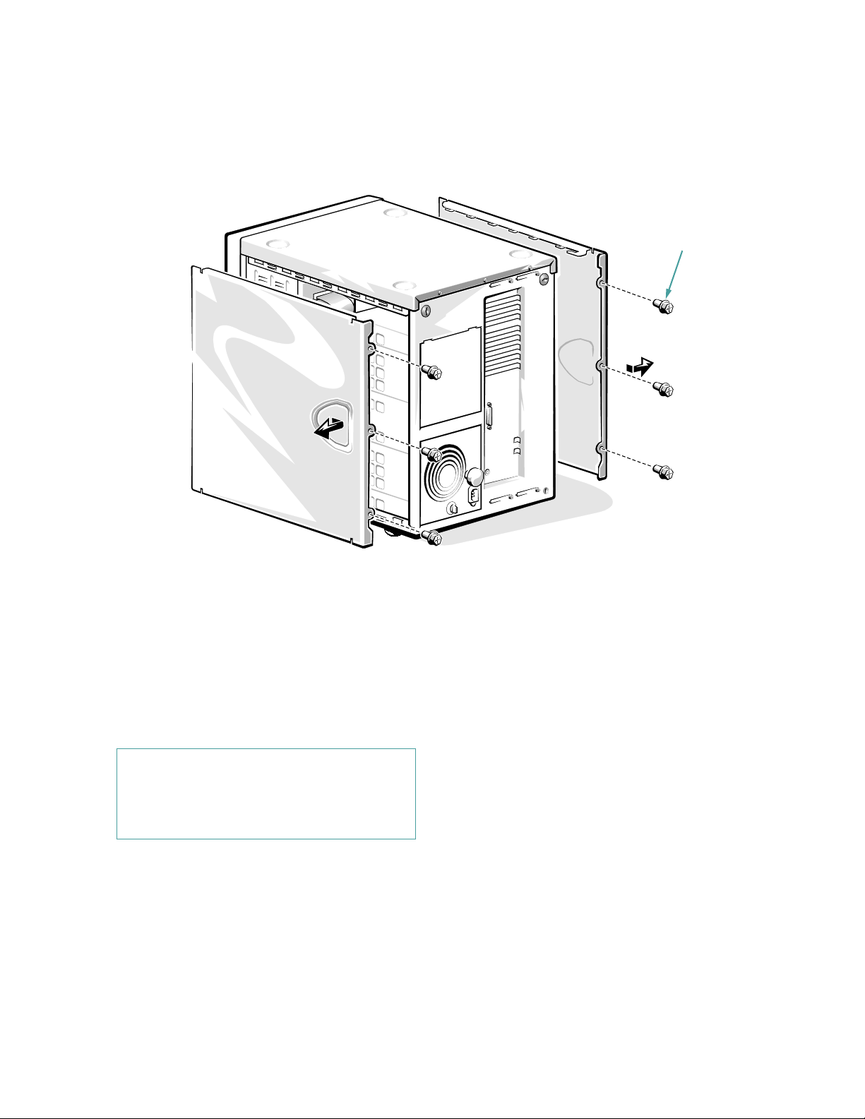
Figure 7-2. Removing the Computer Covers
screws (6)
Replacing the Computer Covers
Use the following procedure to replace a computer cover:
1. Check all cable connections, especially those that
might have come loose during your work. Fold
cables out of the way so that they do not catch on
the computer cover.
CAUTION: Make sure that there are no cables
or cable connectors lying on the top diskette
drive in the upper drive cage. Foreign objects
on top of the drive can interfere with drive
operation and permanently damage the drive.
2. Check that no tools or extra parts (including
screws) are left inside the computer.
3. Make sure the keylock is in the unlocked position.
4. Fit the cover over the side rail at the bottom of the
chassis, and slide it closed.
5. Secure the cover with the three screws.
6. Set the keylock to the locked position.
Checking Inside the Computer 7-3
Page 55

R
emoving the Front Bezel
I
nside the Chassis
Use the following procedure to remove the front bezel:
1. Remove the computer covers.
See the previous subsection, “Removing the Computer Covers.”
2. Release the two tabs on each side of the bezel.
3. Slide the front bezel straight forward.
tabs (4)
Figure 7-3. Removing the Front Bezel
In Figures 7-4 and 7-5, the computer cover is removed to
provide interior views from the left and right sides. These
illustrations also identify features on the front and back
of the computer. Refer to them to locate interior features
and components discussed later in this guide.
When you look inside the computer, note the direct current
(DC) power cables leading from the power supply or
optional power-supply paralleling board. These cables
supply power to the system board, small computer system interface (SCSI) backplane board, externally
accessible drives, and certain expansion cards that connect to external peripherals.
The flat ribbon cables are the interface cables for internal
drives. For non-SCSI drives, an interface cable connects
each drive to an interface connector on the system board
or on an expansion card. For SCSI devices, two interface
cables connect externally accessible SCSI devices and
the SCSI backplane board to a SCSI host adapter either
on the system board or on an expansion card.
The system board—the large, vertical printed circuit board
at the left side of the chassis near the back—holds the
computer’s control circuitry and other electronic components. Some hardware options are installed directly onto
the system board. The system board provides eight expan-
sion-card connectors. The external drive bays provide space
for up to four half-height drives, typically diskette drives,
CD-ROM drives, or tape drives. The internal drive bays
provide space for up to six half-height SCSI hard-disk
drives. These drives are connected to the SCSI host
adapter via the SCSI backplane board, which manages the
drive bays and monitors the drive environment, including
voltages and temperatures.
During an installation or troubleshooting procedure, you
may be required to change a jumper or switch setting on the
system board, an expansion card, or a drive. For information on the system board jumpers, see Appendix C,
“Jumpers and Switches.”
7-4 Dell PowerEdge 4100/180 and 4100/200 Systems Installation and Troubleshooting Guide
Page 56
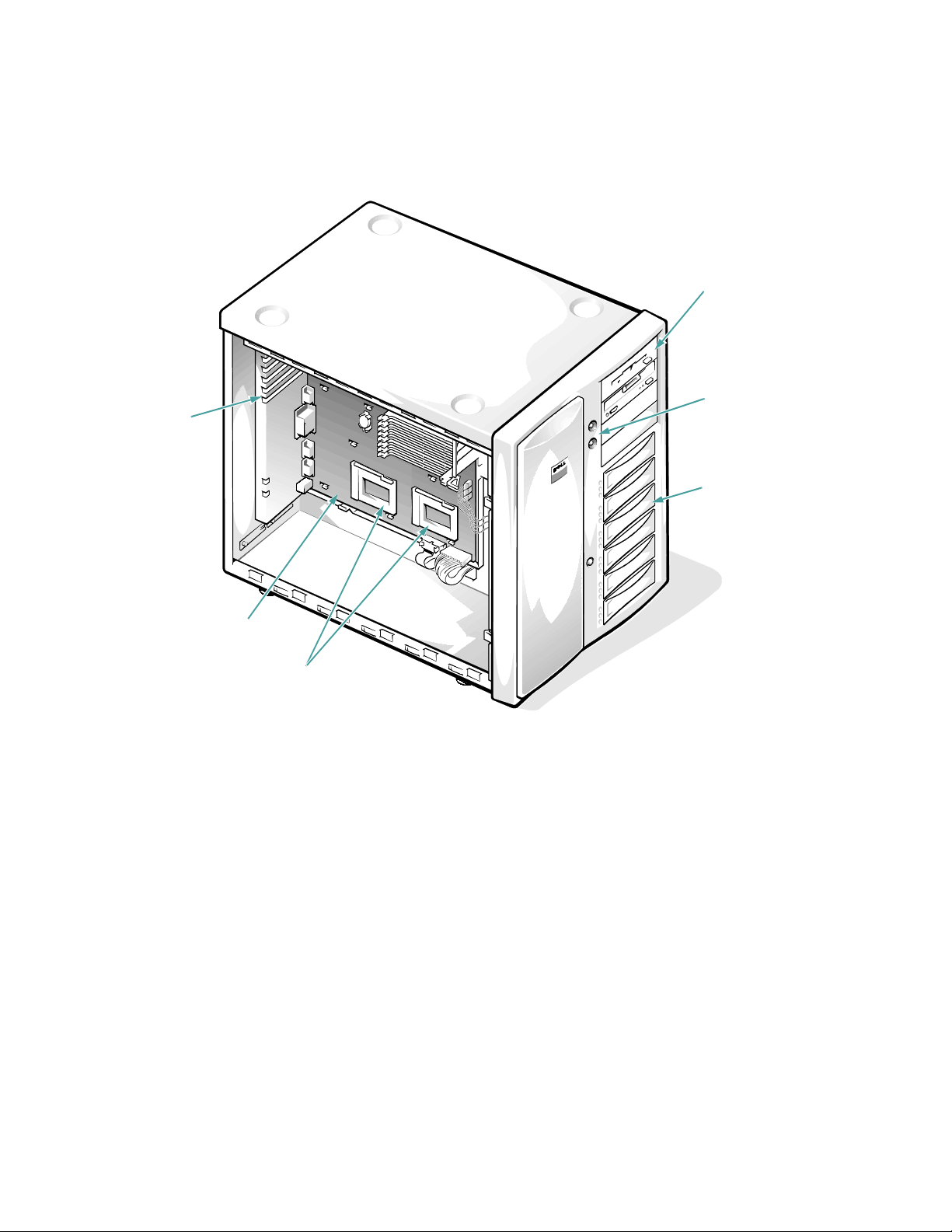
expansion slots
system board
microprocessor sockets
external drive bays (4)
control panel
internal drive bays (6)
Figure 7-4. Inside the Chassis—Front/Left Side View
Checking Inside the Computer 7-5
Page 57

external drive bays (4)
internal drive bays (6)
SCSI backplane
board
Figure 7-5. Inside the Chassis—Back/Right Side View
R
esponding to a Dell HIP Alert
Message
The Dell Hardware Instrumentation Package (HIP)
server management application program monitors critical
system voltages and temperatures, the system cooling
fans, and the status of the SCSI hard-disk drives in the
computer. The program generates alert messages that
appear in the simple network management protocol
(SNMP) trap log file. (More information about the Alert
Log window and options is provided in the Dell HIP
online help and the Dell HIP User’s Guide.)
Table 3-3 lists important HIP alert log messages, along
with their probable causes and recommended actions.
7-6 Dell PowerEdge 4100/180 and 4100/200 Systems Installation and Troubleshooting Guide
T
roubleshooting a Wet Computer
Liquid spills, splashes, and excessive humidity can cause
damage to the system. If an external device (such as a printer or an external drive) gets wet, contact the manufacturer
for instructions. If the computer gets wet, complete the
following steps:
1. Turn off the system, including any attached
peripherals, and disconnect all the alternating
current (AC) power cables from their power
sources.
Page 58

2. Remove the computer covers.
CAUTION: See “Protecting Against Electrostatic
Discharge” in the safety instructions at the front of
this guide.
See “Removing the Computer Covers” found earlier
in this chapter.
3. Let the computer dry for at least 24 hours.
Make sure that it is thoroughly dry before
proceeding.
4. Remove all expansion cards installed in the
computer.
5. Replace the computer covers, reconnect the system to AC power, and turn it on.
Does the system have power?
Ye s . Go to step 6.
No. See Chapter 11, “Getting Help,” for instructions
on obtaining technical assistance.
6. Turn off the system, disconnect it from AC power,
remove the left computer cover, and reinstall all
expansion cards you removed in step 4.
7. Replace the computer cover, and reconnect the
system to AC power.
8. Run the System Set Test Group in the system
diagnostics.
See Chapter 5, “Running the System Diagnostics.”
Do the tests complete successfully?
Ye s . The system is operating properly.
No. See Chapter 11, “Getting Help,” for instructions
on obtaining technical assistance.
T
roubleshooting a Damaged
Computer
If the computer was dropped or damaged, you should
check the computer to see if it functions properly. If an
external device attached to the computer is dropped or
damaged, contact the manufacturer of the device for
instructions or see Chapter 11, “Getting Help,” for information on obtaining technical assistance from Dell.
Follow these steps to troubleshoot a damaged computer:
1. Turn off the system, including any attached
peripherals, and disconnect all the AC power
cables from their power sources.
2. Remove the left computer cover.
CAUTION: See “Protecting Against Electrostatic Discharge” in the safety instructions at
the front of this guide.
See “Removing the Computer Covers” found earlier
in this chapter.
3. Check all the board and card connections in the
computer.
Check the following connections:
•
Expansion-card connections to the system board
•
Drive carrier connections to the SCSI backplane
board
4. Verify all internal cable and component
connections.
Make sure that all cables are properly connected and
that all components are properly seated in their connectors and sockets.
5. Replace the left computer cover and reconnect
the system to AC power.
6. Run the System Set Test Group in the system
diagnostics.
See Chapter 5, “Running the System Diagnostics.”
Do the tests complete successfully?
Ye s . The system is operating properly.
No. See Chapter 11, “Getting Help,” for instructions
on obtaining technical assistance.
T
roubleshooting the Battery
If an error message indicates a problem with the
battery or if the System Setup program loses the system
Checking Inside the Computer 7-7
Page 59

configuration information when the computer is turned
off, the battery may be defective.
Follow these steps to troubleshoot the battery:
1. Turn off the system, including any attached
peripherals, and disconnect all the AC power
cables from their power sources.
2. Remove the left computer cover.
See “Removing the Computer Covers” found earlier
in this chapter.
CAUTION: See “Protecting Against Electrostatic Discharge” in the safety instructions at
the front of this guide.
3. Check the connection of the coin cell battery to
the system board.
Is the battery firmly installed in the battery socket on
the system board?
Ye s . Go to step 5.
No. Go to step 4.
4. Reseat the battery in its socket.
Is the problem resolved?
Ye s . The battery was loose. You have fixed the
problem.
No. Go to step 5.
5. Replace the battery.
See “Replacing the Battery” in Chapter 8 for instructions on replacing the battery.
Is the problem resolved?
Ye s . The battery’s charge was low. You have fixed
the problem.
No. See Chapter 11, “Getting Help,” for instructions
on obtaining technical assistance.
T
roubleshooting Power Supply
Problems
The optional redundant power supplies in Dell PowerEdge 4100 systems are controlled by the power-supply
paralleling board. If a power-supply paralleling board is
installed, the two light-emitting diodes (LEDs) on the
back of the power supply (see Figure 7-6) signal the status of the power supply. If the red power-supply fault
indicator lights up, the power supply should be replaced.
locking
knob
power-supply fault
indicator
Figure 7-6. Power Supply Features
Replacing a Power Supply
Follow these steps to replace a power supply:
1. Disconnect the AC power cable from the power
outlet, then disconnect the other end of the cable
from the power supply.
Open the plastic strain-relief clip and remove the AC
power cable.
2. Turn the rotary switch on the power supply to the
“off” position, marked by a “0.”
3. Turn the locking knob counterclockwise to
release the power supply.
power-supply online
indicator
locking switch
7-8 Dell PowerEdge 4100/180 and 4100/200 Systems Installation and Troubleshooting Guide
Page 60

4. Slide the power supply out of the chassis (see Figure 7-7).
Figure 7-7. Removing the Power Supply
5. Check that the locking switch on the new power
supply is set to the “off” position, then slide the
power supply into the chassis.
6. Turn the locking knob clockwise until the replacement power supply is secured in the chassis.
7. Connect the AC power cable to the power supply
and to the power outlet.
Make sure that the AC power cable passes through
the plastic strain-relief clip.
8. Turn the locking switch on the power supply to
the “on” position, marked by an “I.”
If an optional power-supply paralleling board is
installed, the green online indicator on the power
supply should light up.
Troubleshooting Power Cable
Connections
1. Check the AC power outlet and power cable (see
“Checking Connections and Switches” in Chapter 2.
2. Turn off the system, including any attached
peripherals, and disconnect all the AC power
cables from their power sources.
3. Remove the computer covers.
See “Removing the Computer Covers” found earlier
in this chapter.
4. Check the cable connections listed in Table 7-1.
.
Table 7-1. Power Cable Connectors on the
Optional Power-Supply Paralleling Board
Connector Cable Connection
PWR1 To POWER1 connector on
system board
PWR2 To POWER2 connector on
system board
PWR3 To POWER3 connector on
system board
PWRFD To diskette drives and other
devices in external drive
bays
PWRSCSI To POWER connector on
SCSI backplane
T
roubleshooting a Cooling Fan
Three cooling fans are installed in the Dell PowerEdge
4100 system. Two fans are used to cool the computer; the
third cooling fan does not operate unless one of the other
two fans fails. If you observe that only one of the three
redundant cooling fans is operating, or the Dell HIP
server-management application program issues a fanrelated error message, replace the fan as described in the
following subsection.
Checking Inside the Computer 7-9
Page 61

Replacing a Cooling Fan
Follow these steps to replace a defective cooling fan.
WARNING: Only trained service technicians
should perform this procedure. Do not remove
the left computer cover with the power on
unless you are replacing a cooling fan. (Never
remove the right computer cover with the computer power on. There are high voltages in this
area that can cause bodily harm.)
Do not touch or attempt to service any components other than the cooling fan. Other
components could be damaged if you attempt
to service them with the computer power on.
1. Remove the left computer cover.
See “Removing the Computer Covers” found earlier
in this chapter.
2. Identify the defective cooling fan.
3. Disconnect the cooling fan’s power cable from the
FAN connector on the system board.
4. Depress the catch on the fan carrier (see Figure 7-8) and remove the fan carrier from the
chassis.
fan carrier
fan
catch
retention
tabs (2)
5. Remove the cooling fan from the fan carrier by
releasing the two fan retention tabs inside the carrier (see Figure 7-8).
6. Insert the replacement cooling fan in the carrier,
and snap the two fan retention tabs back into
position.
Orient the fan so that the power cable is at the upperright corner of the carrier.
7. Reinstall the fan carrier in the computer.
Insert the two tabs along the lower edge of the fan
carrier into the valences in the chassis, then raise the
fan carrier into position until the catch on the fan carrier snaps into place in the computer chassis.
8. Connect the cooling-fan power cable to the FAN
connector on the system board.
The fan should begin running.
9. Replace the left computer cover.
T
roubleshooting Expansion
Cards
If an error message indicates an expansion-card problem
or if an expansion card seems to perform incorrectly or
not at all, the problem could be a faulty connection, a
conflict with software or other hardware, or a faulty
expansion card. Follow these steps to troubleshoot
expansion cards:
1. Start the EISA Configuration Utility, and verify
that all Extended Industry-Standard Architecture (EISA) and Industry-Standard Architecture
(ISA) expansion cards have been configured
correctly. Save the configuration before exiting
the utility.
See Chapter 5, “Using the EISA Configuration Utility,” in the system User’s Guide for instructions.
2. Turn off the system, including any attached
peripherals, and disconnect all the AC power
cables from their power sources.
Figure 7-8. Replacing a Cooling Fan
7-10 Dell PowerEdge 4100/180 and 4100/200 Systems Installation and Troubleshooting Guide
Page 62

3. Remove the left computer cover.
See “Removing the Computer Covers” found earlier
in this chapter.
CAUTION: See “Protecting Against Electrostatic Discharge” in the safety instructions at
the front of this guide.
4. Verify that each expansion card is firmly seated
in its connector.
Are the expansion cards properly seated in their
connectors?
Ye s . Go to step 6.
No. Go to step 5.
5. Reseat the expansion cards in their connectors.
See “Removing an Expansion Card” and “Installing
an Expansion Card” in Chapter 8 for instructions on
removing and replacing expansion cards.
Is the problem resolved?
Ye s . The connection was loose. You have fixed the
problem.
No. Go to step 6.
6. Verify that the appropriate cables are firmly connected to their corresponding connectors on the
expansion cards.
For instructions on which cables should be attached
to specific connectors on an expansion card, see the
expansion card’s documentation.
Are the appropriate cables firmly attached to their
connectors?
Ye s . Go to step 8.
No. Go to step 7.
7. Reconnect the cable connectors to the appropriate connectors on the expansion cards.
Is the problem resolved?
Ye s . The cable connections were loose. You have
fixed the problem.
No. Go to step 8.
8. Inspect all jumpers and configuration switches on
each expansion card.
Most ISA expansion cards have configuration settings for an interrupt request (IRQ) line, a direct
memory access (DMA) channel, and a base-memory
or basic input/output system (BIOS) address. To
keep expansion cards from conflicting with each
other, you need to know both the starting memory
address and the amount of memory required by each
card. For instructions on jumpers and configuration
settings, see the expansion card’s documentation.
Is each expansion card configured correctly?
Ye s . Go to step 10.
No. Go to step 9.
9. Reconfigure the card according to the instructions in the card’s documentation.
Is the problem resolved?
Ye s . The memory configuration of the card was
incorrect. You have fixed the problem.
No. Go to step 10.
10. Inspect all configuration jumpers on the system
board to ensure that they are configured correctly
for any installed expansion cards.
For information on the configuration jumpers and
their settings, see Appendix C, “Jumpers and
Switches.”
Are the system board’s configuration jumpers set
correctly?
Ye s . Go to step 12.
No. Go to step 11.
11. Correct the system board’s configuration jumper
settings.
Is the problem resolved?
Ye s . You have fixed the problem.
No. Go to step 12.
12. Remove all expansion cards except the hard-disk
drive controller card (if one is installed).
See “Removing an Expansion Card” in Chapter 8 for
information on removing expansion cards.
Checking Inside the Computer 7-11
Page 63

13. Replace the left computer cover, reconnect the
system to AC power, and turn it on.
14. Enter the System Setup program, and update the
system configuration information.
See Chapter 4, “Using the System Setup Program,”
in the User’s Guide for instructions.
For any EISA and ISA expansion cards, enter the
EISA Configuration Utility, and update the configuration information.
See Chapter 5, “Using the EISA Configuration Utility,” in the system User’s Guide for instructions.
15. Run the RAM Test Group in the system
diagnostics.
See Chapter 5, “Running the System Diagnostics.”
Do the tests complete successfully?
Ye s . Go to step 17.
No. See Chapter 11, “Getting Help,” for information
on obtaining technical assistance.
16. Turn off the system, disconnect it from AC power,
and remove the left computer cover.
17. Reinstall one of the expansion cards you removed
in step 12, and repeat steps 13 though 15.
18. Run the RAM Test Group in the system
diagnostics.
Do the tests complete successfully?
Ye s . Go to step 20.
No. See Chapter 11, “Getting Help,” for information
on obtaining technical assistance.
19. Repeat steps 17 through 19 for each of the
remaining expansion cards that you removed in
step 12.
Have you reinstalled all of the expansion cards without encountering a test failure?
Ye s . You have fixed the problem.
No. See Chapter 11, “Getting Help,” for information
on obtaining technical assistance.
T
roubleshooting System Memory
A system memory problem can be a faulty dual in-line
memory module (DIMM) or a faulty system board. If a
random-access memory (RAM) error message appears,
the system probably has a memory problem.
When you turn on or reboot the system, the Caps Lock
and Scroll Lock indicators on the keyboard should flash
momentarily and then turn off. If the
in the System Setup program is set to
indicator should flash momentarily and then remain on;
otherwise, it should turn off. Abnormal operation of these
indicators can result from a defective DIMM in socket
DIMM A. Follow these steps to troubleshoot system
memory:
1. Turn on the system, including any attached
peripherals.
Does an error message appear indicating invalid system configuration information after the memory
count completes?
Ye s . Go to step 2.
No. Go to step 8.
2. Enter the System Setup program to check the
TOTAL MEMORY
See Chapter 4, “Using the System Setup Program,”
in the User’s Guide for instructions.
Does the amount of memory installed match the
TOTAL MEMORY
Ye s . Go to step 8.
No. Go to step 3.
3. Turn off the system, including any attached
peripherals, and disconnect all the AC power
cables from their power sources.
4. Remove the left computer cover.
See “Removing the Computer Covers” found earlier
in this chapter.
CAUTION: See “Protecting Against Electrostatic Discharge” in the safety instructions at
the front of this guide.
or
SYSTEM MEMORY
SYSTEM MEMORY
or
NUM LOCK
ON, the Num Lock
category.
category
setting?
7-12 Dell PowerEdge 4100/180 and 4100/200 Systems Installation and Troubleshooting Guide
Page 64

5. Reseat the DIMMs in their sockets.
See “Adding Memory” in Chapter 8 for instructions
on removing and replacing DIMMs.
6. Replace the computer cover, reconnect the system
to AC power, and turn it on.
7. Enter the System Setup program and check the
TOTAL MEMORY
Does the amount of memory installed match the
TOTAL MEMORY
Ye s . Go to step 8.
No. Go to step 9.
8. Reboot the system, and observe the monitor
screen and the Num Lock, Caps Lock, and Scroll
Lock indicators on the keyboard.
Does the monitor screen remain blank, and do the
Num Lock, Caps Lock, and Scroll Lock indicators
on the keyboard remain on?
Ye s . Go to step 9.
No. Go to step 11.
9. Turn off the system, disconnect it from AC power,
and remove the left computer cover.
10. If possible, swap the DIMM in socket DIMM A
with one of the same capacity, reboot the system,
and observe the monitor screen and the indicators on the keyboard.
Is the problem resolved?
Ye s . You have fixed the problem.
No. Go to step 11.
11. Run the RAM Test Group in the system
diagnostics.
See Chapter 5, “Running the System Diagnostics.”
Do the tests complete successfully?
Ye s . You have fixed the problem.
No. See Chapter 11, “Getting Help,” for instructions
on obtaining technical assistance.
SYSTEM MEMORY
or
SYSTEM MEMORY
or
category again.
setting?
T
roubleshooting the Video
Subsystem
Troubleshooting video problems involves determining
which of the following is the source of the problem: the
monitor, the monitor interface cable, the video memory,
or the video logic of the computer. You can also have a
high-resolution video expansion card installed, which
overrides the video logic of the computer.
The following procedure troubleshoots problems with the
video memory and video logic only. Before you begin,
perform the procedure found in “Troubleshooting the
Monitor” in Chapter 6 to determine whether or not the
monitor is the source of the problem.
If you have a high-resolution video expansion card, first
complete the steps in “Troubleshooting Expansion
Cards” found earlier in this chapter to verify that the card
is configured and installed correctly.
Follow these steps to troubleshoot the video subsystem:
1. Run the Video Test Group in the system
diagnostics.
See Chapter 5, “Running the System Diagnostics.”
Most of the tests in the Video Test Group are interactive; that is, you must respond before the
diagnostics continues with the next test.
Do the tests complete successfully?
Ye s . It is not a video hardware problem. Go to Chapter 4, “Finding Software Solutions.”
No. Go to step 2.
2. Turn off the system, including any attached
peripherals, and disconnect all the AC power
cables from their power sources.
3. Remove the left computer cover.
See “Removing the Computer Covers” found earlier
in this chapter.
CAUTION: See “Protecting Against Electrostatic Discharge” in the safety instructions at
the front of this guide.
Checking Inside the Computer 7-13
Page 65

4. Check the system-board configuration jumpers.
See Table C-1 for a list of the system board jumpers
and their settings.
Is the on-board video jumper set correctly?
Ye s . Go to step 9.
No. Go to step 5.
5. Correct the configuration jumper setting on the
system board.
6. Replace the left computer cover, and reconnect
the system to AC power.
7. Run the Video Test Group again.
Is the problem resolved?
Ye s . The on-board video jumper was set incorrectly.
You have fixed the problem.
No. Go to step 8.
8. Turn off the system, disconnect it from AC power,
and remove the left computer cover.
9. Determine whether a video expansion card is
installed.
Is a video expansion card installed?
Ye s . Go to step 10.
No. The built-in video controller is faulty. Go to
step 11.
10. Remove the video expansion card, and repeat
steps 11 and 12.
Do the tests complete successfully?
Ye s . The video expansion card is faulty. See Chapter 11, “Getting Help,” for instructions on obtaining
technical assistance.
No. Go to step 11.
11. See Chapter 11, “Getting Help,” for instructions
on obtaining technical assistance.
T
roubleshooting the System
Board
A system board problem can result from a defective system board component, a faulty power supply, or a
defective component connected to the system board. If an
error message indicates a system board problem, follow
these steps to find the problem:
1. Turn off the system, including any attached
peripherals, and disconnect all the AC power
cables from their power sources.
2. Remove the left computer cover.
See “Removing the Computer Covers” found earlier
in this chapter.
CAUTION: See “Protecting Against Electrostatic Discharge” in the safety instructions at
the front of this guide.
3. Remove all expansion cards except the hard-disk
drive controller card and the video expansion
card (if they are installed).
4. Replace the left computer cover, reconnect the
system to AC power, and turn it on.
5. For any EISA and ISA expansion cards, start the
EISA Configuration Utility, and update the configuration information.
See Chapter 5, “Using the EISA Configuration Utility,” in the system User’s Guide for instructions.
6. Enter the System Setup program, and update the
system configuration information.
See Chapter 4, “Using the System Setup Program,”
in the User’s Guide for instructions.
7. Run the System Set Test Group in the system
diagnostics.
See Chapter 5, “Running the System Diagnostics.”
Do the tests complete successfully?
Ye s . Go to step 8.
No. Go to step 12.
7-14 Dell PowerEdge 4100/180 and 4100/200 Systems Installation and Troubleshooting Guide
Page 66

8. Turn off the system, disconnect it from AC power,
and remove the computer cover.
9. Reinstall one of the expansion cards you removed
in step 3, and repeat steps 4 and 5.
10. Run the System Set Test Group again.
Do the tests complete successfully?
Ye s . Go to step 11.
No. Go to step 12.
11. Repeat steps 8, 9, and 10 for each of the remaining expansion cards you removed in step 3.
Have you reinstalled all of the expansion cards without encountering a test failure?
Ye s . Go to step 12.
No. The expansion card is faulty. See Chapter 11,
“Getting Help,” for instructions on obtaining technical assistance.
12. Disconnect the keyboard and reboot the system.
Does the system boot successfully?
Ye s . Go to step 13.
No. Go to step 14.
13. Swap the keyboard with a comparable working
keyboard, and run the System Set Test Group
again.
Do the tests complete successfully?
Ye s . You have fixed the problem.
No. Go to step 14.
14. See Chapter 11, “Getting Help,” for instructions
on obtaining technical assistance.
T
roubleshooting the Diskette
Drive Subsystem
If the monitor displays a system error message indicating
a diskette drive problem during execution of either the
boot routine or the system diagnostics, the problem may
be caused by any of the following conditions:
•
The system configuration settings do not match the
physical diskette subsystem configuration.
•
The diskette drive cables are not properly connected
or are faulty.
•
An expansion card is interfering with proper drive
operations.
•
A diskette drive may be improperly configured.
•
The diskette drive or tape drive is faulty.
•
The computer’s power supply is not providing sufficient power for the drives.
•
The computer’s diskette drive logic is faulty.
The troubleshooting procedures for the diskette drive
subsystem are divided into the following subsections:
•
“Checking the Diskette Drive Subsystem”
•
“Troubleshooting the Diskette Drive Subsystem”
•
“Troubleshooting a SCSI Tape Drive”
Before you begin the troubleshooting procedures, complete steps 1 and 2 in the next subsection, “Checking the
Diskette Drive Subsystem,” to verify that the system configuration information is correct for the installed diskette
drive(s).
If, after completing these steps, the system boots correctly and the monitor no longer displays a system error
message, the problem is resolved. If you continue to have
problems, however, proceed with the appropriate diskette
drive subsystem troubleshooting procedure.
Checking the Diskette Drive Subsystem
To verify that the diskette drive subsystem is operating
properly, follow these steps:
1. Enter the System Setup program, and verify that
the system is configured correctly for the
KETTE DRIVE A
See Chapter 4, “Using the System Setup Program,”
in the system User’s Guide for instructions.
and
DISKETTE DRIVE B
DIS-
categories.
Checking Inside the Computer 7-15
Page 67

2. If the system configuration settings are incorrect,
make the necessary corrections in the System
Setup program, and then reboot the system.
3. Run the Diskette Drives Test Group in the system
diagnostics to see whether the diskette drive subsystem now works correctly.
See Chapter 5, “Running the System Diagnostics,”
for more information.
Do the tests complete successfully?
Ye s . Continue with the next step in the procedure you
were performing.
No. See Chapter 11, “Getting Help,” for instructions
on obtaining technical assistance.
Diskette-Drive Subsystem
Troubleshooting
Follow these steps to troubleshoot the diskette drive
subsystem:
1. Turn off the system, including any attached
peripherals, and disconnect all the AC power
cables from their power sources.
2. Remove both computer covers.
See “Removing the Computer Covers” found earlier
in this chapter.
CAUTION: See “Protecting Against Electrostatic Discharge” in the safety instructions at
the front of this guide.
3. Check the diskette drive cabling.
Is the diskette drive securely connected to the proper
diskette drive interface cable connector? Is the diskette drive interface cable connector securely
connected to the interface connector (labeled
“FLOPPY”) on the system board? Is the drive’s DC
power cable firmly connected to the drive?
Ye s . Go to step 5.
No. Go to step 4.
4. Reconnect the cable connectors.
5. Replace the computer covers, reconnect the system to AC power, and turn on the system.
6. Run the Diskette Drives Test Group in the system
diagnostics to see whether the diskette drive subsystem now works correctly.
See Chapter 5, “Running the System Diagnostics,”
for more information.
Do the tests complete successfully?
Ye s . You have fixed the problem.
No. Go to step 7.
7. Repeat steps 1 and 2, and remove all expansion
cards.
See “Expansion Cards” in Chapter 8 for instructions.
8. Replace the computer covers, reconnect the system to AC power, and turn on the system.
9. Run the Diskette Drives Test Group in the system
diagnostics to see whether the diskette drive subsystem now works correctly.
Do the tests complete successfully?
Ye s. An expansion card may be conflicting with the
diskette drive logic, or you may have a faulty expansion card. Go to “Checking the Diskette Drive
Subsystem” found earlier in this chapter.
No. Go to step 10.
10. Repeat steps 1 and 2, and reinstall one of the
expansion cards you removed in step 7.
See “Removing an Expansion Card” and “Installing
an Expansion Card” in Chapter 8 for instructions.
11. Replace the computer covers, reconnect the system to AC power, and turn on the system.
12. Run the Diskette Drives Test Group in the system
diagnostics to see whether the diskette drive subsystem now works correctly.
Do the tests complete successfully?
Ye s . Go to step 13.
No. Go to step 14.
13. Repeat steps 10 through 12 until all expansion
cards have been reinstalled or until one of the
expansion cards prevents the system from booting from the Dell Server Assistant CD.
7-16 Dell PowerEdge 4100/180 and 4100/200 Systems Installation and Troubleshooting Guide
Page 68

14. Repeat steps 1 and 2. Verify that the drive’s ter-
minator is installed and that the drive-select
jumper is set to the DS1 position.
NOTE: Some diskette drives may require you to
remove the drive from the computer to access the terminator and drive-select jumper.
For information about the drive’s terminator and
drive-select jumper settings, refer to the documentation for the drive.
Is the drive configured correctly?
Ye s . Go to step 18.
No. Go to step 15.
15. Correct the drive-select jumper setting and terminator installation.
16. Replace the computer covers, reconnect the system to AC power, and turn on the system.
17. Run the Diskette Drives Test Group in the system
diagnostics to see whether the diskette drive subsystem now works correctly.
Do the tests complete successfully?
Ye s . You have solved the problem.
No. Go to step 18.
18. See Chapter 11, “Getting Help,” for instructions
on obtaining technical assistance.
Troubleshooting a SCSI Tape Drive
A SCSI tape drive can be installed in one of the externally accessible drive bays or an external device that
attaches to a SCSI host adapter connector on the back
panel of the computer. In either case, the SCSI tape drive
is controlled by a SCSI host adapter installed in the computer, which may also control other SCSI devices
connected to one or more SCSI cables. SCSI devices
often require device drivers for the particular operating
system being used by the computer system.
Tape drive problems often result from a defective tape
drive, a defective tape cartridge, or software. Follow
these steps to troubleshoot a SCSI tape drive:
1. Remove the tape that was in use when the problem occurred, and replace it with a tape that you
know is not defective.
Is the problem resolved?
Ye s . The original tape was defective. Replace it with
a new tape. You have fixed the problem.
No. Go to step 2.
2. Verify that any required SCSI device drivers are
installed on the hard-disk drive and are configured correctly.
See Chapter 3, “Installing and Configuring SCSI
Drivers,” in the system User’s Guide for instructions
on installing and configuring the SCSI device drivers
for the system’s built-in SCSI host adapter or Dell
PowerEdge Expandable RAID Controller host
adapter card. For any other type of SCSI host adapter
card, see the documentation that accompanied the
SCSI host adapter card.
Are the drivers installed and configured correctly?
Ye s . The SCSI device drivers were installed or configured incorrectly or were corrupted. You have
fixed the problem.
No. Go to step 3.
3. Reinstall the tape backup software as instructed
in the tape-backup software documentation.
Is the problem resolved?
Ye s . The tape backup software was corrupted. You
have fixed the problem.
No. Go to step 4.
4. Restart the system and check for the presence of
the tape drive during the option read-only memory (ROM) scan sequence.
Is the problem resolved?
Ye s . The drive is correctly cabled and is receiving
power. Go to step 9.
No. Go to step 5.
Checking Inside the Computer 7-17
Page 69

5. Turn off the system, including any attached
peripherals, and disconnect all the AC power
cables from their power sources.
6. Remove both computer covers.
See “Removing the Computer Covers” found earlier
in this chapter.
CAUTION: See “Protecting Against Electrostatic Discharge” in the safety instructions at
the front of this guide.
7. Check the SCSI cable connections to the tape
drive and to the SCSI host adapter connector. If
the tape drive is an internal device, check the DC
power cable connection to the tape drive.
Are the cables firmly connected?
Ye s . Go to step 9.
No. Go to step 8.
8. Reseat the cable connectors, replace the computer
covers, reconnect the system to AC power, and
turn it on.
Is the problem resolved?
Ye s . You have fixed the problem.
No. Go to step 9.
9. Turn off the system, including any attached
peripherals, and disconnect all the AC power
cables from their power sources. Then remove the
right computer cover.
10. Remove the tape drive. Then verify that the tape
drive is configured for a unique SCSI identification (ID) number and that the tape drive is
terminated or not terminated as appropriate.
See the documentation for the tape drive for instructions on selecting the SCSI ID and enabling or
disabling termination.
Is the tape drive configured correctly?
Ye s . Go to step 13.
No. Go to step 11.
11. Reconfigure the tape drive’s SCSI ID and termination settings as appropriate. Reinstall the tape
drive, replace the computer covers, reconnect the
system to AC power, and turn it on.
Is the problem resolved?
Ye s . The tape drive was configured incorrectly. You
have fixed the problem.
No. Go to step 12.
12. Turn off the system, including any attached
peripherals, and disconnect all the AC power
cables from their power sources. Then remove the
computer covers.
13. Replace the SCSI cable that connects the tape
drive to the SCSI host adapter. Replace the computer covers, reconnect the system to AC power,
and turn it on.
Is the problem resolved?
Ye s . You have fixed the problem.
No. See Chapter 11, “Getting Help,” for instructions
on obtaining technical assistance.
T
roubleshooting SCSI Hard-Disk
Drives
Hard-disk drive problems can be caused by a number of
conditions, including problems with the drive itself, the
SCSI backplane board, or an interface cable.
Drive Indicator Error Codes
The SCSI backplane board monitors the internal SCSI
hard-disk drives connected to the backplane board. In the
event of a drive failure, systems using the optional Dell
PowerEdge Expandable RAID Controller will issue the
following signals using the drive indicator lights adjacent
to each SCSI hard-disk drive:
•
If a drive shows signs of imminent failure, the drive
online indicator turns off and the drive fault indicator
blinks on briefly each second.
•
If a drive has failed, the drive online indicator turns
off and the drive fault indicator blinks off briefly
each second.
Other drive indicator patterns are listed in “SCSI HardDisk Drive Indicator Codes” in Chapter 3.
7-18 Dell PowerEdge 4100/180 and 4100/200 Systems Installation and Troubleshooting Guide
Page 70

SCSI Hard-Disk Drive Troubleshooting
Use the following procedure to troubleshoot a hard-disk
drive problem.
CAUTION: This troubleshooting procedure can
destroy data stored on the hard-disk drive. Before
you proceed, make sure you have backed up all
the files on the hard-disk drive.
1. If the on-board SCSI host adapter is being used to
control the SCSI backplane board, restart the
system and press <
program.
ON-BOARD SCSI A
Is the
Ye s . Go to step 3.
No. Go to step 2.
2. Change the
ON-BOARD SCSI A
and reboot the system.
Is the problem resolved?
Ye s . You have fixed the problem.
No. Go to step 3.
3. Verify that the SCSI device drivers are installed
and configured correctly.
See Chapter 3, “Installing and Configuring SCSI
Drivers,” in the system User’s Guide to determine
which drivers are required and how they should be
installed and configured.
Are the required SCSI device drivers installed and
configured correctly?
Ye s . Go to step 5.
No. Go to step 4.
4. Reinstall and/or reconfigure the required SCSI
device drivers. Then reboot the system.
Is the problem resolved?
Ye s . You have fixed the problem.
No. Go to step 5.
> to enter the System Setup
F2
category set to
category to
ENABLED
ENABLED
?
,
5. Remove the drive carrier from its bay, and check
the cable connections between the drive and the
drive carrier. Reinstall the drive.
Is the problem resolved?
Ye s . The drive carrier was not firmly seated in the
connector on the SCSI backplane board, or the cable
in the drive carrier was installed incorrectly. You
have fixed the problem.
No. Go to step 6.
6. Remove the drive carrier and install it in another
drive bay.
Is the problem resolved?
Ye s . The SCSI backplane board has a defective
connector. See Chapter 11, “Getting Help,” for
instructions on obtaining technical assistance.
No. Go to step 7.
7. Remove the computer covers.
CAUTION: See “Protecting Against Electrostatic Discharge” in the safety instructions at
the front of this guide.
8. Check the SCSI cable connections to the SCSI
backplane board and to the SCSI host adapter.
Check the DC power cable connection to the
SCSI backplane board.
The SCSI cable may be connected to the SCSI host
adapter on the system board, or to a SCSI host
adapter card in an expansion slot. See Chapter 10,
“Installing Drives in the Internal Bays,” for the location of the cable connectors on the SCSI backplane
board and the SCSI host adapter.
Are the cables firmly connected?
Ye s . Go to step 10.
No. Go to step 9.
Checking Inside the Computer 7-19
Page 71

9. Reseat the cable connectors, reconnect the computer and peripherals to their AC power sources,
and turn them on.
Is the problem resolved?
Ye s . The cable connections were faulty. You have
fixed the problem.
No. Go to step 10.
10. Partition and logically format the hard-disk
drive. If possible, restore the files to the drive.
To partition and logically format the drive, see the
documentation for the computer’s operating system.
Is the problem resolved?
Ye s . The hard-disk drive format was corrupted. You
have fixed the problem.
No. See Chapter 11, “Getting Help,” for instructions
on obtaining technical assistance.
7-20 Dell PowerEdge 4100/180 and 4100/200 Systems Installation and Troubleshooting Guide
Page 72
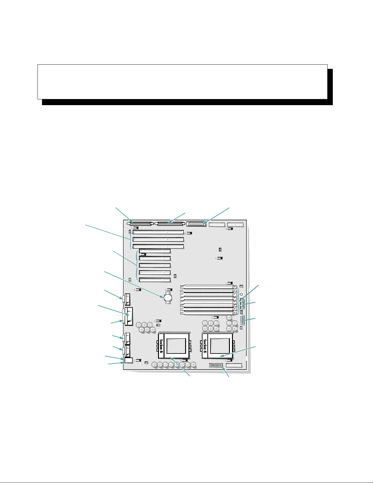
Chapter 8
Installing System Board Options
T
his chapter describes how to install the following
options:
•
Extended Industry-Standard Architecture (EISA),
Industry-Standard Architecture (ISA), and Peripheral Component Interconnect (PCI) expansion cards
diskette/tape drive interface
connector (FLOPPY)
EISA connectors
(EISA1 [top],
EISA2, and EISA3)
PCI connectors (PCI4 [top]
through PCI8)
battery connector
(BATTERY)
video connector
server-management
serial port connector
(REMOTE)
parallel port connector
serial port 2 connector
Ultra/Narrow SCSI host adapter
connector (SCSI CD-ROM)
•
Memory upgrades
•
Microprocessor upgrades
This chapter also includes instructions for replacing the
system battery, if necessary.
Use Figure 8-1 to locate the system board features mentioned in this chapter and elsewhere.
Ultra/Wide SCSI host adapter
connector (SCSI)
front of
system board
DIMM sockets
(DIMM A–DIMM H)
fan connectors (3)
speed and configuration
jumpers
serial port 1 connector
mouse connector
keyboard connector
secondary microprocessor
socket (PROCESSOR2)
Figure 8-1. System Board Features
primary
microprocessor
socket (PROCESSOR1)
server-management bus
connector (SMB BACKPLANE)
Installing System Board Options 8-1
Page 73

E
xpansion Cards
This computer can hold up to eight expansion cards, five
of which can be 32-bit PCI cards. The system accommodates a mix of 32-bit EISA master or slave cards, 32-bit
PCI cards, and 8- and 16-bit ISA cards. Figure 8-2 shows
examples of the different types of expansion cards.
The system board contains a total of eight expansion-card
connectors. An opening is available in the back panel of
the computer for each expansion-card connector, thus
providing eight usable expansion slots.
8-bit ISA expansion card
16-bit ISA expansion card
32-bit EISA expansion card
32-bit PCI expansion card
Figure 8-2. Expansion Cards
8-2 Dell PowerEdge 4100/180 and 4100/200 Systems Installation and Troubleshooting Guide
Page 74

Connectors EISA1 through EISA3 support 32-bit EISA
master or slave cards, and 8- and 16-bit ISA cards. Connectors PCI4 through PCI8 support 32-bit PCI cards.
Video expansion cards should be installed in one of the
three primary PCI slots (PCI6, PCI7, or PCI8).
EISA
expansion-card
connectors
(EISA1–EISA3)
PCI expansioncard connectors
(PCI4–PCI8)
Figure 8-3. Expansion-Card Connectors on the
System Board
Installing an Expansion Card
Follow this general installation procedure:
1. If you are installing an ISA expansion card, start
the EISA Configuration Utility, and add the new
expansion card to the configuration information.
See Chapter 5, “Using the EISA Configuration Utility,” in the system User’s Guide for instructions.
NOTES: If you are installing an EISA expansion
card, you should normally run the EISA Configuration Utility after installing the expansion card.
If you are installing a PCI expansion card, your system automatically performs any required PCI
configuration tasks during the boot routine.
2. Prepare the expansion card for installation, and
remove the left computer cover.
See “Removing the Computer Covers” in Chapter 7.
CAUTION: See “Protecting Against Electrostatic Discharge” in the safety instructions at
the front of this guide.
See the documentation that came with the expansion
card for information on configuring the card, making
internal connections, or otherwise customizing it for
the system.
3. Unscrew and remove the metal filler bracket that
covers the card-slot opening for the expansion
slot you intend to use.
4. If the expansion card is full-length, check that the
locking cam on the corresponding locking card
guide is in the raised or “unlocked” position.
Insert the end of the expansion card in the card
guide slot and lower the card into the chassis.
5. Insert the card-edge connector firmly into the
expansion-card connector on the chassis.
6. When the card is firmly seated in the connector
and the card-mounting bracket is flush with the
brackets on either side of it, secure the bracket
with the screw you removed in step 3.
If the expansion card is full-length, close the locking
cam on the card guide to secure the card.
7. Connect any cables that should be attached to the
card.
See the documentation that came with the card for
information about cable connections.
8. Replace the left computer cover, reconnect the
computer and peripherals to their power sources,
and turn them on.
9. Start the EISA Configuration Utility and add the
new expansion card to the configuration.
See Chapter 5, “Using the EISA Configuration Utility,” in the system User’s Guide for instructions.
NOTE: If you installed a PCI expansion card, the
system automatically performs any required PCI
configuration tasks during the boot routine.
Removing an Expansion Card
Follow this general procedure to remove an expansion
card:
1. If you are relocating or removing an ISA expansion card permanently, start the EISA
Installing System Board Options 8-3
Page 75

Configuration Utility and delete the expansion
card from the configuration.
See Chapter 5, “Using the EISA Configuration Utility,” in the system User’s Guide for instructions.
2. Remove the left computer cover.
See “Removing the Computer Covers” in Chapter 7.
CAUTION: See “Protecting Against Electrostatic Discharge” in the safety instructions at
the front of this guide.
3. If necessary, disconnect any cables connected to
the card.
4. Unscrew the card-mounting bracket.
If the expansion card is full-length, release the locking cam on the card guide.
5. Grasp the card by its top corners, and ease it out
of its connector.
6. If you are removing the card permanently, install
a metal filler bracket over the empty card-slot
opening.
NOTE: Installing a filler bracket over an empty
expansion slot is necessary to maintain Federal
Communications Commission (FCC) certification of
the system. The brackets also keep dust and dirt out
of the computer and aid in proper cooling and airflow inside the computer.
7. Replace the left computer cover, reconnect the
computer and peripherals to their power sources,
and turn them on.
8. If you are relocating or removing an EISA expansion card, start the EISA Configuration Utility,
and delete the expansion card from the configuration information.
See Chapter 5, “Using the EISA Configuration Utility,” in the system User’s Guide for instructions.
NOTE: If you removed a PCI expansion card, the
system automatically performs any required reconfiguration tasks during the boot routine.
A
dding Memory
The eight dual in-line memory module (DIMM) sockets on
the system board can accommodate 64 to 1024 megabytes
(MB) of dynamic random-access memory (DRAM). The
Dell PowerEdge 4100 systems use 72-bit, buffered,
extended-data out (EDO) DIMMs in these 168-pin sockets. The DIMM sockets are located near the right edge of
the system board (see Figure 8-1).
Memory Upgrade Kits
The system is upgradable to 1024 MB by installing combinations of 32- and 128-MB DIMMs. The DIMMs
should be rated at 60 nanoseconds (ns) or faster.
Table 8-1 shows several sample memory configurations.
Memory upgrade kits can be purchased from Dell as
needed.
DIMM Installation Guidelines
Starting with the socket farthest from the microprocessor
sockets, the DIMM sockets are labeled “DIMM A”
through “DIMM H” (see Figure 8-1).
When installing DIMMs, follow these guidelines:
•
Install a DIMM in socket DIMM A before socket
DIMM B, socket DIMM B before socket DIMM C,
and so on.
•
If you install different sizes of DIMMs, install them
in order of descending capacity, beginning with
socket DIMM A.
•
DIMMs need not be installed in pairs.
Table 8-1 illustrates several sample memory configurations based on these guidelines.
8-4 Dell PowerEdge 4100/180 and 4100/200 Systems Installation and Troubleshooting Guide
Page 76

Table 8-1. Sample DIMM Configurations
Total
Desired
Memory
DIMM A DIMM B DIMM C DIMM D DIMM E DIMM F DIMM G DIMM H
DIMM Sockets
64 MB 32 MB 32 MB None None None None None None
128 MB 32 MB 32 MB 32 MB 32 MB None None None None
128 MB 128 MB None None None None None None None
192 MB 128 MB 32 MB 32 MB None None None None None
320 MB 128 MB 128 MB 32 MB 32 MB None None None None
512 MB 128 MB 128 MB 128 MB 128 MB
1024 MB 128 MB 128 MB 128 MB 128 MB 128 MB 128 MB 128 MB 128 MB
Performing a Memory Upgrade
Use the following procedure to perform a memory
upgrade to the system board:
1. Remove the left computer cover.
See “Removing the Computer Covers” in Chapter 7.
the new memory total, which includes all newly
installed memory.
NOTE: If the memory total is incorrect, turn off and
disconnect the computer and peripherals from their
power sources, remove the computer cover, and
check all the installed DIMMs to make sure they are
seated properly in their sockets. Then repeat step 4.
CAUTION: See “Protecting Against Electrostatic Discharge” in the safety instructions at
the front of this guide.
The system detects that the new memory does not
match the system configuration information, which
is stored in nonvolatile random-access memory
(NVRAM). The monitor displays an error message
2. Locate the DIMM sockets in which you will
install or replace DIMMs.
Figure 8-1 shows the location of the DIMM sockets
on the system board.
3. Install or replace the DIMMs as necessary to
reach the desired memory total.
Follow the instructions in “Installing DIMMs” or
“Removing DIMMs” found later in this section, as
appropriate.
4. Replace the left computer cover, reconnect the
computer and peripherals to their power sources,
and turn them on.
After the system completes the power-on self-test
(POST) routine, it runs a memory test that displays
to that effect, ending with the following words:
Press <F1> to continue; <F2> to enter
System Setup.
5. Press <F2> to enter the System Setup program, and
check the
SYSTEM MEMORY
category in the system
data box on the System Setup screens.
The system should have already changed the value in
SYSTEM MEMORY
the
category to reflect the newly
installed memory. Verify the new total.
NOTE: The value of
SYSTEM MEMORY
is given in kilobytes. To convert kilobytes to megabytes, divide the
kilobyte total by 1024.
If the total is incorrect, one or more of the DIMMs
may not be installed properly. Repeat this procedure
again, checking to make sure the DIMMs are firmly
seated in their sockets.
Installing System Board Options 8-5
Page 77

6. Enter the EISA Configuration Utility. Then save
the configuration and exit the utility.
Running the EISA Configuration Utility and saving
the configuration is required for the system to recognize the newly installed DIMM(s). See Chapter 5,
“Using the EISA Configuration Utility,” in the User’s
Guide for instructions on running the utility and sav-
ing the configuration.
7. Run the RAM Test Group in the system
diagnostics.
See Chapter 5, “Running the System Diagnostics,”
for information.
2.
notch
1.
Installing DIMMs
Install DIMMs starting with socket DIMM A, located
farthest from the microprocessor sockets, and working
towards DIMM H. If a DIMM is already installed in the
socket you need, you must remove it. Follow the instructions in the next subsection, “Removing DIMMs,” if
appropriate.
To install a DIMM, follow these steps:
1. Press the ejectors on the DIMM socket down and
outward as shown in Figure 8-4 to allow the
DIMM to be inserted in the socket.
2. Align the DIMM’s edge connector with the slot in
the center of the DIMM socket, and insert the
DIMM in the socket.
The card-edge connector on the DIMM is keyed
using two notches so that the DIMM can be installed
in the socket in only one way (see Figure 8-4).
3. Press down on the two outer edges of the DIMM
with your thumbs while pulling up on the ejectors
with your index fingers to lock the DIMM into the
socket.
When the DIMM is properly seated in the socket, the
ejectors on the DIMM socket should align with the
ejectors on the other DIMM sockets.
Figure 8-4. Installing a DIMM
4. Continue with step 4 of “Performing a Memory
Upgrade” found earlier in this section.
Removing DIMMs
To remove a DIMM, press down and outward on the
ejectors on each end of the socket until the DIMM pops
out of the socket (see Figure 8-5).
press down and out
2.
1.
Figure 8-5. Removing a DIMM
8-6 Dell PowerEdge 4100/180 and 4100/200 Systems Installation and Troubleshooting Guide
Page 78

U
pgrading the Microprocessor or
Installing a Secondary
Microprocessor
In addition to the zero insertion force (ZIF) socket for the
primary microprocessor on the system board, there is a
second ZIF socket to accommodate a secondary microprocessor. The secondary microprocessor must have the
same operating frequency as the primary microprocessor.
For example, if the system has a 180 megahertz (MHz)
Pentium Pro primary microprocessor, your secondary
microprocessor must also be a 180-MHz Pentium Pro
microprocessor.
NOTE: If you are upgrading a system by installing a secondary microprocessor, you must order a microprocessor
upgrade kit from Dell. The upgrade kit from Dell contains the correct version of the microprocessor for use as
a secondary microprocessor. Not all versions of the Pentium Pro microprocessor will work properly as a
secondary microprocessor.
The following items are included in a microprocessor
upgrade kit:
•
The new microprocessor chip
•
A new heat sink
•
A new heat sink clip
•
A new snap-in badge
Use the following procedure to remove the old microprocessor and install the upgrade or to add a second
microprocessor.
1. Remove the left computer cover.
See “Removing the Computer Covers” in Chapter 7.
2. Remove the metal clip that secures the heat sink
to the microprocessor socket.
CAUTION: Never remove the heat sink from a
microprocessor unless you intend to remove
the microprocessor. The heat sink is necessary
to maintain proper thermal conditions.
WARNING: The microprocessor chip and heat
sink can get extremely hot. Be sure the microprocessor has had sufficient time to cool before
you touch it.
Press down on the folded part of the clip with a small
screwdriver to release the clip (see Figure 8-6).
press here to
r e l e a s e c l i p
microprocessor securing
clip hooks over tabs on
front and back of socket
Figure 8-6. Microprocessor Securing Clip
CAUTION: See “Protecting Against Electrostatic Discharge” in the safety instructions at
the front of this guide.
3. Remove the heat sink.
The thermal interface pad is bonded to the heat sink
and will remain attached to the old heat sink.
4. Remove the microprocessor chip from the socket.
CAUTION: Be careful not to bend any of the
pins when removing the microprocessor chip
from its socket. Bending the pins can permanently damage the microprocessor chip.
Installing System Board Options 8-7
Page 79

To remove the microprocessor chip, pull the socket
release lever straight up until the chip is released (see
Figure 8-7). Then lift the chip out of the socket.
Leave the release lever up so that the socket is ready
for the new microprocessor.
microprocessor chip
rectangular area. The gold finger points toward
pin 1, which is also uniquely identified by a square
pad.
pin-1 corner
(gold finger and square pad)
Figure 8-8. Pin-1 Identification
microprocessor
socket
release lever
Figure 8-7. Removing the Microprocessor
5. Unpack the new microprocessor.
CAUTION: Be careful not to bend any of the
pins when unpacking the microprocessor chip
from its socket. Bending the pins can permanently damage the microprocessor chip.
If any of the pins on the microprocessor appear bent,
see Chapter 11, “Getting Help,” for instructions on
obtaining technical assistance from Dell.
6. Align the pin-1 corner of the microprocessor chip
(see Figure 8-8) with the pin-1 corner of the
microprocessor socket.
NOTE: Identifying the pin-1 corners is critical to
positioning the chip correctly.
Identify the pin-1 corner of the microprocessor by
turning the chip over and locating the tiny gold finger that extends from one corner of the large central
7. Install the microprocessor chip in the socket (see
Figure 8-9).
CAUTION: Positioning the microprocessor
incorrectly can permanently damage the chip
and the computer when you turn on the
system.
If the release lever on the microprocessor socket is
not all the way up, move it to that position now.
With the pin-1 corners of the chip and socket
aligned, set the chip lightly in the socket and make
sure all pins are matched with the correct holes in
the socket. Because the system uses a ZIF microprocessor socket, there is no need to use force (which
could bend the pins if the chip is misaligned). When
the chip is positioned correctly, it should drop down
into the socket with minimal pressure.
CAUTION: When placing the microprocessor
chip in the socket, be sure that all of the pins
on the chip go into the corresponding holes of
the socket. Be careful not to bend the pins.
When the chip is fully seated in the socket, rotate the
socket release lever back down until it snaps into
place, securing the chip.
8-8 Dell PowerEdge 4100/180 and 4100/200 Systems Installation and Troubleshooting Guide
Page 80
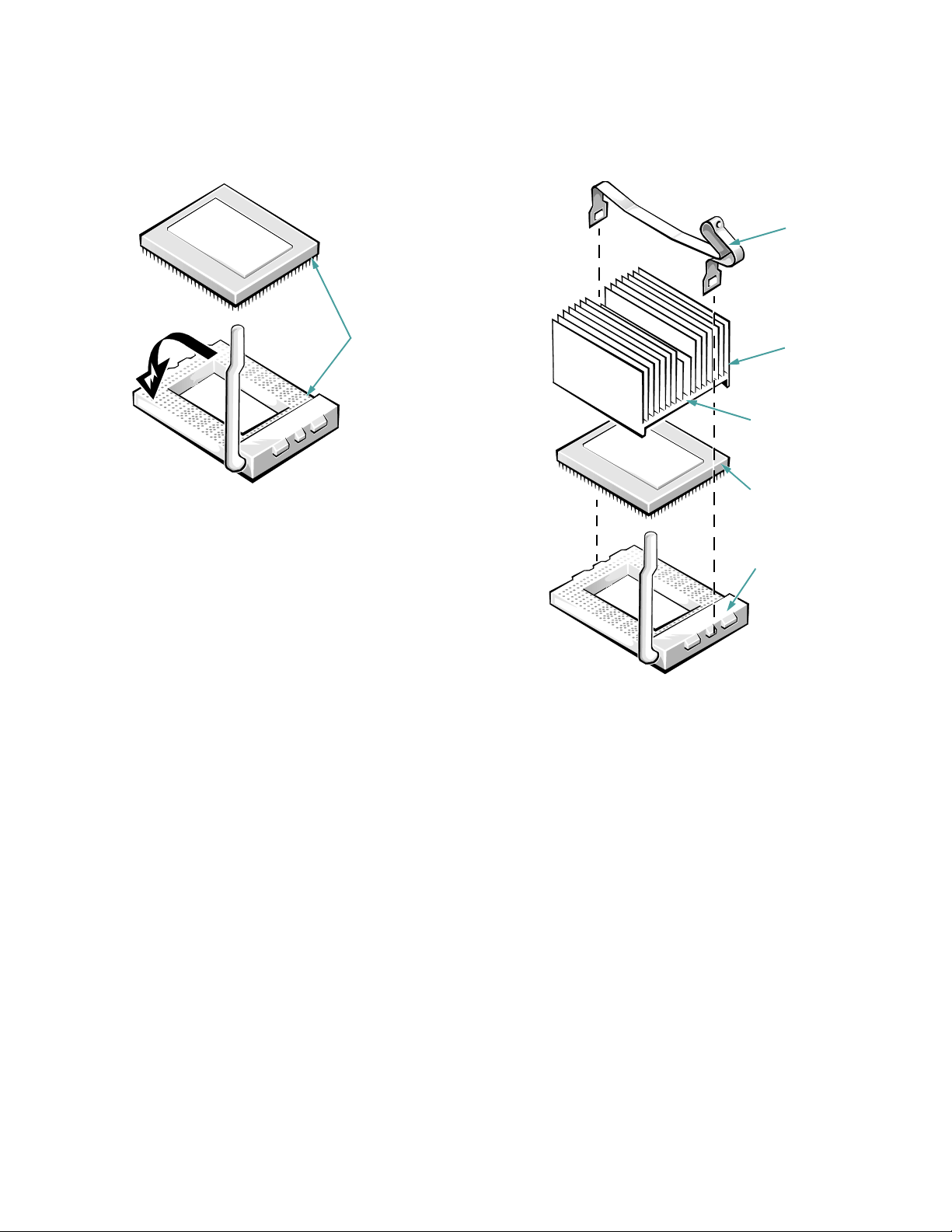
clip
pin-1 corners of
chip and socket
aligned
Figure 8-9. Installing the Microprocessor
Chip
8. Place the new heat sink (with its bonded thermal
interface pad) on top of the microprocessor chip
(see Figure 8-10).
heat sink
thermal pad
(bonded to heat
sink)
microprocessor
chip
microprocessor
socket
Figure 8-10. Installing the Heat Sink
9. Replace the microprocessor securing clip.
Orient the clip as shown in Figure 8-10, and hook the
unfolded end of the clip over the tab on the edge of
the socket facing the front of the computer. Then
press down on the folded end of the clip to snap the
clip over the tab on the back of the socket.
10. Change the microprocessor-speed jumper setting
to correspond to the new microprocessor’s operating frequency.
The microprocessor’s speed jumper should be set for
the installed microprocessor’s rated internal speed.
For example, for a 200-MHz Pentium Pro processor,
a jumper plug should be installed on the jumper
Installing System Board Options 8-9
Page 81

labeled “200MHZ.” (See Appendix C, “Jumpers and
Switches,” for more information on jumper
locations.)
11. Replace the left computer cover.
12. If you have upgraded the microprocessor to a
faster one, remove the old badge from the front of
the computer bezel and install the new badge:
a. Remove the bezel according to the instructions in
“Removing the Front Bezel” in Chapter 7.
b. The badge is secured to the front bezel with three
metal tabs. Press on all three tabs at once to release the detent that holds the badge in place, and
then push the tabs out of the front bezel. To install
the new badge, insert the three metal tabs through
the slots in the front bezel and press on the badge
until the detents on the tabs lock into place.
c. Replace the front bezel.
13. Reconnect your computer and peripherals to
their power sources, and turn them on.
As the system boots, it detects the presence of the
new microprocessor and automatically changes the
system configuration information in the System
Setup program.
14. Press <
check that the
egories match the new system configuration.
See Chapter 4, “Using the System Setup Program,”
in the system User’s Guide for instructions.
15. Run the system diagnostics to verify that the new
microprocessor is operating correctly.
See Chapter 5, “Running the System Diagnostics,”
for information.
R
eplacing the Battery
The system battery maintains system configuration, date,
and time information in a special section of memory
when the system is turned off.
> to enter the System Setup program, and
F2
PROCESSOR 1 and PROCESSOR 2
cat-
The operating life of the battery ranges from two to five
years, depending on how the system is used (for example,
if the system is on most of the time, the battery gets little
use and thus lasts longer). The battery may need replacing if an incorrect time or date is displayed during the
boot routine along with a message such as:
Time-of-day not set — please run SETUP
program
Strike the F1 key to continue, F2 to run
the setup utility
or
Invalid configuration information — please
run SETUP program
Strike the F1 key to continue, F2 to run
the setup utility
To determine if the battery needs replacing, reenter the
time and date through the System Setup program. Turn
off the system for a few hours, and then turn it on again.
Enter the System Setup program. If the date and time are
not correct in the System Setup program, replace the
battery.
NOTES: Some software may cause the system time to
speed up or slow down. If the system seems to operate
normally except for the time kept in the System Setup program, the problem may be caused by software rather than
by a defective battery.
If the system is turned off for long periods of time (for
weeks or months), the NVRAM may lose its system configuration information. This situation is not caused by a
defective battery.
The system can be operated without a battery; however,
the system configuration information maintained by the
battery in NVRAM is erased each time the computer is
turned off. Therefore, the system configuration information must be reentered and the options reset each time the
system boots until the battery is replaced.
The battery is a 3.0-volt (V), coin-cell CR2450-type battery. To remove the battery, follow these steps:
1. If possible, enter the System Setup program and
make a printed copy of the system setup screens.
See Chapter 4, “Using the System Setup Program,”
in the system User’s Guide for instructions.
8-10 Dell PowerEdge 4100/180 and 4100/200 Systems Installation and Troubleshooting Guide
Page 82

2. Remove the left computer cover.
See “Removing the Computer Covers” in Chapter 7.
CAUTION: See “Protecting Against Electrostatic Discharge” in the safety instructions at
the front of this guide.
3. Remove the battery.
Pry the battery out of its socket with your fingers or a
blunt, nonconductive object, such as a plastic
screwdriver.
4. Install the new battery with the “+” side facing up
(see Figure 8-11).
battery
BATTERY socket
5. Replace the left computer cover, reconnect the
computer and peripherals to their power sources,
and turn them on.
6. Enter the System Setup program to confirm that
the battery is operating properly.
Enter the correct time and date through the System
Setup program’s
TIME
and
DATE
categories. Also
reenter any system configuration information that is
no longer displayed on the system setup screens, and
then exit the System Setup program.
7. Turn the computer and peripherals off, and leave
them off for at least an hour.
8. After an hour, turn on the system and enter the
System Setup program. If the time and date are
still incorrect, see Chapter 11, “Getting Help,” for
instructions on obtaining technical assistance.
Figure 8-11. Battery Removal
Installing System Board Options 8-11
Page 83

8-12 Dell PowerEdge 4100/180 and 4100/200 Systems Installation and Troubleshooting Guide
Page 84
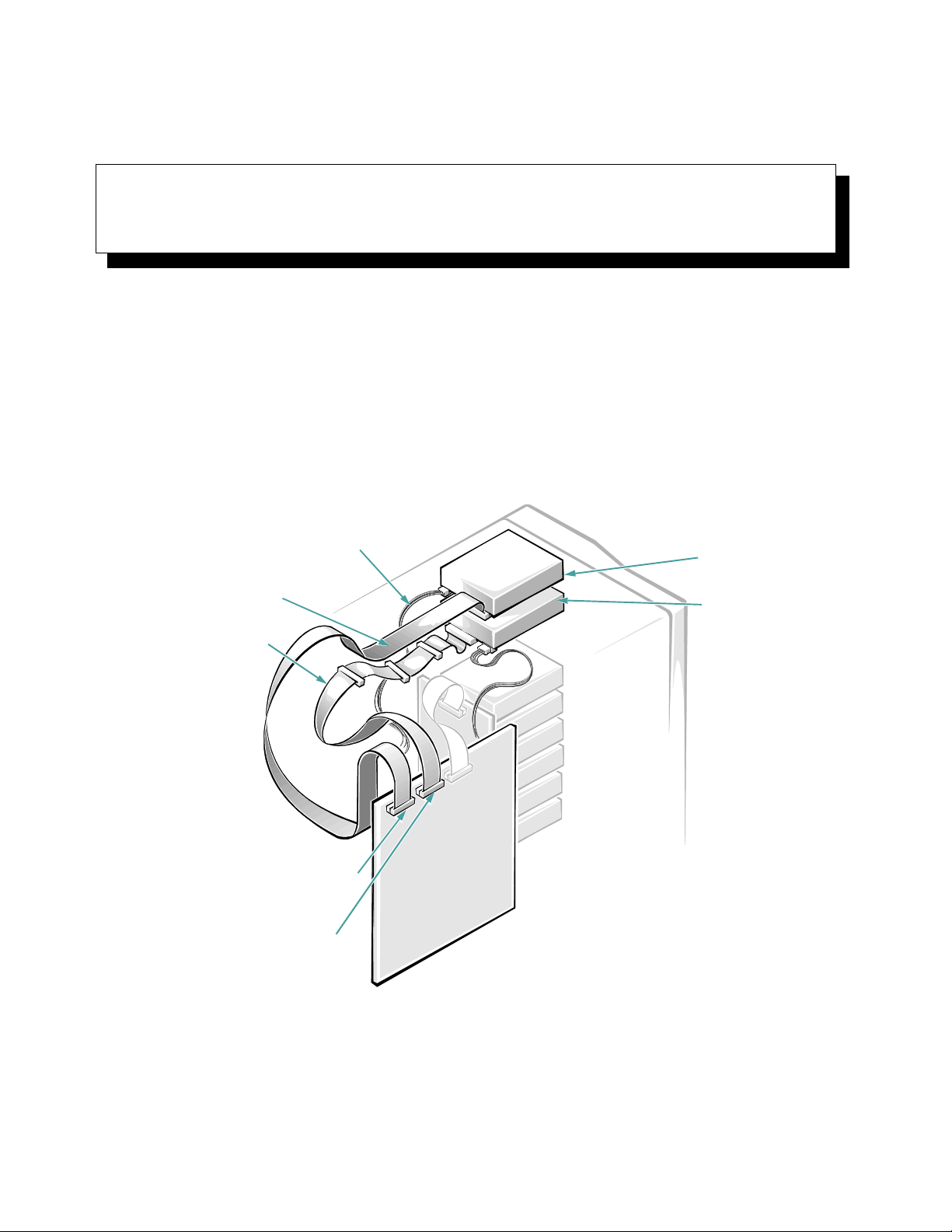
Chapter 9
Installing Drives in the External Bays
T
he external drive bays at the front of the Dell PowerEdge 4100 system hold up to four user-accessible, halfheight 5.25- or 3.5-inch devices, typically diskette, tape,
CD-ROM, or digital audio tape (DAT) drives. A 3.5-inch
diskette drive and small computer system interface
(SCSI) CD-ROM drive are standard in the first and second drive bays. The diskette drive is controlled by the
system board’s built-in diskette drive controller, whereas
DC power cable
diskette/tape
drive interface
cable
Ultra/Narrow
SCSI cable
the CD-ROM drive is connected to the system board’s
built-in Ultra/Narrow SCSI controller. Two additional
drives of your choice can be installed in the lower two
external drive bays. See Figure 9-1 for a general view of
the various drives, control cables, and power cables in the
external drive bays.
diskette drive
SCSI CD-ROM drive
diskette/tape drive interface
connector (FLOPPY)
Ultra/Narrow SCSI host adapter
connector (SCSI CD-ROM)
Figure 9-1. External Drive Bay Hardware
Installing Drives in the External Bays 9-1
Page 85
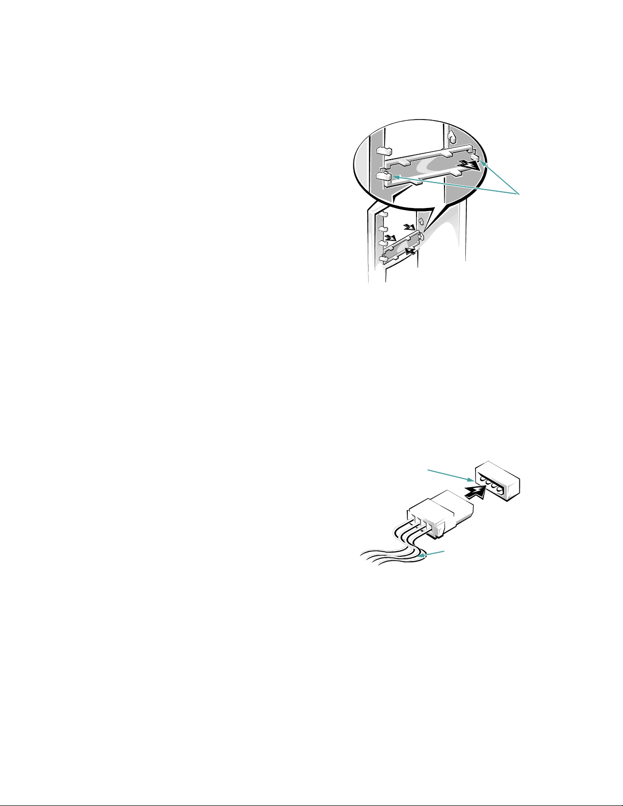
B
efore You Begin
This chapter describes how to install the following
options:
•
Drives that use the computer’s built-in diskette drive
controller.
•
Tape drives that use a controller card
NOTE: If you are installing a SCSI hard-disk drive, see
Chapter 10, “Installing Drives in the Internal Bays.”
In order to remove or install drives in the external bays,
you must remove the computer covers and front bezel
according to the instructions in “Removing the Computer
Covers” and “Removing the Front Bezel” in Chapter 7.
To protect the inside of the computer from foreign particles, a plastic front-panel insert covers each empty
external drive bay. Before you install a drive in an empty
bay, you must first remove the front-panel insert.
Whenever you remove a drive, be sure to replace the
front-panel insert over the empty bay.
Figure 9-2. Removing a Front-Panel Insert
C
onnecting the Drive
tabs
Removing and Replacing Front-Panel
Inserts
To remove the front-panel insert for a drive bay you
intend to use, first remove the front bezel as instructed in
“Removing the Front Bezel” in Chapter 7. Then, facing
the inside of the front bezel, press against the center of
the insert with your thumbs until the insert bows sufficiently to loosen the tabs on the sides of the insert (see
Figure 9-2). Pull the insert out of the bezel.
To replace a front-panel insert, position the insert over
the bay opening from the inside of the front bezel and
carefully press the insert into place. A tab on each side of
the insert snaps into a corresponding latch on the inside
of the front bezel.
This section describes the power input connectors and
interface connectors on the backs of most drives.
Figure 9-3 shows the 4-pin power input connector, where
you connect a direct current (DC) power cable from the
system power supply or optional power-supply paralleling board.
power input connector
on the drive
DC power cable (from
the power supply)
Figure 9-3. Power Connectors
9-2 Dell PowerEdge 4100/180 and 4100/200 Systems Installation and Troubleshooting Guide
Page 86
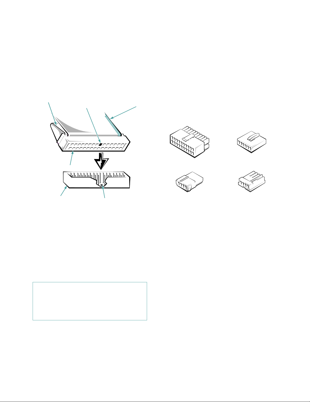
The power connectors are keyed to avoid incorrect insertion; do not force two connectors together if they do not
fit properly.
A ribbon cable (see Figure 9-4) functions as the interface
cable for most types of drives.
pull tab
key
(blocked hole)
colored strip on
ribbon cable
DC Power Cables
Each drive in the external drive bays must connect to a
4-wire DC power cable from the system power supply or
optional power-supply paralleling board. The connectors
on this cable are labeled “FD1,” “FD2,” “FD3,” “FD4,”
and “FD5.” Connectors FD1 through FD4 are used for
5.25-inch devices, whereas connector FD5 is used for the
standard 3.5-inch diskette drive. Before connecting a
drive to a power cable, refer to Figure 9-5 to identify the
correct cable connector to use for the drive.
interface connector
header connector
key (cut-off pin)
Figure 9-4. Header Connector
Most interface connectors are keyed for correct insertion;
that is, a notch or a missing pin on one connector matches
a tab or a filled-in hole on the other connector. Keying
ensures that the pin-1 wire in the cable (indicated by the
colored strip along one edge of the cable) goes to the
pin-1 ends of the connectors on both ends. A header con-
nector is usually keyed by the omission of one of its pins
with the corresponding hole filled in on the connector on
the cable (see Figure 9-4).
CAUTION: When connecting an interface cable,
do not reverse the interface cable (do not place the
colored strip away from pin 1 of the connector).
Reversing the cable prevents the drive from operating and could damage the controller, the drive,
or both.
system board
connector
5.25-inch drive
connector
system board
connector
3.5-inch drive
connector
Figure 9-5. DC Power Cable Connectors
I
nstalling SCSI Devices in the
External Bays
SCSI devices in the external drive bay (such as CD-ROM
drives and tape drives) are controlled by the Ultra/
Narrow SCSI controller on the system board.
SCSI Configuration Information
Although SCSI devices are installed essentially the same
way as other devices, their configuration requirements
are different. To configure SCSI devices installed in the
external bays, follow the guidelines in the following
subsections.
Installing Drives in the External Bays 9-3
Page 87

SCSI ID Numbers
Each device attached to the Ultra/Narrow SCSI host
adapter must have a unique SCSI identification (ID)
number from 0 to 7.
When SCSI devices are shipped from Dell, the default
SCSI ID numbers are assigned as follows:
•
The computer’s built-in Ultra/Narrow SCSI host
adapter is configured through the basic input/output
system (BIOS) as SCSI ID 7.
•
A SCSI tape drive is configured as SCSI ID 6 (the
default ID number for a tape drive).
•
A SCSI CD-ROM drive is usually configured as
SCSI ID 5.
NOTE: There is no requirement that SCSI ID numbers be
assigned sequentially or that devices be attached to the cable in
order by ID number.
Device Termination
SCSI logic requires that the two devices at opposite ends
of the SCSI chain be terminated and that all devices in
between be unterminated.
Before installing SCSI devices in the computer, you must
configure the terminators on the SCSI device(s) to conform to the following guidelines:
•
A single SCSI device (such as the standard
CD-ROM drive) is terminated.
•
If two or more SCSI devices are installed, connect
the devices as follows:
— Attach one of the devices to the end connector on the
SCSI cable, and leave the terminator enabled on that
device.
— The other end of the SCSI cable connects to the com-
puter’s built-in Ultra/Narrow SCS I host adapter or to an
optional SCSI host adapter card.
— Disable the terminators on all other devices you attach
to the cable.
The standard SCSI CD-ROM drive is configured as the
last device on the SCSI cable. Therefore, any additional
devices attached to the cable should have their terminators disabled.
See the documentation provided with the SCSI device for
information on disabling the device’s terminator.
SCSI Cable
CAUTION: Dell recommends that you use
only SCSI cables purchased from Dell. SCSI
cables purchased elsewhere are not guaranteed
to work reliably with the Dell PowerEdge 4100
systems.
The 50-pin Ultra/Narrow SCSI cable has five connectors:
•
The connector at the end of the cable farthest away
from the other four connectors attaches to the SCSI
host adapter connector labeled “SCSI CD-ROM” on
the system board.
•
The four connectors on the cable attach to devices in
the external drive bays.
Installing a SCSI Device
To install an external SCSI device that uses the built-in
Ultra/Narrow SCSI controller, follow these steps:
1. Prepare the drive for installation.
Ground yourself by touching an unpainted metal surface on the back of the computer, unpack the drive,
and compare the jumper and switch settings with
those in the drive documentation. (See “SCSI Configuration Information” found earlier in this chapter
for information on setting the drive’s SCSI ID number and enabling termination [if required].) Change
any settings necessary for this system’s configu-
ration.
If the drive does not already have drive rails
attached, attach a drive rail to each side of the drive.
Orient the drive rails as shown in Figure 9-6. Secure
each drive rail to the drive with a screw in each of
the lower slotted screw holes on the drive rail.
9-4 Dell PowerEdge 4100/180 and 4100/200 Systems Installation and Troubleshooting Guide
Page 88

Figure 9-6. Attaching Drive Rails
2. Remove the computer covers and front bezel.
See “Removing the Computer Covers” and “Remov-
ing the Front Bezel” in Chapter 7.
CAUTION: See “Protecting Against Electrostatic Discharge” in the safety instructions at
the front of this guide.
3. Slide the new drive into its bay until it snaps
securely into place.
If necessary, you can adjust drive alignment by
repositioning one or both rails.
4. Connect a DC power cable and one of the connectors on the Ultra/Narrow SCSI cable to the back
of the drive (see Figure 9-7).
If other installed drives are in the way, temporarily
move them out of the way. Press in on the plastic
drive rails at the front of the bay to disengage a
drive, and then slide the drive slightly toward the
front of the chassis.
Refer to “DC Power Cables” (found earlier in this
chapter) to determine the correct DC power cable
connector to use for the drive. Plug the DC power
cable connector into the 4-pin power input connector
on the back of the drive.
Select the connector on the Ultra/Narrow SCSI cable
that most easily reaches the new SCSI device, and
press the interface cable connector firmly into the
drive’s interface connector.
If you moved other drives at the beginning of this
step, snap them back into place.
Installing Drives in the External Bays 9-5
Page 89

DC power cable
Ultra/Narrow
SCSI cable
Ultra/Narrow SCSI host adapter
connector (SCSI CD-ROM)
Figure 9-7. Cable Connections for a SCSI Device in the External Drive Bays
SCSI CD-ROM drive
5. Check all cable connections that may have been
loosened during this procedure. Arrange cables
so they will not catch on the computer cover or
block the airflow of the fans or cooling vents.
9. Test the SCSI devices.
To test a SCSI tape drive, refer to the documentation
for the tape drive software to perform a tape drive
backup and verification test.
6. If a front-panel insert on the computer cover
blocks the bay in which you installed the drive,
remove the insert.
Installing an Internal Tape Drive That
Uses a Controller Card
See “Removing and Replacing Front-Panel Inserts”
found earlier in this chapter.
7. Replace the front bezel and computer covers.
8. Reconnect the computer and peripherals to their
power sources, and turn them on.
Tape drives that require their own separate controller
cards are shipped with the controller card and an interface cable. Install the drive in the third or bottom bay of
the upper drive cage by performing the following steps:
1. Configure the controller card if necessary.
Refer to the documentation accompanying the tape
drive and the card. If the card incorporates jumpers
9-6 Dell PowerEdge 4100/180 and 4100/200 Systems Installation and Troubleshooting Guide
Page 90

or switches that must be set to work with the system,
verify or change the settings as necessary.
2. Remove the computer covers and front bezel.
See “Removing the Computer Covers” and “Remov-
ing the Front Bezel” in Chapter 7.
CAUTION: See “Protecting Against Electrostatic Discharge” in the safety instructions at
the front of this guide.
3. Slide the new drive into its bay until it snaps
securely into place.
If necessary, you can adjust drive alignment by
repositioning one or both rails.
4. Install the controller card in an expansion slot.
See “Installing an Expansion Card” in Chapter 8.
5. Connect a DC power cable to the tape drive.
If other installed drives are in the way, disengage
them by pressing in on the plastic drive rails at the
front of the bay, and slide them slightly toward the
front of the chassis.
Refer to “DC Power Cables” found earlier in this
chapter to determine which DC power cable connector to use. Plug the DC power cable connector into
the 4-pin power input connector on the back of the
drive.
6. Attach the interface cable that came with the
drive kit to the card-edge connector on the back
of the drive.
7. Route the other end of the interface cable through
a cutout in the center wall of the chassis to the
controller card, and connect the interface cable to
the controller connector on the card.
Refer to the controller card’s documentation to iden-
tify the controller connector on the card.
8. If you moved other drives in step 5, snap them
back into place.
9. Check all cable connections that may have been
loosened during this procedure. Arrange cables
so they will not catch on the computer cover or
block the airflow of the fans or cooling vents.
10. If a front-panel insert on the computer cover
blocks the bay in which you installed the drive,
remove the insert.
See “Removing and Replacing Front-Panel Inserts”
found earlier in this chapter.
11. Replace the computer bezel and covers.
12. Reconnect the computer and peripherals to their
power sources, and turn them on.
13. Perform a tape backup and verification test with
the drive as instructed in the tape-drive software
documentation that came with the drive.
If the controller card is an ISA or EISA expansion
card, run the EISA Configuration Utility and update
the system configuration. See Chapter 5, “Using the
EISA Configuration Utility,” in the User’s Guide for
instructions on running the utility and saving the
configuration information.
NOTE: You do not need to update the system configuration
information for a tape drive attached to its own controller
card.
nstalling an External Tape Drive That
I
Uses a Controller Card
Complete the following procedure to install an external
tape drive that uses a controller card and shielded interface/DC power cable:
1. Prepare the tape drive and controller card for
installation.
Ground yourself by touching an unpainted metal surface on the back of the computer. Unpack the tape
drive and controller card, and configure them for the
system according to the instructions in the documentation that came with the tape drive.
2. Remove the left computer cover.
See “Removing the Computer Covers” in Chapter 7.
CAUTION: See “Protecting Against Electrostatic Discharge” in the safety instructions at
the front of this guide.
Installing Drives in the External Bays 9-7
Page 91

3. Install the controller card in an expansion slot.
See “Installing an Expansion Card” in Chapter 8.
4. Replace the left computer cover.
5. Connect the tape drive’s interface/DC power
cable to the external connector on the controller
card; secure the connection by tightening the
screws on the connector.
6. Reconnect the computer and peripherals to their
power sources, and turn them on.
7. Perform a tape backup and verification test with
the drive as instructed in the tape-drive software
documentation that came with the drive.
9-8 Dell PowerEdge 4100/180 and 4100/200 Systems Installation and Troubleshooting Guide
Page 92

Chapter 10
Installing Drives in the Internal Bays
T
his chapter describes how to install and configure
small computer system interface (SCSI) hard-disk drives
in the computer’s six internal drive bays. (See Chapter 9,
“Installing Drives in the External Bays,” for information
on installing SCSI CD-ROM drives and tape drives in the
external drive bays.)
Dell PowerEdge 4100 systems include a SCSI backplane
board, which greatly simplifies cabling and configuration
for SCSI hard-disk drives. All SCSI identification (ID)
and termination for SCSI hard-disk drives are configured
by the SCSI backplane board, rather than on individual
drives.
In the standard Dell PowerEdge 4100 system configuration, the Ultra/Wide SCSI host adapter on the system
board controls the SCSI backplane board. When used in
combination with an optional PowerEdge Expandable
RAID Controller host adapter card, the SCSI backplane
board allows you to remove and insert hard-disk drives
without shutting down the system—an invaluable feature
for servers that contain important data and programs for
an entire network of users. You can replace a failed drive
without forcing all users on the network to log off and
lose valuable time and possibly data. See “Removing and
Inserting a SCSI Hard-Disk Drive With the System Running” found later in this chapter for details.
CAUTION: Removing and installing hard-disk
drives with the system running is not supported for
systems without a PowerEdge Expandable RAID Controller host adapter card. Removing a drive will result in
a loss of data.
Figure 10-1 illustrates the internal drive bays, SCSI backplane board, and the Ultra/Wide SCSI cable. The Ultra/
Wide SCSI cable has two connectors:
•
The connector at one end attaches to the SCSI host
adapter connector labeled “SCSI BACKPLANE” on
the system board or to an optional SCSI host adapter
card such as the PowerEdge Expandable RAID Controller host adapter card.
•
The connector at the other end of the cable attaches
to the connector labeled “SCSI” on the SCSI backplane board.
Installing Drives in the Internal Bays 10-1
Page 93

Figure 10-1. Internal Drive Hardware
SCSI hard-disk drive
bays (6)
SCSI backplane board
Ultra/Wide SCSI
interface cable
Ultra/Wide SCSI host
adapter connector
(SCSI BACKPLANE)
I
nstalling SCSI Hard-Disk Drives
in the Internal Drive Bays
SCSI hard-disk drives are supplied by Dell in special
drive carriers that fit in the internal drive bays (see Figure 10-2). The printed circuit board at the back of the
drive carrier acts as an interface between the SCSI harddisk drive and the SCSI backplane board.
NOTE: Dell recommends that you use only drives that
Dell has tested and approved for use with the SCSI backplane board.
10-2 Dell PowerEdge 4100/180 and 4100/200 Systems Installation and Troubleshooting Guide
SCSI Hard-Disk Drive Configuration
The SCSI backplane board provides termination for the
SCSI bus. None of the drives connected to the SCSI
backplane board should have their termination enabled.
All SCSI ID numbers for the drives are set by the SCSI
backplane board.
Removing and Installing a SCSI
Hard-Disk Drive
The following subsections describe how to remove or
install SCSI hard-disk drive carriers in the computer’s
internal drive bays.
Page 94

Removing a SCSI Hard-Disk Drive
Remove a SCSI hard-disk drive from an internal drive
bay as follows:
1. If a PowerEdge Expandable RAID Controller
host adapter card is not installed in the computer,
turn off the system.
2. Release the carrier by pulling down the plastic
drive handle. Slide the carrier toward you until it
is free of the drive bay.
Installing a SCSI Hard-Disk Drive
Install a SCSI hard-disk drive in an internal drive bay as
follows:
1. If a PowerEdge Expandable RAID Controller
host adapter card is not installed in the computer,
turn off the system.
2. Position the drive with its carrier side down and
insert it, connector end first, into the bay (see Figure 10-2).
3. Holding the drive carrier by its sides, slide the
drive into the bay.
4. When the pins on the drive carrier handle contact
the drive bay, lift the handle to draw the drive
carrier into the bay and lock the drive in place.
5. Install any required SCSI device drivers.
See Chapter 3, “Installing and Configuring SCSI
Drivers,” in the User’s Guide for information.
6. Test the SCSI devices.
Run the SCSI Devices Test Group in the system
diagnostics. See Chapter 5, “Running the System
Diagnostics.”
Figure 10-2. Installing a SCSI Hard-Disk Drive
Carrier
Removing and Inserting a SCSI HardDisk Drive With the System Running
If the Dell PowerEdge 4100 system has a PowerEdge
Expandable RAID Controller host adapter card installed
and connected to the SCSI backplane board, you can
remove and insert SCSI hard-disk drives while the system is running.
Before attempting to remove or insert a drive while the
system is running, see the documentation for the Poweredge Expandable RAID Controller host adapter card to
ensure that the SCSI host adapter is configured correctly
to support drive removal and insertion.
CAUTION: Removing and installing SCSI harddisk drives with the system running is not
supported for systems without a PowerEdge Expandable RAID Controller host adapter. Removing a drive
in this situation will result in a loss of data.
Installing Drives in the Internal Bays 10-3
Page 95

S
CSI Hard-Disk Drive Indicator Patterns
The three light-emitting diode (LED) indicators adjacent
to each of the six SCSI hard-disk drive bays provide
information on the status of the SCSI hard-disk drives.
The SCSI backplane firmware controls the drive online
and drive fault indicators, whereas the drive access indicator is usually controlled by the drive itself.
Table 10-1 lists the various drive indicator patterns. Different patterns are displayed as drive events occur. For
example, in the event of a hard-disk drive failure, the
“drive failed” pattern appears. After the drive is selected
for removal, the “drive being prepared for removal” pattern appears, followed by the “drive ready for removal”
pattern. After the replacement drive is installed, the
“drive being prepared for operation” pattern appears,
then the “drive online” pattern.
Table 10-1. SCSI Hard-Disk Drive Indicator
Patterns
Condition Indicator Pattern
Identify drive All three drive status indicators
flash simultaneously.
Drive being prepared for removal
Drive ready for
insertion or
removal
The three drive status indicators
flash sequentially.
All three indicators are off.
Removing a SCSI Hard-Disk Drive With the
System Running
Remove a SCSI hard-disk drive as follows:
1. Wait until the drive status indicators adjacent to
the drive bay signal that the drive may be
removed safely.
If the drive has been online, the three drive indicators will flash sequentially as the drive is powered
down. When all three indicators are turned off, the
drive is ready for removal.
2. Remove the hard-disk drive.
Follow the instructions in “Removing a SCSI HardDisk Drive,” found earlier in this chapter.
Inserting a SCSI Hard-Disk Drive With the
System Running
Insert a SCSI hard-disk drive as follows:
1. Remove the drive or empty carrier from the drive
bay as described in the previous subsection.
2. Insert the “new” drive carrier into the bay.
Follow the instructions in “Installing a SCSI HardDisk Drive” found earlier in this chapter.
The drive online indicator turns on.
I
Drive being prepared for operation
Drive bay empty All three indicators are off.
Drive predicted
failure
Drive failed The drive online indicator turns
Drive rebuilding The drive online indicator
Drive online The online indicator is on.
10-4 Dell PowerEdge 4100/180 and 4100/200 Systems Installation and Troubleshooting Guide
The drive online indicator is on.
The drive activity indicator may
flash briefly.
The drive online indicator turns
off. The drive fault indicator
blinks on briefly each second.
off. The drive fault indicator
blinks off briefly each second.
blinks rapidly.
nstalling a PowerEdge Expandable
RAID Controller Host Adapter Card
Use the following procedure to install the PowerEdge
Expandable RAID Controller host adapter card:
1. Unpack the PowerEdge Expandable RAID Controller host adapter card, and prepare it for
installation.
Refer to the documentation accompanying the host
adapter card.
Page 96

2. Remove the computer cover.
See “Removing the Computer Covers” in Chapter 7.
CAUTION: See “Protecting Against Electrostatic Discharge” in the safety instructions at
the front of this guide.
3. Remove the Ultra/Wide SCSI cable from the
computer.
•
One end of the cable attaches to the SCSI host
adapter connector labeled “SCSI BACKPLANE” on the system board.
•
The cable’s other end attaches to the connector
labeled “SCSI” on the SCSI backplane board.
4. Install the PowerEdge Expandable RAID Controller host adapter card in one of the peripheral
component interconnect (PCI) expansion slots.
See “Installing an Expansion Card” in Chapter 8.
5. Connect the new Ultra/Wide SCSI cable provided
in the PowerEdge Expandable RAID Controller
kit to the connector labeled “SCSI” on the SCSI
backplane board (see Figure 10-3).
6. Connect the other end of the SCSI cable to the
PowerEdge Expandable RAID Controller host
adapter card.
To identify the correct connector, refer to documentation for the PowerEdge Expandable RAID
Controller host adapter card.
NOTES: If you will be attaching external SCSI devices
using the external SCSI connection slots on the computer’s back panel, follow steps 7 through 10.
If SCSI devices are connected using the external SCSI
connection slots, Ultra SCSI mode is not supported.
7. Connect the SCSI external access cable from the
host adapter kit to the Ultra/Wide SCSI host
adapter connector (labeled “SCSI BACKPLANE”) on the system board.
See the documentation that came with each device
for information on cabling that device as part of a
daisy chain.
8. Attach the other end of the SCSI external access
cable to the computer’s back panel. If you are
attaching multiple external SCSI devices, daisychain the devices to each other using the cables
shipped with each device (see Figure 10-4).
Installing Drives in the Internal Bays 10-5
Page 97
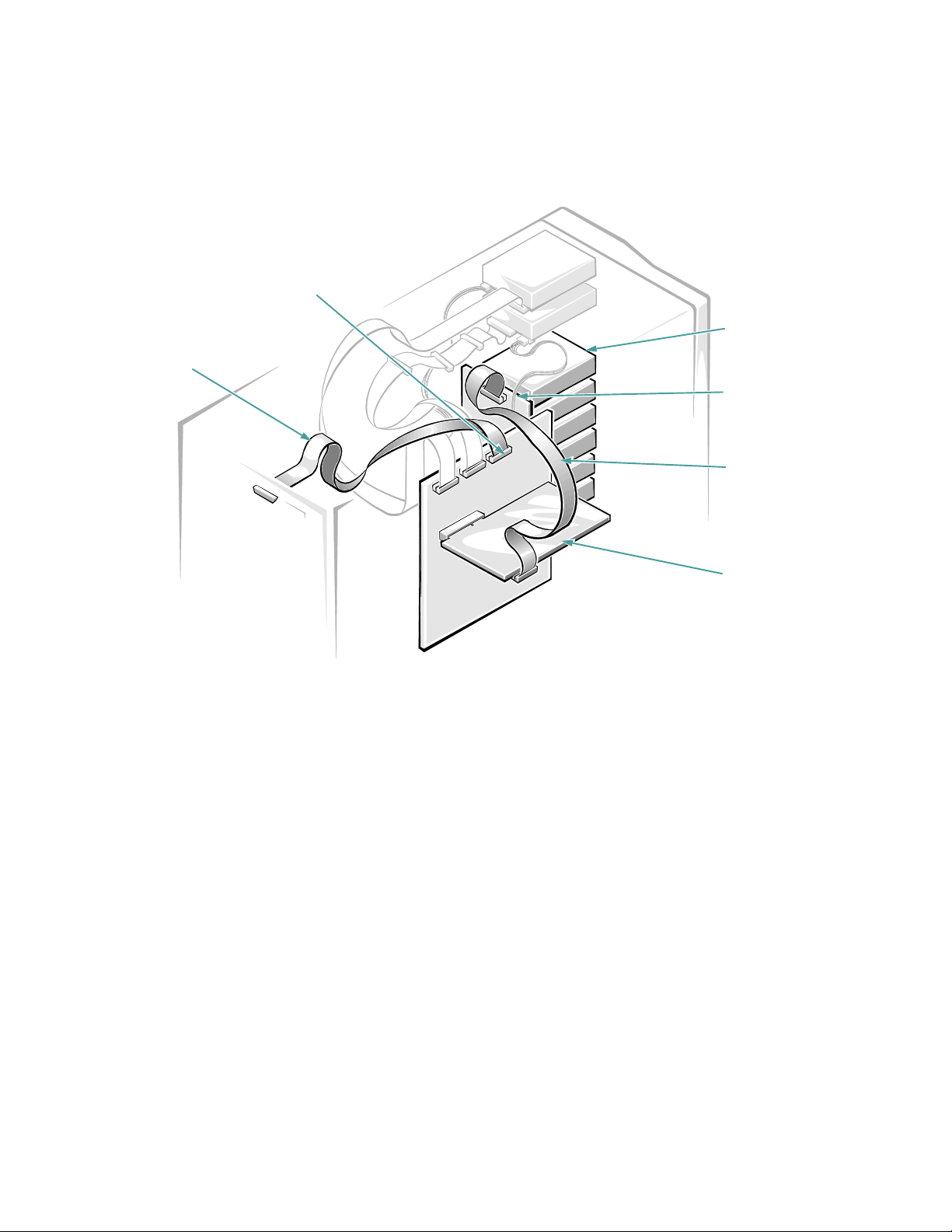
Ultra/Wide SCSI host
adapter
connector (SCSI
BACKPLANE)
SCSI hard-disk
SCSI external
access cable
drive bays (6)
SCSI backplane
board
Ultra/Wide SCSI
interface cable to
SCSI backplane
PowerEdge
Expandable RAID
Controller host
adapter card
Figure 10-3. Cable Configuration for a PowerEdge Expandable RAID Controller Host Adapter Card
10-6 Dell PowerEdge 4100/180 and 4100/200 Systems Installation and Troubleshooting Guide
Page 98
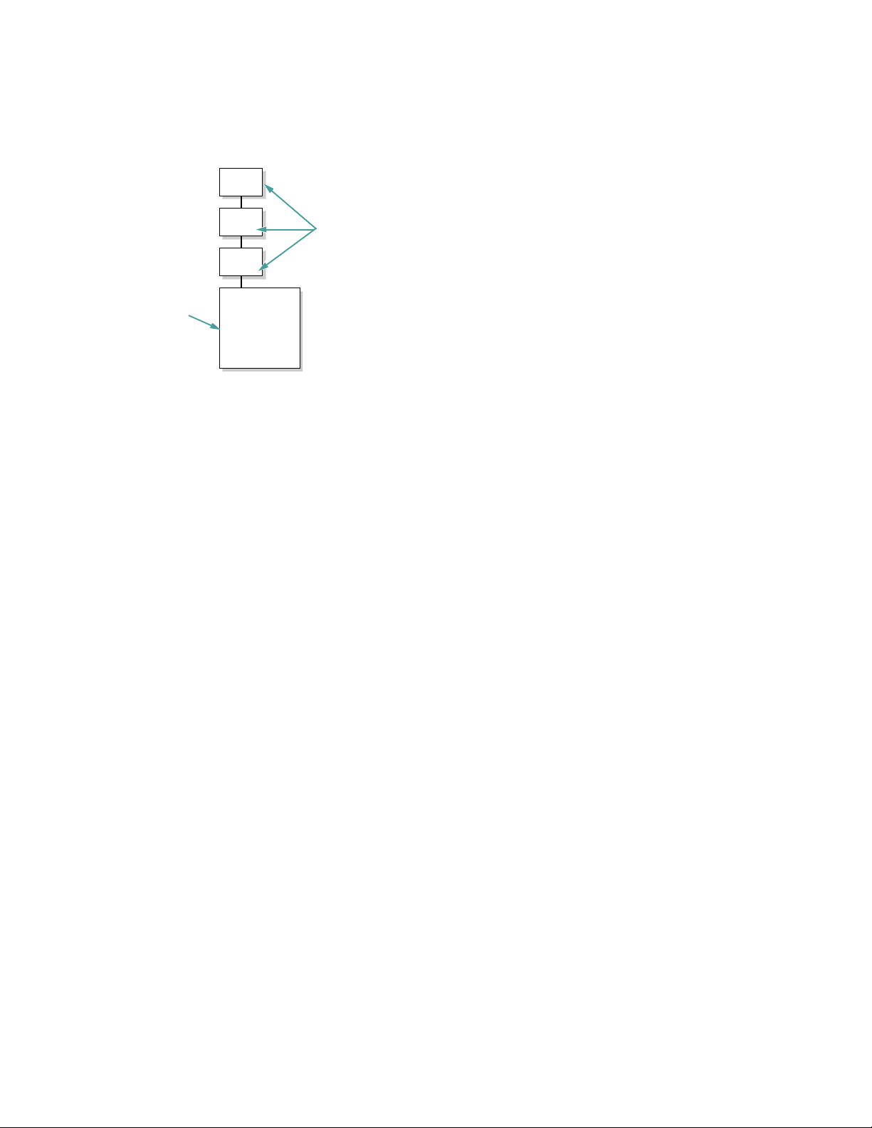
exter na l SCSI
devices
computer
Figure 10-4. Daisy-Chaining External SCSI
Devices
9. Replace the computer cover, and reconnect the
computer and peripherals to their power sources.
10. Connect the external device(s) to power.
For each external device, plug the socket end of the
power cable into the alternating current (AC) power
receptacle on the back of the device. Plug the other
end of the power cable into an AC power source.
11. Install any required SCSI device drivers.
See Chapter 3, “Installing and Configuring SCSI
Drivers,” in the system User’s Guide for informa-
tion and instructions.
12. Test the SCSI devices.
Test a SCSI hard-disk drive by running the SCSI
Devices Test Group in the system diagnostics. See
Chapter 5, “Running the System Diagnostics,” for
information.
To test a SCSI tape drive, also refer to the documentation for the tape drive software to perform a tape
drive backup and verification test.
C
onfiguring the Boot Device
If the user plans to boot the system from a hard-disk
drive, the drive must be attached to the primary (or boot)
controller or SCSI host adapter card. The primary controller is automatically determined by the specific system
configuration according to the following general
guidelines:
•
•
PCI SCAN SEQUENCE
If the
Setup program is set to
in Ultra/Wide host adapter is the primary controller.
PCI SCAN SEQUENCE
If the
Setup program is set to
system boots from a SCSI host adapter card in an
expansion slot. If more than one SCSI host adapter
card is installed, the boot order is determined by the
particular expansion slot the card is installed in. In
descending order of precedence, the boot order for
the Dell PowerEdge 4100 system is PC15, PCI4,
PCI8, PCI7, and PCI6.
category in the System
EMBEDDED FIRST
category in the System
SLOT DEVICES FIRST
, the built-
, the
Partitioning and Formatting SCSI
Hard-Disk Drives
You may need to use different programs than those provided with the operating system to partition and format
SCSI hard-disk drives. See Chapter 3, “Installing and
Configuring SCSI Drivers,” in the system User’s Guide
for information and instructions.
Installing Drives in the Internal Bays 10-7
Page 99

10-8 Dell PowerEdge 4100/180 and 4100/200 Systems Installation and Troubleshooting Guide
Page 100

Chapter 11
Getting Help
T
his chapter describes the tools Dell provides to help
you when you have a problem with a computer system. It
also tells you when and how to call Dell Computer Corporation for technical or customer assistance in the
following situations:
•
If you have a technical problem, read the next sec-
tion, “Technical Assistance.”
•
If you are looking for information about a specific
subject or about Dell’s services, read “Help Tools”
found later in this chapter.
•
If you have a problem with an order, read “Problems
With an Order” found later in this chapter.
•
If you need to return an item for warranty repair or
credit, read “Returning Items for Warranty Repair or
Credit” found later in this chapter.
•
If you would like to place an order or need information about additional products available from Dell,
call Dell at the appropriate telephone number listed
in “Dell Contact Numbers” found later in this
chapter.
T
echnical Assistance
If you need assistance with a technical problem, perform
the following steps:
1. Review the documentation that accompanied the
Dell system.
To decide which document has the answers you
need, consult the Preface of the system
documentation.
2. Run the diagnostics for the Dell system.
See Chapter 5, “Running the System Diagnostics,”
for instructions on using the system diagnostics.
3. Make a copy of the Diagnostics Checklist (found
in Appendix A), and fill it out.
NOTE: Save the Diagnostics Checklist in Appendix A as a master so you can use it to make copies as
needed.
On the Diagnostics Checklist, document any error
messages or beep codes as they occur so you can
inform the Dell technician of them. Describe what
you were doing when the error occurred. Note the
steps you have taken to solve the problem.
4. Use the AutoTech service for help with installation and troubleshooting procedures.
For instructions on using the AutoTech service, see
“AutoTech Service” found later in this chapter.
5. If the preceding steps have not resolved the problem and you need to talk to a Dell technician, you
can call Dell’s customer technical support service.
For instructions on using the technical support service, see “Technical Support Service” found later in
this chapter.
H
elp Tools
Dell provides a number of tools to assist you. Table 11-1
lists subjects you may want information about, tasks you
Getting Help 11-1
 Loading...