

Page 1

Dell Vostro 3560
Owner's Manual
Regulatory Model: P24F
Regulatory Type: P24F001
Page 2

Notes, Cautions, and Warnings
NOTE: A NOTE indicates important information that helps you make better use of your computer.
CAUTION: A CAUTION indicates either potential damage to hardware or loss of data and tells you how to avoid the
problem.
WARNING: A WARNING indicates a potential for property damage, personal injury, or death.
© 2012 Dell Inc.
Trademarks used in this text: Dell™, the Dell logo, Dell Precision™ , OptiPlex™, Latitude™, PowerEdge™, PowerVault™,
PowerConnect™, OpenManage™, EqualLogic™, Compellent™, KACE™, FlexAddress™, Force10™ and Vostro™ are trademarks of Dell
Inc. Intel®, Pentium®, Xeon®, Core® and Celeron® are registered trademarks of Intel Corporation in the U.S. and other countries. AMD
is a registered trademark and AMD Opteron™, AMD Phenom™ and AMD Sempron™ are trademarks of Advanced Micro Devices, Inc.
Microsoft®, Windows®, Windows Server®, Internet Explorer®, MS-DOS®, Windows Vista® and Active Directory® are either trademarks
or registered trademarks of Microsoft Corporation in the United States and/or other countries. Red Hat® and Red Hat
Enterprise Linux® are registered trademarks of Red Hat, Inc. in the United States and/or other countries. Novell® and SUSE® are
registered trademarks of Novell Inc. in the United States and other countries. Oracle® is a registered trademark of Oracle Corporation
and/or its affiliates. Citrix®, Xen®, XenServer® and XenMotion® are either registered trademarks or trademarks of Citrix Systems, Inc. in
the United States and/or other countries. VMware
trademarks of VMware, Inc. in the United States or other countries.
Corporation.
2012 - 06
®
,
Virtual SMP
®
®
,
vMotion
®
is a registered trademark of International Business Machines
IBM
,
vCenter
®
and
vSphere
®
are registered trademarks or
®
®
Rev. A00
Page 3

Contents
Notes, Cautions, and Warnings...................................................................................................2
1 Working on Your Computer.......................................................................................................5
Before Working Inside Your Computer.....................................................................................................................5
Recommended Tools................................................................................................................................................6
Turning Off Your Computer.......................................................................................................................................6
After Working Inside Your Computer........................................................................................................................7
2 Removing and Installing Components.....................................................................................9
Removing the Security Digital (SD) Card..................................................................................................................9
Installing the Secure Digital Card.............................................................................................................................9
Removing the Battery...............................................................................................................................................9
Installing the Battery..............................................................................................................................................10
Removing the ExpressCard.....................................................................................................................................10
Installing the ExpressCard......................................................................................................................................10
Removing the Base Cover.......................................................................................................................................10
Installing the Base Cover........................................................................................................................................12
Removing the Memory............................................................................................................................................12
Installing the Memory.............................................................................................................................................12
Removing the Optical Drive....................................................................................................................................12
Installing the Optical Drive.....................................................................................................................................14
Removing the Hard Drive........................................................................................................................................14
Installing the Hard Drive.........................................................................................................................................16
Removing the Keyboard..........................................................................................................................................16
Installing the Keyboard...........................................................................................................................................18
Removing the Display Hinge Cover.........................................................................................................................18
Installing the Display Hinge Cover..........................................................................................................................19
Removing the Palmrest...........................................................................................................................................19
Installing the Palmrest............................................................................................................................................24
Removing the ExpressCard Reader........................................................................................................................24
Installing the Express Card Reader........................................................................................................................26
Removing the Speakers..........................................................................................................................................26
Installing the Speakers...........................................................................................................................................28
Removing the System Board...................................................................................................................................28
Installing the System Board....................................................................................................................................32
Removing the Heat Sink..........................................................................................................................................32
Installing the Heat Sink...........................................................................................................................................34
Page 4

Removing the Processor.........................................................................................................................................34
Installing the Processor..........................................................................................................................................35
Removing the Coin-Cell Battery..............................................................................................................................35
Installing the Coin-Cell Battery...............................................................................................................................36
Removing the Wireless Local Area Network (WLAN) Card...................................................................................36
Installing the Wireless Local Area Network (WLAN) Card....................................................................................36
Removing the LAN Board.......................................................................................................................................37
Installing the LAN Board.........................................................................................................................................38
Removing the mini-SATA Card...............................................................................................................................39
Installing the mini-SATA Card.................................................................................................................................39
Removing the Secure Digital (SD) Card Reader.....................................................................................................40
Installing the Secure Digital (SD) Card Reader......................................................................................................41
Removing the Display Assembly.............................................................................................................................41
Installing the Display Assembly..............................................................................................................................43
Removing the Power Connector.............................................................................................................................44
Installing the Power Connector..............................................................................................................................44
Removing the Display Bezel...................................................................................................................................45
Installing the Display Bezel.....................................................................................................................................46
Removing the Display Bracket................................................................................................................................47
Installing the Display Bracket.................................................................................................................................49
Removing the Camera Module...............................................................................................................................50
Installing the Camera Module.................................................................................................................................50
3 System Setup.............................................................................................................................53
Boot Sequence.......................................................................................................................................................53
Navigation Keys......................................................................................................................................................53
System Setup Options.............................................................................................................................................54
Updating the BIOS .................................................................................................................................................58
System and Setup Password..................................................................................................................................58
Assigning a System Password and Setup Password......................................................................................58
Deleting or Changing an Existing System and/or Setup Password..................................................................59
4 Diagnostics.................................................................................................................................61
Enhanced Pre-Boot System Assessment (ePSA) Diagnostics...............................................................................61
Device Status Lights...............................................................................................................................................61
Battery Status Lights..............................................................................................................................................62
Diagnostic Beep Codes..........................................................................................................................................62
5 Specifications............................................................................................................................65
6 Getting Help................................................................................................................................71
Contacting Dell.......................................................................................................................................................71
Page 5
Working on Your Computer
Before Working Inside Your Computer
Use the following safety guidelines to help protect your computer from potential damage and to help to ensure your
personal safety. Unless otherwise noted, each procedure included in this document assumes that the following
conditions exist:
• You have performed the steps in Working on Your Computer.
• You have read the safety information that shipped with your computer.
• A component can be replaced or--if purchased separately--installed by performing the removal procedure in
reverse order.
WARNING: Before working inside your computer, read the safety information that shipped with your computer. For
additional safety best practices information, see the Regulatory Compliance Homepage at www.dell.com/
regulatory_compliance
CAUTION: Many repairs may only be done by a certified service technician. You should only perform
troubleshooting and simple repairs as authorized in your product documentation, or as directed by the online or
telephone service and support team. Damage due to servicing that is not authorized by Dell is not covered by your
warranty. Read and follow the safety instructions that came with the product.
CAUTION: To avoid electrostatic discharge, ground yourself by using a wrist grounding strap or by periodically
touching an unpainted metal surface, such as a connector on the back of the computer.
1
CAUTION: Handle components and cards with care. Do not touch the components or contacts on a card. Hold a
card by its edges or by its metal mounting bracket. Hold a component such as a processor by its edges, not by its
pins.
CAUTION: When you disconnect a cable, pull on its connector or on its pull-tab, not on the cable itself. Some
cables have connectors with locking tabs; if you are disconnecting this type of cable, press in on the locking tabs
before you disconnect the cable. As you pull connectors apart, keep them evenly aligned to avoid bending any
connector pins. Also, before you connect a cable, ensure that both connectors are correctly oriented and aligned.
NOTE: The color of your computer and certain components may appear differently than shown in this document.
To avoid damaging your computer, perform the following steps before you begin working inside the computer.
1. Ensure that your work surface is flat and clean to prevent the computer cover from being scratched.
2. Turn off your computer (see Turning Off Your Computer).
3. If the computer is connected to a docking device (docked) such as the optional Media Base or Battery Slice,
undock it.
CAUTION: To disconnect a network cable, first unplug the cable from your computer and then unplug the cable
from the network device.
4. Disconnect all network cables from the computer.
5. Disconnect your computer and all attached devices from their electrical outlets.
5
Page 6
6. Close the display and turn the computer upside-down on a flat work surface.
NOTE: To avoid damaging the system board, you must remove the main battery before you service the computer.
7. Remove the main battery.
8. Turn the computer top-side up.
9. Open the display.
10. Press the power button to ground the system board.
CAUTION: To guard against electrical shock, always unplug your computer from the electrical outlet before
opening the display.
CAUTION: Before touching anything inside your computer, ground yourself by touching an unpainted metal
surface, such as the metal at the back of the computer. While you work, periodically touch an unpainted metal
surface to dissipate static electricity, which could harm internal components.
11. Remove any installed ExpressCards or Smart Cards from the appropriate slots.
Recommended Tools
The procedures in this document may require the following tools:
• Small flat-blade screwdriver
• #0 Phillips screwdriver
• #1 Phillips screwdriver
• Small plastic scribe
• Flash BIOS update program CD
Turning Off Your Computer
CAUTION: To avoid losing data, save and close all open files and exit all open programs before you turn off your
computer.
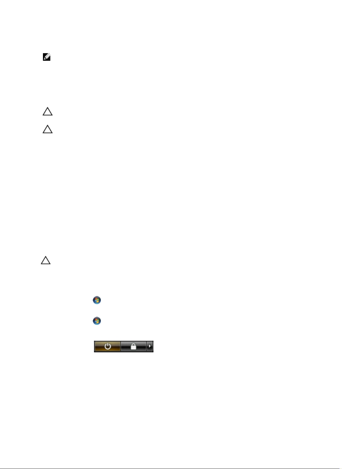
1. Shut down the operating system:
– In Windows 7:
Click Start , then click Shut Down.
– In Windows Vista :
Click Start , then click the arrow in the lower-right corner of the Start menu as shown below, and then
click Shut Down.
– In Windows XP:
Click Start → Turn Off Computer → Turn Off . The computer turns off after the operating system shutdown
process is complete.
2. Ensure that the computer and all attached devices are turned off. If your computer and attached devices did not
automatically turn off when you shut down your operating system, press and hold the power button for about 4
seconds to turn them off.
6
Page 7

After Working Inside Your Computer
After you complete any replacement procedure, ensure you connect any external devices, cards, and cables before
turning on your computer.
CAUTION: To avoid damage to the computer, use only the battery designed for this particular Dell computer. Do not
use batteries designed for other Dell computers.
1. Connect any external devices, such as a port replicator, battery slice, or media base, and replace any cards, such
as an ExpressCard.
2. Connect any telephone or network cables to your computer.
CAUTION: To connect a network cable, first plug the cable into the network device and then plug it into the
computer.
3. Replace the battery.
4. Connect your computer and all attached devices to their electrical outlets.
5. Turn on your computer.
7
Page 8

8
Page 9
Removing and Installing Components
This section provides detailed information on how to remove or install the components from your computer.
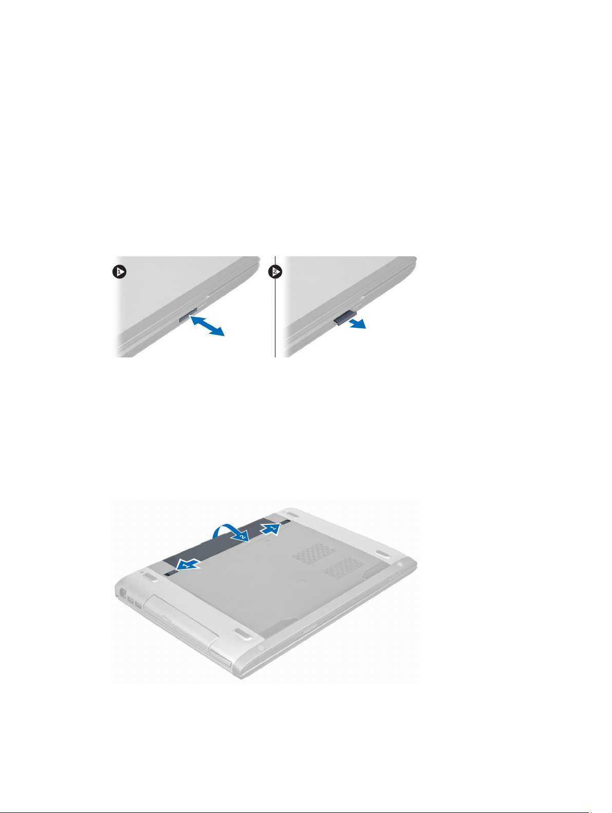
Removing the Security Digital (SD) Card
2
1. Follow the procedures in
2. Press in on the SD card to release it from the computer. Slide the SD card out of the computer.
Before Working Inside Your Computer
.
Installing the Secure Digital Card
1. Push the SD card into the slot until it clicks into place.
2. Follow the procedures in
After Working Inside Your Computer
.
Removing the Battery
1. Follow the procedures in
2. Slide the battery latches to release the battery.
Before Working On Your Computer
.
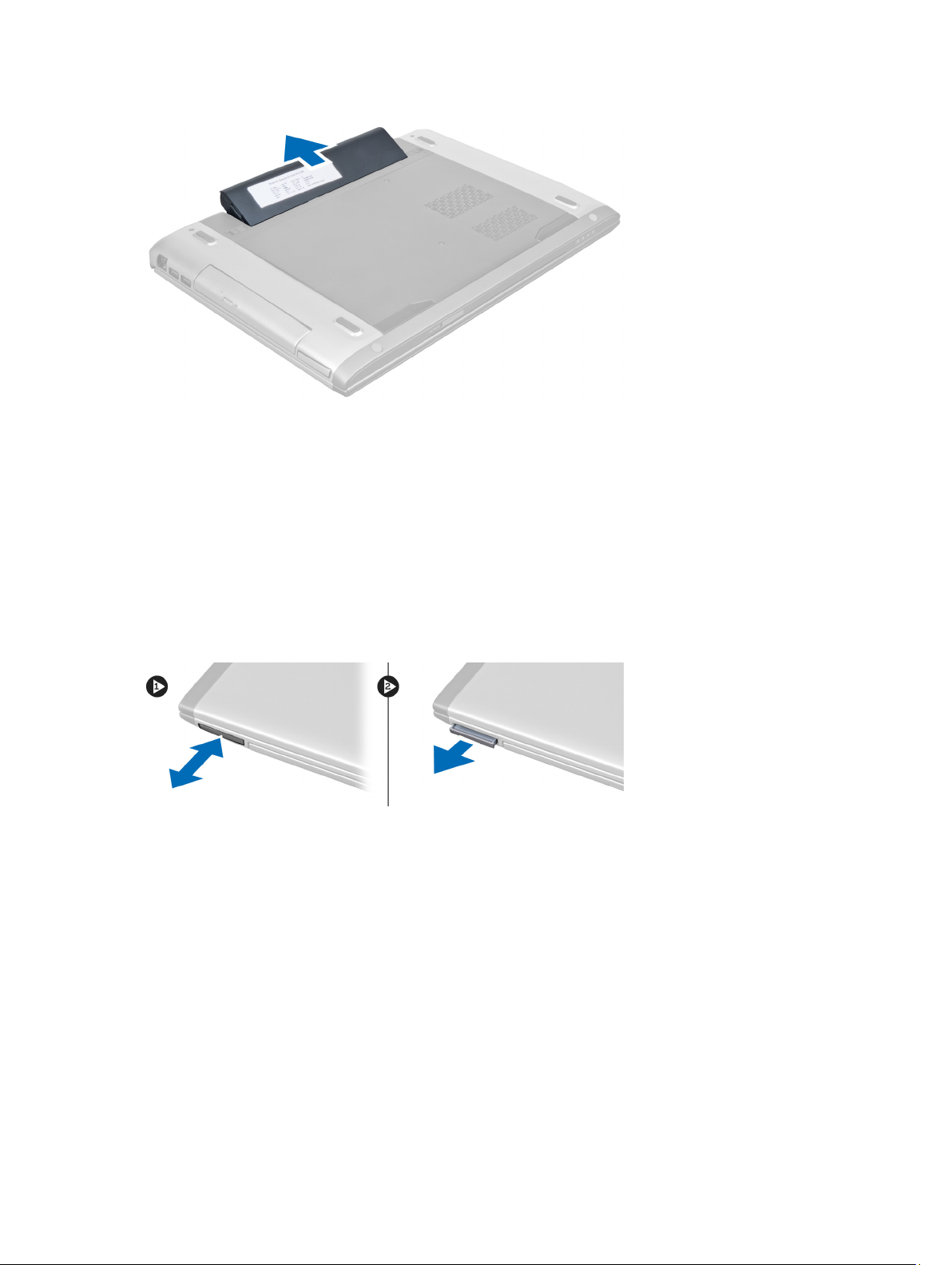
3. Lift and remove the battery from the computer.
9
Page 10
Installing the Battery
1. Slide the battery into its slot until it clicks into place.
2. Follow the procedures in
After Working Inside Your Computer.
Removing the ExpressCard
1. Follow the procedures in
2. Remove the battery.
3. Press in on the ExpressCard and release. Pull the ExpressCard and remove out of the computer.
Before Working Inside Your Computer
.
Installing the ExpressCard
1. Push in the ExpressCard into the slot until it clicks into place.
2. Install the battery.
3. Follow the procedures in
After Working Inside Your Computer
.
Removing the Base Cover
1. Follow the procedures in
2. Remove the battery.
3. Remove the screw(s) that secures the cover to the computer. Lift the cover upwards.
10
Before Working Inside Your Computer
.
Page 11
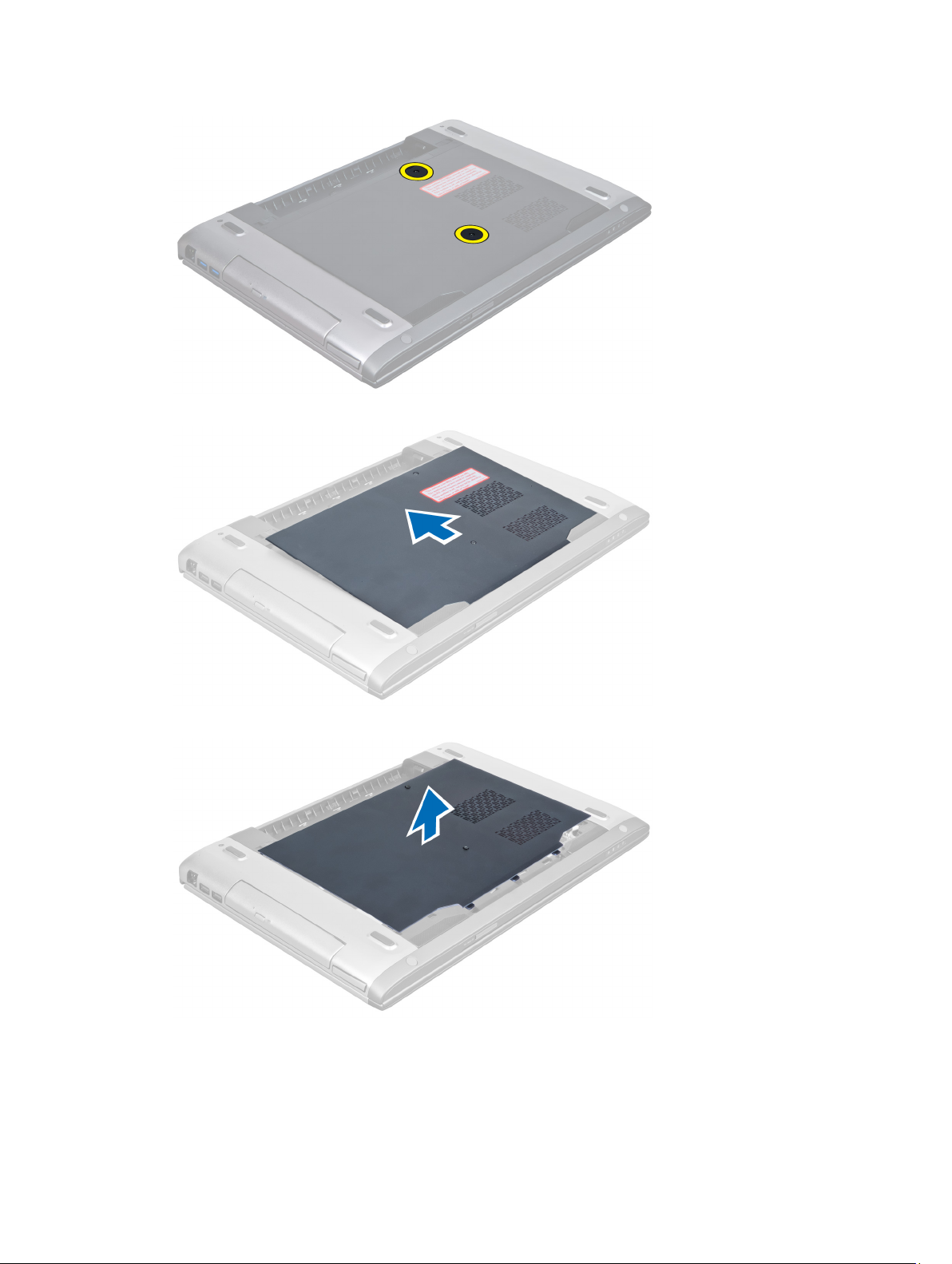
4. Slide the cover outwards to release it from the notches on the computer.
5. Lift the cover upwards and away from the computer.
11
Page 12
Installing the Base Cover
1. Align the edge of the base cover on the computer and slide it on the computer.
2. Tighten the screw(s) to secure the base cover to the computer.
3. Install the battery.
4. Follow the procedures in
After Working Inside Your Computer.
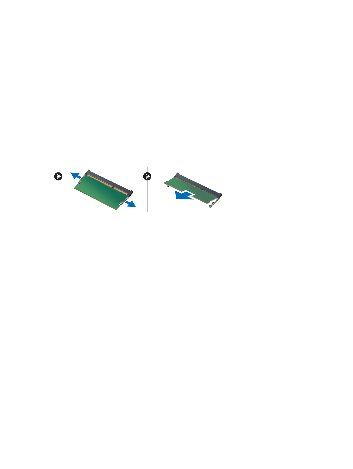
Removing the Memory
1. Follow the procedures in
2. Remove the:
a) battery
b) base cover
3. Pry the retention clips away from the memory module until it pops-up. Lift and remove the memory module from its
connector.
Before Working Inside Your Computer
.
Installing the Memory
1. Insert and secure the memory module to the system board.
2. Install the:
a) base cover
b) battery
3. Follow the procedures in
After Working Inside Your Computer
.
Removing the Optical Drive
1. Follow the procedures in
2. Remove the:
a) battery
b) base cover
3. Remove the screw that secures the optical drive to the computer.
12
Before Working Inside Your Computer
.
Page 13
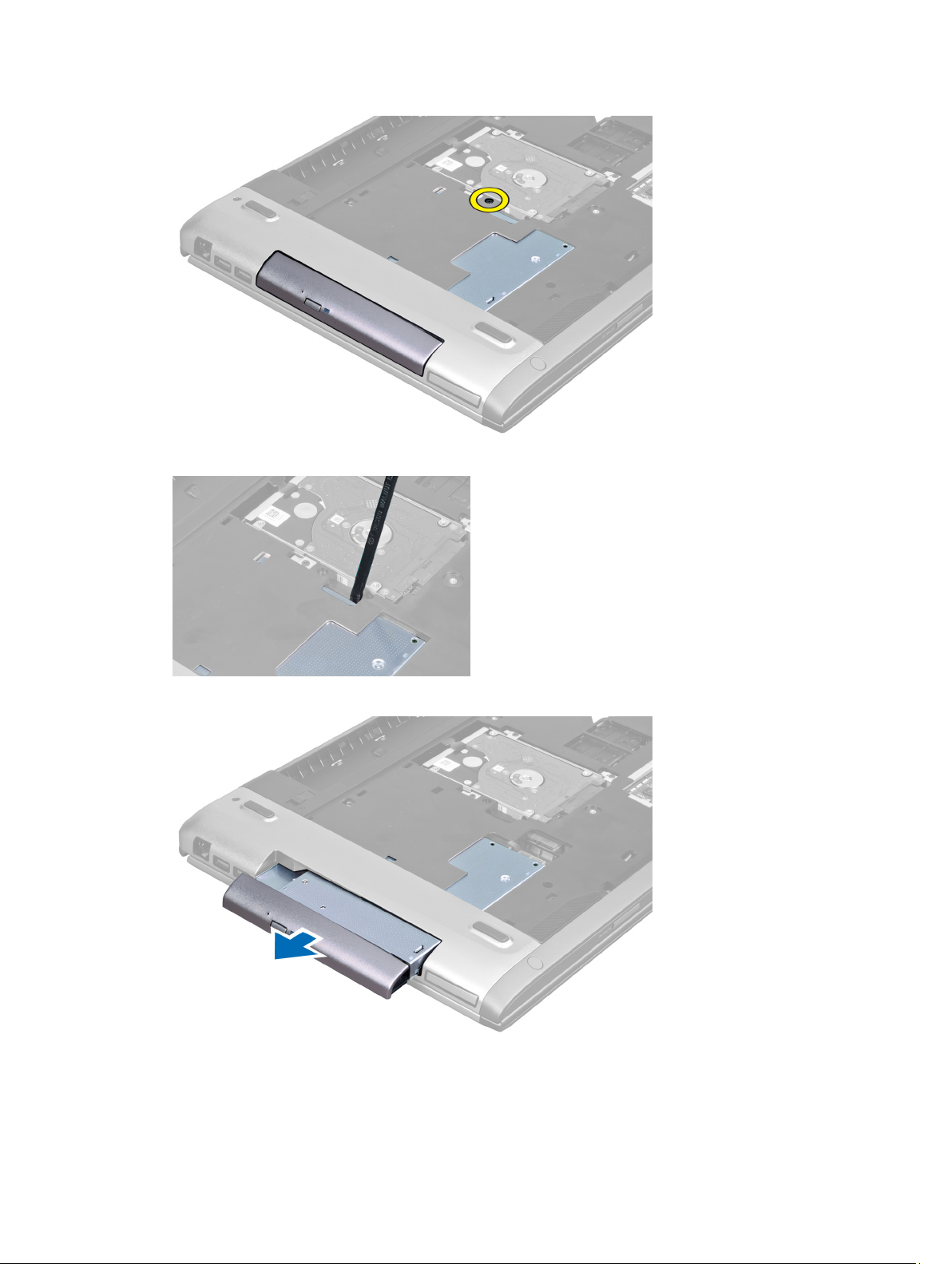
4. Use a flat-headed screw driver to pry the optical drive out of the computer.
5. Slide the optical drive outwards and remove it from the computer.
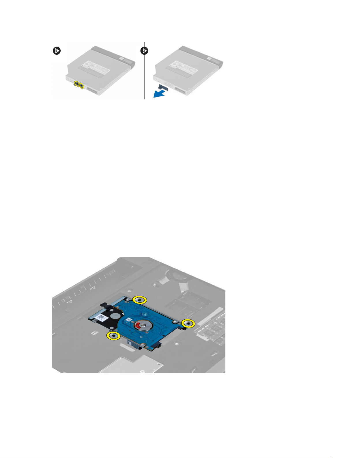
6. Remove the screws that secure the optical-drive bracket. Remove the optical-drive bracket from the optical drive.
13
Page 14
Installing the Optical Drive
1. Replace the optical-drive bracket and tighten the screws that secure the optical drive to the optical-drive bracket.
2. Slide the optical drive into the compartment on the chassis.
3. Tighten the screw to secure the optical drive to the computer.
4. Install the:
a) base cover
b) battery
5. Follow the procedures in
After Working Inside Your Computer.
Removing the Hard Drive
1. Follow the procedures in
2. Remove the:
a) battery
b) base cover
3. Remove the screws that secure the hard drive to the computer.
Before Working Inside Your Computer
.
4. Pull the tab to release the hard drive from the hard drive connector.
14
Page 15
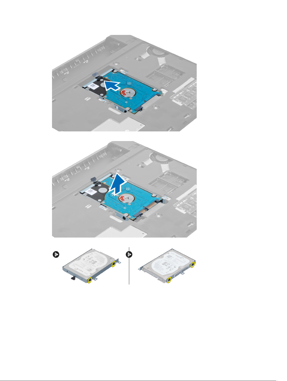
5. Lift up the hard drive and remove from the computer.
6. Remove the screws that secure the hard-drive bracket to the hard drive.
7. Lift up and remove the hard drive from the hard drive bracket.
15
Page 16
Installing the Hard Drive
1. Place the hard drive module into the hard drive bracket.
2. Tighten the screws that secures the hard drive bracket to the hard drive.
3. Pull the tab and place the hard drive on the chassis.
4. Tighten the screws that secure hard drive to the computer.
5. Install the:
a) battery
b) base cover
6. Follow the procedures in
After Working Inside Your Computer
.
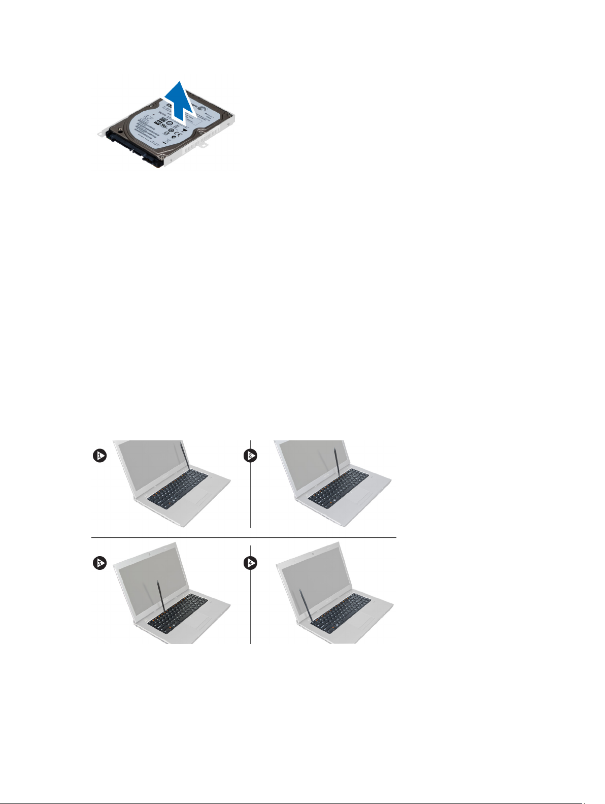
Removing the Keyboard
1. Follow the procedures in
2. Remove the battery.
3. Using of a flat-head screwdriver release the latches that secures the keyboard to the computer.
Before Working Inside Your Computer
.
4. Flip the keyboard over and lay it on the palmrest.
16
Page 17
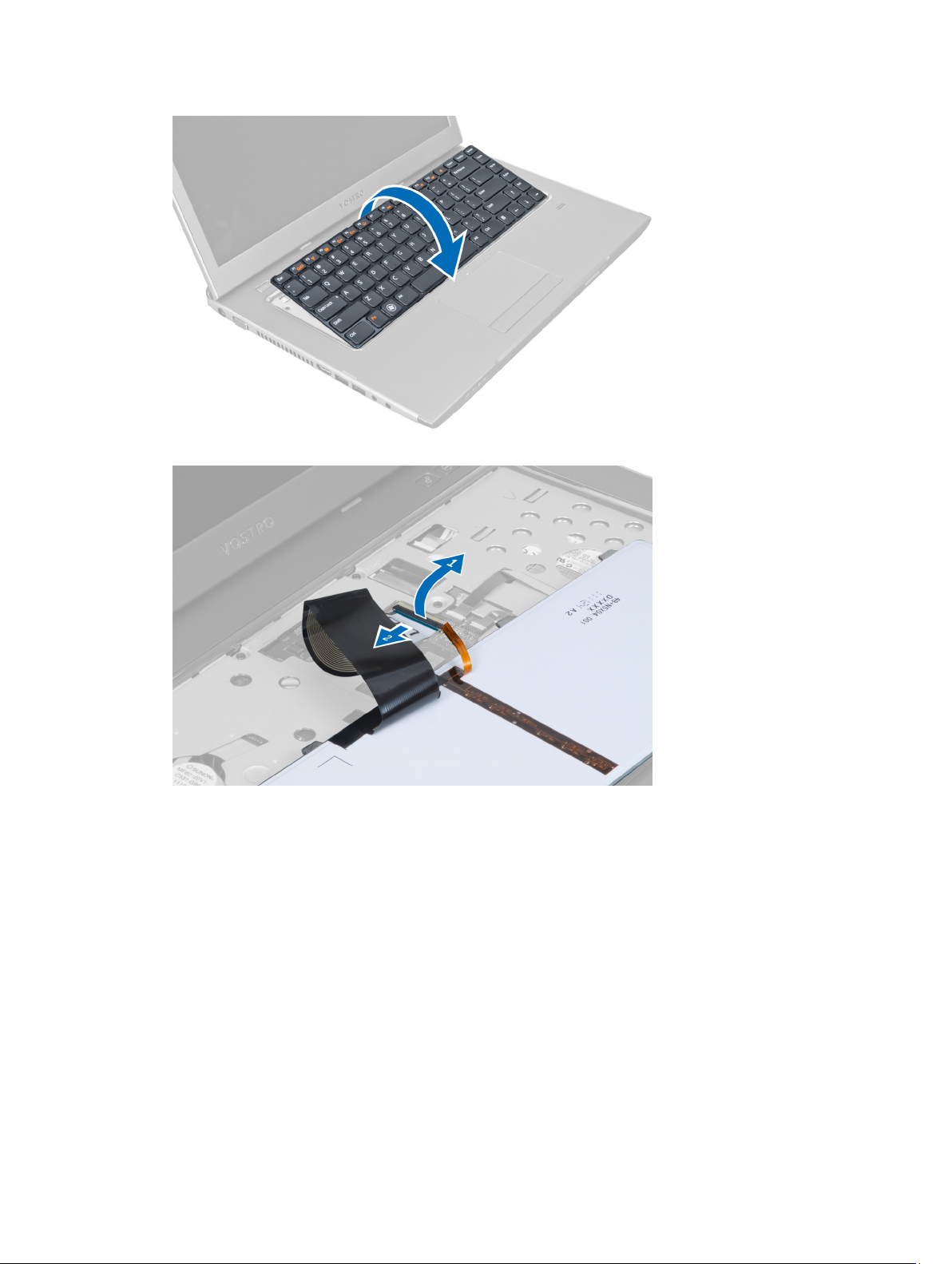
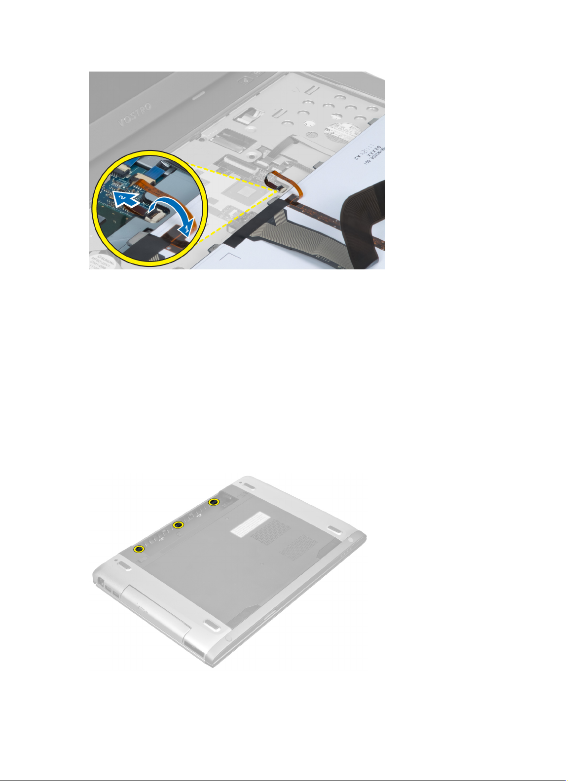
5. Lift the clip to release the keyboard cable and disconnect it from the system board.
6. Lift the clip to release the backlit cable and disconnect it from the system board.
17
Page 18
Installing the Keyboard
1. Connect the keyboard data cable to the back of the keyboard.
2. Connect the backlit cable to the system board.
3. Insert the keyboard in its compartment.
4. Press down until the keyboard clicks into place.
5. Install the battery.
6. Follow the procedures in
After Working Inside Your Computer
Removing the Display Hinge Cover
.
1. Follow the procedures in
2. Remove the battery.
3. Remove the screws that secure the display-hinge cover to the computer.
18
Before Working On Your Computer
.
Page 19
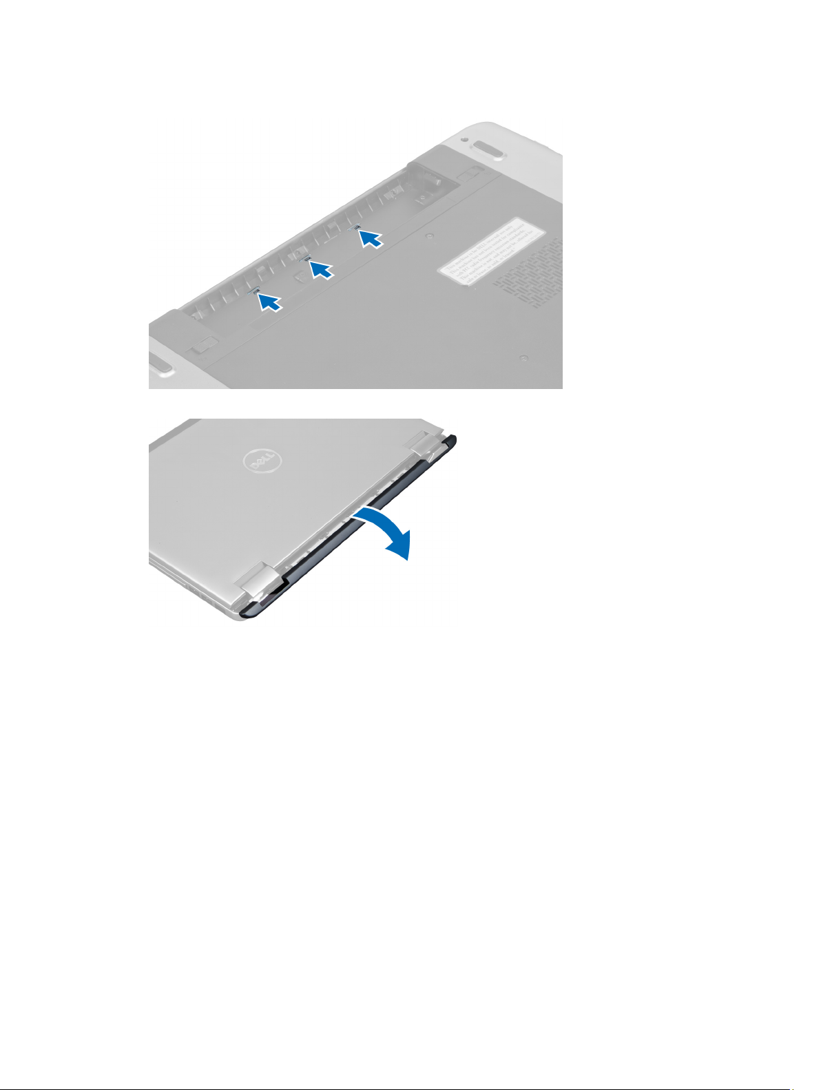
4. Push to release the hinge cover from the computer.
5. Flip the computer and carefully remove the display hinge cover from the computer.
Installing the Display Hinge Cover
1. Replace the display hinge cover back to the computer till the latches are fixed into place.
2. Tighten the screws that secure the display hinge cover to the computer.
3. Install the battery.
4. Follow the procedures in
After Working Inside Your Computer
.
Removing the Palmrest
1. Follow the procedures in
2. Remove the:
a) battery
b) base cover
c) memory
d) optical drive
e) hard drive
Before Working Inside Your Computer
.
19
Page 20
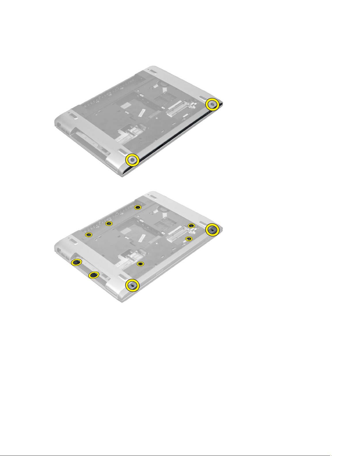
f) keyboard
g) display hinge cover
3. Remove the rubber pads from the bottom of the computer.
4. Remove the screws from the bottom of the computer.
5. Disconnect the LEDs fingerprint cable.
20
Page 21
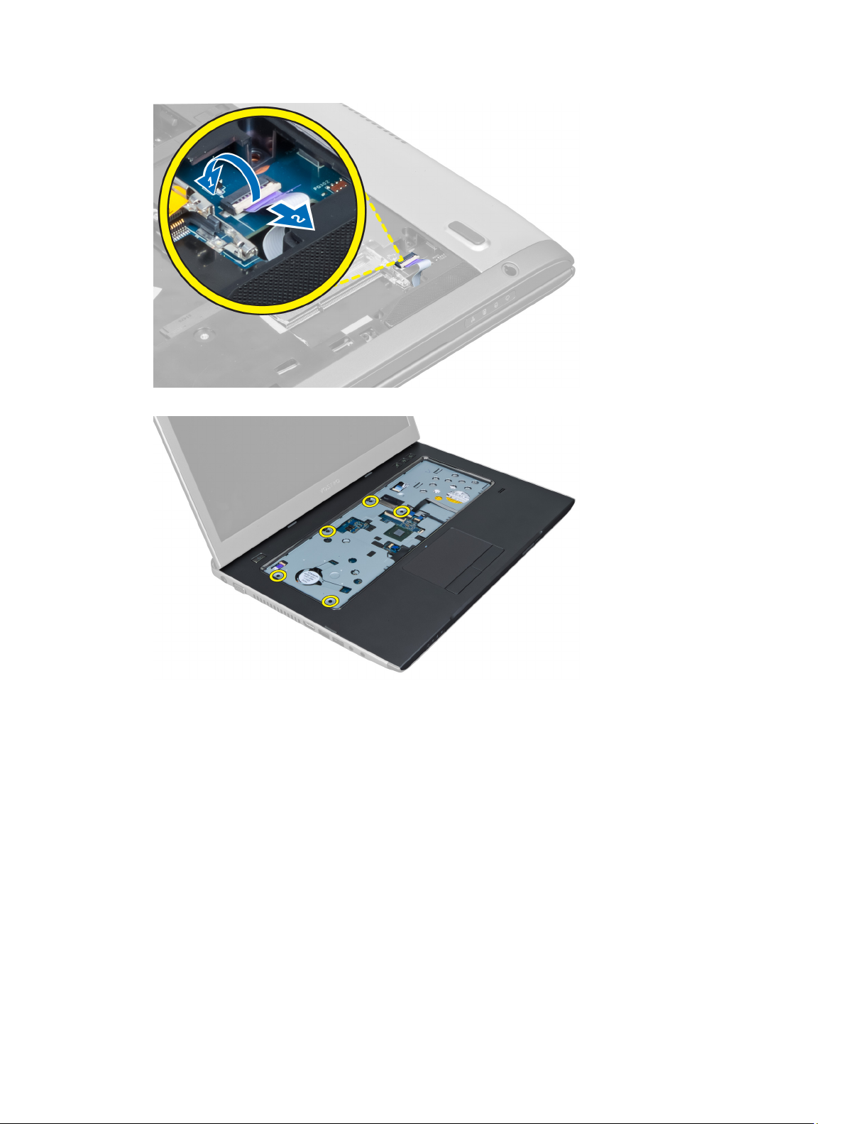
6. Remove the screws that secures palmrest assembly in place.
7. Lift the latch and disconnect the power button fingerprint cable.
21
Page 22
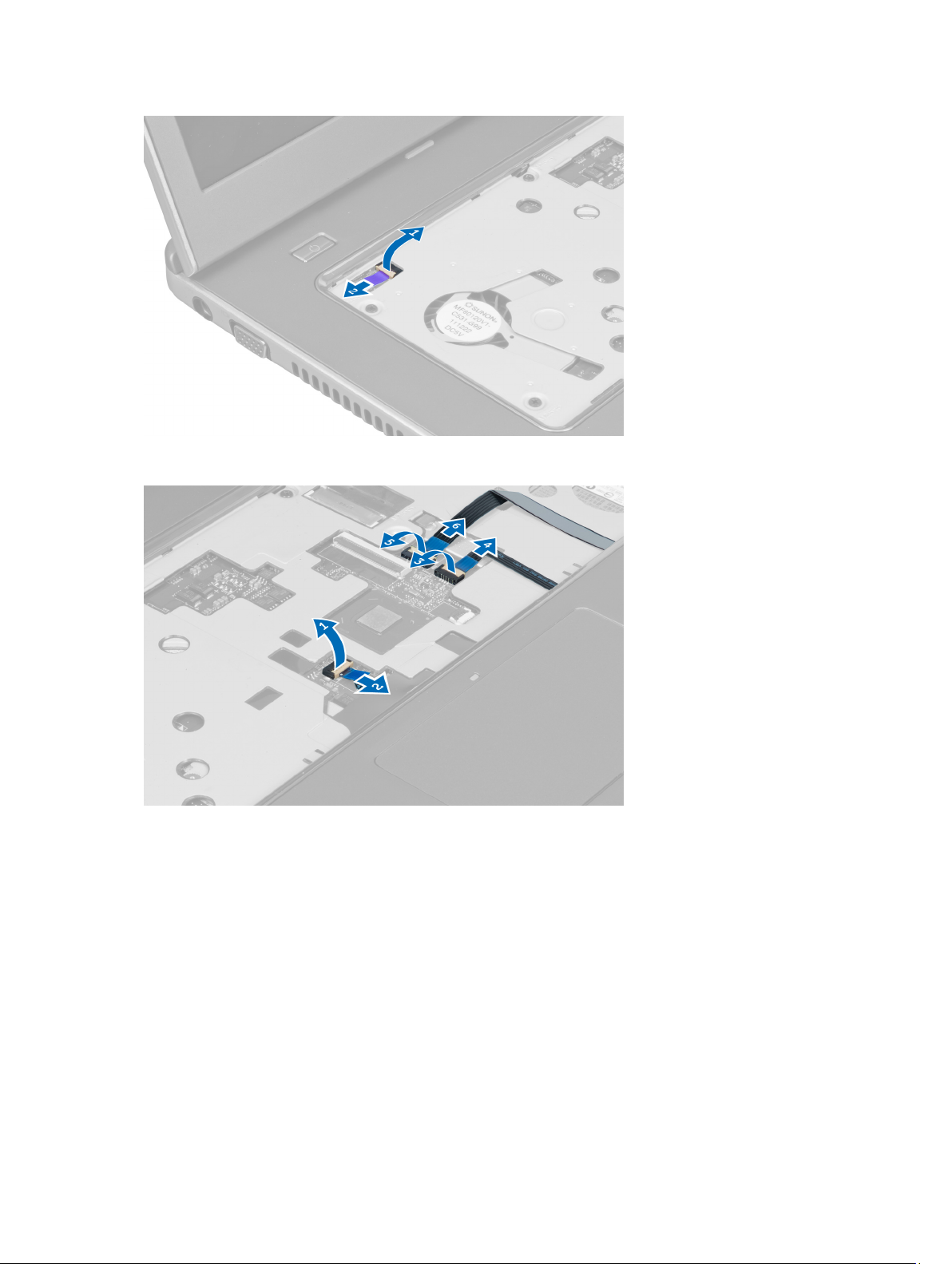
8. Lift the tab and release the touchpad cable, SD card reader cable, and fingerprint scanner cable from the
computer.
9. Lift the tab and disconnect the functions button cable from the system.
22
Page 23

10. Carefully pry up the palmrest along the edges.
11. Slide the palmrest outwards and lift to remove from the computer.
23
Page 24

Installing the Palmrest
1. Starting from the edges of the palmrest, press downwards on the palmrest to engage the tabs on the computer.
2. Tighten the screws to secure the palmrest to the front of the computer.
3. Connect the functions button cable to the system board.
4. Connect the touchpad cable, SD card reader cable, and fingerprint scanner cable to the system board.
5. Connect the power button fingerprint cable to the system board.
6. Tighten the screws to secure the palmrest to the back of the computer.
7. Connect the LEDs fingerprint cable to the system board.
8. Tighten the screws on the bottom of the computer that secure the palmrest in place.
9. Push the rubber pads to cover the screws on the computer.
10. Install the:
a) display hinge cover
b) keyboard
c) hard drive
d) optical drive
e) memory
f) base cover
g) battery
11. Follow the procedures in
After Working Inside Your Computer
.
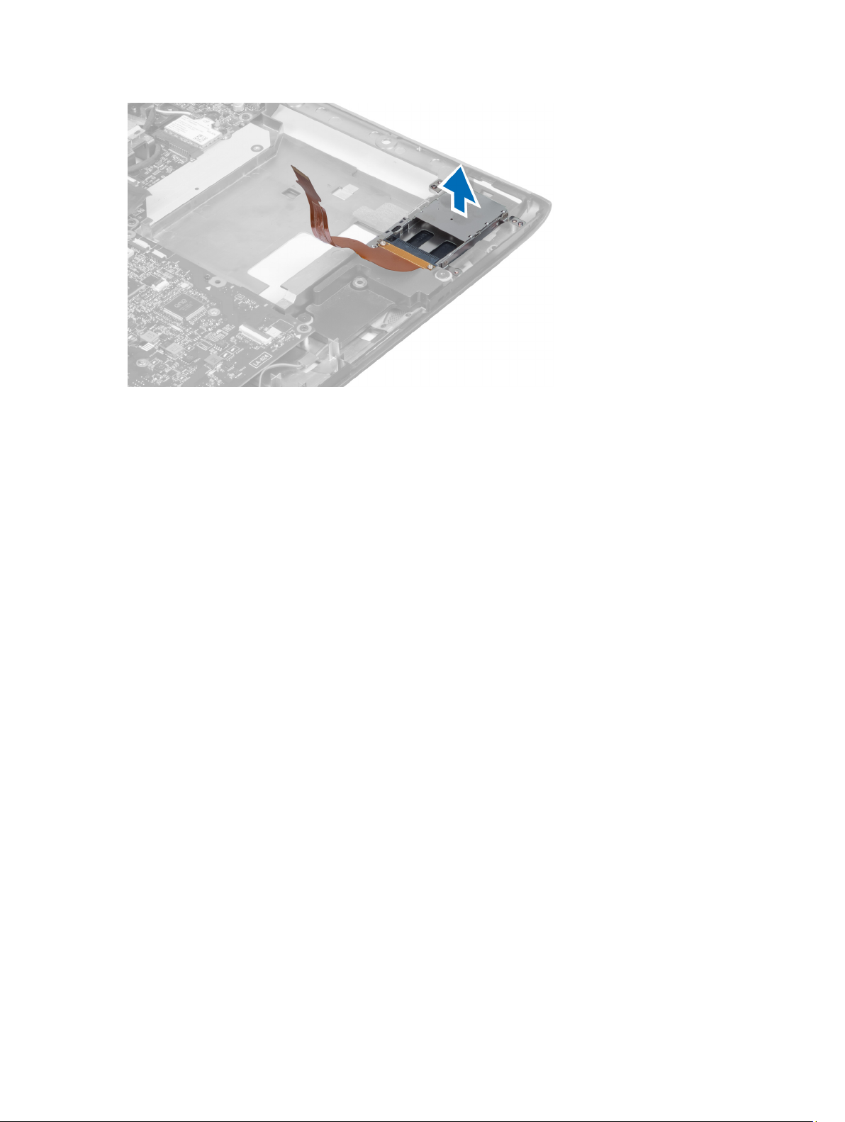
Removing the ExpressCard Reader
1. Follow the procedures in
2. Remove the:
a) SD Card
b) express card
c) battery
d) base cover
e) keyboard
24
Before Working Inside Your Computer
.
Page 25

f) display hinge cover
g) palmrest
3. Lift the tab and disconnect the express card reader cable.
4. Remove the screws that secure the express card reader in place.
5. Lift up and remove the express card reader from the system.
25
Page 26
Installing the Express Card Reader
1. Place the express card reader into its slot on the chassis.
2. Tighten the screws to secure the express card reader to the computer.
3. Connect the express card reader cable.
4. Install the:
a) palmrest
b) display hinge cover
c) keyboard
d) base cover
e) battery
f) express card
g) SD card
5. Follow the procedures in
After Working Inside Your Computer
.
Removing the Speakers
1. Follow the procedures in
2. Remove the:
a) SD card
b) express card
c) battery
d) base cover
e) optical drive
f) hard drive
g) keyboard
h) display hinge cover
i) palmrest
j) express card reader
3. Disconnect the speaker cable.
26
Before Working Inside Your Computer.
Page 27

4. Remove the screws that secure the speakers in place.
5. Lift up the left speaker and remove.
27
Page 28

Installing the Speakers
1. Place the speakers on the computer and thread the speakers cable through the routing tabs.
2. Tighten the screws to secure the speakers in place.
3. Connect the speaker cable.
4. Install the:
a) express card reader
b) palmrest
c) display hinge cover
d) keyboard
e) hard drive
f) optical drive
g) base cover
h) battery
i) express card
j) SD card
5. Follow the procedures in
After Working Inside Your Computer
.
Removing the System Board
1. Follow the procedures in
2. Remove the:
a) SD Card
b) express card
c) battery
d) base cover
e) optical drive
f) hard drive
g) keyboard
h) display hinge cover
i) palmrest
28
Before Working Inside Your Computer.
Page 29

j) SD card reader
3. Disconnect the system fan cable and the power cable.
4. Disconnect the speaker cable.
5. Disconnect the Express card reader fingerprint cable.
6. Disconnect the touchpad cable.
29
Page 30

7. Peel off the tape and disconnect the LVDS and camera cable.
8. Remove the screws that secure the system board to the chassis.
30
Page 31

9. Lift up the system board from the chassis.
10. Slide the system board towards right and remove from the chassis.
31
Page 32

Installing the System Board
1. Align the system board to the port connectors and place the system board in the computer.
2. Tighten the screws to secure the system board to the chassis.
3. Affix the tape and connect the LVDS and camera cable.
4. Connect the touchpad cable.
5. Connect the express card reader cable.
6. Connect the speaker cable.
7. Connect the system fan cable and the power cable.
8. Install the:
a) SD card reader
b) palmrest
c) display hinge cover
d) keyboard
e) hard drive
f) optical drive
g) base cover
h) battery
i) express card
j) SD card
9. Follow the procedures in
After Working Inside Your Computer
.
Removing the Heat Sink
1. Follow the procedures in
2. Remove the:
a) SD card
b) express card
c) battery
d) base cover
32
Before Working Inside Your Computer.
Page 33

e) memory
f) optical drive
g) hard disk drive
h) keyboard
i) display hinge cover
j) palmrest
k) system board
3. Disconnect the system fan cable from the system board.
4. Remove the screws that secure the heat sink to the system board.
5. Lift up and remove the heat sink from the system board.
33
Page 34

Installing the Heat Sink
1. Tighten the screws to secure the heat sink to the system board.
2. Connect the system fan cable to the system board.
3. Install the:
a) system board
b) palmrest
c) display hinge cover
d) keyboard
e) hard drive
f) optical drive
g) memory
h) base cover
i) battery
j) express card
k) SD card
4. Follow the procedures in
After Working Inside Your Computer
Removing the Processor
.
1. Follow the procedures in
2. Remove the:
a) battery
b) base cover
c) memory
d) optical drive
e) hard drive
f) keyboard
g) palmrest
h) WLAN card
i) ExpressCard reader
34
Before Working Inside Your Computer
.
Page 35

j) speaker
k) system board
l) heat sink
3. Remove the screw. Remove the processor cover and lift the processor from the socket. Place it in an antistatic
package.
Installing the Processor
1. Insert the processor into the processor socket. Ensure the processor is properly seated. Replace the processor
cover.
2. Tighten the screw to secure the processor to the system board.
3. Install the:
a) heat sink
b) system board
c) ExpressCard reader
d) WLAN card
e) palmrest
f) keyboard
g) hard drive
h) optical drive
i) memory
j) base cover
k) battery
4. Follow the procedures in
After Working Inside Your Computer
.
Removing the Coin-Cell Battery
1. Follow the procedures in
2. Remove the:
a) battery
b) base cover
c) memory
d) optical drive
e) hard drive
f) keyboard
g) palmrest
h) ExpressCard reader
i) WLAN card
j) speaker
k) system board
3. Flip the system board and locate the coin-cell battery.
Before Working Inside Your Computer
35
Page 36

4. Use a screw driver to release the coin-cell battery from the socket. The battery pops-out, lift and remove the
battery from the socket.
Installing the Coin-Cell Battery
1. Insert the coin-cell battery into the slot.
2. Press on the coin-cell battery until it secures into place.
3. Install the:
a) system board
b) WLAN card
c) ExpressCard reader
d) palmrest
e) keyboard
f) hard drive
g) optical drive
h) memory
i) base cover
j) battery
4. Follow the procedures in
After Working Inside Your Computer
.
Removing the Wireless Local Area Network (WLAN) Card
1. Follow the procedures in
2. Remove the:
a) battery
b) base cover
c) keyboard
d) palmrest
3. Disconnect the antenna cables connected to the WLAN card by pulling it upwards.
4. Remove the screw that secures the WLAN card, till it pops out.
5. Remove the WLAN card from the computer.
Before Working Inside Your Computer
.
Installing the Wireless Local Area Network (WLAN) Card
1. Slide the WLAN card into its slot.
2. Connect the antenna cables according to the color code on the WLAN card.
3. Tighten the screw to secure the WLAN card.
36
Page 37

4. Install the:
a) palmrest
b) keyboard
c) base cover
d) battery
5. Follow the procedures in
After Working Inside Your Computer
Removing the LAN Board
.
1. Follow the procedures in
2. Remove the:
a) SD Card
b) express card
c) battery
d) base cover
e) optical drive
f) hard drive
g) keyboard
h) display hinge cover
i) palmrest
j) system board
k) WLAN card
3. Remove the screws that secure LAN board in place.
Before Working Inside Your Computer.
4. Lift up to remove the LAN board from the chassis.
37
Page 38

5. Pull out and remove the LAN board from the system.
Installing the LAN Board
1. Insert the LAN board into its compartment and align on to the chassis.
2. Tighten the screws to secure the LAN board to the chassis.
3. Install the:
a) WLAN card
b) system board
c) palmrest
d) display hinge cover
e) keyboard
f) hard drive
g) optical drive
h) base cover
i) battery
38
Page 39

j) express card
k) SD Card
4. Follow the procedures in
After Working Inside Your Computer.
Removing the mini-SATA Card
1. Follow the procedures in
2. Remove the:
a) SD Card
b) express card
c) battery
d) base cover
e) optical drive
f) hard drive
g) keyboard
h) display hinge cover
i) palmrest
j) system board
k) WLAN board
l) LAN board
3. Remove the screw that secure the mini-SATA card in place. Slide and remove the mini-SATA card.
Before Working Inside Your Computer.
Installing the mini-SATA Card
1. Install the mini-SATA card to the connector on the LAN board. Tighten the screw to secure the mini-SATA card on
the LAN board.
2. Install the:
a) LAN board
b) WLAN card
c) system board
d) palmrest
e) display hinge cover
f) keyboard
g) hard drive
h) optical drive
i) base cover
j) battery
k) express card
l) SD card
3. Follow the procedures in
After Working Inside Your Computer
39
Page 40

Removing the Secure Digital (SD) Card Reader
1. Follow the procedures in
2. Remove the:
a) SD card
b) express card
c) battery
d) base cover
e) optical drive
f) hard drive
g) keyboard
h) display hinge cover
i) palmrest
3. Pull out the SD card reader cable.
Before Working Inside Your Computer
.
4. Remove the screw the secure the SD card reader in place.
40
Page 41

5. Lift up and remove the SD card reader from the system.
Installing the Secure Digital (SD) Card Reader
1. Place the SD card reader into the place.
2. Tighten the screw to secure the SD card reader to the computer.
3. Install the:
a) palmrest
b) display hinge cover
c) keyboard
d) hard drive
e) optical drive
f) base cover
g) battery
h) express card
i) SD card
4. Follow the procedures in
After Working Inside Your Computer
.
Removing the Display Assembly
1. Follow the procedures in
2. Remove the:
a) SD card
b) express card
c) battery
d) base cover
e) memory
f) optical drive
g) hard drive
h) keyboard
i) display hinge cover
j) palmrest
Before Working Inside Your Computer
.
41
Page 42

k) express card reader
l) system board
m) WLAN card
n) LAN board
3. Remove the screws from the base of the system.
4. Remove the screws present below the display hinge cover.
5. Remove the left screw that secure the display assembly in place.
6. Unthread the camera cable and remove the right screw that secure the display assembly to the system.
42
Page 43

7. Lift the display assembly up from the system and remove.
Installing the Display Assembly
1. Align the display assembly to the computer base.
2. Thread the camera cable and tighten the screw to secure the right hinge in place.
3. Tighten the screw that secure the left hinge in place.
4. Tighten the screws present below the hinge cover.
5. Tighten the screws from the base of the computer that secures the display assembly in place.
6. Install the:
a) LAN board
b) WLAN card
c) system board
d) express card reader
e) palmrest
43
Page 44

f) display hinge cover
g) keyboard
h) hard drive
i) optical drive
j) memory
k) base cover
l) battery
m) express card
n) SD card
7. Follow the procedures in
After Working Inside Your Computer
Removing the Power Connector
.
1. Follow the procedures in
2. Remove the:
a) SD card
b) express card
c) battery
d) base cover
e) memory
f) optical drive
g) hard drive
h) keyboard
i) display hinge cover
j) palmrest
k) system board
l) display assembly
3. Push the ferrite bead through the notch and lift up to remove the power connector.
Before Working Inside Your Computer.
Installing the Power Connector
1. Place the power connector in its location on the base of the chassis.
2. Install the:
a) display assembly
b) system board
c) palmrest
d) display hinge cover
e) keyboard
f) hard drive
g) optical drive
h) memory
i) base cover
44
Page 45

j) battery
k) express card
l) SD card
3. Follow the procedures in
After Working Inside Your Computer
Removing the Display Bezel
.
1. Follow the procedures in
2. Remove the:
a) SD card
b) express card
c) battery
d) base cover
e) optical drive
f) hard drive
g) keyboard
h) display hinge cover
i) palmrest
j) express card reader
k) system board
l) heat sink
m) LAN board
n) display assembly
Before Working Inside Your Computer
3. Carefully pry the bezel off the display assembly.
45
Page 46

4. Lift up the display bezel and remove from the display assembly.
Installing the Display Bezel
1. Align the display bezel with the display assembly and gently snap it into place.
2. Install the:
a) display assembly
b) LAN board
c) heat sink
d) system board
e) express card reader
f) palmrest
g) display hinge cover
h) keyboard
i) hard drive
46
Page 47

j) optical drive
k) memory
l) base cover
m) battery
n) express card
o) SD card
3. Follow the procedures in
After Working Inside Your Computer
Removing the Display Bracket
.
1. Follow the procedures in
2. Remove the:
a) SD card
b) express card
c) battery
d) base cover
e) optical drive
f) hard drive
g) keyboard
h) display hinge cover
i) palmrest
j) express card reader
k) system board
l) LAN board
m) display assembly
n) display bezel
o) camera
Before Working Inside Your Computer
.
3. Remove the screws that secure the display brackets to the display assembly
47
Page 48

4. Lift up and remove the display panel with brackets and hinges.
5. Peel off the tape and disconnect the display cable.
48
Page 49

6. Remove the screws that secure the display brackets and hinges to the display panel.
Installing the Display Bracket
1. Tighten the screws to secure the display brackets and hinges to the display panel.
2. Affix the tape and connect the display cable.
3. Place the display panel with brackets and hinges onto the computer.
4. Tighten the screws to secure the display brackets to the display assembly.
5. Install the:
a) camera
b) display bezel
c) display assembly
d) LAN board
e) system board
f) express card reader
49
Page 50

g) palmrest
h) display hinge cover
i) keyboard
j) hard drive
k) optical drive
l) base cover
m) battery
n) express card
o) SD card
6. Follow the procedures in
After Working Inside Your Computer
Removing the Camera Module
.
1. Follow the procedures in
2. Remove the:
a) SD Card
b) express card
c) battery
d) base cover
e) display hinge cover
f) keyboard
g) optical drive
h) palmrest
i) display assembly
j) display bezel
k) display hinges
3. Disconnect the LVDS and camera cable. Remove the screw securing the camera module and pull out to remove the
camera from the system.
Before Working Inside Your Computer
.
Installing the Camera Module
1. Connect the LVDS and camera cable to the camera.
2. Place the camera module to its original position and tighten the screw to secure it to the display assembly.
3. Install the:
a) display bracket
b) display bezel
c) display assembly
d) LAN board
e) system board
f) express card reader
g) speakers
50
Page 51

h) palmrest
i) hard drive
j) optical drive
k) keyboard
l) display hinge cover
m) base cover
n) battery
o) express card
p) SD card
4. Follow the procedures in
After Working Inside Your Computer
.
51
Page 52

52
Page 53

3
System Setup
System Setup enables you to manage your computer hardware and specify BIOS‐level options. From the System Setup,
you can:
• Change the NVRAM settings after you add or remove hardware
• View the system hardware configuration
• Enable or disable integrated devices
• Set performance and power management thresholds
• Manage your computer security
Boot Sequence
Boot Sequence allows you to bypass the System Setup‐defined boot device order and boot directly to a specific device
(for example: optical drive or hard drive). During the Power-on Self Test (POST), when the Dell logo appears, you can:
• Access System Setup by pressing <F2> key
• Bring up the one-time boot menu by pressing <F12> key
The one-time boot menu displays the devices that you can boot from including the diagnostic option. The boot-menu
options are:
• Removable Drive (if available)
• STXXXX Drive
NOTE: XXX denotes the SATA drive number.
• Optical Drive
• Diagnostics
NOTE: Choosing Diagnostics, will display the ePSA diagnostics screen.
The boot sequence screen also displays the option to access the System Setup screen.
Navigation Keys
The following table displays the system setup navigation keys.
NOTE: For most of the system setup options, changes that you make are recorded but do not take effect until you
restart the system.
Table 1. Navigation Keys
Keys Navigation
Up arrow Moves to the previous field.
Down arrow Moves to the next field.
53
Page 54

Keys Navigation
<Enter> Allows you to select a value in the selected field (if applicable) or follow the link in the field.
Spacebar Expands or collapses a drop‐down list, if applicable.
<Tab> Moves to the next focus area.
NOTE: For the standard graphics browser only.
<Esc> Moves to the previous page till you view the main screen. Pressing <Esc> in the main screen
displays a message that prompts you to save any unsaved changes and restarts the system.
<F1> Displays the System Setup help file.
System Setup Options
NOTE: The system setup options may vary depending on the computer model.
The Main tab lists out the primary hardware features of the computer. The table below defines the function of each
option.
Table 2. Main Options
Main
System Information Displays the computer
model number.
System Time Allows you to reset the time
on the computer's internal
clock.
System Date Allows you to reset the date
on the computer's internal
calendar.
BIOS Version Displays the BIOS revision.
Product Name Displays the product name
and the model number.
Service Tag Displays the service tag of
your computer.
Asset Tag Displays the asset tag of
your computer (if available).
CPU Type Displays the type of
processor.
CPU Speed Displays the speed of the
processor.
CPU ID Displays the processor ID.
CPU Cache
L1 Cache Displays the processor L1
cache size.
54
Page 55

Main
L2 Cache Displays the processor L2
cache size.
L3 Cache Displays the processor L3
cache size.
Fixed HDD Displays the model number
and capacity of the hard
drive.
SATA ODD Displays the model number
and capacity of the optical
drive.
mSata Device Displays the model number
and capacity of the miniSata device.
AC Adapter Type Displays the type of the AC
adapter.
Extended Memory Displays the memory
installed on the computer.
System Memory Displays the memory in-built
on the computer.
Memory Speed Displays the memory speed.
Keyboard Type Displays the type of
keyboard.
The Advanced tab allows you to set various functions that affect the performance of the computer. The table below
defines the function of each option and its default value.
Table 3. Advanced Options
Advanced
Intel SpeedStep Enable or disable the Intel
Default: Enabled
SpeedStep feature.
Virtualization Enable or disable the Intel
Default: Enabled
Virtualization feature.
Integrated NIC Enable or disable the power
Default: Enabled
supply to the on–board
network card.
USB Emulation Enable or disable the USB
Default: Enabled
emulation feature.
USB Wake Support Allows USB devices to
Default: Disabled
wake-up the computer from
standby. This feature is
enabled only when the AC
adapter is connected.
55
Page 56

Advanced
SATA Operation Change the SATA controller
mode to either ATA or AHCI.
Adapter Warnings Enables or disables adapter
warnings.
Function Key Behavior Specifies the behavior of
the function key <Fn> .
Charger Behavior Specifies if the computer
battery will be charged
when connected to an AC
power source.
Battery Health Specifies the health of the
battery.
Intel Rapid Start Technology Allows you to configure the
Intel rapid start technology
Miscellaneous Devices These fields let you enable
or disable various on-board
devices.
External USB Ports Enables or disables external
USB ports.
Microphone Enables or disables
microphone.
Default: AHCI
Default: Enabled
Default: Function key first
Default: Enabled
Default: Enabled
Default: Enabled
Camera Enables or disables camera. Default: Enabled
Media Card Reader Enables or disables media
card reader.
Optical Drive Enables or disables optical
drive.
Fingerprint Reader Enables or disables
fingerprint reader.
Boot Disable Enables or disables boot. Default: Disabled
USB debug Enables or disables USB
debug.
Internal Bluetooth Enables or disables internal
bluetooth.
Internal WLAN Enables or disables WLAN. Default: Enabled
Internal WWAN Enables or disables WWAN. Default: Enabled
The Security tab displays the security status and allows you to manage the security features of the computer.
Default: Enabled
Default: Enabled
Default: Enabled
Default: Disabled
Default: Enabled
56
Page 57

Table 4. Security Options
Security
Set Service Tag This field displays your system's service tag. If the service
tag is not already set, this field can be used to enter it.
Admin Password This field displays if a admin password is set for this
computer or not (Default: Cleared/Not installed)
System Password This field displays if a system password is set for this
computer or not (Default: Cleared/Not installed)
Hdd Password State This field displays if a HDD password is set for this
computer or not (Default: Cleared)
Set Supervisor Password Allows you to change or delete the administrator
password.
Set HDD Password Allows you to set a password on the computer's internal
hard drive (HDD).
Password Change Allows you to add/remove permission for changing
passwords.
Password Bypass Allows you to bypass the system password and the
internal HDD password prompts during a system restart/
resume from hibernate state. (Default: Disabled)
Computrace Enable or disable the Computrace feature on your
computer.
The Boot tab allows you to change the boot sequence.
Table 5. Boot Options
Boot
Boot Priority Order Specifies the order of different devices in which the
computer will boot through at start up.
Removable Drive Specifies the removable drive the computer can boot
through.
Hard Disk Drives Specifies which hard drive the computer can boot
through.
USB Storage Device Specifies which USB storage device the computer can
boot through.
CD/DVD/CD-RW Drive Specifies which CD/DVD the computer can boot through.
Network Specifies which network device the computer can boot
through.
Exit
— This section allows you to save, discard, and load default settings before exiting from System Setup.
57
Page 58

Updating the BIOS
It is recommended to update your BIOS (system setup), on replacing the system board or if an update is available. For
notebooks, ensure that your computer battery is fully charged and connected to a power outlet
1. Restart the computer.
2. Go to support.dell.com/support/downloads.
3. If you have your computer's Service Tag or Express Service Code:
NOTE: For desktops, the service tag label is available on the front of your computer.
NOTE: For notebooks, the service tag label is available on the bottom of your computer.
a) Enter the Service Tag or Express Service Code and click Submit.
b) Click Submit and proceed to step 5.
4. If you do not have your computer's service tag or express service code, select one of the following:
a) Automatically detect my Service Tag for me
b) Choose from My Products and Services List
c) Choose from a list of all Dell products
5. On the application and drivers screen, under the Operating System drop-down list, select BIOS.
6. Identify the latest BIOS file and click Download File.
7. Select your preferred download method in the Please select your download method below window; click Download
Now.
The File Download window appears.
8. Click Save to save the file on your computer.
9. Click Run to install the updated BIOS settings on your computer.
Follow the instructions on the screen.
System and Setup Password
You can create a system password and a setup password to secure your computer.
Password Type Description
System password Password that you must enter to log on to your system.
Setup password Password that you must enter to access and make changes to the BIOS settings of your computer.
CAUTION: The password features provide a basic level of security for the data on your computer.
CAUTION: Anyone can access the data stored on your computer if is not locked and left unattended.
NOTE: Your computer is shipped with the system and setup password feature disabled.
Assigning a System Password and Setup Password
You can assign a new System Password and/or Setup Password or change an existing System Password and/or Setup
Password only when Password Status is Unlocked. If the Password Status is Locked, you cannot change the System
Password.
58
Page 59

NOTE: If the password jumper is disabled, the existing System Password and Setup Password is deleted and you
need not provide the system password to log on to the computer.
To enter a system setup, press <F2> immediately after a power-on or reboot.
1. In the System BIOS or System Setup screen, select System Security and press <Enter>.
The System Security screen appears.
2. In the System Security screen, verify that Password Status is Unlocked.
3. Select System Password , enter your system password, and press <Enter> or <Tab>.
Use the following guidelines to assign the system password:
– A password can have up to 32 characters.
– The password can contain the numbers 0 through 9.
– Only lower case letters are valid, upper case letters are not allowed.
– Only the following special characters are allowed: space, (”), (+), (,), (-), (.), (/), (;), ([), (\), (]), (`).
Re-enter the system password when prompted.
4. Type the system password that you entered earlier and click OK.
5. Select Setup Password, type your system password and press <Enter> or <Tab>.
A message prompts you to re-type the setup password.
6. Type the setup password that you entered earlier and click OK.
7. Press <Esc> and a message prompts you to save the changes.
8. Press <Y> to save the changes.
The computer reboots.
Deleting or Changing an Existing System and/or Setup Password
Ensure that the Password Status is Unlocked (in the System Setup) before attempting to delete or change the existing
System and/or Setup password. You cannot delete or change an existing System or Setup password, if the Password
Status is Locked.
To enter the System Setup, press <F2> immediately after a power-on or reboot.
1. In the System BIOS or System Setup screen, select System Security and press <Enter>.
The System Security screen is displayed.
2. In the System Security screen, verify that Password Status is Unlocked.
3. Select System Password, alter or delete the existing system password and press <Enter> or <Tab>.
4. Select Setup Password, alter or delete the existing setup password and press <Enter> or <Tab>.
NOTE: If you change the System and/or Setup password, re-enter the new password when promoted. If you delete
the System and/or Setup password, confirm the deletion when promoted.
5. Press <Esc> and a message prompts you to save the changes.
6. Press <Y> to save the changes and exit from the System Setup.
The computer reboots.
59
Page 60

60
Page 61

4
Diagnostics
If you experience a problem with your computer, run the ePSA diagnostics before contacting Dell for technical
assistance. The purpose of running diagnostics is to test your computer's hardware without requiring additional
equipment or risking data loss. If you are unable to fix the problem yourself, service and support personnel can use the
diagnostics results to help you solve the problem.
Enhanced Pre-Boot System Assessment (ePSA) Diagnostics
The ePSA diagnostics (also known as system diagnostics) performs a complete check of your hardware. The ePSA is
embedded with the BIOS and is launched by the BIOS internally. The embedded system diagnostics provides a set of
options for particular devices or device groups allowing you to:
• Run tests automatically or in an interactive mode
• Repeat tests
• Display or save test results
• Run thorough tests to introduce additional test options to provide extra information about the failed device(s)
• View status messages that inform you if tests are completed successfully
• View error messages that inform you of problems encountered during testing
CAUTION: Use the system diagnostics to test only your computer. Using this program with other computers may
cause invalid results or error messages.
NOTE: Some tests for specific devices require user interaction. Always ensure that you are present at the
computer terminal when the diagnostic tests are performed.
1. Power-on the computer.
2. As the computer boots, press the <F12> key as the Dell logo appears.
3. On the boot menu screen, select the Diagnostics option.
The Enhanced Pre-boot System Assessment window is displayed, listing all devices detected in the computer. The
diagnostics starts running the tests on all the detected devices.
4. If you wish to run a diagnostic test on a specific device, press <Esc> and click Yes to stop the diagnostic test.
5. Select the device from the left pane and click Run Tests.
6. If there are any issues, error codes are displayed.
Note the error code and contact Dell.
Device Status Lights
Table 6. Device Status Lights
Turns on when you turn on the computer and blinks when the computer is in a power management mode.
Turns on when the computer reads or writes data.
61
Page 62

Turns on steadily or blinks to indicate battery charge status.
Turns on when wireless networking is enabled.
Battery Status Lights
If the computer is connected to an electrical outlet, the battery light operates as follows:
Alternately blinking amber light and white
light
Alternately blinking amber light with steady
white light
Constantly blinking amber light Fatal battery failure with AC adapter present.
Light off Battery in full charge mode with AC adapter present.
White light on Battery in charge mode with AC adapter present.
An unauthenticated or unsupported non-Dell AC adapter is attached to
your laptop.
Temporary battery failure with AC adapter present.
Diagnostic Beep Codes
The following table shows the possible beep codes that may be emitted by the computer when your computer is unable
to complete a power on self test.
Table 7. Diagnostic Beep Codes
Beep Description Possible Cause/Troubleshooting
1 BIOS ROM checksum in progress of
failure.
2 No RAM detected If no memory is detected, you can
Steps
System board failure, covers BIOS
corruption or ROM error
perform the following steps
• reseat the memory if an
additional memory is available
• install that memory if the
issue persists
• issue with the memory
connector
3
4 RAM Read/Write failure If no memory is detected, you can
62
• Chipset Error (North and
South Bridge Chipset,
DMA/IMR/Timer Error)
• Time-Of-Day Clock test failure
• Gate A20 failure
• Super I/O chip failure
• Keyboard controller test
failure
System board failure
perform the following steps
Page 63

Beep Description Possible Cause/Troubleshooting
5 Real-time clock power fail CMOS battery failure. Reseat the
6 Video BIOS Test Failure Video card failure
7 Processor Failure Processor failure
8 Display Display failure
Steps
• reseat the memory if an
additional memory is available
• install that memory if the
issue persists
• issue with the memory
connector
battery. If issue persists, there can be
an issue with the coin-cell battery or
the connector (that will involve
replacing the system board)
63
Page 64

64
Page 65

Specifications
NOTE: Offerings may vary by region. For more information regarding the configuration of your computer, click Start
(Start icon) → Help and Support, and then select the option to view information about your computer.
Table 8. System Information
Feature Description
Chipset Intel HM77 Express Chipset
DRAM bus width 64-bit
Flash EPROM:
Vostro 3360 / Vostro 3460 SPI 8 MB
Vostro 3560 SPI 6 MB
Table 9. Processor
Feature Description
5
Types
L3 cache up to 6 MB
Table 10. Memory
Feature Description
Memory connector two SODIMM slots
Memory capacity 2 GB, 4 GB, 6 GB, or 8 GB
Memory type DDR3 SDRAM (1333 MHz and 1600 MHz)
Minimum memory 2 GB
Maximum memory 8 GB
Table 11. Audio
Feature Description
Type 2 channel high definition audio
Controller:
Vostro 3360 Cirrus Logic CS4213D
• Intel Core i3 series
• Intel Core i5 series
• Intel Core i7 series
65
Page 66

Feature Description
Vostro 3460 / Vostro 3560 Conexant CX20672-21Z
Stereo conversion 24-bit (analog-to-digital and digital-to-analog)
Interface:
Internal high definition audio
External microphone-in/stereo headphones/external speakers connector
Speakers 2 W
Volume controls keyboard function keys and program menus
Table 12. Video
Feature Description
Video type
• integrated on system board
• discrete
Data bus:
UMA integrated video
Discrete:
Vostro 3460
• PCI-E x16 Gen1
• PCI-E x16 Gen2
Vostro 3560 PCI-E x8 Gen 2
Video controller:
UMA
• Intel HD Graphics 3000
• Intel HD Graphics 4000
Discrete:
Vostro 3460 nVidia GeForce GT 630M
Vostro 3560 AMD Radeon HD7670M
Table 13. Camera
Feature Description
Camera Resolution HD 720P
Video Resolution (maximum) 1280 x 720 pixels at 30 FPS
Table 14. Communication
Feature Description
Network adapter 10/100/1000 Mbps Ethernet LAN
Wireless
• internal WLAN
66
Page 67

Feature Description
• Bluetooth
• WWAN (optional)
Table 15. Ports and Connectors
Feature Description
Audio:
Vostro 3360 one stereo headphone/headset/audio-out connector
Vostro 3460 / 3560 one microphone connector, one headphone connector
Video
• one 15-pin VGA connector
• one 19-pin HDMI connector
Network adapter one RJ-45 connector
USB 3.0:
Vostro 3360 three
Vostro 3460 / Vostro 3560 four
NOTE: The powered USB 3.0 connector also supports Microsoft Kernel Debugging. The ports are identified in the
documentation shipped with your computer.
Media card reader one 8-in-1
Table 16. Display
Feature Description
Type HD WLED AG
Size:
Vostro 3360 13.0 inches
Vostro 3460 14.0 inches
Vostro 3530 15.0 inches
Dimensions: Vostro 3360 Vostro 3460 Vostro 3560
Height 240 mm (9.44 inches) 245 mm (9.64 inches) 259 mm (10.19 inches)
Width 330 mm (12.99 inches) 340 mm (13.38 inches) 375 mm (14.76 inches)
Diagonal 330 mm (13 inches) 355.60 mm (14 inches) 381 mm (15 inches)
Active area (X/Y) 330 mm x 240 mm 340 mm x 245 mm 375 mm x 259 mm
Maximum resolution:
Vostro 3360/3460 1366 x 768 pixels at 262K colors
Vostro 3560 1920 x 1080 FHD
67
Page 68

Feature Description
Maximum Brightness 200 nits
Operating angle 0° (closed) to 140°
Refresh rate 60 Hz
Minimum Viewing angles:
Horizontal 40°/40°
Vertical 15°/30° (H/L)
Pixel pitch 0.23 mm x 0.23 mm
Table 17. Keyboard
Feature Description
Number of keys:
Vostro 3360 United States and Canada: 80 keys, Europe and Brazil: 81 keys, Japan:
84 keys
Vostro 3460/3560 United States and Canada: 86 keys, Europe and Brazil: 87 keys, Japan:
90 keys
Table 18. Touchpad
Feature Description
Active Area: Vostro 3360 Vostro 3460/3560
X-axis 82.00 mm (3.22 inches) 90.00 mm (3.54 inches)
Y-axis 45.00 mm (1.77 inches) 49.00 mm (1.93 inches)
Table 19. Battery
Feature Description
Type:
Vostro 3360 4-cell lithium ion (3.4 Ahr/cell or 49 Whr)
Vostro 3460/3560 6-cell lithium ion (2.2 Ahr/cell or 48 Whr)
Dimensions: Vostro 3360 Vostro 3460 Vostro 3560
Height 20.20 mm (0.80 inch) 20 mm (0.79 inch) 20 mm (0.79 inch)
Width 208.36 mm (8.20 inches) 208 mm (8.19
inches)
208 mm (8.19
inches)
Depth 56.52 mm (2.22 inches) 51 mm (2.00 inches) 51 mm (2.00 inches)
Weight 0.33 kg (0.73 lb) 0.33 kg (0.73 lb) 0.33 kg (0.73 lb)
Charge time approximately 4 hours (when the computer is turned off)
Voltage:
68
Page 69

Feature Description
Vostro 3360 14.8 VDC
Vostro 3460 / Vostro 3560 11.1 VDC
Temperature range:
Operating 0 °C to 35 °C (32 °F to 95 °F)
Non-Operating –40 °C to 65 °C (–40 °F to 149 °F)
Coin-cell battery 3 V CR2032 lithium coin cell
Table 20. AC Adapter
Feature Description
Type:
Vostro 3360 / Vostro 3460 / Vostro 3560
65 W
with integrated video card
Vostro 3460 with discrete video card 90 W
Vostro 3560 with quad core 90 W
Input voltage 100 VAC to 240 VAC
Input current (maximum) 1.50 A/1.60 A/1.70 A
Input frequency 50 Hz to 60 Hz
Output power 65 W and 90 W
Output current:
65 W 3.34 A (continuous)
90 W 4.62 A
Rated output voltage 19.50 VDC (+/– 1.0 VDC)
Dimensions:
Height 28.20 mm (1.11 inches)
Width 57.90 mm (2.28 inches)
Depth 137.16 mm (5.40 inches)
Temperature range:
Operating 0 °C to 35 °C (32 °F to 95 °F)
Non-Operating –40 °C to 70 °C (–40 °F to 158 °F)
69
Page 70

Table 21. Physical
Feature Description
Vostro 3360 Vostro 3460 Vostro 3560
Height 19.20 mm (0.75 inch) 30.10 mm (1.18
32.50 mm (1.27 inches)
inches)
Width 332.00 mm (13.07
inches)
Depth 232.50 mm (9.15
inches)
345.50 mm (13.60
inches)
244.00 mm (9.60
inches)
375.00 mm (14.76
inches)
259.00 mm (10.19
inches)
Weight (with battery pack) 1.66 kg (3.65 lb) 2.23 kg (4.91 lb) 2.57 kg (5.66 lb)
Table 22. Environmental
Feature Description
Temperature:
Operating 0 °C to 35 °C (32 °F to 95 °F)
Storage –40 °C to 65 °C (–40 °F to 149 °F)
Relative humidity (maximum):
Operating 10 % to 90 % (noncondensing)
Storage 5 % to 95 % (noncondensing)
Altitude (maximum):
Operating –15.2 m to 3048 m (–50 ft to 10,000 ft)
Non-Operating –15.2 m to 10,668 m (–50 ft to 35,000 ft)
Airborne contaminant level G1 as defined by ISA-71.04–1985
70
Page 71

6
Getting Help
Contacting Dell
NOTE: If you do not have an active Internet connection, you can find contact information on your purchase invoice,
packing slip, bill, or Dell product catalog.
Dell provides several online and telephone-based support and service options. Availability varies by country and
product, and some services may not be available in your area. To contact Dell for sales, technical support, or customer
service issues:
1. Visit support.dell.com.
2. Select your support category.
3. If you are not a U.S. customer, select your country code at the bottom of the support.dell.com page, or select All to
see more choices.
4. Select the appropriate service or support link based on your need.
71
 Loading...