

Page 1

Dell™ PowerEdge™ 2420
Installation Guide
Guide d’installation
Installationsanleitung
設置ガイド
Guía de instalación
Page 2

Page 3

Dell™ PowerEdge™ 2420
Installation Guide
Page 4

Notes, Cautions, and Warnings
NOTE: A NOTE indicates important information that helps you make better use
of your computer.
CAUTION: A CAUTION indicates potential damage to hardware or loss of data
if instructions are not followed.
WARNING: A WARNING indicates a potential for property damage, personal
injury, or death.
____________________
Information in this document is subject to change without notice.
© 2008 Dell Inc. All rights reserved.
Reproduction of these materials in any manner whatsoever without the written permission of Dell Inc.
is strictly forbidden.
Dell, the DELL logo, and PowerEdge are trademarks of Dell Inc.
Other trademarks and trade names may be used in this document to refer to either the entities claiming
the marks and names or their products. Dell Inc. disclaims any proprietary interest in trademarks and
trade names other than its own.
October 2008 P/N T084M Rev. A00
Page 5

Contents
Safety Instructions. . . . . . . . . . . . . . . . . . . . . 5
SAFETY: Rack Mounting of Systems
. . . . . . . . . 5
Installation Instructions
Rack Requirements
Rack Installation
Before You Begin
Installation Tasks
Recommended Tools and Supplies
Removing and Replacing the Rack Doors
Removing and Replacing the Side Panels
Reversing the Front Door (optional)
Securing the Rack Leveling Feet
Installing the Rack Stabilizer Feet
Adjusting the Rack Posts (optional)
Routing Cables
. . . . . . . . . . . . . . . . . . 5
. . . . . . . . . . . . . . . . . . 6
. . . . . . . . . . . . . . . . . . . . . . 6
. . . . . . . . . . . . . . . . . . . 6
. . . . . . . . . . . . . . . . . . . 7
. . . . . . . . . . 7
. . . . . . 8
. . . . . 11
. . . . . . . . 12
. . . . . . . . . . 18
. . . . . . . . . 20
. . . . . . . . 22
. . . . . . . . . . . . . . . . . . . 23
Index . . . . . . . . . . . . . . . . . . . . . . . . . . . . . . . 27
Contents 3
Page 6

4 Contents
Page 7

Safety Instructions
Use the following safety guidelines to ensure your own personal safety and
to help protect your system and working environment from potential damage.
For complete safety and regulatory information, see the safety instructions
that shipped with your system. Warranty information might be included in
this document or as a separate document.
SAFETY: Rack Mounting of Systems
Observe the following precautions for rack stability and safety. Also refer to
the rack installation documentation accompanying the system and the rack
for specific caution statements and procedures.
Systems are considered to be components in a rack. "Component" refers
to any system as well as to various peripherals or supporting hardware.
CAUTION: Instructions for Rack-Mounted Systems:
• Your rack kit has been approved only for the rack cabinet provided. It is
your responsibility to ensure that installation of the equipment into any
other rack complies with all applicable standards. Dell disclaims all liability
and warranties with respect to combinations of equipment with any other
rack.
• Before installing your equipment in a rack, install all front and side
stabilizers. Failure to install stabilizers can allow the rack to tip over.
• Always load from the bottom up, and load the heaviest items first.
• Do not overload the AC power supply branch circuit that provides power
to the rack.
• Do not stand or step on any components in the rack.
Installation Instructions
This installation guide provides instructions for trained service technicians
installing a 24-unit (U) rack. Information includes assembling the rack
and routing cables through the rack. The 24-U rack can be installed using
the recommended tools.
Installation Guide 5
Page 8
Rack Requirements
CAUTION: The 24-U rack meets the specifications of American National
Standards Institute (ANSI)/Electronic Industries Association (EIA) standard
ANSI/EIA-310-D-92, Consumer Electronics Association (CEA) Standard CEA-310-E,
International Electrotechnical Commission (IEC) 297, and Deutsche Industrie Norm
(DIN) 41494.
Rack Installation
Before attempting this installation, you should read through this entire
procedure carefully.
Before You Begin
WARNING: Before you begin installing your rack, carefully read "Important
Safety Information," as well as the safety instructions that came with the rack.
WARNING: When installing multiple systems in a rack, complete all of the
procedures for the current system before attempting to install the next system.
WARNING: Rack cabinets can be extremely heavy and move easily on the
casters. The cabinet has no brakes. Use extreme caution while moving the rack
cabinet. Retract the leveling feet when relocating the rack cabinet. Avoid long or
steep inclines, rough surfaces, or ramps where loss of cabinet control may occur.
Extend the leveling feet for support and to prevent the cabinet from rolling.
WARNING: Avoid rolling the rack cabinet over rough surfaces. Hard impacts to
the casters could cause them to break, and the rack could become unstable and
tip over.
WARNING: Do not attempt to move your rack with components installed. If you
move a fully loaded rack on a slightly uneven floor surface, the rack may become
unstable and tip over.
Important Safety Information
Observe the safety precautions in the following subsections when installing
your system in the rack.
WARNING: You must strictly follow the procedures in this document to protect
yourself as well as others who may be involved. Your system may be very large
and heavy, and proper preparation and planning are important to prevent injury
to yourself and to others. This becomes increasingly important when systems
are installed high up in the rack.
6 Installation Guide
Page 9

WARNING: For stability, you must ensure that a minimum of 50 lbs. is installed
in the bottom 3-U spaces of the rack cabinet.
Rack Stabilizer Feet
WARNING: Installing systems in a rack without the front and side stabilizer feet
installed could cause the rack to tip over, potentially resulting in bodily injury
under certain circumstances. Therefore, always install the stabilizer feet before
installing components in the rack.
WARNING: After installing systems in a rack, never pull more than one system
out of the rack on its slide assemblies at one time. The weight of more than one
extended system could cause the rack to tip over and cause injury.
The stabilizer feet help prevent the rack from tipping over when a system
or other component is pulled out of the rack with the slide assemblies fully
extended.
Installation Tasks
Installing a rack cabinet involves performing the following tasks:
1
Removing and replacing the rack doors
2
Removing and replacing the side panels
3
Reversing the front door and badge (optional)
4
Securing the leveling feet
5
Installing the stabilizer feet
6
Adjusting the rack posts (optional)
7
Routing cables through the rack
Recommended Tools and Supplies
You may need the following tools and supplies to install the rack:
• #2 Phillips screwdriver
• Flat head screwdriver
• 12-mm wrench
• Needle-nose pliers
• 4-mm Allen wrench (if you want to reverse the direction the front
door opens)
Installation Guide 7
Page 10
• Keys to the rack doors and side panels (included in the rack kit)
• 13-mm wrench (for rack removal from pallet)
• 17-mm wrench (for rack removal from pallet)
Removing and Replacing the Rack Doors
WARNING: When storing the doors, lay the doors flat so they cannot fall
over and accidentally injure someone.
Removing the Front Door
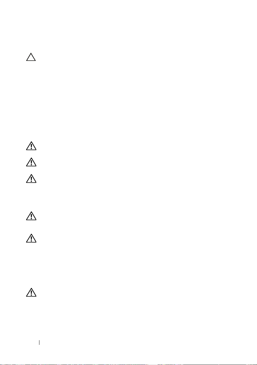
1
Pull the door latch and open the front door all the way (see Figure 1-1).
2
While holding the door, pull the top hinge pin upward so that it clears
the door’s hinge-pin housing (see Figure 1-1).
The hinge pin’s retention clip prevents the hinge from being pulled out
of the hinge body.
Figure 1-1. Removing the Front Door
2
1
1 door latch 2 hinge pin
3 hinge body 4 hinge-pin housing
8 Installation Guide
3
4
Page 11
3
While holding the hinge pin out of the door’s hinge-pin housing, pull
the door slightly away from the rack so that the door clears the hinge body.
4
Release the hinge pin.
5
Lift the door upward so that the door clears the bottom hinge post
WARNING: Due to the size and weight of the door, it is recommended that you lay
the removed door flat with the outer surface facing upward.
6
Lay the door in a safe location with the door’s outer surface facing upward.
Laying the door flat with the outer surface facing upward will help prevent
damage to the door’s badge and cosmetic coating.
Replacing the Front Door
To replace the front door, perform the steps for removal in reverse.
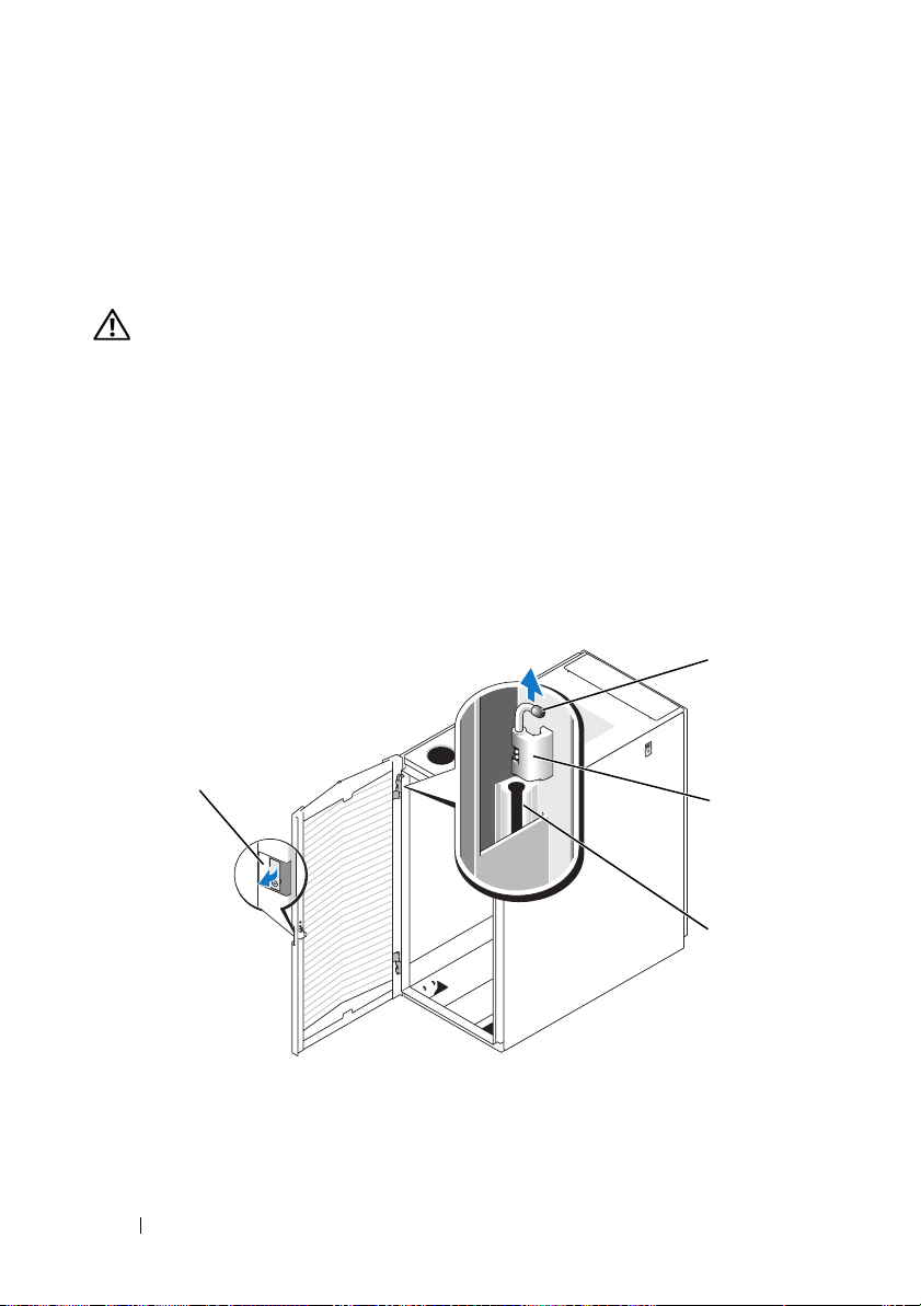
Opening and Removing the Back Doors
1
Turn the door handle and open the back doors (see Figure 1-2).
Figure 1-2. Opening the Back Doors
1
1 door handle 2 back door (2)
Installation Guide 9
2
Page 12
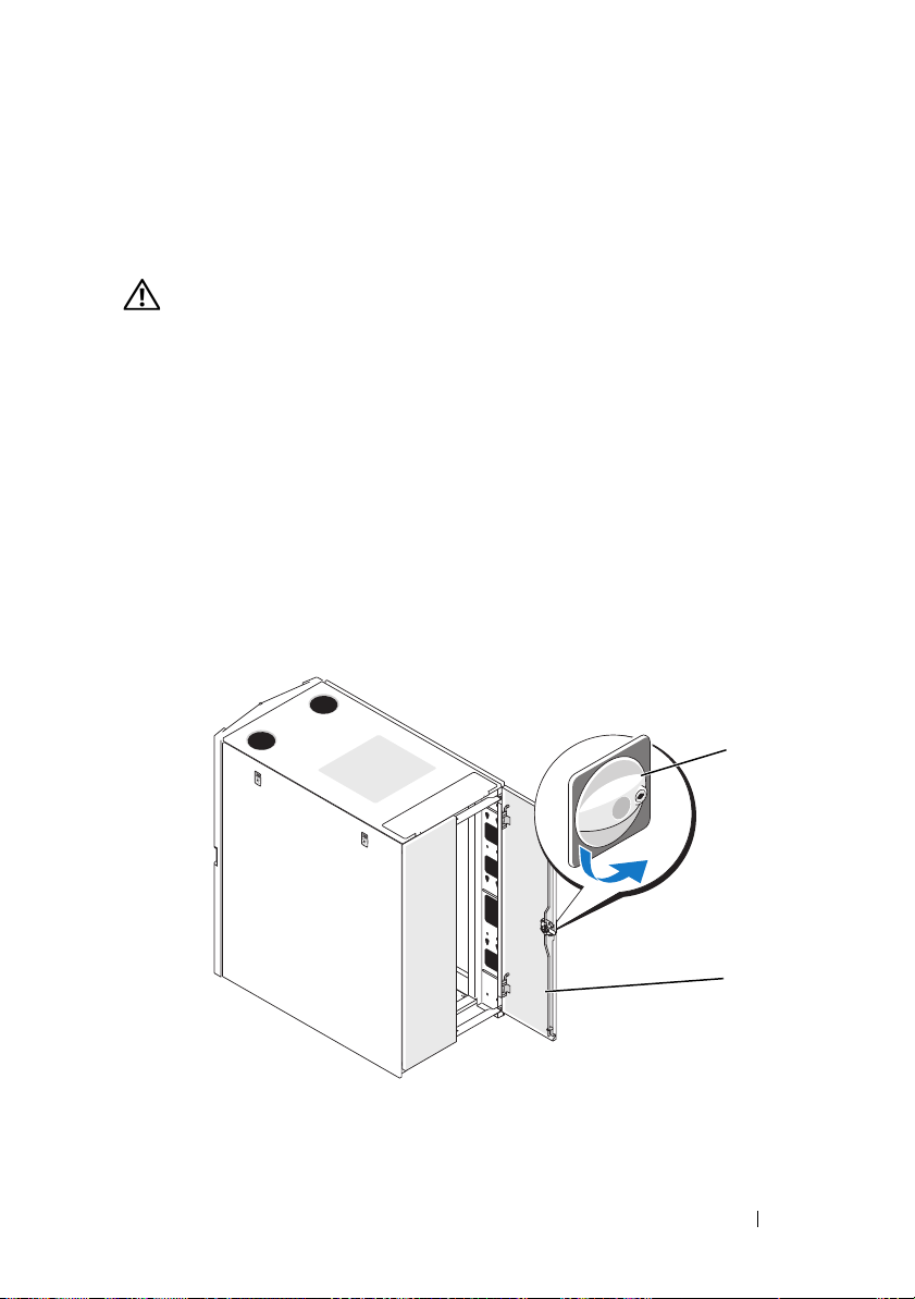
2
Remove the right door.
a
While supporting the door, pull the pin for the top hinge out
of the door’s hinge-pin housing (see Figure 1-3).
You will hear a click as you pull the pin out of the door’s hinge-pin
housing. The hinge pins are designed to prevent them from being
pulled out of the hinge body.
b
Repeat step a for the bottom hinge.
c
Pull the door away from the rack.
Figure 1-3. Removing the Back Doors
1
2
3
1 hinge pin 2 hinge body
3 hinge-pin housing
WARNING: Due to the size and weight of the door, it is recommended that you lay
the removed door flat with its outer surface facing upward.
d
Lay the door in a safe location with the door’s outer surface facing
upward.
Laying the door flat with the outer surface facing upward will help
prevent damage to the door’s cosmetic coating.
e
Repeat steps a through d for the left door.
10 Installation Guide
Page 13
Replacing the Back Doors
To replace the back doors, perform the steps for removal in reverse.
Removing and Replacing the Side Panels
CAUTION: Reinstalling the side panels is necessary before running systems
in the rack to ensure proper cooling within the rack.
NOTE: You must remove the side panels in order to install the side stabilizer feet.
NOTE: Although removing the side panels is not mandatory for installing systems in
a rack, having the sides open makes it easier to install slide assemblies and support
rails and to reverse the direction that the front door opens.
Removing the Side Panels
1
Pull both latches down and allow the side panel to swing outward slightly
at the top (see Figure 1-4).
2
Firmly grasp the sides of the panel.
3
Lift the panel upward until the panel hooks clear the holes in the bottom
of the rack frame.
4
Place the panel in a safe location with the panel’s outer surface facing
upward to help prevent damage to its cosmetic coating.
5
Repeat step 1 through step 4 for the other side panel.
Replacing the Side Panels
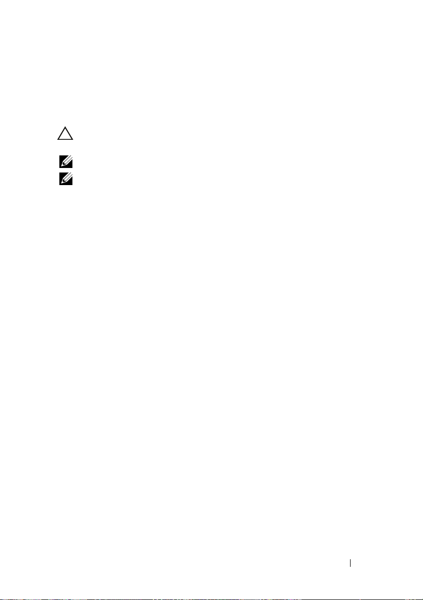
1
Lower the panel into the rack, inserting the back panel hook into the back
hole in the bottom of the rack frame and the front hook into the
corresponding hole in the front of the rack frame (see Figure 1-4).
2
Swing the top end of the panel towards the rack.
3
Press the panel into the rack until both latches lock into place.
Installation Guide 11
Page 14
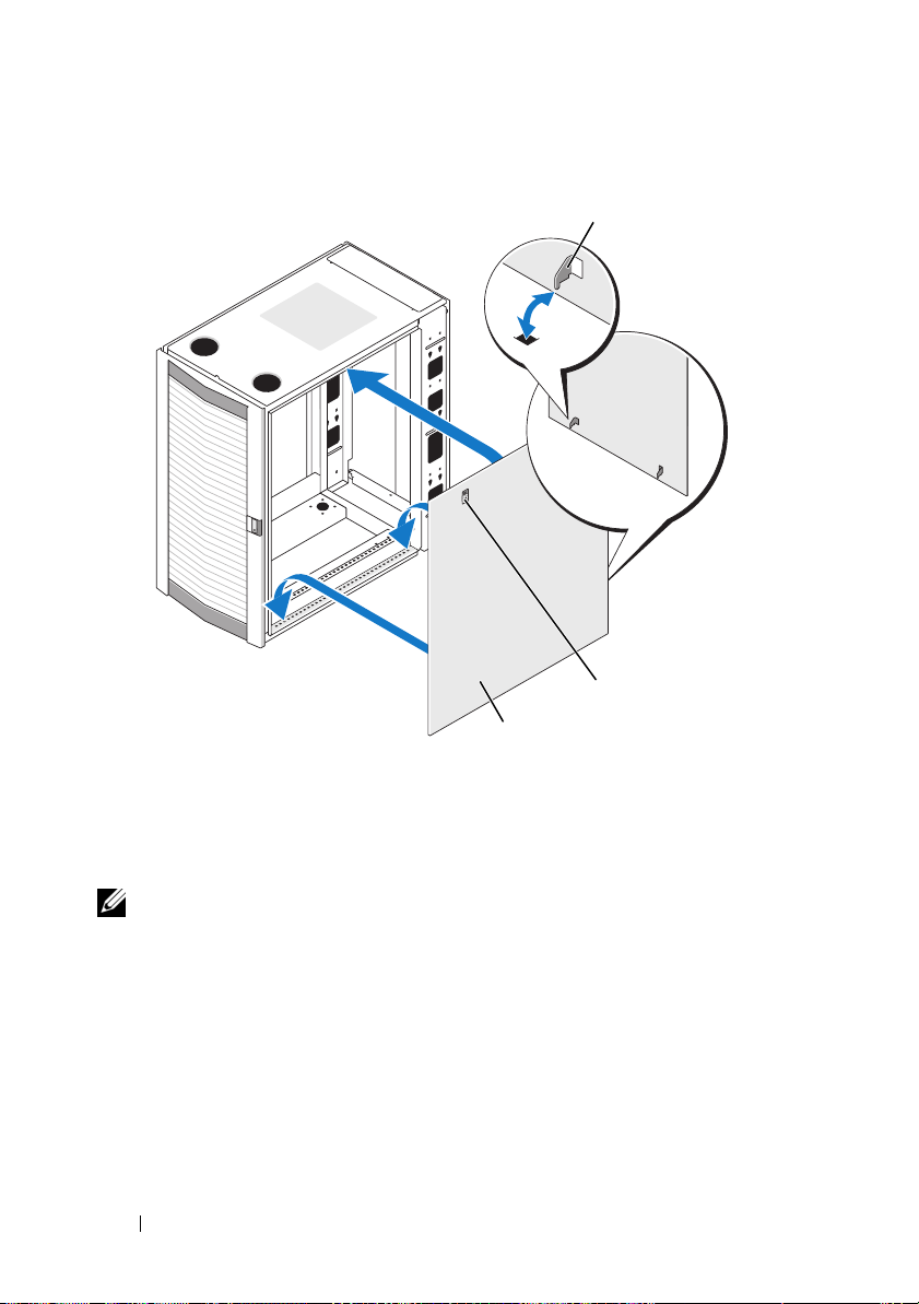
Figure 1-4. Replacing the Side Panels
1 panel hook (2) 2 latch (2)
3 side panel (2)
1
2
3
Reversing the Front Door (optional)
NOTE: Use a 4-mm Allen wrench to remove the front-door hinge bodies
from the rack and reinstall them on the side opposite their original positions.
To reverse the direction that the front door opens, complete the following steps:
1
Remove the front door (see "Removing the Front Door" on page 8).
2
Remove the side panels (see "Removing and Replacing the Side Panels"
on page 11).
12 Installation Guide
Page 15
3
Reverse the top hinge body.
a
Pull the hinge pin upward slightly so that you can access the retention
clip (see Figure 1-5).
Figure 1-5. Removing the Front-Door Hinges
1
6
5
4
1 hinge post 2 top hinge body
3 bottom hinge 4 hinge pin
5 retention clip 6 body spring
b
Using the needle-nose pliers, remove the retention clip, and then slide
2
3
the hinge pin out of the hinge body.
c
Remove the hinge spring from the hinge body.
d
Place the hinge pin, retention clip, and spring in a safe location.
e
Using the 4-mm Allen wrench, remove the Allen bolts that secure
the hinge body to the rack, and place the bolts with the hinge pin,
retention clip, and body spring.
f
Rotate the hinge body 180 degrees so that the hinge-pin holes are now
on the right side of the hinge body (see Figure 1-6).
Installation Guide 13
Page 16
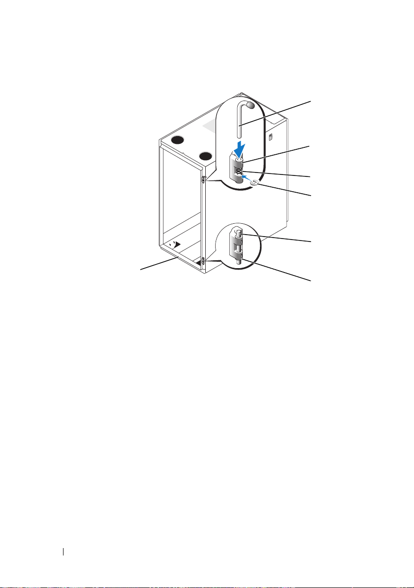
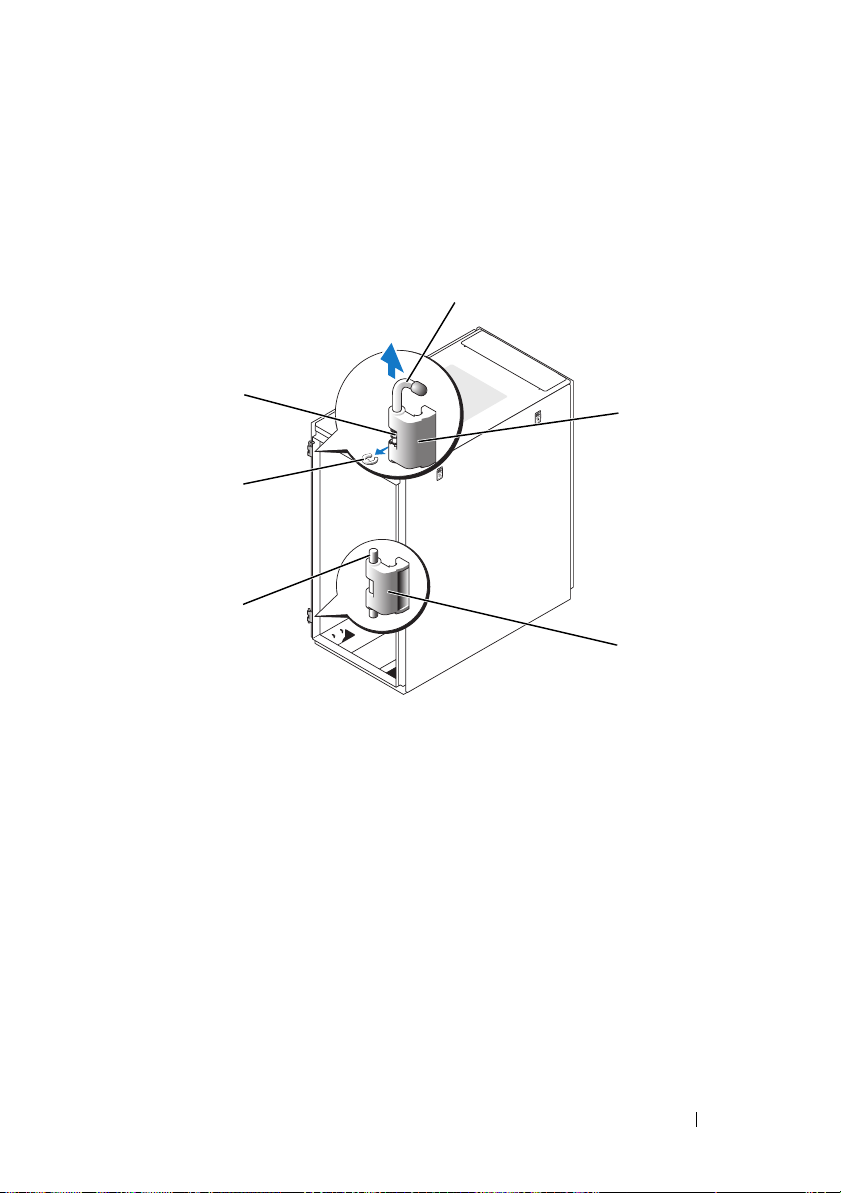
Figure 1-6. Reversing the Top and Bottom Hinges
7
1 hinge pin 2 top hinge body
3 spring 4 retention clip
5 hinge post 6 bottom hinge body
7 front of rack
1
2
3
4
5
6
g
Locate the top bolt holes in the right side of the rack, and fasten
the hinge body to the right side of the rack with the Allen bolts.
h
Insert the spring between the top and bottom hinge-pin holes
in the bottom hinge body.
i
Slide the hinge pin into the hinge body.
j
Insert the retention clip through the hinge so that the retention clip
is below the spring.
14 Installation Guide
Page 17
4
Reverse the bottom hinge body.
a
Remove the Allen bolts that secure the hinge body to the rack,
and place the bolts in a safe location.
b
Rotate the hinge body 180 degrees so that the hinge posts are now
on the right side of the hinge body (see Figure 1-6).
c
Locate the bottom bolt holes in the right side of the rack, and use
the Allen bolts to fasten the hinge body to the right side of the rack.
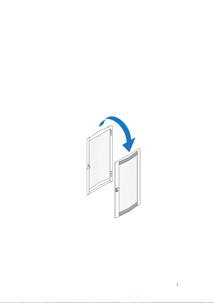
5
Rotate the front door 180 degrees so that its hinge-pin housings are
on the right side (see Figure 1-7).
Figure 1-7. Rotate Front Door
6
Rehang the front door by reversing the steps in "Removing the Front Door"
on page 8."
Installation Guide 15
Page 18
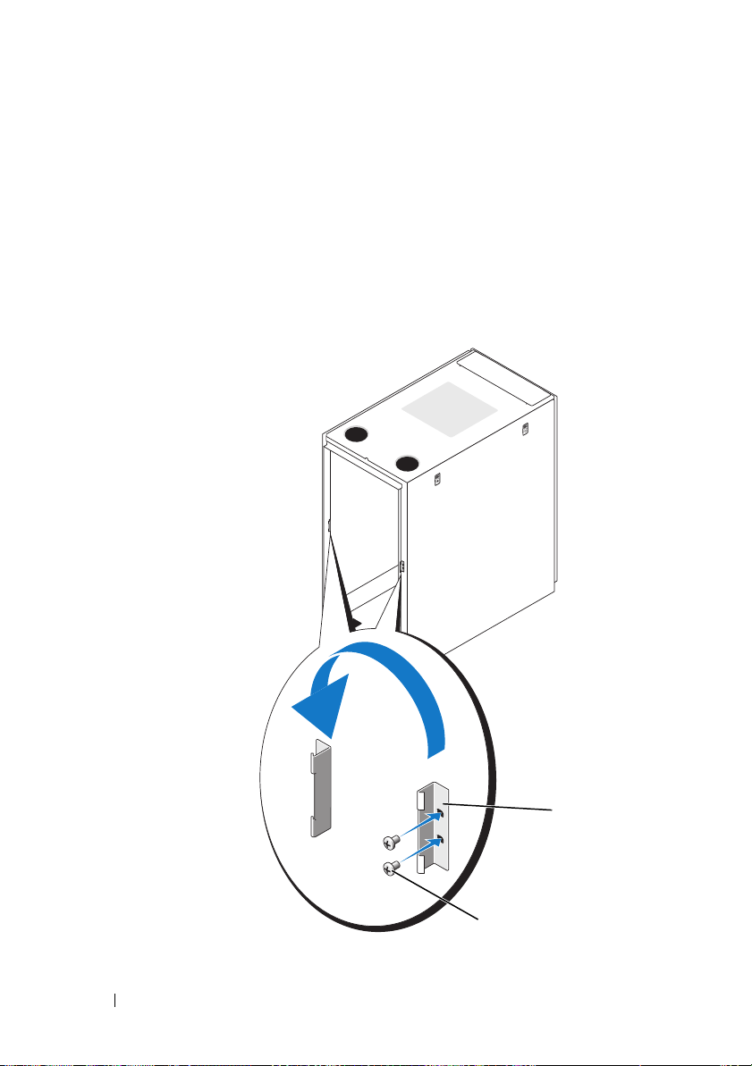
7
Reverse the lock catch.
a
Unscrew the two Phillips screws that hold the lock catch to the rack’s
vertical frame member.
b
Remove the lock catch and rotate it 180 degrees.
c
Reinstall the lock catch on the other rack front vertical frame member
by aligning the holes of the catch with the holes of the frame member
and then reinserting the two Phillips screws.
Figure 1-8. Reversing the Front Door Lock Catch
1 lock catch 2 screws
16 Installation Guide
1
2
Page 19
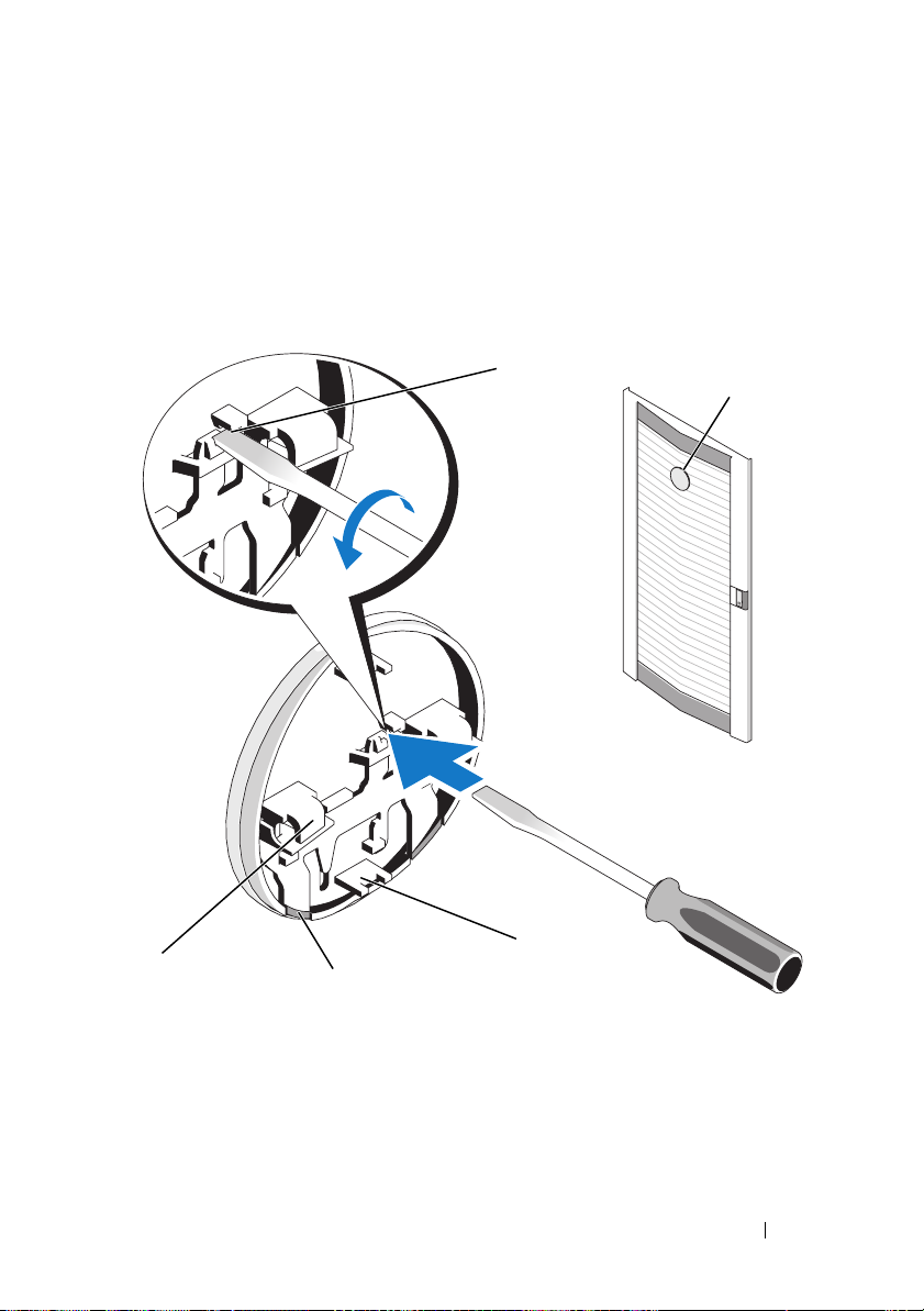
8
Reverse the badge on the front door.
a
Open the front door.
b
From inside the door, insert a flat-head screwdriver into the badge
release notch (see Figure 1-9).
Figure 1-9. Reversing the Front Door Badge
1
5
4
3
2
1 badge release notch 2 front door badge
3 center tab (2) 4 badge retention clip (2)
5 badge hook (2)
Installation Guide 17
Page 20
c
Push the screwdriver into the notch until it stops and turn it counterclockwise.
d
Lift up on the badge and pull it off the door.
e
Rotate the badge 180 degrees so that it will read correctly when
reinstalled.
f
Locate the fourth horizontal bar from the top of the door and slide
the badge hooks over it, aligning the center tabs on the badge with
the vertical bar on the door.
g
Push up on the badge retention clips until they are closed and
the badge is secure.
Securing the Rack Leveling Feet
WARNING: Read all statements below before you adjust the leveling feet.
Your rack includes four leveling feet, which are mounted on the corners of
the rack. The leveling feet are designed to align the rack in an upright, level
position when the rack is situated on a slightly uneven floor surface. Before
you install your systems in the rack, deploy and adjust the leveling feet.
When you level your rack, follow these guidelines.
WARNING: When you adjust the leveling feet, ensure that the casters on each
corner of the rack do not rise more than 9.5 mm (3/8 inch) above the floor. If you
exceed 9.5 mm of clearance between the floor and the casters as you adjust the
leveling feet, slowly retract the leveling feet, and then move the rack to another
location that requires minimal adjustments to the leveling feet.
WARNING: Adjust the leveling feet until each leveling foot rests firmly on the
floor. Proper contact with the floor ensures that each leveling foot is supporting
the weight of the rack and prevents the rack from swaying in any direction. If
the leveling feet are not all in firm contact with the floor, the rack can become
unstable and tip over.
WARNING: Do not attempt to move your rack with the leveling feet deployed.
Always retract the leveling feet before moving the rack. Having the leveling feet
deployed when you move the rack may cause the rack to tip over.
WARNING: Always level the rack and install the stabilizing feet before you
install your systems. A fully loaded rack may tip over if your rack is resting on
an uneven floor surface and the leveling and stabilizing feet are not supporting
the weight of the rack.
NOTE: If the rack is not leveled properly, you might not be able to install the
stabilizer feet, which are necessary to prevent the rack from tipping over.
18 Installation Guide
Page 21
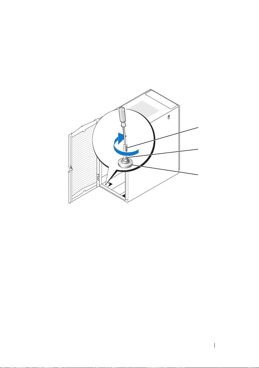
1
Using a screwdriver, lower the leveling foot until it rests on the floor.
2
If you need to lower the foot further, tighten the hex nut clockwise
with a 12-mm wrench (see Figure 1-10).
Figure 1-10. Adjusting the Leveling Feet
1 leveling foot stem 2 hex nut
3 leveling pad
1
2
3
3
Repeat steps 1 and 2 for the remaining leveling feet.
4
Ensure that the rack is level.
Installation Guide 19
Page 22
Installing the Rack Stabilizer Feet
WARNING: Installing systems in a rack without the front and side stabilizer feet
installed could cause the rack to tip over, potentially resulting in bodily injury
under certain circumstances. Therefore, always install the stabilizer feet before
installing components in the rack.
Installing the Front Stabilizer Feet
1
Open the front door.
2
Reach into the rack and pull up firmly on each stabilizer to detach
them from the frame.
3
Remove the plastic fasteners attached to the stabilizer feet.
4
Position each front stabilizer foot against the base of the rack frame
and align its holes with the corresponding holes in the frame.
5
Use the provided bolts, washers, and cage nuts to secure each foot
to the rack as shown in Figure 1-11.
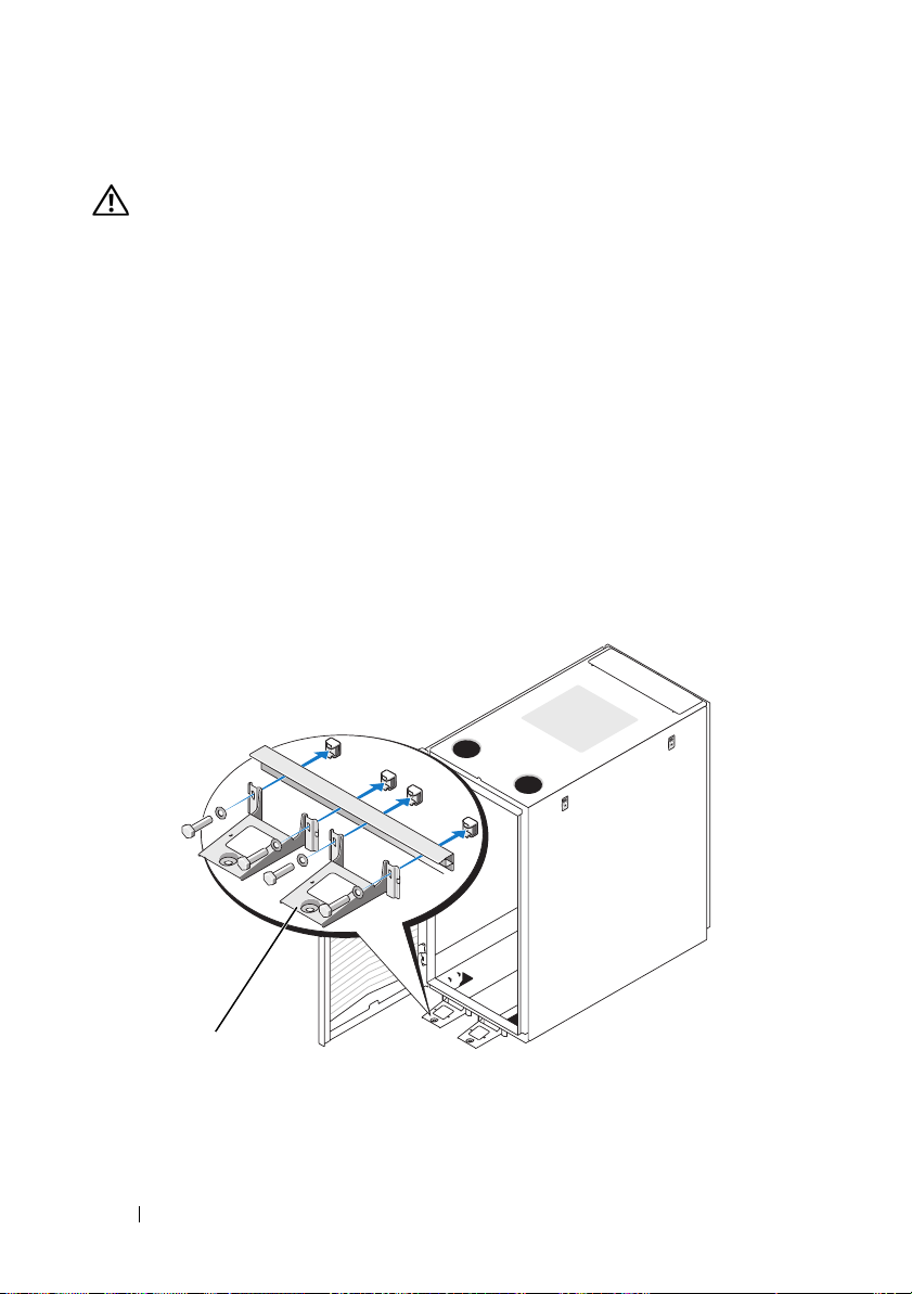
Figure 1-11. Installing the Front Stabilizer Feet
1
20 Installation Guide
1 front stabilizer foot (2)
Page 23
Installing the Side Stabilizer Feet
1
Remove the side panel.
2
On the side of the rack frame’s bottom rail, locate the four holes
(see Figure 1-12).
3
Position each stabilizer foot against the base of the rack frame and align
its holes with the corresponding holes in the frame.
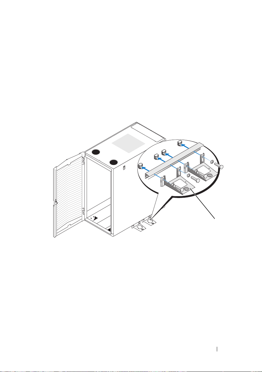
Figure 1-12. Installing the Side Stabilizer Feet
1
1 side stabilizer foot (2 per side)
4
Use the provided bolts, washers, and cage nuts to secure each foot
to the rack as shown in Figure 1-12.
Installation Guide 21
Page 24
Adjusting the Rack Posts (optional)
The position of the rack posts can be adjusted to accommodate systems
of various depths.
1
Open the rack doors.
2
Remove the screws from the bottom and top of the post (see Figure 1-13).
3
Move the post to the desired location inside the side of the rack,
and replace the screws in the corresponding holes.
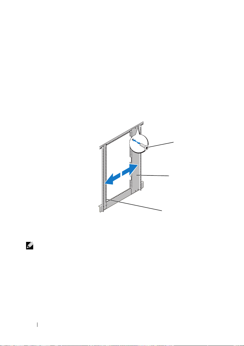
Figure 1-13. Adjusting the Rack Posts
1
2
3
1 screws 2 back rack post
3 front rack post
NOTE: You may now install systems into the rack. Use the white numbered labels
on the front and back of the rack mounting rails to help install products in the rack.
22 Installation Guide
Page 25

Routing Cables
The 24-U rack offers several features that simplify cable routing
(see Figure 1-14).
• Four power distribution unit (PDU) channels in each rack flange allow you
to route power cables to the systems mounted in the rack.
• Cable clips can be mounted in the PDU channels to keep cables out
of the way and help prevent cords from becoming tangled.
You can route cables out of the rack in two ways on a standard configuration:
• Through the cable exit at the bottom of the back doors (see Figure 1-14)
• Through the adjustable cable slot at the top of the rack and into a cable
raceway (see Figure 1-14).
Installation Guide 23
Page 26
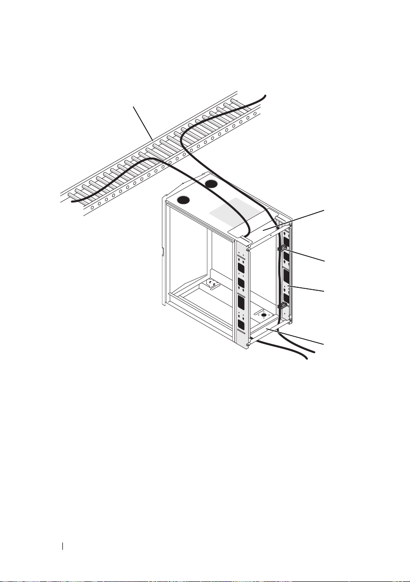
Figure 1-14. Cable-Routing Options
1
2
3
4
5
1 cable raceway 2 top cable slot
3 cable clips 4 PDU channels (2 per side)
5 bottom cable exit
24 Installation Guide
Page 27
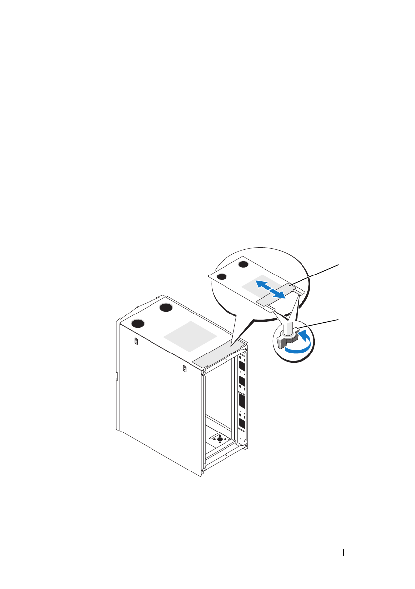
Opening and Closing the Top Cable Slot
The top cable slot in the rack can be used for routing cables up to a cable
raceway.
1
Open the back doors.
2
Loosen the wingnuts underneath the cable slot cover (see Figure 1-15).
3
Slide the cable slot cover in the open position towards the front
of the rack.
4
After routing your cables through the top of the rack, close any air gap
in the cable slot by pulling the slot cover towards the back of the rack.
Use the wingnuts to secure the cover.
Figure 1-15. Opening and Closing the Cable Slot
1
2
1 cable slot cover 2 wingnut (2)
Installation Guide 25
Page 28
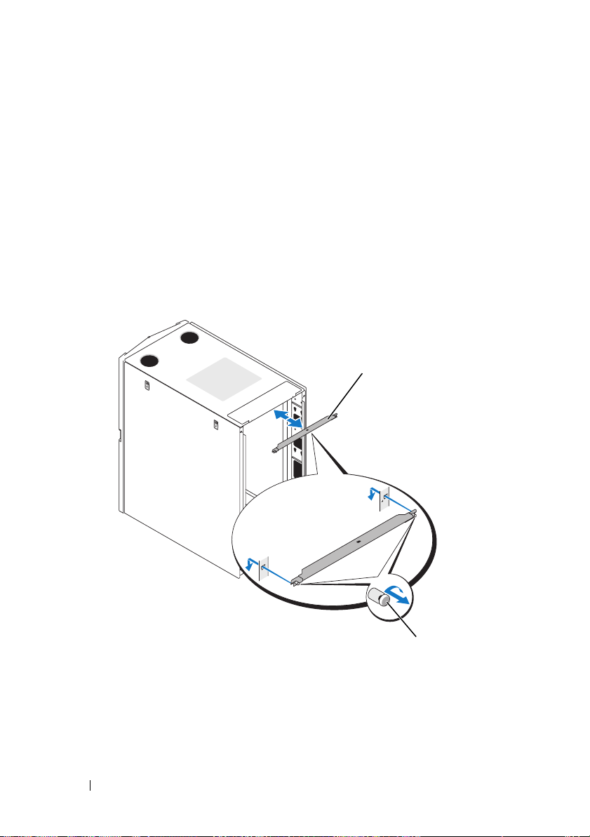
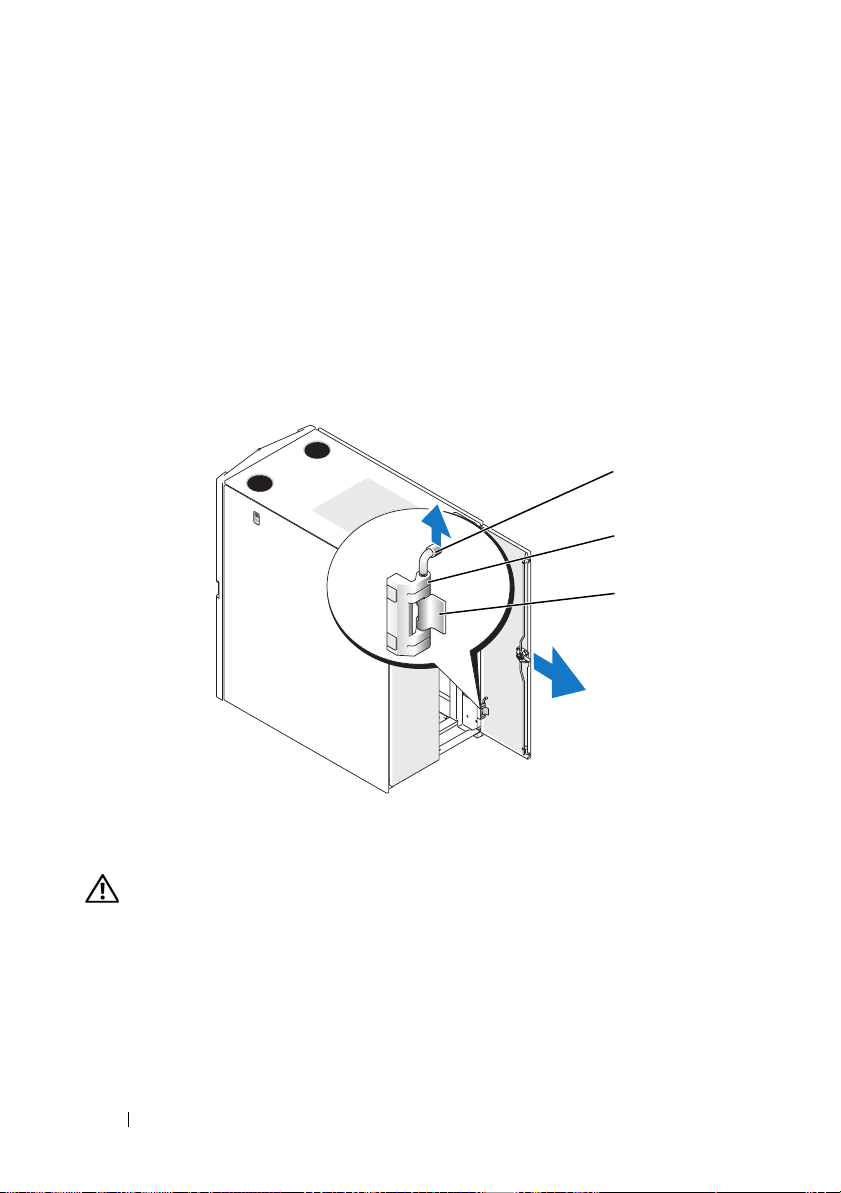
Removing and Installing the Back Door Stabilizer Bars
The top and bottom bars used to stabilize the back doors can be removed,
making it easier to route cables through the top and bottom of the rack.
1
Open the back doors.
2
Pull and hold the plungers on each side of the bar, and pull the bar up
and away from the rack (see Figure 1-16).
3
After routing your cables, replace the bars by aligning the tabs on the bars
with the corresponding holes in the rack and pushing in and down until
the plungers lock into place.
Figure 1-16. Removing and Installing the Back Door Stabilizer Bars
1
1 back door stabilizer bar (2) 2 plungers (2 per bar)
26 Installation Guide
2
Page 29

Index
B
back door
opening, 9
removing, 10
C
cables
routing, 23
D
doors
removing, 8
F
front door
removing, 8-9
reversing, 12
L
leveling feet, 18
R
rack stabilizer feet, 7, 20
routing cables, 23
S
safety instructions, 5
side panels
removing, 11
T
tools and supplies, 7
Index 27
Page 30

28 Index
Page 31

Dell™ PowerEdge™ 2420
Guide d'installation
Page 32

Remarques, précautions et avertissements
REMARQUE : Une REMARQUE indique des informations importantes qui peuvent
vous aider à mieux utiliser votre ordinateur.
PRÉCAUTION : Une PRÉCAUTION vous avertit d'un risque de dommage matériel
ou de perte de données en cas de non-respect des instructions données.
AVERTISSEMENT : Un AVERTISSEMENT vous avertit d’un risque
d'endommagement du matériel, de blessure corporelle ou de mort.
____________________
Les informations contenues dans ce document sont sujettes à modification sans préavis.
© 2008 Dell Inc. Tous droits réservés.
La reproduction de ces documents de quelque manière que ce soit sans l'autorisation écrite
de Dell Inc. est strictement interdite.
Dell, le logo DELL et PowerEdge sont des marques de Dell Inc.
D'autres marques commerciales et noms de marque peuvent être utilisés dans ce document pour faire
référence aux entités se réclamant de ces marques et de ces noms ou de leurs produits. Dell Inc. décline
tout intérêt dans l'utilisation des marques déposées et des noms de marques ne lui appartenant pas.
Octobre 2008 N/P T084M Rév. A00
Page 33

Table des matières
Consignes de sécurité . . . . . . . . . . . . . . . . . . 33
SÉCURITÉ : montage en rack des systèmes
. . . . 33
Instructions d'installation
Exigences du rack
Installation en rack
Avant de commencer
Tâches d'installation
Outils et fournitures recommandés
. . . . . . . . . . . . . . . . 33
. . . . . . . . . . . . . . . . . 34
. . . . . . . . . . . . . . . . . . . 34
. . . . . . . . . . . . . . . . 34
. . . . . . . . . . . . . . . . 35
. . . . . . . . 36
Retrait et remise en place des portes
. . . . . . . . . . . . . . . . . . . . . . . 36
du rack
Retrait et remise en place
des panneaux latéraux
. . . . . . . . . . . . . . . 40
Inversion du sens de l'ouverture
de la porte avant (facultatif)
Fixation des pieds de nivellement du rack
Installation des pieds stabilisateurs du rack
Ajustement des montants du rack (facultatif)
Acheminement des câbles
. . . . . . . . . . . . 41
. . . . . 47
. . . . 49
. . . 51
. . . . . . . . . . . . . 52
Index . . . . . . . . . . . . . . . . . . . . . . . . . . . . . . . 57
Table des matières 31
Page 34

32 Table des matières
Page 35

Consignes de sécurité
Respectez les consignes de sécurité de ce guide pour assurer votre sécurité
personnelle et pour contribuer à protéger le système et l'environnement de
travail de dommages potentiels. Pour obtenir des informations importantes
concernant la sécurité et les réglementations, consultez les consignes de sécurité
fournies avec le système. Les informations sur la garantie peuvent se trouver
dans ce document ou dans un document à part.
SÉCURITÉ : montage en rack des systèmes
Pour garantir la stabilité du rack, ainsi que votre sécurité, respectez les
précautions suivantes. Reportez-vous également à la documentation sur
l'installation en rack accompagnant le système et le rack pour connaître
les mises en garde et les procédures spécifiques.
Les systèmes sont considérés comme les composants d'un rack. Le terme
de composant fait référence à un système ainsi qu'à divers périphériques
ou du matériel de support.
PRÉCAUTION : Instructions relatives aux systèmes montés en rack :
• Votre kit pour rack est homologué pour le rack fourni uniquement. Il est
de votre devoir de vous assurer que l'installation du matériel dans un autre
rack est conforme à toutes les normes applicables. Dell décline toute
responsabilité ou garantie liée à la combinaison de ce matériel avec
d'autres types de rack.
• Avant d'installer votre matériel en rack, installez d'abord les stabilisateurs
avant et latéraux. Si vous ne le faites, pas le rack peut se renverser.
• Commencez toujours le chargement du bas vers le haut et chargez d'abord
les objets les plus lourds.
• Ne surchargez pas le circuit d'alimentation secteur du rack.
• Ne montez pas et ne vous tenez pas debout sur un composant du rack.
Instructions d'installation
Ce guide d'installation contient des instructions à l'intention de techniciens de
maintenance qualifiés, en vue de l'installation d'un rack 24U. Les informations
concernent l'assemblage du rack et le routage des câbles dans le rack.
Le rack 24U peut être installé à l'aide des outils recommandés.
Guide d'installation 33
Page 36

Exigences du rack
PRÉCAUTION : Le rack 24U est conforme aux spécifications des organismes
suivants : norme ANSI/EIA-310-D-92 de l'American National Standards Institute
(ANSI)/Electronic Industries Association (EIA), norme CEA-310-E de la Consumer
Electronics Association (CEA), norme 297 de l'International Electrotechnical
Commission (IEC) et norme 41494 de la Deutsche Industrie Norm (DIN).
Installation en rack
Avant de commencer l'installation, lisez soigneusement cette procédure
en entier.
Avant de commencer
AVERTISSEMENT : Avant de commencer l'installation du rack, lisez
soigneusement la section “Informations importantes concernant la sécurité”,
ainsi que les consignes de sécurité fournies avec le rack.
AVERTISSEMENT : Si vous installez plusieurs systèmes dans un rack, terminez
toutes les opérations requises sur le système en cours d'installation avant de
passer au suivant.
AVERTISSEMENT : Les armoires racks peuvent être extrêmement lourdes, mais
les roulettes permettent de les déplacer facilement. Les armoires ne possèdent
pas de système de freinage. Procédez avec la plus grande prudence pour déplacer
une armoire rack. Rentrez ses pieds réglables lorsque vous la changez d'emplacement. Évitez de déplacer l'armoire rack sur des surfaces rugueuses ou le long
de rampes ou de plans inclinés trop longs ou trop abrupts sur lesquels elle
pourrait vous échapper. Ressortez les pieds réglables lorsque l'armoire doit être
soutenue et pour lui éviter de se déplacer sur ses roulettes.
AVERTISSEMENT : Evitez de faire rouler l'armoire sur des surfaces rugueuses.
Tout choc brutal sur une roulette peut casser celle-ci, ce qui peut déstabiliser
et renverser l'armoire.
AVERTISSEMENT : N'essayez pas de déplacer le rack si des composants y sont
déjà installés. Si vous déplacez un rack entièrement chargé sur une surface
légèrement inégale, le rack risque d'être déséquilibré et de se renverser.
34 Guide d'installation
Page 37

Informations importantes concernant la sécurité
Respectez les consignes de sécurité décrites dans les sous-sections suivantes
lors de l'installation du système dans le rack.
AVERTISSEMENT : Vous devez respecter à la lettre les procédures de ce
document afin de garantir votre propre protection ainsi que celle d'autrui.
Le système peut être très lourd et volumineux. Une préparation et une planification
adéquates sont donc importantes afin d'éviter tout risque de blessure pour
vous-même ou autrui. Ces précautions sont d'autant plus importantes lorsque
les systèmes sont installés en hauteur.
AVERTISSEMENT: Pour des raisons de stabilité, placez un poids d'au moins
23 kilos dans les espaces 3-U du bas du rack.
Pieds stabilisateurs du rack
AVERTISSEMENT : L'installation de systèmes dans un rack sans placer de pieds
stabilisateurs avant et latéraux peut provoquer le basculement du rack et
comporte dans certaines situations un risque de blessures. C'est pourquoi, il faut
toujours installer les pieds stabilisateurs avant d'installer les composants du
rack.
AVERTISSEMENT : Après avoir installé des systèmes dans un rack, ne faites
jamais coulisser hors du rack plus d'un système à la fois. Le poids de plusieurs
systèmes sortis du rack risquerait de le faire basculer et de blesser quelqu'un.
Les pieds stabilisateurs évitent au rack de basculer lorsque vous étendez les
assemblages à glissière au maximum pour tirer un système ou un composant
hors du rack.
Tâches d'installation
L'installation d'une armoire rack comprend les opérations suivantes :
1
Retrait et remise en place des portes du rack
2
Retrait et remise en place des panneaux latéraux
3
Inversion du sens d'ouverture de la porte avant et de la plaque (facultatif)
4
Fixation des pieds de mise à niveau
5
Installation des pieds stabilisateurs
6
Ajustement des montants du rack (facultatif)
7
Routage des câbles dans le rack
Guide d'installation 35
Page 38

Outils et fournitures recommandés
Pour installer le rack, vous pourrez avoir besoin des outils et fournitures
suivants :
• Tournevis cruciforme n°2
• Tournevis à tête plate
• Clé de 12 mm
• Pince à bec fin
• Clé Allen de 4 mm (si vous souhaitez inverser le sens d'ouverture
de la porte avant)
• Les clés des portes et des panneaux latéraux du rack (livrés avec le kit
pour rack)
• Clé de 13 mm (pour retirer le rack de sa palette)
• Clé de 17 mm (pour retirer le rack de sa palette)
Retrait et remise en place des portes du rack
AVERTISSEMENT : Lorsque vous déposez les portes, placez-les à plat
pour éviter qu'elles ne tombent et blessent quelqu'un.
Retrait de la porte avant
1
Tirez le loquet et ouvrez la porte avant complètement (voir la figure 1-1).
2
Tout en maintenant la porte, tirez l'axe du gond supérieur vers le haut
afin de libérer le logement du gond de la porte (voir la figure 1-1).
Le ressort sur l'axe empêche le gond de sortir de son logement.
36 Guide d'installation
Page 39

Figure 1-1. Retrait de la porte avant
2
1
1 loquet de la porte 2 axe du gond
3 corps du gond 4 logement de l'axe du gond
3
Tout en maintenant l'axe du gond hors du logement, tirez légèrement
la porte du rack pour la dégager du logement.
4
Lâchez l'axe du gond.
5
Soulevez la porte pour la dégager du gond inférieur.
AVERTISSEMENT : Compte tenu de la taille et du poids de la porte, il
est recommandé de la poser à plat sur le sol, façade tournée vers le haut.
6
Posez la porte à l'écart en tournant sa façade vers le haut.
En procédant ainsi, vous éviterez d'endommager le macaron
et le revêtement de la porte.
3
4
Guide d'installation 37
Page 40

Remise en place de la porte avant
Pour remettre en place la porte avant, procédez à l'inverse du retrait.
Ouverture et retrait des portes arrière
1
Tournez la poignée et ouvrez les portes arrière (voir la figure 1-2).
Figure 1-2. Ouverture des portes arrière
1
2
1 poignée de la porte 2 porte arrière (2)
2
Retirez la porte de droite.
a
Tout en maintenant la porte, sortez l'axe du gond supérieur
du logement de la porte (voir la figure 1-3).
Vous devez entendre un déclic lorsque l'axe est sorti. Les axes
sont conçus pour éviter qu'ils ne sortent complètement des gonds.
b
Répétez cette opération pour l'axe inférieur.
c
Dégagez la porte du rack.
38 Guide d'installation
Page 41

Figure 1-3. Retrait des portes arrière
1 axe du gond 2 corps du gond
3 logement de l'axe du gond
AVERTISSEMENT : Compte tenu de la taille et du poids de la porte, il est
recommandé de la poser à plat sur le sol, façade tournée vers le haut.
Posez la porte à l'écart en tournant sa façade vers le haut.
d
En procédant ainsi, vous éviterez d'endommager le revêtement
de la porte.
1
2
3
e
Répétez les étapes a à d pour la porte de gauche.
Remise en place des portes arrière
Pour remettre en place les portes arrière, procédez à l'inverse du retrait.
Guide d'installation 39
Page 42

Retrait et remise en place des panneaux latéraux
PRÉCAUTION : Il est nécessaire de réinstaller les panneaux latéraux avant de
démarrer des systèmes dans le rack pour s'assurer un refroidissement adéquat
à l'intérieur du rack.
REMARQUE : Vous devez retirer les panneaux latéraux pour installer les pieds
stabilisateurs latéraux.
REMARQUE : Bien qu'il ne soit pas nécessaire de déposer les panneaux latéraux
pour installer le système dans un rack, il est plus pratique de le faire pour installer
les axes coulissants et les rails et d'inverser le sens d'ouverture des portes.
Retrait des panneaux latéraux
1
Abaissez les deux loquets et laissez le panneau latéral se détacher
légèrement vers le haut (voir la figure 1-4).
2
Saisissez fermement le panneau par ses côtés.
3
Soulevez-le jusqu'à ce que les crochets sortent de leur logement à la base
de la structure de l'armoire.
4
Déposez le panneau dans un endroit sûr, façade tournée vers le haut pour
éviter d'endommager le revêtement du panneau.
5
Répétez les étapes step 1 à step 4 pour l'autre panneau latéral.
Remise en place des panneaux latéraux
1
Abaissez le panneau dans le rack, insérez le crochet du panneau arrière
dans le trou arrière à la base de la structure du rack et le crochet avant dans
le trou correspondant à l'avant de la structure du rack (voir la figure 1-4).
2
Avancez la partie supérieure du panneau vers le rack.
3
Appuyez sur le panneau jusqu'à ce que les deux crochets se fixent
dans leur logement.
40 Guide d'installation
Page 43

Figure 1-4. Remise en place des panneaux latéraux
1 crochet du panneau (2) 2 loquet (2)
3 panneau latéral (2)
1
2
3
Inversion du sens de l'ouverture de la porte avant (facultatif)
REMARQUE : Utilisez la clé Allen de 4 mm fournie avec le rack pour retirer
les logements des gonds de la porte avant et les réinstaller sur le côté opposé.
Pour inverser le sens d'ouverture de la porte avant, procédez comme suit :
1
Retirez la porte avant (voir “Retrait de la porte avant” à la page 36).
2
Retirez les panneaux latéraux (voir “Retrait et remise en place
des panneaux latéraux” à la page 40).
Guide d'installation 41
Page 44

3
Inversez le gond supérieur.
a
Tirez légèrement l'axe vers le haut pour accéder au clip de retenue
(voir la figure 1-5).
Figure 1-5. Retrait des axes de la porte avant
1
6
5
4
1 axe du gond 2 corps du gond supérieur
3 gond inférieur 4 axe du gond
5 clip de retenue 6 ressort du corps
b
A l'aide de la pince à bec fin, retirez le clip de retenue et faites
2
3
coulisser l'axe hors du gond.
c
Retirez le ressort du gond.
d
Placez en lieu sûr l'axe, le clip de retenue et le ressort.
e
À l'aide de la clé Allen de 4 mm, retirez les vis Allen de fixation du
gond au rack et placez-les avec le gond, le clip de retenue et le ressort.
f
Faites pivoter le gond de 180 degrés pour amener les orifices du gond
sur la partie droite du gond (voir la figure 1-6).
42 Guide d'installation
Page 45

Figure 1-6. Inversion des gonds supérieur et inférieur
7
1 axe du gond 2 corps du gond supérieur
3 ressort 4 clip de retenue
5 axe du gond 6 corps du gond inférieur
7 avant du rack
1
2
3
4
5
6
g
Repérez les orifices de vis supérieurs sur la partie droite du rack
et fixez le gond à cet endroit avec les vis Allen.
h
Insérez le ressort dans les orifices des axes supérieur et inférieur,
à la base du corps du gond.
i
Glissez l'axe dans le gond.
j
Insérez le clip de retenue en le plaçant sous le ressort.
Guide d'installation 43
Page 46

4
Inversez le gond inférieur.
a
Retirez les vis Allen de fixation du gond au rack et placez-les à l'écart.
b
Faites pivoter le gond de 180 degrés pour amener les tourillons
à la droite du gond (voir la figure 1-6).
c
Repérez l'orifice de vis inférieur sur la partie droite du rack et fixez
le gond à cet endroit avec la vis Allen.
5
Faites pivoter la porte avant de 180 degrés pour amener les logements
des axes sur le côté droit (voir la figure 1-7).
Figure 1-7. Rotation de la porte avant
6
Remettez en place la porte avant en exécutant dans l'ordre inverse
les étapes de la section “Retrait de la porte avant” à la page 36.
7
Inversez le butoir de verrouillage.
a
Dévissez les deux vis Phillips n°1 qui maintiennent le butoir
de verrouillage sur la structure verticale du rack.
b
Retirez le butoir de verrouillage et faites-le pivoter de 180 degrés.
c
Réinstallez le butoir de verrouillage sur la nouvelle pièce de la
structure horizontale en faisant correspondre les trous du butoir de
verrouillage avec ceux de la structure, puis en remettant en place
les deux vis Phillips n°1.
44 Guide d'installation
Page 47

Figure 1-8. Inversion du butoir de verrouillage de la porte avant
1
1 butoir de verrouillage 2 vis
8
Inversez le macaron sur la porte avant.
a
Ouvrez la porte avant.
b
A l'intérieur de la porte, insérez un tournevis à tête plate
dans l'encoche de dégagement du macaron (voir la figure 1-9).
2
Guide d'installation 45
Page 48

Figure 1-9. Inversion du macaron de la porte avant
1
5
4
3
2
1 encoche de dégagement
du macaron
3 baguette centrale (2) 4 clip de fixation du macaron (2)
5 crochet du macaron (2)
c
Enfoncez le tournevis dans l'encoche jusqu'à atteindre le fond,
2 macaron de la porte avant
puis tournez le dans le sens inverse des aiguilles d'une montre.
d
Soulevez le macaron et décollez-le de la porte.
e
Faites pivoter le macaron de 180 degrés afin qu'il soit lisible
dans le bon sens une fois réinstallé.
46 Guide d'installation
Page 49

f
Identifiez la quatrième barre horizontale à partir du haut de la porte et
faites glisser les crochets du macaron dessus, en alignant les baguettes
centrales du macaron sur la barre verticale sur la porte.
g
Appuyez sur les clips de fixation du macaron jusqu'à ce qu'ils se
referment et que le macaron soit correctement fixé.
Fixation des pieds de nivellement du rack
AVERTISSEMENT : Lisez toutes les instructions ci-dessous avant de régler
les pieds de mise de niveau.
Votre rack est équipé de quatre pieds de mise de niveau, un par angle. Ces pieds
servent à mettre le rack parfaitement de niveau, même s'il est installé sur une
surface légèrement inégale. Avant d'installer vos systèmes dans le rack, déployez
et réglez les pieds de mise de niveau. Pour mettre le rack de niveau, respectez
les précautions suivantes.
AVERTISSEMENT : Lorsque vous réglez les pieds de nivellement, vérifiez que
les roulettes à chaque angle du rack ne dépassent pas de plus de 9,5 mm (3/8 de
pouce) au-dessus du plancher. Si le dégagement entre le plancher et les roulettes
excède 9,5 mm lors du réglage des pieds de nivellement, rentrez lentement les
pieds, puis transférez le rack à un autre emplacement ne nécessitant qu'un
ajustement minimal des pieds de nivellement.
AVERTISSEMENT : Réglez les pieds de nivellement jusqu'à ce que chacun
repose fermement sur le sol. Ceci permet de supporter le poids du rack et
l'empêche d'osciller. Si les pieds ne sont pas fermement en contact avec le sol,
le rack peut devenir instable et basculer.
AVERTISSEMENT : N'essayez pas de déplacer le rack quand les pieds de
nivellement sont déployés. Rentrez toujours les pieds de nivellement avant de
déplacer le rack. Si les pieds sont déployés quand vous déplacez le rack, il risque
de se renverser.
AVERTISSEMENT : Avant d'installer vos systèmes, installez toujours les pieds et
mettez le rack de niveau. Un rack entièrement chargé peut se renverser s'il est sur
une surface inégale et que ses pieds stabilisateurs et de mise de niveau ne
supportent pas son poids.
REMARQUE : Si le rack n'est pas correctement de niveau, vous ne pourrez pas
installer les pieds stabilisateurs qui lui évitent de basculer.
Guide d'installation 47
Page 50

1
À l'aide d'un tournevis, abaissez le pied stabilisateur jusqu'à ce qu'il touche
le sol.
2
Si vous avez besoin d'abaisser davantage le pied, resserrez l'écrou 6 pans
à l'aide d'une clé 12 mm (voir la figure 1-10).
Figure 1-10. Réglage des pieds de nivellement
1
2
3
1 axe du pied de nivellement 2 écrou 6 pans
3 patin de nivellement
3
Répétez les étapes 1 et 2 pour les autres pieds de nivellement.
4
Vérifiez que le rack est bien de niveau.
48 Guide d'installation
Page 51

Installation des pieds stabilisateurs du rack
AVERTISSEMENT : L'installation de systèmes dans un rack sans placer de pieds
stabilisateurs avant et latéraux peut provoquer le basculement du rack et
comporte dans certaines situations un risque de blessures. C'est pourquoi,
il faut toujours installer les pieds stabilisateurs avant d'installer les composants
du rack.
Installation des pieds stabilisateurs avant
1
Ouvrez la porte avant.
2
A l'intérieur du rack, tirez fermement sur chaque stabilisateur pour
le détacher de la structure.
3
Retirez les attaches en plastique qui retiennent les pieds stabilisateurs.
4
Placez chaque pied stabilisateur avant contre la base de la structure
du rack et faites correspondre ses trous avec ceux de la structure.
5
Utilisez les écrous, rondelles et écrous à cage fournis pour fixer chaque
pied au rack comme illustré dans la figure 1-11.
Figure 1-11. Installation des pieds stabilisateurs avant
1
1 pied stabilisateur avant (2)
Guide d'installation 49
Page 52

Installation des pieds stabilisateurs latéraux
1
Retirez le panneau latéral.
2
Sur le côté du rail inférieur de la structure du rack, repérez les quatre trous
(voir la figure 1-12).
3
Placez chaque pied stabilisateur contre la base de la structure du rack
et faites correspondre ses trous avec ceux de la structure.
Figure 1-12. Installation des pieds stabilisateurs latéraux
1
1 pied stabilisateur latéral (2 par côté)
4
Utilisez les écrous, rondelles et écrous à cage fournis pour fixer chaque
pied au rack comme illustré dans la figure 1-12.
50 Guide d'installation
Page 53

Ajustement des montants du rack (facultatif)
Vous pouvez ajuster les montants du rack pour recevoir des systèmes
de profondeur différente.
1
Ouvrez les portes du rack.
2
Retirez les vis des parties supérieure et inférieure du montant
(voir la figure 1-13).
3
Déplacez le montant à l'endroit désiré à l'intérieur de la partie latérale
du rack, puis replacez les vis dans les trous correspondants.
Figure 1-13. Ajustement des montants du rack
1
2
3
1 vis 2 montant arrière du rack
3 montant avant du rack
REMARQUE : Vous pouvez maintenant installer les systèmes dans le rack. Utilisez
les étiquettes numérotées blanches situées sur la partie avant et la partie arrière
des rails de montage du rack pour vous aider dans l'installation des composants.
Guide d'installation 51
Page 54

Acheminement des câbles
Le rack 24U dispose de plusieurs éléments qui simplifient le routage des câbles
(voir la figure 1-14).
• Quatre canaux d'unité de distribution de l'alimentation (PDU) présents
dans chaque plaque permettent de faire cheminer les câbles
d'alimentation des systèmes montés sur le rack.
• Vous pouvez monter les clips des câbles dans les canaux PDU afin
de ranger les câbles et d'empêcher les fils de s'entremêler.
Vous pouvez faire passer les câbles hors du rack de deux manières différentes
pour une configuration standard :
• Par la sortie de câble au bas des portes arrière (voir la figure 1-14)
• Par la fente de câble réglable dans la partie supérieure du rack et à travers
le chemin de câbles (voir la figure 1-14).
52 Guide d'installation
Page 55

Figure 1-14. options de routage des câbles
1
2
3
4
5
1 chemin de câbles 2 fente de câble supérieure
3 clips de câbles 4 canaux PDU (2 par côté)
5 sortie de câble inférieure
Guide d'installation 53
Page 56

Ouverture et fermeture de la sortie de câble supérieure
La sortie de câble supérieure du rack permet de faire passer les câbles
vers un chemin de câbles.
1
Ouvrez les portes arrière.
2
Desserrez les écrous à ailettes sous le cache du logement de câble
(voir la figure 1-15).
3
Ouvrez le cache du logement de câble en le faisant glisser vers l'avant
du rack.
4
Après avoir fait passer vos câbles par le haut du rack, refermez toute
interstice visible en tirant le cache du logement vers l'arrière du rack.
Fixez le cache à l'aide des écrous à ailettes.
Figure 1-15. Ouverture et fermeture de l'emplacement des câbles
1
2
1 cache des orifices de câble 2 écrou à ailettes (2)
54 Guide d'installation
Page 57

Retrait et installation des barres de stabilisation de la porte arrière
Il est possible de retirer les barres supérieure et inférieure qui stabilisent les
portes arrière, afin de faciliter le passage des câbles par le haut et le bas du rack.
1
Ouvrez les portes arrière.
2
Tirez et maintenez les plots de chaque côté de la barre, puis dégagez
cette dernière du rack en la tirant vers le haut (voir la figure 1-16).
3
Après avoir fait passer vos câbles, replacez les barres en alignant les
baguettes avec les orifices correspondants du rack, puis en les insérant
et en appuyant jusqu'à ce que les plots se fixent en place.
Figure 1-16. Retrait et installation des barres de stabilisation de la porte arrière
1
1 barre de stabilisation
de la porte arrière (2)
2
2 plots (2 par barre)
Guide d'installation 55
Page 58

56 Guide d'installation
Page 59

Index
C
Câbles
routage, 52
Consignes de sécurité, 33
Couvercle arrière
ouverture, 38
retrait, 38
Couvercle avant
inversion, 41
retrait, 36, 38
O
Outils et fournitures, 36
P
Panneaux latéraux
retrait, 40
pieds de mise de niveau, 47
Portes
retrait, 36
R
Rack, pieds stabilisateurs, 35, 49
Routage des câbles, 52
Index 57
Page 60

58 Index
Page 61

Dell™ PowerEdge™ 2420
Installationsanleitung
Page 62

Anmerkungen, Vorsichtshinweise und Warnungen
ANMERKUNG: Eine ANMERKUNG macht auf wichtige Informationen
aufmerksam, mit denen Sie das System besser einsetzen können.
VORSICHT: Hiermit werden Sie auf mögliche Gefahrenquellen hingewiesen,
die Hardwareschäden oder Datenverlust zur Folge haben können, wenn die
Anweisungen nicht befolgt werden.
WARNUNG: Hiermit werden Sie auf eine potenziell gefährliche Situation
hingewiesen, die zu Sachschäden, Verletzungen oder zum Tod führen könnte.
____________________
Irrtümer und technische Änderungen vorbehalten.
© 2008 Dell Inc. Alle Rechte vorbehalten.
Eine Vervielfältigung oder Wiedergabe dieser Materialien in jeglicher Weise ohne vorherige
schriftliche Genehmigung von Dell Inc. ist strengstens untersagt.
Dell, das DELL Logo und PowerEdge sind Marken von Dell Inc.
Alle anderen in dieser Dokumentation genannten Marken und Handelsbezeichnungen sind Eigentum
der entsprechenden Hersteller und Firmen. Dell Inc. erhebt keinen Anspruch auf Marken und
Handelsbezeichnungen mit Ausnahme der eigenen.
Oktober 2008 Teilenr. T084M Rev. A00
Page 63

Inhalt
Sicherheitshinweise. . . . . . . . . . . . . . . . . . . 63
SICHERHEIT: Systeme im Rack montieren
. . . . . 63
Installationsanleitung
Rackanforderungen
Rackinstallation
Bevor Sie beginnen
Ablauf der Installation
Empfohlene Werkzeuge und Zubehör
. . . . . . . . . . . . . . . . . . 64
. . . . . . . . . . . . . . . . 64
. . . . . . . . . . . . . . . . . . . . . 64
. . . . . . . . . . . . . . . . . 64
. . . . . . . . . . . . . . . 65
. . . . . . . 66
Entfernen und Wiederanbringen
der Racktüren
. . . . . . . . . . . . . . . . . . . . 66
Entfernen und Wiederanbringen
der Seitenteile
. . . . . . . . . . . . . . . . . . . 70
Umgekehrtes Einbauen der vorderen Tür
(optional)
Einstellen der höhenverstellbaren Rackfüße
Anbringen der Stabilisatoren
Anpassen der Rackstützen (optional)
Verlegen der Kabel
. . . . . . . . . . . . . . . . . . . . . . 71
. . . 77
. . . . . . . . . . . . 79
. . . . . . . 81
. . . . . . . . . . . . . . . . . 82
Stichwortverzeichnis . . . . . . . . . . . . . . . . . . 87
Inhalt 61
Page 64

62 Inhalt
Page 65

Sicherheitshinweise
Beachten Sie die nachfolgenden Sicherheitshinweise, um Ihre eigene Sicherheit
zu gewährleisten und eine Beschädigung des Systems und der Arbeitsumgebung
zu vermeiden. Die vollständigen wichtigen Informationen zu Sicherheitsanforderungen und Betriebsvorschriften finden Sie in den Sicherheitshinweisen,
die Sie mit dem System erhalten haben. Die Garantieinformationen befinden
sich entweder dort oder in einem gesonderten Dokument.
SICHERHEIT: Systeme im Rack montieren
Folgende Vorsichtsmaßnahmen dienen der Stabilität und Sicherheit des Racks.
Spezielle Warnungen und/oder Sicherheitshinweise und Prozeduren finden Sie
auch in der zum System gehörenden Dokumentation zur Rackinstallation.
Systeme gelten als Komponenten in einem Rack. Der Begriff „Komponente“
bezieht sich auf alle Systeme sowie auf verschiedene Peripheriegeräte oder
unterstützende Hardware.
VORSICHT: Anleitungen für rackmontierte Systeme:
• Das Rack-Kit ist nur für den gelieferten Rackschrank zugelassen. Es liegt
in Ihrer Verantwortung, dafür zu sorgen, dass die Installation des Systems
in einem anderen Rack allen zutreffenden Standards entspricht.
Dell übernimmt keinerlei Haftung und Gewährleistung bezüglich
der Kombination des Systems mit einem anderen Rack.
• Bringen Sie alle vorderen und seitlichen Stabilisatoren an, bevor Sie
das System in einem Rack installieren. Wenn Sie die Stabilisatoren
nicht anbringen, kann das Rack umkippen.
• Setzen Sie die Komponenten immer von unten nach oben ein und setzen
Sie immer zuerst die schwersten Elemente ein.
• Überlasten Sie nicht den Wechselstromkreis für das Rack.
• Stellen Sie sich nicht auf Komponenten im Rack und treten Sie
nicht darauf.
Installationsanleitung 63
Page 66

Installationsanleitung
Diese Installationsanleitung enthält Anweisungen für geschulte Servicetechniker
zur Installation eines 24-U-Racks (Rack mit 24 Einheiten). Sie erfahren unter
anderem, wie Sie das Rack montieren und Kabel durch das Rack verlegen.
Das 24-U-Rack kann mit den empfohlenen Werkzeugen installiert werden.
Rackanforderungen
VORSICHT: Das 24-U-Rack erfüllt die Spezifikationen American National
Standards Institute (ANSI)/Electronic Industries Association (EIA) ANSI/EIA-310D-92, Consumer Electronics Association (CEA) Standard CEA-310-E, International
Electrotechnical Commission (IEC) 297 und Deutsche Industrie Norm (DIN) 41494.
Rackinstallation
Bevor Sie mit der Installation beginnen, lesen Sie diese gesamte Prozedur
sorgfältig durch.
Bevor Sie beginnen
WARNUNG: Lesen Sie aufmerksam den Abschnitt „Wichtige
Sicherheitshinweise“ sowie die Sicherheitsanweisungen, die Sie mit dem Rack
erhalten haben.
WARNUNG: Wenn Sie mehrere Systeme in einem Rack installieren, schließen
Sie alle Maßnahmen für ein System ab, bevor Sie das nächste System installieren.
WARNUNG: Gestellschränke können sehr schwer sein und leicht wegrollen. Die
Schränke haben keine Bremsen. Bewegen Sie ein Rack nur mit größter Vorsicht.
Fahren Sie die höhenverstellbaren Füße ein, bevor Sie ein Rack bewegen.
Vermeiden Sie lange bzw. steile Neigungen, unebene Oberflächen oder Rampen,
auf denen Sie die Kontrolle über das Rack verlieren könnten. Fahren Sie die
höhenverstellbaren Füße aus, damit das Rack abgestützt wird und nicht wegrollen
kann.
WARNUNG: Rollen Sie das Rack nicht über unebene oder grobe Oberflächen.
Harte Stöße auf die Rollen können dazu führen, dass sie brechen, sodass das Rack
instabil wird und umkippt.
WARNUNG: Versuchen Sie nicht, das Rack zu bewegen, wenn Komponenten
darin installiert sind. Wenn Sie ein beladenes Rack auf einem leicht unebenen
Untergrund verschieben, könnte das Rack aus dem Gleichgewicht geraten
und umkippen.
64 Installationsanleitung
Page 67

Wichtige Sicherheitshinweise
Beachten Sie beim Einbau des Systems im Rack die Sicherheitsmaßnahmen
in den folgenden Unterabschnitten.
WARNUNG: Befolgen Sie die in diesem Dokument angegebenen
Vorgehensweisen genau, um sich selbst und andere Personen nicht zu gefährden.
Das System ist möglicherweise sehr groß und schwer. Sie sollten die Installation
sorgfältig vorbereiten und planen, um Verletzungen zu vermeiden. Dies gilt
besonders, wenn Systeme weiter oben im Rack installiert werden.
WARNUNG: Aus Stabilitätsgründen müssen immer mindestens 23 kg
in den unteren drei Einheiten des Rackschranks eingebaut werden.
Rackstabilisatoren
WARNUNG: Werden Systeme in einem Rack installiert, an dem die vorderen und
seitlichen Stabilisatoren fehlen, kann das Rack umkippen, was unter Umständen
schwere Verletzungen nach sich ziehen kann. Befestigen Sie daher immer zuerst
die Stabilisatoren, bevor Sie Komponenten im Rack installieren.
WARNUNG: Wenn Sie Systeme in einem Rack installiert haben, ziehen Sie
niemals mehr als ein System gleichzeitig auf den Laufschienen aus dem Rack.
Durch das Gewicht von mehr als einem herausgezogenen System kann das Rack
umkippen und Verletzungen verursachen.
Die Stabilisatoren verhindern, dass das Rack umkippt, wenn ein System oder
eine andere Komponente auf den Laufschienen vollständig aus dem Rack
gezogen wird.
Ablauf der Installation
Die Installation eines Rackschranks umfasst die folgenden Aufgaben:
1
Entfernen und Wiederanbringen der Racktüren
2
Entfernen und Wiederanbringen der Seitenteile
3
Umgekehrtes Einbauen der vorderen Tür und Plakette (optional)
4
Einstellen der höhenverstellbaren Füße
5
Anbringen der Stabilisatoren
6
Anpassen der Rackstützen (optional)
7
Verlegen der Kabel im Rack
Installationsanleitung 65
Page 68

Empfohlene Werkzeuge und Zubehör
Für die Installation des Racks benötigen Sie eventuell folgende Werkzeuge
und Zubehörteile:
• Kreuzschlitzschraubendreher Größe 2
• Senkkopfschraubendreher
• 12-mm-Schraubenschlüssel
• Spitzzange
• 4-mm-Inbusschlüssel (wenn Sie die Tür so einbauen möchten,
dass sie sich in entgegengesetzter Richtung öffnen lässt)
• Schlüssel für die Racktüren und Seitenteile (im Rack-Kit enthalten)
• 13-mm-Schraubenschlüssel (um das Rack vom Lager zu entfernen)
• 17-mm-Schraubenschlüssel (um das Rack vom Lager zu entfernen)
Entfernen und Wiederanbringen der Racktüren
WARNUNG: Legen Sie die Türen flach auf den Boden, damit sie nicht umfallen
und jemanden verletzen können.
Entfernen der vorderen Tür
1
Ziehen Sie an der Türverriegelung und öffnen Sie die vordere Tür
vollständig (siehe Abbildung 1-1).
2
Halten Sie die Tür fest und ziehen Sie den oberen Scharnierstift
nach oben aus dem Scharnierstiftgehäuse heraus (siehe Abbildung 1-1).
Der Halteclip des Scharnierstifts verhindert, dass das Scharnier aus
dem Scharniergehäuse gezogen werden kann.
66 Installationsanleitung
Page 69

Abbildung 1-1. Vordere Tür entfernen
2
1
1 Türverriegelung 2 Scharnierstift
3 Scharniergehäuse 4 Scharnierstiftgehäuse
3
Halten Sie den aus dem Scharnierstiftgehäuse gezogenen Scharnierstift
3
4
weiterhin fest und ziehen Sie die Tür vorsichtig von dem Rack weg,
sodass die Tür aus dem Scharniergehäuse gleitet.
4
Lassen Sie den Scharnierstift los.
5
Heben Sie die Tür nach oben an, sodass sie aus der unteren Scharnierleiste
gleitet.
WARNUNG: Wegen der Größe und des Gewichts der Tür wird empfohlen,
diese nach dem Abnehmen mit der Außenfläche nach oben flach hinzulegen.
6
Bewahren Sie die Tür mit der Außenfläche nach oben an einem sicheren
Platz auf.
Wenn Sie die Tür flach und mit der Außenfläche nach oben hinlegen,
vermeiden Sie Schäden an der Plakette und an der Beschichtung der Tür.
Installationsanleitung 67
Page 70

Wiederanbringen der vorderen Tür
Um die Tür wieder anzubringen, wiederholen Sie die Schritte zum Entfernen
der Tür in der umgekehrten Reihenfolge.
Öffnen und Abnehmen der hinteren Türen
1
Drehen Sie den Türgriff und öffnen Sie die hinteren Türen
(siehe Abbildung 1-2).
Abbildung 1-2. Hintere Türen öffnen
1
2
1 Türgriff 2 Hintere Türen (2)
2
Nehmen Sie die rechte Tür ab.
a
Halten Sie die Tür fest und ziehen Sie den Stift des oberen Scharniers
aus dem Scharnierstiftgehäuse der Tür (siehe Abbildung 1-3).
Wenn Sie den Stift aus dem Scharnierstiftgehäuse ziehen,
ist ein Klicken zu hören. Die Scharnierstifte sind so konzipiert,
dass sie nicht aus dem Scharniergehäuse gezogen werden können.
b
Wiederholen Sie Schritt a für das untere Scharnier.
c
Ziehen Sie die Tür von dem Rack weg.
68 Installationsanleitung
Page 71

Abbildung 1-3. Hintere Türen abnehmen
1 Scharnierstift 2 Scharniergehäuse
3 Scharnierstiftgehäuse
WARNUNG: Wegen der Größe und des Gewichts der Tür wird empfohlen,
diese nach dem Abnehmen mit der Außenfläche nach oben flach hinzulegen.
Bewahren Sie die Tür mit der Außenfläche nach oben an einem
d
sicheren Platz auf.
Wenn Sie die Tür flach und mit der Außenfläche nach oben hinlegen,
vermeiden Sie Schäden an der Beschichtung der Tür.
1
2
3
e
Wiederholen Sie die Schritte a bis d für die linke Tür.
Wiederanbringen der hinteren Türen
Um die hinteren Türen wieder anzubringen, wiederholen Sie die Schritte
zum Entfernen der Türen in der umgekehrten Reihenfolge.
Installationsanleitung 69
Page 72

Entfernen und Wiederanbringen der Seitenteile
VORSICHT: Die Seitenteile müssen wieder angebracht werden, bevor Systeme im
Rack betrieben werden, um die ausreichende Kühlung im Rack sicherzustellen.
ANMERKUNG: Um die Stabilisatoren montieren zu können, müssen Sie die
Seitenteile abnehmen.
ANMERKUNG: Für die Installation von Systemen in einem Rack ist es nicht
absolut erforderlich, die Seitenteile abzunehmen. Allerdings lassen sich Gleit- und
Stützschienen leichter einbauen, wenn die Seitenteile abgenommen wurden, und
Sie können die vordere Tür so einbauen, dass sie sich in die entgegengesetzte
Richtung öffnet.
Entfernen der Seitenteile
1
Ziehen Sie beide Sicherungen nach unten und lassen Sie das Seitenteil
oben etwas nach außen klappen (siehe Abbildung 1-4).
2
Fassen Sie die Kanten des Seitenteils fest an.
3
Heben Sie das Seitenteil nach oben, bis die Haken des Seitenteils
nicht mehr in den Öffnungen unten am Rackrahmen sitzen.
4
Legen Sie das Seitenteil mit der Außenfläche nach oben an einen sicheren
Ort, um Beschädigungen an der Beschichtung zu vermeiden.
5
Wiederholen Sie Schritt 1 bis Schritt 4 für das andere Seitenteil.
Wiedereinbauen der Seitenteile
1
Setzen Sie das Seitenteil in das Rack. Achten Sie darauf, dass der hintere
Haken am Seitenteil in die hintere Öffnung unten am Rackrahmen und
der vordere Haken am Seitenteil in die entsprechende Öffnung auf der
Vorderseite des Rackrahmens eingesetzt wird (siehe Abbildung 1-4).
2
Klappen Sie das obere Ende des Seitenteils zum Rack hin.
3
Drücken Sie das Seitenteil in das Rack, bis beide Sicherungen einrasten.
70 Installationsanleitung
Page 73

Abbildung 1-4. Seitenteile wieder anbringen
1 Haken am Seitenteil (2) 2 Sicherungen (2)
3 Seitenteile (2)
1
2
3
Umgekehrtes Einbauen der vorderen Tür (optional)
ANMERKUNG: Nehmen Sie mithilfe eines 4-mm-Inbusschlüssel die Scharnier-
gehäuse der vorderen Tür vom Rack ab. Montieren Sie die Gehäuse dann so,
dass sie ihrer ursprünglichen Einbauposition gegenüberliegen.
Unter Beachtung der folgenden Schritte lässt sich die Tür in entgegengesetzter
Richtung öffnen:
1
Nehmen Sie die vordere Tür ab (siehe „Entfernen der vorderen Tür“
auf Seite 66).
2
Entfernen Sie die Seitenteile (siehe „Entfernen und Wiederanbringen
der Seitenteile“ auf Seite 70).
Installationsanleitung 71
Page 74

3
Drehen Sie das obere Scharniergehäuse um.
a
Ziehen Sie den Scharnierstift vorsichtig nach oben, sodass Sie
auf den Halteclip zugreifen können (siehe Abbildung 1-5).
Abbildung 1-5. Scharniere für die vordere Tür abnehmen
1
6
5
4
1 Scharnierleiste 2 Oberes Scharniergehäuse
3 Unteres Scharnier 4 Scharnierstift
5 Halteklammer 6 Scharnierfeder
b
Entfernen Sie den Halteclip mit der Spitzzange und lassen Sie
2
3
dann den Scharnierstift aus dem Scharniergehäuse gleiten.
c
Nehmen Sie die Scharnierfeder aus dem Scharniergehäuse.
d
Bewahren Sie den Scharnierstift, den Halteclip und die Feder gut auf.
72 Installationsanleitung
Page 75

e
Entfernen Sie mit einem 4-mm-Inbusschlüssel die Inbusbolzen, mit
deren Hilfe das Scharniergehäuse am Rack befestigt ist. Bewahren Sie
die Bolzen zusammen mit dem Scharnierstift, dem Halteclip und
der Scharnierfeder auf.
f
Drehen Sie das Scharniergehäuse um 180 Grad, sodass die Scharnierstiftlöcher sich auf der rechten Seite des Scharnierloches befinden
(siehe Abbildung 1-6).
Abbildung 1-6. Oberes und unteres Scharnier umdrehen
1
2
3
4
5
7
6
1 Scharnierstift 2 Oberes Scharniergehäuse
3 Feder 4 Halteklammer
5 Scharnierleiste 6 Unteres Scharniergehäuse
7 Rackvorderseite
g
Suchen Sie die oberen Bolzenlöcher auf der rechten Rackseite.
Befestigen Sie darin das Scharniergehäuse mithilfe der Inbusbolzens.
h
Fügen Sie die Feder zwischen dem oberen und dem unteren
Scharnierstiftloch des unteren Scharniergehäuses ein.
i
Lassen Sie den Scharnierstift in das Scharniergehäuse gleiten.
j
Fügen Sie den Halteclip unterhalb der Feder in das Scharnier ein.
Installationsanleitung 73
Page 76

4
Drehen Sie das untere Scharniergehäuse um.
a
Entfernen Sie die Inbusbolzen, mit deren Hilfe das Scharniergehäuse
am Rack befestigt ist. Bewahren Sie die Bolzen gut auf.
b
Drehen Sie das Scharniergehäuse um 180 Grad, sodass die Scharnierleisten sich auf der rechten Seite des Scharniergehäuses befinden
(siehe Abbildung 1-6).
c
Suchen Sie die unteren Bolzenlöcher auf der rechten Rackseite.
Befestigen Sie darin das Scharniergehäuse mithilfe der Inbusbolzen.
5
Drehen Sie die vordere Tür um 180 Grad, sodass ihre Scharnierstiftgehäuse sich auf der rechten Seite befinden (siehe Abbildung 1-7).
Abbildung 1-7. Vordere Tür umdrehen
6
Hängen Sie die vordere Tür wieder ein, indem Sie die unter „Entfernen
der vorderen Tür“ auf Seite 66 aufgeführten Schritte in umgekehrter
Reihenfolge ausführen.
7
Drehen Sie den Verriegelungshebel um.
a
Entfernen Sie die beiden Kreuzschlitzschrauben, mit denen der
Verriegelungshebel am vertikalen Rahmenteil des Racks befestigt ist.
b
Entfernen Sie den Verriegelungshebel und drehen Sie ihn
um 180 Grad.
74 Installationsanleitung
Page 77

c
Bringen Sie den Verriegelungshebel wieder am vertikalen Rahmenteil
des anderen Racks an. Richten Sie dabei die Löcher der Verriegelung
nach den Löchern am Rahmen aus und bringen Sie die zwei Kreuzschlitzschrauben wieder an.
Abbildung 1-8. Verriegelungshebel der vorderen Tür umkehren
2
1 Verriegelungshebel 2 Schrauben
Installationsanleitung 75
1
Page 78

8
Drehen Sie die auf der vorderen Tür angebrachte Plakette um.
a
Öffnen Sie die vordere Tür.
b
Führen Sie von der Innenseite der Tür aus einen Senkkopfschraubendreher in die Verriegelungskerbe der Plakette ein (siehe Abbildung 1-9).
Abbildung 1-9. Plakette auf der vorderen Tür umdrehen
1
5
4
3
2
1 Verriegelungskerbe der Plakette 2 Plakette auf der vorderen Tür
3 Mittlere Laschen (2) 4 Halteklammern der Plakette (2)
5 Haken an der Plakette (2)
76 Installationsanleitung
Page 79

c
Stecken Sie den Schraubendreher so weit es geht in die Kerbe
und drehen Sie ihn entgegen dem Uhrzeigersinn.
d
Hebeln Sie die Plakette ab und entfernen Sie sie von der Tür.
e
Drehen Sie die Plakette um 180 Grad, damit sie nach dem
Wiedereinbau korrekt gelesen werden kann.
f
Machen Sie den vierten horizontalen Riegel von der Oberseite der
Tür aus ausfindig und schieben Sie die Haken der Plakette darüber.
Richten Sie dabei die mittleren Laschen der Plakette am vertikalen
Riegel der Tür aus.
g
Drücken Sie die Halteklammern der Plakette nach oben,
bis sie geschlossen sind und die Plakette gesichert ist.
Einstellen der höhenverstellbaren Rackfüße
WARNUNG: Lesen Sie die folgenden Anweisungen komplett durch,
bevor Sie mit dem Anpassen der höhenverstellbaren Füße beginnen.
Ihr Rack enthält vier höhenverstellbare Füße, die an den Ecken des Racks
befestigt werden. Mit den Füßen können Sie das Rack waagerecht ausrichten,
wenn es auf einem leicht unebenen Untergrund steht. Bevor Sie Ihr System im
Rack installieren, montieren Sie die Füße und passen Sie sie an den Untergrund
an. Folgen Sie beim Ausrichten Ihres Rack diesen Anweisungen.
WARNUNG: Sorgen Sie beim Anpassen der Füße dafür, dass die Rollen an den
vier Ecken des Racks nicht mehr als 9,5 mm vom Boden abgehoben sind. Falls
beim Anpassen der höhenverstellbaren Füße mehr als 9,5 mm Zwischenraum
zwischen dem Boden und den Rollen entsteht, fahren Sie die Füße langsam
ein und stellen Sie das Rack an einen anderen Stellplatz, an dem die
höhenverstellbaren Füße nur wenig angepasst werden müssen
WARNUNG: Verstellen Sie die Füße, bis jeder Fuß fest auf dem Boden aufliegt.
Nur bei festem Bodenkontakt können die einzelnen Füße das Gewicht des Racks
tragen und ein Wackeln des Racks wird verhindert. Wenn nicht alle
höhenverstellbaren Füße festen Bodenkontakt haben, könnte das Rack aus dem
Gleichgewicht geraten und umkippen.
WARNUNG: Versuchen Sie nicht, das Rack mit ausgefahrenen Füßen zu
verschieben. Fahren Sie grundsätzlich zuerst die Füße ein, bevor Sie das Rack
bewegen. Bei ausgefahrenen Füßen könnte das Rack umkippen, wenn Sie
versuchen, es zu verschieben.
Installationsanleitung 77
Page 80

WARNUNG: Vor dem Installieren Ihrer Systeme sollten Sie grundsätzlich das
Rack ausrichten und die Stabilisatoren befestigen. Ein voll beladenes Rack könnte
umkippen, wenn es auf einem unebenen Untergrund steht und das Gewicht des
Racks nicht auf den höhenverstellbaren Füßen und Stabilisatoren lastet.
ANMERKUNG: Ist das Rack nicht korrekt ausgerichtet, können die Stabilisatoren
eventuell nicht angebracht werden. Ohne die Stabilisatoren könnte das Rack
umkippen.
1
Senken Sie mit einem Schraubendreher den Fuß, bis er auf dem Boden
aufliegt.
2
Wenn Sie den Fuß noch weiter herausfahren möchten, drehen Sie die
Sechskantmutter mit einem 12-mm-Schraubenschlüssel im Uhrzeigersinn
fest (siehe Abbildung 1-10).
Abbildung 1-10. Höhenverstellbare Füße anpassen
1
2
1 Schaft des höhenverstellbaren Fußes 2 Sechskantmutter
3 Nivellierungsblock
3
Wiederholen Sie Schritt 1 und 2 für die übrigen höhenverstellbaren Füße.
4
Überprüfen Sie, ob das Rack eben und stabil steht.
78 Installationsanleitung
3
Page 81

Anbringen der Stabilisatoren
WARNUNG: Werden Systeme in einem Rack installiert, an dem die vorderen und
seitlichen Stabilisatoren fehlen, kann das Rack umkippen, was unter Umständen
schwere Verletzungen nach sich ziehen kann. Befestigen Sie daher immer zuerst
die Stabilisatoren, bevor Sie Komponenten im Rack installieren.
Befestigen der vorderen Stabilisatoren
1
Öffnen Sie die vordere Tür.
2
Fassen Sie in das Rack und ziehen Sie alle Stabilisatoren fest nach oben,
um sie vom Rahmen zu lösen.
3
Entfernen Sie die Kunststoffbefestigungen, die an den Stabilisatoren
angebracht sind.
4
Legen Sie die vorderen Stabilisatoren jeweils vor den Rackrahmensockel
und richten Sie die Fußlöcher nach den entsprechenden Rahmenlöchern
aus.
5
Befestigen Sie den Stabilisator mithilfe der mitgelieferten Schrauben,
Unterlegscheiben und Käfigmuttern am Rack, wie in Abbildung 1-11
dargestellt.
Abbildung 1-11. Vordere Stabilisatoren befestigen
1
1 Vordere Stabilisatoren (2)
Installationsanleitung 79
Page 82

Befestigen der seitlichen Stabilisatoren
1
Nehmen Sie das Seitenteil ab.
2
Suchen Sie die vier seitlichen Öffnungen in der unteren Schiene des Rackrahmens (siehe Abbildung 1-12).
3
Legen Sie die Stabilisatoren jeweils vor den Rackrahmensockel und richten
Sie die Fußlöcher nach den entsprechenden Rahmenlöchern aus.
Abbildung 1-12. Seitliche Stabilisatoren befestigen
1
1 Seitliche Stabilisatoren (2 pro Seite)
4
Befestigen Sie den Stabilisator mithilfe der mitgelieferten Schrauben,
Unterlegscheiben und Käfigmuttern am Rack, wie in Abbildung 1-12
dargestellt.
80 Installationsanleitung
Page 83

Anpassen der Rackstützen (optional)
Die Stellungen der Rackstützen lassen sich an Systeme mit unterschiedlicher
Tiefe anpassen.
1
Öffnen Sie die Türen des Racks.
2
Entfernen Sie die Schrauben von der Unterseite und der Oberseite
der Stützen (siehe Abbildung 1-13).
3
Bewegen Sie die Stütze auf die gewünschte Position auf der Innenseite des
Racks und setzen Sie die Schrauben in die entsprechenden Öffnungen ein.
Abbildung 1-13. Rackstützen anpassen
1
2
3
1 Schrauben 2 Hintere Rackstütze
3 Vordere Rackstütze
ANMERKUNG: Jetzt können Sie Systeme im Rack installieren. Orientieren Sie sich
bei der Installation von Produkten im Rack an den weißen nummerierten Etiketten
auf der Vorder- und Rückseite der Rackmontageschienen.
Installationsanleitung 81
Page 84

Verlegen der Kabel
Das 24-U-Rack verfügt über verschiedene Merkmale für eine einfache Kabelverlegung (siehe Abbildung 1-14).
• Durch vier Stromverteilerröhren (PDU-Röhren) in jedem Rackflansch
können die Stromkabel zu den im Rack installierten Systemen geführt
werden
• In die PDU-Röhren können Kabelklemmen montiert werden,
um eine verwicklungsfreie Kabelführung zu ermöglichen.
Für die Kabelführung aus dem Rack heraus gibt es in einer Standardkonfiguration zwei Möglichkeiten:
• Durch den Kabelausgang auf der Unterseite der hinteren Türen
(siehe Abbildung 1-14)
• Durch den verstellbaren Kabelschlitz an der Oberseite des Racks
in einen Kabelkanal (siehe Abbildung 1-14).
82 Installationsanleitung
Page 85

Abbildung 1-14. Optionen für die Kabelführung
1
2
3
4
5
1 Kabelkanal 2 Oberer Kabelschlitz
3 Kabelklemmen 4 PDU-Röhren (2 pro Seite)
5 Unterer Kabelausgang
Installationsanleitung 83
Page 86

Öffnen und Schließen des oberen Kabelschlitzes
Durch den oberen Kabelschlitz können Kabel zu einem Kabelkanal verlegt
werden.
1
Öffnen Sie die hinteren Türen.
2
Lösen Sie die Flügelschrauben unter der Kabelschlitzabdeckung
(siehe Abbildung 1-15).
3
Schieben Sie die Kabelschlitzabdeckung in die geöffnete Position in
Richtung der Vorderseite des Racks.
4
Nachdem Sie die Kabel durch die Oberseite des Racks geführt haben,
schließen Sie die ggf. verbleibende Lücke im Kabelschlitz, indem Sie die
Kabelschlitzabdeckung zur Rückseite des Racks verschieben. Sichern Sie
die Abdeckung mit den Flügelschrauben.
Abbildung 1-15. Kabelschlitz öffnen und schließen
1
2
1 Kabelschlitzabdeckung 2 Flügelschraube (2)
84 Installationsanleitung
Page 87

Entfernen und Einsetzen der Stabilisierungsriegel für die hintere Tür
Die oberen und unteren Riegel, die die hinteren Türen stabilisieren, lassen sich
entfernen, um das Verlegen der Kabel durch die Oberseite und Unterseite des
Racks zu erleichtern.
1
Öffnen Sie die hinteren Türen.
2
Ziehen und halten Sie die Stöpsel auf beiden Seiten des Riegels und ziehen
Sie den Riegel nach oben und weg vom Rack (siehe Abbildung 1-16).
3
Nachdem Sie die Kabel verlegt haben, setzen Sie die Riegel wieder ein,
indem Sie die Laschen auf den Riegeln an den entsprechenden Öffnungen
im Rack ausrichten und die Riegel hinein und nach unten drücken, bis die
Stöpsel einrasten.
Abbildung 1-16. Stabilisierungsriegel für die hintere Tür entfernen und einsetzen
1
1 Stabilisierungsriegel
für die hintere Tür (2)
2
2 Stöpsel (2 pro Riegel)
Installationsanleitung 85
Page 88

86 Installationsanleitung
Page 89

Stichwortverzeichnis
H
Hintere Tür
entfernen, 68
öffnen, 68
Höhenverstellbare Füße, 77
K
Kabel
verlegen, 82
Kabel verlegen, 82
R
Rack-Stabilisierungs-
standfüße, 65, 79
S
Seitenteile
entfernen, 70
T
Türen
entfernen, 66
V
Vordere Tür
entfernen, 66, 68
umdrehen, 71
W
Werkzeuge und Zubehör, 66
Sicherheitshinweise, 63
Stichwortverzeichnis 87
Page 90

88 Stichwortverzeichnis
Page 91

Dell™ PowerEdge™ 2420
設置ガイド
Page 92

メモ、注意、警告
メモ:コンピュータを使いやすくするための重要な情報を説明し
ています。
注意: 手順に従わない場合は、ハードウェアの損傷やデータの損失の可
能性があることを示しています。
警告: 物的損害、けがまたは死亡の原因となる可能性があることを示し
ます。
____________________
本書の内容は予告なく変更されることがあります。
© 2008 すべての著作権は Dell Inc. にあります。
Dell Inc. の書面による許可のない複製は、いかなる形態においても厳重に禁じられて
います。
Dell、DELL
商標または製品の権利を主張する事業体を表すためにその他の商標および社名が使用され
ていることがあります。それらの商標や会社名は、一切 Dell Inc. に帰属するものではあり
ません。
2008 年 10 月 P/N T084M Rev. A00
ロゴ、および PowerEdge は Dell Inc. の商標です。
Page 93

目次
安全にお使いいただくために . . . . . . . . . . . . 93
安全について:システムのラッ
クへの取り付け
. . . . . . . . . . . . . . . . . 93
取り付け手順
ラックの要件
ラックへの取り付け
作業を開始する前に
取り付け手順
奨励するツールおよび備品
ラックの扉の取り外しと取り付け
サイドパネルの取り外しと取り付け
前面扉の逆転(オプション)
ラック水平調節用の脚の固定
ラックスタビライザの取り付け
前面スタビライザの取り付け
側面スタビライザの取り付け
ラックポストの調整(オプション)
ケーブルの配線
. . . . . . . . . . . . . . . . . . . . . . 93
. . . . . . . . . . . . . . . . . . . 94
. . . . . . . . . . . . . . . . . 94
. . . . . . . . . . . . . . . 94
. . . . . . . . . . . . . . . . . . . 95
. . . . . . . . . . . 95
. . . . . . . 96
. . . . . 99
. . . . . . . . . . 100
. . . . . . . . . 106
. . . . . . . . 107
. . . . . . . . . 107
. . . . . . . . . 108
. . . . . . 109
. . . . . . . . . . . . . . . . . 110
索引 . . . . . . . . . . . . . . . . . . . . . . . . . . . . . . . 115
目次 91
Page 94

92 目次
Page 95

安全にお使いいただくために
ご自身の身体の安全を守り、システムおよび作業環境を保護するために、
以下の安全に関するガイドラインに従ってください。安全および認可機関
に関する詳細情報は、システムに付属しているマニュアルの安全にお使い
いただくための注意事項を参照してください。保証に関する情報は、
『サービス&サポートのご案内』を参照してください。
安全について:システムのラックへの取り付け
ラックの安定性や安全性に関して、以下の点にご注意ください。また、
特定の注意文および手順については、システムおよびラック付属のラ
ック取り付けマニュアルを参照してください。
システムはラックの一部とみなします。「コンポーネント」には、さまざ
まな周辺機器やサポートハードウェアと同様に、システムも含まれます。
警告: ラックに取り付けるシステムの注意事項
•
お使いのラックキットは、ご購入いただいたラックキャビネット専
用として承認されています。システムをその他のラックに取り付け
る場合は、ユーザーの責任において、適用されるすべての基準に適
合することを確認してください。デルでは、本製品以外のラックと
の組み合わせは保証しておらず、いかなる責任も負いません。
•
システムをラックに取り付ける前に、前面と側面のスタビライザを
すべて取り付けてください。スタビライザを取り付けないと、ラッ
クが転倒するおそれがあります。
•
ラックには必ず下から上へと、最も重いものから順に設置します。
•
ラックに電力を供給する
さい。
•
ラック内のコンポーネントの上に乗ったり、足をかけたりしないで
ください。
AC
分岐回路に過重電流を流さないでくだ
取り付け手順
この取り付けガイドは、
トレーニングを受けたサービス技術者向けの手順書です。本書では、
ラックの組み立ておよびラックでのケーブル配線について説明します。
24U
ラックの取り付けは、推奨された工具を使って行ってください。
24
ユニット(U)ラックの取り付け作業を行う、
設置ガイド 93
Page 96

ラックの要件
注意: 24U ラックは、米国規格協会(ANSI)/ 米国電子工業会(EIA)規格
ANSI/ EIA-310-D-92、全米家電協会(CEA)規格 CEA-310-E、国際電気標準会
議(IEC)規格 297、ドイツ工業規格(DIN)41494 に適合しています。
ラックへの取り付け
以下の取り付けを開始する前に、手順を最後までよくお読みください。
作業を開始する前に
警告: ラックへの取り付け作業を開始する前に、「安全に関する重要な注
意」、およびラックに付属しているガイドの安全にお使いいただくための
注意事項をよくお読みください。
警告: 複数のシステムをラックに取り付ける場合は、1 台のシステムの取
り付け手順を完了してから、次のシステムの取り付けに進んでください。
警告: ラックキャビネットはサイズが非常に大きく重量もあるため、
キャスターで簡単に移動できるようになっています。このキャスターには
ブレーキがありません。ラックキャビネットを移動するときは十分な注意
が必要です。ラックキャビネットを別の場所に移動するときは、水平調節
用の脚を収納してください。長い傾斜面、急勾配、または凹凸のある場
所、スロープなど、バランスが取りにくい場所にはキャビネットを設置し
ないでください。水平調節用の脚を伸ばしてキャビネットを支え、キャビ
ネットが動かないようにしてください。
警告: ラックキャビネットの移動を凹凸のある場所で行わないでくださ
い。キャスターが強い衝撃を受けて壊れ、ラックが不安定になって転倒す
るおそれがあります。
警告: コンポーネントを取り付けた状態でラックを移動しないでく
ださい。フル装備のラックを少しでも傾斜している床面に移動すると、
ラックが不安定になり、転倒する場合があります。
安全に関する重要な注意
システムをラックに取り付けるときは、次の各項の安全に関する注意を遵
守してください。
警告: 作業者は、自分自身と周囲の人々を保護するために、本書の手順
に必ず従ってください。本システムは非常に重量があり大きいため、自分
自身と周囲の人々のけがを防ぐために準備と計画を適切に行うことが重要
です。これは、特にシステムをラックの高い位置に取り付ける場合に重要
になります。
94 設置ガイド
Page 97

警告 : ラックキャビネットが安定するように、一番下の 3 U スペースには
必ず 23 kg(50 ポンド)以上の重量があるシステムを取り付けてください。
ラックスタビライザ
警告: ラック前面および横のスタビライザを取り付けずにラックにシス
テムを取り付けると、ラックが転倒し、けがをするおそれがあります。
このため、必ずスタビライザを取り付けてから、ラックにコンポーネント
を取り付けるようにしてください。
警告: ラックにシステムを取り付けた後は、スライドアセンブリ上の複
数のシステムを同時にラックから引き出さないでください。引き出された
複数のシステムの重みでラックが転倒し、けがをするおそれがあります。
スタビライザは、スライドアセンブリが伸びきった状態でラックからシステ
ムやその他のコンポーネントを引き出す際に、ラックの転倒を防ぎます。
取り付け手順
ラックキャビネットの取り付けでは、以下のような作業を行います。
1
ラックの扉の取り外しと取り付け
2
サイドパネルの取り外しと取り付け
3
前面扉とバッジの反転(オプション)
4
水平調節用の脚の固定
5
スタビライザの取り付け
6
ラックポストの調整(オプション)
7
ラック内のケーブルの配線
奨励するツールおよび備品
ラックを取り付けるには、以下のような工具と備品が必要です。
•
#2
プラスドライバ
•
マイナスドライバ
•
12 mm
•
ラジオペンチ
•
4 mm
•
ラックの扉およびサイドパネルのキー(ラックキットに同梱)
•
13 mm
•
17 mm
レンチ
アレンレンチ(前面扉の開閉方向を逆にする場合)
レンチ(ラックをパレットから取り外す際に使用)
レンチ(ラックをパレットから取り外す際に使用)
設置ガイド 95
Page 98

ラックの扉の取り外しと取り付け
警告: 扉を保管する際には、不意に倒れてけがをしないように水平に寝
かせておきます。
前面扉の取り外し
1
扉のラッチを引き、前面扉を完全に開きます(図
2
扉を開けたまま、上部ヒンジピンを上に引き、扉のピン受けから外
1-1
します(図
を参照)。
ヒンジピンには固定クリップがあるため、ヒンジがヒンジ本体から
外れることはありません。
図 1-1 前面扉の取り外し
1-1
を参照)。
2
1
1
3
96 設置ガイド
扉のラッチ
ヒンジ本体
2
ヒンジピン
4
ヒンジピンのピン受け
3
4
Page 99

3
ヒンジピンをピン受けから引き出した状態で、扉をラックから少し
手前に引き、ヒンジ本体から外します。
4
ヒンジピンを元に戻します。
5
扉を持ち上げ、下部のヒンジ軸を外します。
警告: 取り外した扉は、サイズと重量を考慮して、外側の面を上に向け
て水平に寝かせておくことをお勧めします。
外側の面を上に向けて、扉を安全な場所に置きます。
6
外側の面を上に向けて水平に寝かせておくことにより、扉のバッジ
と化粧仕上げの損傷を防ぐことができます。
前面扉の取り付け
前面扉を取り付ける場合は、取り外し手順を逆の順番で行います。
背面扉の開放および取り外し
1
扉のハンドルを回して、背面扉を開きます(図
図 1-2 背面扉の開き方
1-2
を参照)。
1
1
扉のハンドル
2
2
背面扉(2)
設置ガイド 97
Page 100

2
右の扉を取り外します。
a
扉を開いたまま、上部ヒンジのピンを引いて、ピン受けから外し
ます(図
1-3
ピンをピン受けから引き出すと、カチッという音がします。
ヒンジピンはヒンジ本体から抜けないような構造になってい
ます。
b
下部ヒンジについて、同様の手順を繰り返します。
c
ラックから扉を外します。
図 1-3 背面扉の取り外し
を参照)。
1
2
3
1
ヒンジピン
3
ヒンジピンのピン受け
警告: 取り外した扉は、サイズと重量を考慮して、外側の面を上に向け
て水平に寝かせておくことをお勧めします。
外側の面を上に向けて、扉を安全な場所に置きます。
d
2
ヒンジ本体
外側の面を上に向けて水平に寝かせておくことにより、
扉の化粧仕上げの損傷を防ぐことができます。
e
左の扉について、手順
a から d
を繰り返します。
98 設置ガイド
 Loading...