

Page 1

Dell Inspiron One 2330
Owner’s Manual
Computer model: Inspiron One 2330 Regulatory model: W05C Regulatory type: W05C001
Page 2
Notes, Cautions, and Warnings
NOTE: A NOTE indicates important information that helps you make better use of
your computer.
CAUTION: A CAUTION indicates potential damage to hardware or loss of data if
instructions are not followed.
WARNING: A WARNING indicates a potential for property damage, personal
injury, or death.
____________________
Information in this document is subject to change without notice.
© 2012 Dell Inc. All rights reserved.
Reproduction of these materials in any manner whatsoever without the written permission of Dell Inc.
is strictly forbidden.
™
Trademarks used in this text: Dell™, the DELL logo, and Inspiron
Microsoft
trademarks of Microsoft corporation in the United States and/or other countries; Bluetooth
registered trademark owned by Bluetooth SIG, Inc. and is used by Dell under license; Intel
SpeedStep
Other trademarks and trade names may be used in this document to refer to either the entities claiming
the marks and names or their products. Dell Inc. disclaims any proprietary interest in trademarks and
trade names other than its own.
2012 - 03 Rev. A00
®
, Windows®, and the Windows start button logo are either trademarks or registered
®
are registered trademarks of Intel Corporation in the U.S. and/or other countries.
are trademarks of Dell Inc.;
®
is a
®
and Intel
Page 3

Contents
1 Before You Begin . . . . . . . . . . . . . . . . . . . 11
Turn Off Your Computer and Connected Devices . . . . 11
Safety Instructions
Recommended Tools
. . . . . . . . . . . . . . . . . . . . 12
. . . . . . . . . . . . . . . . . . . 12
2 After Working Inside Your Computer. . . . 13
3 Technical Overview . . . . . . . . . . . . . . . . . 15
Inside View of Your Computer . . . . . . . . . . . . . . 16
System Board Components
. . . . . . . . . . . . . . . 17
4 Stand . . . . . . . . . . . . . . . . . . . . . . . . . . . . 19
Removing the Stand . . . . . . . . . . . . . . . . . . . 19
Replacing the Stand
. . . . . . . . . . . . . . . . . . . 21
5 Back Cover . . . . . . . . . . . . . . . . . . . . . . . 23
Removing the Back Cover . . . . . . . . . . . . . . . . 23
Replacing the Back Cover
. . . . . . . . . . . . . . . . 24
Contents 3
Page 4

6 B-CAS Card . . . . . . . . . . . . . . . . . . . . . . 25
Removing the B-CAS Card . . . . . . . . . . . . . . . . 25
Replacing the B-CAS card
. . . . . . . . . . . . . . . . 27
7 Converter Board . . . . . . . . . . . . . . . . . . 29
Removing the Converter Board . . . . . . . . . . . . . 29
Replacing the Converter Board
. . . . . . . . . . . . . 31
8 Power-Button Board . . . . . . . . . . . . . . . 33
Removing the Power-Button Board . . . . . . . . . . . 33
Replacing the Power-Button Board
. . . . . . . . . . . 34
9 Memory Module(s). . . . . . . . . . . . . . . . . 35
Removing the Memory Module(s) . . . . . . . . . . . . 35
Replacing the Memory Module(s)
. . . . . . . . . . . . 37
10 Optical Drive . . . . . . . . . . . . . . . . . . . . . 39
4 Contents
Removing the Optical Drive . . . . . . . . . . . . . . . 39
Replacing the Optical Drive
. . . . . . . . . . . . . . . 42
Page 5

11 VESA-Mount Bracket . . . . . . . . . . . . . . . 43
Removing the VESA-Mount Bracket. . . . . . . . . . . 43
Replacing the VESA-Mount Bracket
. . . . . . . . . . 44
12 Hard Drive . . . . . . . . . . . . . . . . . . . . . . . . 45
Removing the Hard Drive . . . . . . . . . . . . . . . . 45
Replacing the Hard Drive
. . . . . . . . . . . . . . . . 48
13 System-Board Shield . . . . . . . . . . . . . . . . 49
Removing the System-Board Shield. . . . . . . . . . . 49
Replacing the System-Board Shield
. . . . . . . . . . . 51
14 TV Tuner Card . . . . . . . . . . . . . . . . . . . . . 53
Removing the TV Tuner Card. . . . . . . . . . . . . . . 53
Replacing the TV Tuner Card
. . . . . . . . . . . . . . 56
15 Wireless Mini-Card . . . . . . . . . . . . . . . . . 57
Removing the Wireless Mini-Card . . . . . . . . . . . 57
Replacing the Wireless Mini-Card
. . . . . . . . . . . 59
Contents 5
Page 6

16 Speakers . . . . . . . . . . . . . . . . . . . . . . . . 61
Removing the Speakers . . . . . . . . . . . . . . . . . 61
Replacing the Speakers
. . . . . . . . . . . . . . . . . 63
17 Processor Heat-Sink . . . . . . . . . . . . . . . 65
Removing the Processor Heat-Sink . . . . . . . . . . . 65
Replacing the Processor Heat-Sink
. . . . . . . . . . . 67
18 Processor Heat-Sink Fan . . . . . . . . . . . . 69
Removing the Processor Heat-Sink Fan . . . . . . . . . 69
Replacing the Processor Heat-Sink Fan
. . . . . . . . . 71
19 Processor. . . . . . . . . . . . . . . . . . . . . . . . 73
Removing the Processor . . . . . . . . . . . . . . . . . 73
Replacing the Processor
. . . . . . . . . . . . . . . . . 75
20 Power-Supply Fan Bracket . . . . . . . . . . 77
6 Contents
Removing the Power-Supply Fan Bracket. . . . . . . . 77
Replacing the Power-Supply Fan Bracket
. . . . . . . 79
Page 7

21 I/O Cover . . . . . . . . . . . . . . . . . . . . . . . . . 81
Removing the I/O Cover . . . . . . . . . . . . . . . . . 81
Replacing the I/O Cover
. . . . . . . . . . . . . . . . . 83
22 I/O Board Shield . . . . . . . . . . . . . . . . . . . 85
Removing the I/O Board Shield . . . . . . . . . . . . . 85
Replacing the I/O Board Shield
. . . . . . . . . . . . . 88
23 Power-Supply Unit. . . . . . . . . . . . . . . . . . 89
Removing the Power-Supply Unit . . . . . . . . . . . . 89
Replacing the Power-Supply Unit
. . . . . . . . . . . . 91
24 Power-Supply Fan . . . . . . . . . . . . . . . . . . 93
Removing the Power-Supply Fan . . . . . . . . . . . . 93
Replacing the Power-Supply Fan
. . . . . . . . . . . . 95
25 TV-In Port . . . . . . . . . . . . . . . . . . . . . . . . 97
Removing the TV-In Port . . . . . . . . . . . . . . . . . 97
Replacing the TV-In Port
. . . . . . . . . . . . . . . . . 99
Contents 7
Page 8

26 Infrared Port . . . . . . . . . . . . . . . . . . . . . 101
Removing the Infrared Port . . . . . . . . . . . . . . 101
Replacing the Infrared Port
. . . . . . . . . . . . . . 103
27 I/O Board . . . . . . . . . . . . . . . . . . . . . . . . 105
Removing the I/O Board . . . . . . . . . . . . . . . . 105
Replacing the I/O Board
. . . . . . . . . . . . . . . . 108
28 Coin-Cell Battery . . . . . . . . . . . . . . . . . . 109
Removing the Coin-Cell Battery . . . . . . . . . . . . 109
Replacing the Coin-Cell Battery
. . . . . . . . . . . . 111
29 System Board . . . . . . . . . . . . . . . . . . . . . 113
Removing the System Board . . . . . . . . . . . . . . 113
Replacing the System Board
Entering the Service Tag in the BIOS
. . . . . . . . . . . . . . 115
. . . . . . . . . 116
30 Antenna Module(s) . . . . . . . . . . . . . . . . 117
8 Contents
Removing the Antenna Module(s) . . . . . . . . . . . 117
Replacing the Antenna Module(s)
. . . . . . . . . . . 120
Page 9

31 Display Panel. . . . . . . . . . . . . . . . . . . . . 123
Removing the Display Panel. . . . . . . . . . . . . . . 123
Replacing the Display Panel
. . . . . . . . . . . . . . 128
32 Infrared Sensor . . . . . . . . . . . . . . . . . . . 131
Removing the Infrared Sensor. . . . . . . . . . . . . . 131
Replacing the Infrared Sensor
. . . . . . . . . . . . . . 134
33 Camera Module . . . . . . . . . . . . . . . . . . . 137
Removing the Camera Module . . . . . . . . . . . . . 137
Replacing the Camera Module
. . . . . . . . . . . . . 140
34 System Setup . . . . . . . . . . . . . . . . . . . . . 143
Overview . . . . . . . . . . . . . . . . . . . . . . . . . 143
Entering System Setup
Clearing Forgotten Passwords
. . . . . . . . . . . . . . . . . . 143
. . . . . . . . . . . . . 152
Clearing CMOS Settings
. . . . . . . . . . . . . . . . . 154
35 Flashing the BIOS . . . . . . . . . . . . . . . . . 157
Contents 9
Page 10

10 Contents
Page 11
Before You Begin
Turn Off Your Computer and Connected Devices
CAUTION: To avoid losing data, save and close all open files and exit all open
programs before you turn off your computer.
1
Save and close all open files and exit all open programs.
2
Click
Start
and click
Microsoft Windows shuts down and then the computer turns off.
NOTE: If you are using a different operating system, see the documentation of
your operating system for shut-down instructions.
3
Disconnect your computer and all attached devices from the
electrical outlets.
4
Disconnect all telephone cables, network cables, and attached devices
from your computer.
5
After the computer is unplugged, press and hold the power button for
about 5 seconds to ground the system board.
Shut Down
.
Before You Begin 11
Page 12
Safety Instructions
Use the following safety guidelines to protect your computer from potential
damage and ensure your personal safety.
WARNING: Before working inside your computer, read the safety information
that shipped with your computer. For additional safety best practices information,
see the Regulatory Compliance Homepage at dell.com/regulatory_compliance.
WARNING: Disconnect all power sources before opening the computer cover or
panels. After you finish working inside the computer, replace all covers, panels,
and screws before connecting to the power source.
CAUTION: To avoid damaging the computer, ensure that the work surface is flat
and clean.
CAUTION: To avoid damaging the components and cards, handle them by their
edges and avoid touching pins and contacts.
CAUTION: Only a certified service technician is authorized to remove the
computer cover and access any of the components inside the computer. See the
safety instructions for complete information about safety precautions, working
inside your computer, and protecting against electrostatic discharge.
CAUTION: Before touching anything inside your computer, ground yourself by
touching an unpainted metal surface, such as the metal at the back of the
computer. While you work, periodically touch an unpainted metal surface to
dissipate static electricity, which could harm internal components.
CAUTION: When you disconnect a cable, pull on its connector or on its pull-tab,
not on the cable itself. Some cables have connectors with locking tabs or
thumb-screws that you must disengage before disconnecting the cable. When
disconnecting cables, keep them evenly aligned to avoid bending any connector
pins. When connecting cables, ensure that the connectors and ports are correctly
oriented and aligned.
CAUTION: To disconnect a network cable, first unplug the cable from your
computer and then unplug the cable from the network device.
Recommended Tools
The procedures in this document may require the following tools:
• Phillips screwdriver
• Plastic scribe
12 Before You Begin
Page 13

After Working Inside Your Computer
After you complete the replacement procedures, ensure the following:
• Replace all screws and ensure that no stray screws remain inside
your computer
• Connect any external devices, cables, cards, and any other part(s)
you removed before working on your computer
• Connect your computer and all attached devices to the electrical outlets
CAUTION: Before turning on your computer, replace all screws and ensure
that no stray screws remain inside the computer. Failure to do so may damage
your computer.
After Working Inside Your Computer 13
Page 14

14 After Working Inside Your Computer
Page 15

Technical Overview
WARNING: Before working inside your computer, read the safety information that
shipped with your computer and follow the steps in "Before You Begin" on page 11.
For additional safety best practices information, see the Regulatory Compliance
Homepage at dell.com/regulatory_compliance.
Technical Overview 15
Page 16
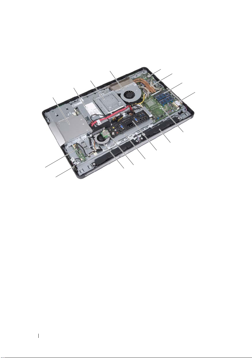
Inside View of Your Computer
15
16
1
2
3
6
7
12
8
4
13
11
9
10
14
5
1 optical-drive assembly 2 power-supply unit
3 hard-drive assembly 4 processor heat-sink fan
5 coin-cell battery 6 processor heat-sink
7 memory module(s) 8 wireless Mini-Card
9 system board 10 speakers (2)
11 I/O cover 12 I/O board shield
13 B-CAS card 14 power-supply fan
15 power-button board 16 converter board
16 Technical Overview
Page 17
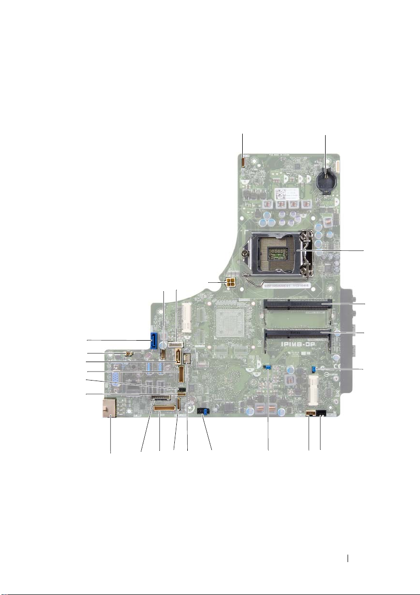
System Board Components
15
21
17
24
8
20
1 2
3
5
11
9
12
13
14
22
10
6
23
19
18
16
4
7
Technical Overview 17
Page 18

1 camera cable connector (WEBCAM) 2 battery socket (BAT1)
3 processor socket (PROCESSOR) 4 memory-module connector
(CHANNEL A DIMM 1)
5 memory-module connector
(CHANNEL A DIMM 0)
7 left speaker cable connector
(LINE_OUT)
9 password reset jumper (E49) 10 SPI connector (E16)
11 processor heat-sink fan cable
connector (CPU FAN)
13 I/O board cable connector (LVDS1) 14 converter board cable connector
15 main power-supply cable connector
(CON5171) (CN3111)
17 infrared cable connector (CN29) 18 display cable connector (For non-AV
19 SATA connector (SATA1) 20 power-supply fan cable connector
21 SATA connector (CON5141) 22 power cable connector (P161)
23 power cable connector (P160) 24 processor power-supply cable
6 CMOS reset jumper (SW50)
8 right speaker cable connector
(LINE_OUT)
12 power-button board cable connector
(FRONT_PANEL)
(INVERTER)
16 touchscreen board cable connector
board) (P170)
(P10)
connector (CON5176)
18 Technical Overview
Page 19
Stand
1
2
WARNING: Before working inside your computer, read the safety information that
shipped with your computer and follow the steps in "Before You Begin" on page 11.
For additional safety best practices information, see the Regulatory Compliance
Homepage at dell.com/regulatory_compliance.
Removing the Stand
Procedure
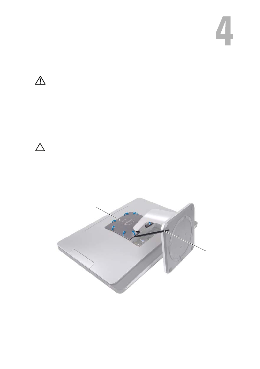
CAUTION: Before opening your computer, ensure that you place the computer
on a soft cloth or clean surface to avoid any scratches on the display.
1
Place the computer face down on a flat surface.
2
Using a plastic scribe, release the stand cover starting from the bottom
of your computer.
1 stand cover 2 plastic scribe
Stand 19
Page 20
3
1
2
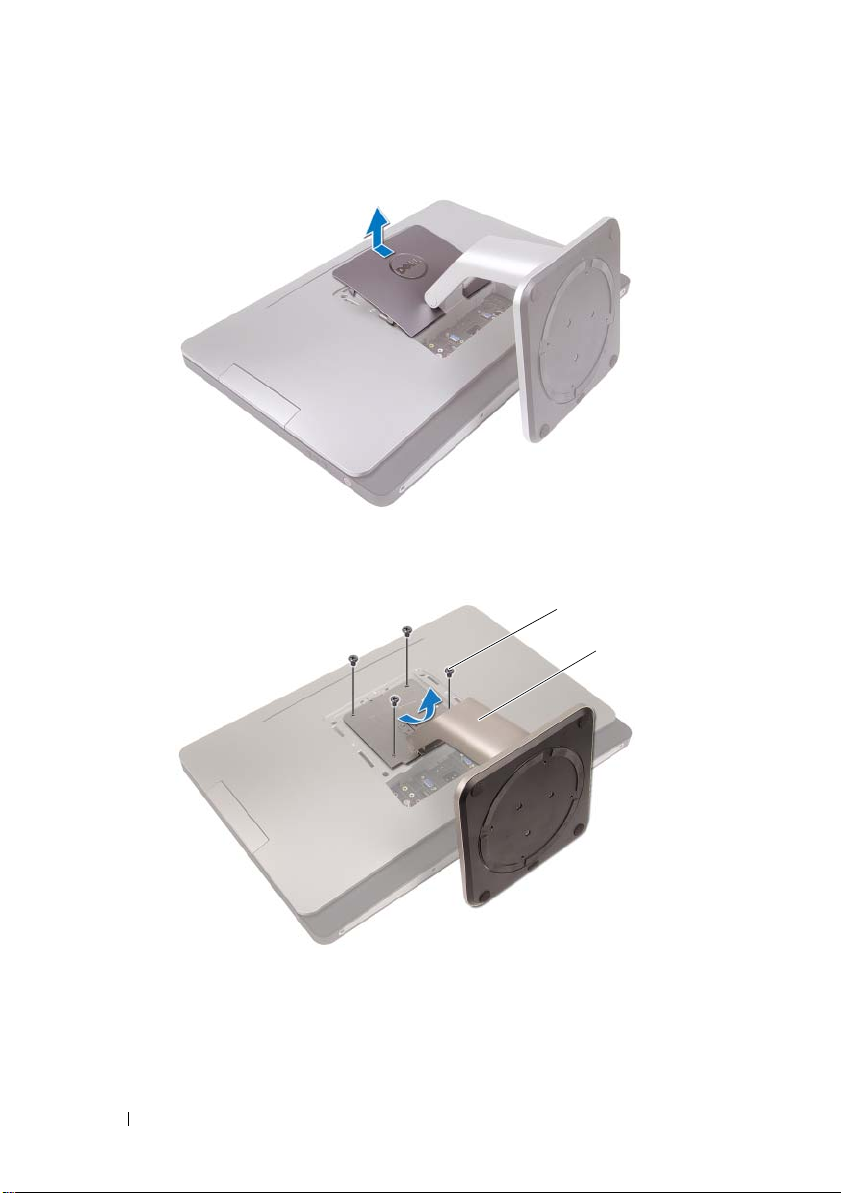
Slide and lift the stand cover off your computer.
4
Remove the screws that secure the stand to your computer.
5 Pivot the stand upward and remove the stand off your computer.
1 screws (4) 2 stand
20 Stand
Page 21

Replacing the Stand
Procedure
1
Align the screw holes on the stand with the screw holes on your computer.
2
Replace the screws that secure the stand to your computer.
3
Slide the stand cover and snap it into place.
4
Follow the instructions in "After Working Inside Your Computer" on page 13.
Stand 21
Page 22

22 Stand
Page 23
Back Cover
2
3
1
4
WARNING: Before working inside your computer, read the safety information that
shipped with your computer and follow the steps in "Before You Begin" on page 11.
For additional safety best practices information, see the Regulatory Compliance
Homepage at dell.com/regulatory_compliance.
Removing the Back Cover
Prerequisites
1
Remove the stand. See "Removing the Stand" on page 19.
Procedure
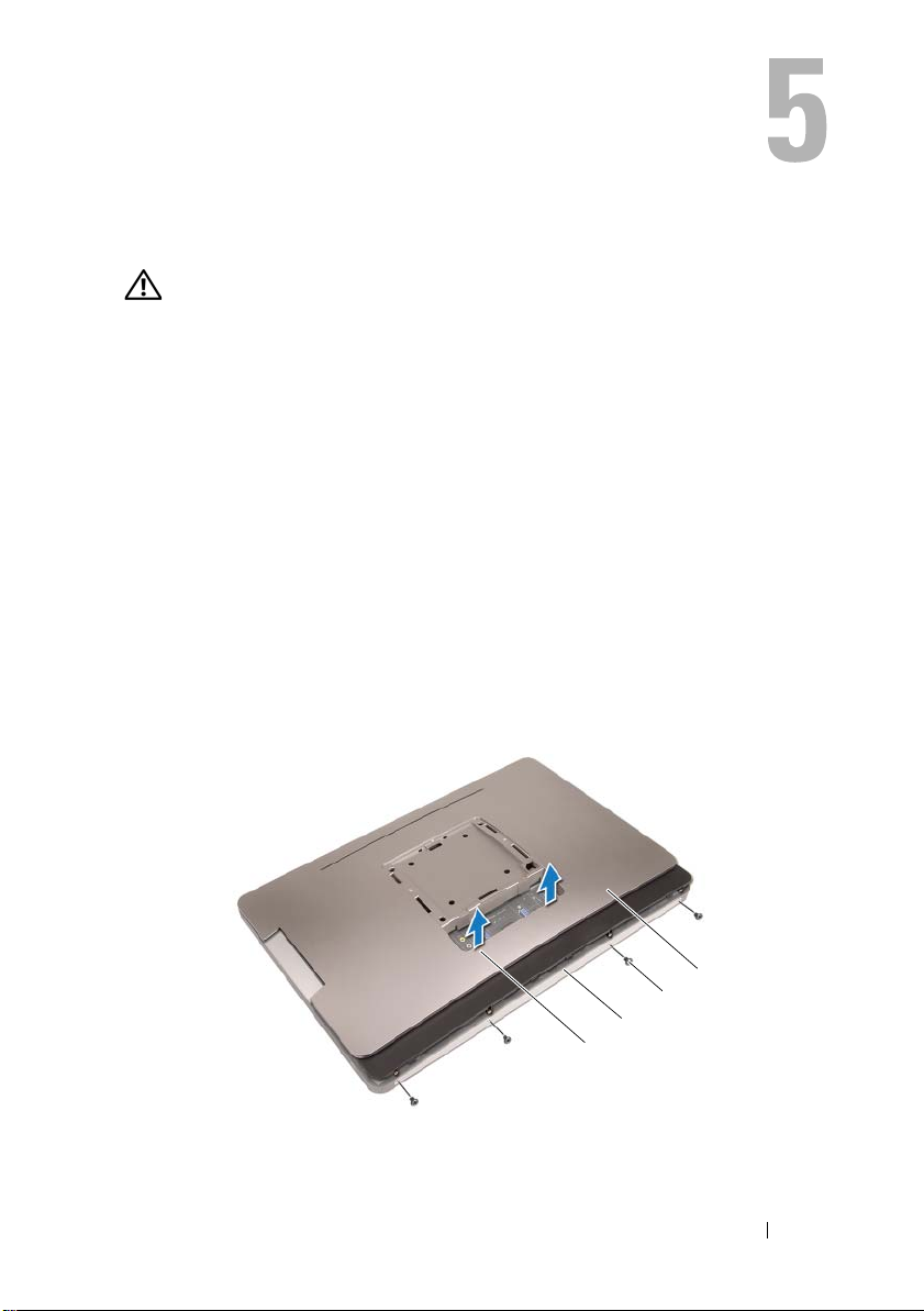
1
Remove the screws that secure the back cover to your computer.
2
Insert your finger into the slots on the back cover, and lift the back cover to
release it from the middle frame.
3
Lift the back cover off your computer.
1 slots (2) 2 middle frame
3 screws (4) 4 back cover
Back Cover 23
Page 24

Replacing the Back Cover
Procedure
1
Place the back cover on your computer and snap it into place.
2
Ensure that the screw holes on the back cover align with the screw holes on
the middle frame.
3
Replace the screws that secure the back cover to your computer.
Postrequisites
1
Replace the stand. See "Replacing the Stand" on page 21.
2
Follow the instructions in "After Working Inside Your Computer" on page 13.
24 Back Cover
Page 25

B-CAS Card
WARNING: Before working inside your computer, read the safety information that
shipped with your computer and follow the steps in "Before You Begin" on page 11.
For additional safety best practices information, see the Regulatory Compliance
Homepage at dell.com/regulatory_compliance.
Removing the B-CAS Card
Prerequisites
1
Remove the stand. See "Removing the Stand" on page 19.
2
Remove the back cover. See "Removing the Back Cover" on page 23.
B-CAS Card 25
Page 26
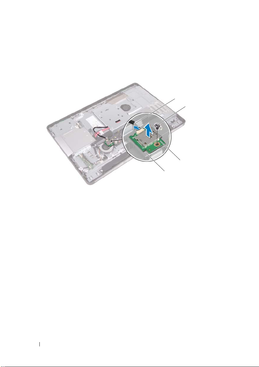
Procedure
4
3
2
1
1
Disconnect the B-CAS card cable from the connector on the B-CAS card.
2
Remove the screw that secures the BCAS-card to the I/O cover.
3
Lift the B-CAS card off the I/O cover.
1 I/O cover 2 B-CAS card
3 screw 4 B-CAS card cable
26 B-CAS Card
Page 27

Replacing the B-CAS card
Procedure
1
Align the screw hole on the B-CAS card with the screw hole on
the I/O cover.
2
Replace the screw that secures the B-CAS card to the I/O cover.
3
Connect the B-CAS card cable to the connector on the B-CAS card.
Postrequisites
1
Replace the back cover. See "Replacing the Back Cover" on page 24.
2
Replace the stand. See "Replacing the Stand" on page 21.
3
Follow the instructions in "After Working Inside Your Computer" on page 13.
B-CAS Card 27
Page 28

28 B-CAS Card
Page 29

Converter Board
WARNING: Before working inside your computer, read the safety information that
shipped with your computer and follow the steps in "Before You Begin" on page 11.
For additional safety best practices information, see the Regulatory Compliance
Homepage at dell.com/regulatory_compliance.
Removing the Converter Board
Prerequisites
1
Remove the stand. See "Removing the Stand" on page 19.
2
Remove the back cover. See "Removing the Back Cover" on page 23.
Converter Board 29
Page 30
Procedure
4
2
3
1
1
Disconnect the converter-board cable and display-backlight cable from the
connectors on the convertor board.
2
Remove the screws that secure the converter board to the chassis.
3
Remove the converter board off the chassis.
1 display-backlight cable 2 converter board
3 screws (2) 4 converter-board cable
30 Converter Board
Page 31

Replacing the Converter Board
Procedure
1
Align the screw holes on the converter board with the screw holes
on the chassis.
2
Replace the screws that secure the converter board to the chassis.
3
Connect the converter-board cable and display-backlight cable to the
connectors on the convertor board.
Postrequisites
1
Replace the back cover. See "Replacing the Back Cover" on page 24.
2
Replace the stand. See "Replacing the Stand" on page 21.
3
Follow the instructions in "After Working Inside Your Computer" on page 13.
Converter Board 31
Page 32

32 Converter Board
Page 33

Power-Button Board
2
3
1
WARNING: Before working inside your computer, read the safety information that
shipped with your computer and follow the steps in "Before You Begin" on page 11.
For additional safety best practices information, see the Regulatory Compliance
Homepage at dell.com/regulatory_compliance.
Removing the Power-Button Board
Prerequisites
1
Remove the stand. See "Removing the Stand" on page 19.
2
Remove the back cover. See "Removing the Back Cover" on page 23.
Procedure
1
Using your fingertips, gently lift the power-button board off
the middle frame.
2
Disconnect the power-button board cable from the connector on the
power-button board.
1 middle frame 2 power-button board
3 power-button board cable
Power-Button Board 33
Page 34

Replacing the Power-Button Board
Procedure
1
Connect the power-button board cable to the connector on the
power-button board.
2
Slide the power-button board into slot on the middle frame.
Postrequisites
1
Replace the back cover. See "Replacing the Back Cover" on page 24.
2
Replace the stand. See "Replacing the Stand" on page 21.
3
Follow the instructions in "After Working Inside Your Computer" on page 13.
34 Power-Button Board
Page 35

Memory Module(s)
1
2
WARNING: Before working inside your computer, read the safety information that
shipped with your computer and follow the steps in "Before You Begin" on page 11.
For additional safety best practices information, see the Regulatory Compliance
Homepage at dell.com/regulatory_compliance.
Removing the Memory Module(s)
Prerequisites
1
Remove the stand. See "Removing the Stand" on page 19.
2
Remove the back cover. See "Removing the Back Cover" on page 23.
Procedure
1
Using your fingertips, lift the memory-module shield to remove it from the
system-board shield.
1 memory-module shield 2 system-board shield
Memory Module(s) 35
Page 36

2
1
3
2
Use your fingertips to carefully spread apart the securing clips on each end
of the memory-module connector until the memory module pops up.
3
Remove the memory module from the memory-module connector.
1 securing clips (2) 2 memory-module connector
3 memory module
36 Memory Module(s)
Page 37

Replacing the Memory Module(s)
Procedure
1
Align the notch on the memory module with the tab on the
memory-module connector.
2
Slide the memory module firmly into the connector at a 45-degree angle,
and press the memory module down until it clicks into place. If you do not
hear the click, remove the memory module and reinstall it.
3
Place the memory-module shield on the system-board shield and snap the
memory-module shield into place.
Postrequisites
1
Replace the back cover. See "Replacing the Back Cover" on page 24.
2
Replace the stand. See "Replacing the Stand" on page 21.
3
Follow the instructions in "After Working Inside Your Computer" on page 13.
Memory Module(s) 37
Page 38

38 Memory Module(s)
Page 39

Optical Drive
WARNING: Before working inside your computer, read the safety information
that shipped with your computer and follow the steps in "Before You Begin" on
page 11. For additional safety best practices information, see the Regulatory
Compliance Homepage at dell.com/regulatory_compliance.
Removing the Optical Drive
Prerequisites
1
Remove the stand. See "Removing the Stand" on page 19.
2
Remove the back cover. See "Removing the Back Cover" on page 23.
Optical Drive 39
Page 40

Procedure
3
2
1
1
Disconnect the power and data cable from the connector on the
optical drive.
2
Remove the screws that secure the optical drive to the chassis.
3
Slide the optical drive and remove it off the chassis.
1 optical drive 2 screws (2)
3 power and data cable
4
Remove the screws that secure the optical-drive bracket to
the optical drive.
5
Remove the optical-drive bracket from the optical drive.
40 Optical Drive
Page 41

6
2
3
1
Pivot the optical-drive bezel upward to release it from the optical drive.
7
Remove the optical-drive bezel from the optical drive.
1 optical-drive bezel 2 optical-drive bracket
3screws (2)
Optical Drive 41
Page 42

Replacing the Optical Drive
Procedure
1
Align the optical-drive bezel with the optical drive and snap it into place.
2
Align the screw holes on the optical-drive bracket with the screw holes on
the optical drive.
3
Replace the screws that secure the optical-drive bracket to
the optical drive.
4
Slide the optical drive into position and ensure that the screw holes on the
optical drive bracket align with the screw holes on the chassis.
5
Replace the screws that secure the optical drive to the chassis.
6
Connect the power and data cable to the connector on the optical drive.
Postrequisites
1
Replace the back cover. See "Replacing the Back Cover" on page 24.
2
Replace the stand. See "Replacing the Stand" on page 21.
3
Follow the instructions in "After Working Inside Your Computer" on page 13.
42 Optical Drive
Page 43

VESA-Mount Bracket
1
2
WARNING: Before working inside your computer, read the safety information that
shipped with your computer and follow the steps in "Before You Begin" on page 11.
For additional safety best practices information, see the Regulatory Compliance
Homepage at dell.com/regulatory_compliance.
Removing the VESA-Mount Bracket
Prerequisites
1
Remove the stand. See "Removing the Stand" on page 19.
2
Remove the back cover. See "Removing the Back Cover" on page 23.
Procedure
1
Remove the screws that secure the VESA-mount bracket to the chassis.
2
Lift the VESA-mount bracket off the chassis.
1 VESA-mount bracket 2 screws (9)
VESA-Mount Bracket 43
Page 44

Replacing the VESA-Mount Bracket
Procedure
1
Align the screw holes on the VESA-mount bracket with the screw holes
on the chassis.
2
Replace the screws that secure the VESA-mount bracket to the chassis.
Postrequisites
1
Replace the back cover. See "Replacing the Back Cover" on page 24.
2
Replace the stand. See "Replacing the Stand" on page 21.
3
Follow the instructions in "After Working Inside Your Computer" on page 13.
44 VESA-Mount Bracket
Page 45

Hard Drive
WARNING: Before working inside your computer, read the safety information
that shipped with your computer and follow the steps in "Before You Begin" on
page 11. For additional safety best practices information, see the Regulatory
Compliance Homepage at dell.com/regulatory_compliance.
CAUTION: To avoid data loss, do not remove the hard drive while the computer
is On or in Sleep state.
CAUTION: Hard drives are extremely fragile. Exercise care when handling
the hard drive.
Removing the Hard Drive
Prerequisites
1
Remove the stand. See "Removing the Stand" on page 19.
2
Remove the back cover. See "Removing the Back Cover" on page 23.
3
Remove the VESA-mount bracket.
See "Removing the VESA-Mount Bracket" on page 43.
Hard Drive 45
Page 46

Procedure
7
3
6
5
4
2
1
1
Remove the optical drive's power and data cable and the B-CAS card cable
from the routing guides on the hard-drive cage.
2
Disconnect the power and data cable from the connector on
the hard drive.
3
Remove the power-supply cable from the routing guide on the
hard drive cage.
4
Remove the screw that secures the hard-drive cage to the chassis.
5
Slide the hard-drive cage toward the top of your computer and remove
the hard-drive cage off the chassis.
1 power-supply cable 2 power and data cable (hard drive)
3 routing guide 4 power and date cable (optical drive)
5 B-CAS card cable 6 screw
7 hard-drive cage
46 Hard Drive
Page 47

6
2
3
1
Remove the screws that secure the hard-drive cage to the hard drive.
7
Slide the hard drive out of the hard-drive cage.
1 hard drive 2 screws (4)
3 hard-drive cage
Hard Drive 47
Page 48

Replacing the Hard Drive
Procedure
1
Slide the hard drive into the hard-drive cage.
2
Align the screw holes on the hard-drive cage with the screw holes on
the hard drive.
3
Replace the screws that secure the hard-drive cage to the hard drive.
4
Place the hard-drive cage on the chassis and slide it toward the bottom of
your computer. Ensure that the tabs at the bottom of the hard-drive cage
slide into the slots on the chassis.
5
Route the power-supply cable through the routing guide on
the hard-drive cage.
6
Route the optical drive's power and data cable and the B-CAS card cable
through the routing guides on the hard-drive cage.
7
Route the hard-drive’s power and data cable through the routing guide on
the hard-drive cage.
8
Connect the power and data cable to the connector on the hard drive.
Postrequisites
1
Replace the VESA-mount bracket.
See "Replacing the VESA-Mount Bracket" on page 44.
2
Replace the back cover. See "Replacing the Back Cover" on page 24.
3
Replace the stand. See "Replacing the Stand" on page 21.
4
Follow the instructions in "After Working Inside Your Computer" on page 13.
48 Hard Drive
Page 49

System-Board Shield
WARNING: Before working inside your computer, read the safety information that
shipped with your computer and follow the steps in "Before You Begin" on page 11.
For additional safety best practices information, see the Regulatory Compliance
Homepage at dell.com/regulatory_compliance.
Removing the System-Board Shield
Prerequisites
1
Remove the stand. See "Removing the Stand" on page 19.
2
Remove the back cover. See "Removing the Back Cover" on page 23.
3
Remove the VESA-mount bracket.
See "Removing the VESA-Mount Bracket" on page 43.
System-Board Shield 49
Page 50

Procedure
2
1
1
Remove the screws that secure the system-board shield to the chassis.
2
Turn the system-board shield to the side of your computer and then release
the system-board shield off the chassis.
1 system-board shield 2 screws (4)
50 System-Board Shield
Page 51

Replacing the System-Board Shield
Procedure
1
Align the screw holes on the system-board shield with the screw holes
on the chassis.
2
Replace the screws that secure the system-board shield to the chassis.
Postrequisites
1
Replace the VESA-mount bracket.
See "Replacing the VESA-Mount Bracket" on page 44.
2
Replace the back cover. See "Replacing the Back Cover" on page 24.
3
Replace the stand. See "Replacing the Stand" on page 21.
4
Follow the instructions in "After Working Inside Your Computer" on page 13.
System-Board Shield 51
Page 52

52 System-Board Shield
Page 53

TV Tuner Card
WARNING: Before working inside your computer, read the safety information that
shipped with your computer and follow the steps in "Before You Begin" on page 11.
For additional safety best practices information, see the Regulatory Compliance
Homepage at dell.com/regulatory_compliance.
Removing the TV Tuner Card
Prerequisites
1
Remove the stand. See "Removing the Stand" on page 19.
2
Remove the back cover. See "Removing the Back Cover" on page 23.
3
Remove the VESA-mount bracket.
See "Removing the VESA-Mount Bracket" on page 43.
4
Remove the system-board shield.
See "Removing the System-Board Shield" on page 49.
TV Tuner Card 53
Page 54

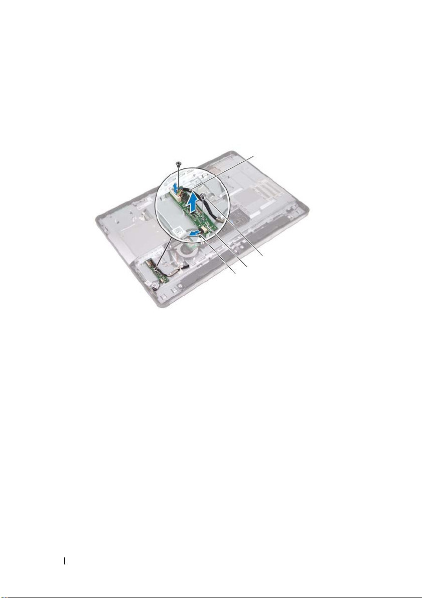
Procedure
1
3
2
4
1
Disconnect the antenna cable from the connector on the TV tuner card.
2
Remove the screws that secure the TV tuner card to the chassis.
3
For Japan only: disconnect the B-CAS card cable from the connector on
the TV tuner card.
1 screws (2) 2 TV tuner card
3 antenna cable 4 B-CAS card cable
54 TV Tuner Card
Page 55

4
1
2
Slide and remove the TV tuner card out of the system-board connector.
1 TV tuner card 2 system-board connector
TV Tuner Card 55
Page 56

Replacing the TV Tuner Card
Procedure
1
Align the notch on the TV tuner card with the tab on the
system-board connector.
2
Insert the TV tuner card connector at a 45-degree angle into the
system-board connector.
3
Press the other end of the TV tuner card down into the slot on the
system board and replace the screws that secure the TV tuner card to
the system-board connector.
4
Connect the antenna cable to the connector on the TV tuner card.
5
For Japan only: connect the B-CAS card cable to the connector on
the TV tuner card.
Postrequisites
1
Replace the system-board shield.
See "Replacing the System-Board Shield" on page 51.
2
Replace the VESA-mount bracket.
See "Replacing the VESA-Mount Bracket" on page 44.
3
Replace the back cover. See "Replacing the Back Cover" on page 24.
4
Replace the stand. See "Replacing the Stand" on page 21.
5
Follow the instructions in "After Working Inside Your Computer" on page 13.
56 TV Tuner Card
Page 57

Wireless Mini-Card
WARNING: Before working inside your computer, read the safety information that
shipped with your computer and follow the steps in "Before You Begin" on page 11.
For additional safety best practices information, see the Regulatory Compliance
Homepage at dell.com/regulatory_compliance.
NOTE: Dell does not guarantee compatibility or provide support for Mini-Cards
from sources other than Dell.
If you ordered a wireless Mini-Card with your computer, the card is
already installed.
Your computer has one half Mini-Card slot which supports a Wireless Local
Area Network (WLAN) + Bluetooth combo card.
Removing the Wireless Mini-Card
Prerequisites
1
Remove the stand. See "Removing the Stand" on page 19.
2
Remove the back cover. See "Removing the Back Cover" on page 23.
3
Remove the VESA-mount bracket.
See "Removing the VESA-Mount Bracket" on page 43.
4
Remove the system-board shield.
See "Removing the System-Board Shield" on page 49.
CAUTION: When the Mini-Card is not in the computer, store it in protective
antistatic packaging. For more information, see "Protecting Against Electrostatic
Discharge" in the safety information that shipped with your computer.
Wireless Mini-Card 57
Page 58

Procedure
1
2
2
1
1
Disconnect the antenna cables from the connectors on the Mini-Card
2
Remove the screws that secure the Mini-Card to the
system-board connector.
1 screws (2) 2 antenna cables (2)
3
Slide and remove the Mini-Card out of the system-board connector.
1 system-board connector 2 Mini-Card
58 Wireless Mini-Card
Page 59

Replacing the Wireless Mini-Card
Procedure
1
Align the notch on the Mini-Card with the tab on the
system-board connector.
CAUTION: Use firm and even pressure to slide the Mini-Card into place. If you
use excessive force, you may damage the connector.
CAUTION: The connectors are keyed to ensure correct insertion. If you feel
resistance, check the connectors on the Mini-Card and on the system board,
and realign the Mini-Card.
CAUTION: To avoid damage to the Mini-Card, never place cables under
the Mini-Card.
2
Insert the Mini-Card connector at a 45-degree angle into the
system-board connector.
3
Press the other end of the Mini-Card down into the slot on the
system board and replace the screws that secure the Mini-Card to
the system-board connector.
4
Connect the antenna cables to the connectors on the Mini-Card.
The following table provides the antenna cable color scheme for the
Mini-Card supported by your computer.
Connectors on the Mini-Card Antenna Cable Color Scheme
WLAN + Bluetooth (2 cables)
Main WLAN + Bluetooth (white triangle)
Auxiliary WLAN + Bluetooth (black triangle)
white
black
Postrequisites
1
Replace the system-board shield.
See "Replacing the System-Board Shield" on page 51.
2
Replace the VESA-mount bracket.
See "Replacing the VESA-Mount Bracket" on page 44.
Wireless Mini-Card 59
Page 60

3
Replace the back cover. See "Replacing the Back Cover" on page 24.
4
Replace the stand. See "Replacing the Stand" on page 21.
5
Follow the instructions in "After Working Inside Your Computer" on page 13.
60 Wireless Mini-Card
Page 61

Speakers
WARNING: Before working inside your computer, read the safety information that
shipped with your computer and follow the steps in "Before You Begin" on page 11.
For additional safety best practices information, see the Regulatory Compliance
Homepage at dell.com/regulatory_compliance.
Removing the Speakers
Prerequisites
1
Remove the stand. See "Removing the Stand" on page 19.
2
Remove the back cover. See "Removing the Back Cover" on page 23.
3
Remove the VESA-mount bracket.
See "Removing the VESA-Mount Bracket" on page 43.
4
Remove the system-board shield.
See "Removing the System-Board Shield" on page 49.
Speakers 61
Page 62

Procedure
1
2
4
3
1
Disconnect the left and right speaker cables from the
system-board connectors.
2
Remove the speaker cables from the routing guides on the chassis.
3
Remove the screws that secure the speakers to the chassis.
4
Lift the speakers off the chassis.
1 screws (4) 2 speakers (2)
3 right-speaker cable connector 4 left-speaker cable connector
62 Speakers
Page 63

Replacing the Speakers
Procedure
1
Align the screw holes on the speakers with the screw holes on the chassis
2
Replace the screws that secure the speakers to the chassis.
3
Route the speaker cables through the routing guides on the chassis.
4
Connect the left and right speaker cables to the system-board connectors.
Postrequisites
1
Replace the system-board shield.
See "Replacing the System-Board Shield" on page 51.
2
Replace the VESA-mount bracket.
See "Replacing the VESA-Mount Bracket" on page 44.
3
Replace the back cover. See "Replacing the Back Cover" on page 24.
4
Replace the stand. See "Replacing the Stand" on page 21.
5
Follow the instructions in "After Working Inside Your Computer" on page 13.
Speakers 63
Page 64

64 Speakers
Page 65

Processor Heat-Sink
WARNING: Before working inside your computer, read the safety information that
shipped with your computer and follow the steps in "Before You Begin" on page 11.
For additional safety best practices information, see the Regulatory Compliance
Homepage at dell.com/regulatory_compliance.
Removing the Processor Heat-Sink
Prerequisites
1
Remove the stand. See "Removing the Stand" on page 19.
2
Remove the back cover. See "Removing the Back Cover" on page 23.
3
Remove the VESA-mount bracket.
See "Removing the VESA-Mount Bracket" on page 43.
4
Remove the system-board shield.
See "Removing the System-Board Shield" on page 49.
Processor Heat-Sink 65
Page 66

Procedure
1
3
4
2
1
Remove the screw that secures the processor heat-sink to the chassis.
2
In sequential order (indicated on the processor heat-sink), loosen the
captive screws that secure the processor heat-sink to the system board.
3
Peel the portion of the aluminum foil that is adhered over the
processor heat-sink fan.
4
Lift the processor heat-sink off the system board.
1 screw 2 aluminum foil
3 processor heat-sink 4 captive screws (4)
66 Processor Heat-Sink
Page 67

Replacing the Processor Heat-Sink
Procedure
NOTE: The original thermal grease can be reused, if the original system board
and heat sink are reinstalled together. If either the system board or the heat sink
is replaced, use the thermal pad provided in the kit to ensure that thermal
conductivity is achieved.
1
Clean the thermal grease from the bottom of the processor heat-sink
and reapply it.
2
Align the screw holes on the processor heat-sink with the screw holes on
the system board.
3
In sequential order (indicated on the processor heat-sink), tighten the
captive screws that secure the processor heat-sink to the system board.
4
Replace the screw that secures the processor heat-sink to the chassis.
5
Adhere the aluminum foil on the processor heat-sink over the
processor heat-sink fan.
Postrequisites
1
Replace the system-board shield.
See "Replacing the System-Board Shield" on page 51.
2
Replace the VESA-mount bracket.
See "Replacing the VESA-Mount Bracket" on page 44.
3
Replace the back cover. See "Replacing the Back Cover" on page 24.
4
Replace the stand. See "Replacing the Stand" on page 21.
5
Follow the instructions in "After Working Inside Your Computer" on page 13.
Processor Heat-Sink 67
Page 68

68 Processor Heat-Sink
Page 69

Processor Heat-Sink Fan
WARNING: Before working inside your computer, read the safety information that
shipped with your computer and follow the steps in "Before You Begin" on page 11.
For additional safety best practices information, see the Regulatory Compliance
Homepage at dell.com/regulatory_compliance.
Removing the Processor Heat-Sink Fan
Prerequisites
1
Remove the stand. See "Removing the Stand" on page 19.
2
Remove the back cover. See "Removing the Back Cover" on page 23.
3
Remove the VESA-mount bracket.
See "Removing the VESA-Mount Bracket" on page 43.
4
Remove the system-board shield.
See "Removing the System-Board Shield" on page 49.
Processor Heat-Sink Fan 69
Page 70

Procedure
3
4
1
2
1
Disconnect the processor heat-sink fan cable from the
system-board connector.
2
Remove the screws that secure the processor heat-sink fan to the chassis.
3
Peel the portion of the aluminum foil that is adhered over the
processor heat-sink.
4
Lift the processor heat-sink fan off the chassis
1 aluminum foil 2 processor heat-sink fan
3 screws (3) 4 processor heat-sink fan cable
70 Processor Heat-Sink Fan
Page 71

Replacing the Processor Heat-Sink Fan
Procedure
1
Align the screw holes on the processor heat-sink fan with the screw holes
on the chassis.
2
Replace the screws that secure the processor heat-sink fan to the chassis.
3
Connect the processor heat-sink fan cable to the system-board connector.
4
Adhere the aluminum foil on the processor heat-sink fan over the
processor heat-sink.
Postrequisites
1
Replace the system-board shield.
See "Replacing the System-Board Shield" on page 51.
2
Replace the VESA-mount bracket.
See "Replacing the VESA-Mount Bracket" on page 44.
3
Replace the back cover. See "Replacing the Back Cover" on page 24.
4
Replace the stand. See "Replacing the Stand" on page 21.
5
Follow the instructions in "After Working Inside Your Computer" on page 13.
Processor Heat-Sink Fan 71
Page 72

72 Processor Heat-Sink Fan
Page 73

Processor
WARNING: Before working inside your computer, read the safety information that
shipped with your computer and follow the steps in "Before You Begin" on page 11.
For additional safety best practices information, see the Regulatory Compliance
Homepage at dell.com/regulatory_compliance.
Removing the Processor
Prerequisites
1
Remove the stand. See "Removing the Stand" on page 19.
2
Remove the back cover. See "Removing the Back Cover" on page 23.
3
Remove the VESA-mount bracket.
See "Removing the VESA-Mount Bracket" on page 43.
4
Remove the system-board shield.
See "Removing the System-Board Shield" on page 49.
5
Remove the processor heat-sink.
See "Removing the Processor Heat-Sink" on page 65.
Processor 73
Page 74

Procedure
3
1
4
2
1
Press the release lever down on the processor cover and then pull it
outwards to release it from the tab that secures it.
2
Extend the release lever completely to open the processor cover.
Leave the release lever extended in the release position so that the socket is
ready for the new processor.
3
Gently lift the processor to remove it from the socket.
1 release lever 2 tab
3 processor cover 4 processor
74 Processor
Page 75

Replacing the Processor
5
3
1
2
4
6
Procedure
1
Unpack the new processor, being careful not to touch the underside
of the processor.
CAUTION: Ground yourself by touching an unpainted metal surface.
CAUTION: You must position the processor correctly in the processor socket to
avoid permanent damage to the processor.
2
If the release lever on the socket is not fully extended, move it to
that position.
3
Orient the alignment notches on the processor with the alignment tabs
on the socket.
4
Align the pin-1 corners of the processor and socket, and then place the
processor in the processor socket. Set the processor lightly in the socket
and ensure that the processor is positioned correctly.
CAUTION: Ensure that the processor cover notch is positioned underneath the
alignment post.
5
When the processor is fully seated in the socket, close the processor cover.
6
Pivot the release lever down and place it under the tab on
the processor cover.
1 processor pin-1 indicator 2 processor
3 alignment notches (2) 4 alignment post
5 processor cover 6 release lever
Processor 75
Page 76

7
Clean the thermal grease from the bottom of the heat sink.
8
Apply the new thermal grease to the top of the processor.
CAUTION: Ensure that you apply new thermal grease. The new thermal grease is
critical for ensuring adequate thermal bonding, which is a requirement for
optimal processor operation.
Postrequisites
1
Replace the processor heat-sink.
See "Replacing the Processor Heat-Sink" on page 67.
2
Replace the system-board shield.
See "Replacing the System-Board Shield" on page 51.
3
Replace the VESA-mount bracket.
See "Replacing the VESA-Mount Bracket" on page 44.
4
Replace the back cover. See "Replacing the Back Cover" on page 24.
5
Replace the stand. See "Replacing the Stand" on page 21.
6
Follow the instructions in "After Working Inside Your Computer" on page 13.
76 Processor
Page 77

Power-Supply Fan Bracket
WARNING: Before working inside your computer, read the safety information that
shipped with your computer and follow the steps in "Before You Begin" on page 11.
For additional safety best practices information, see the Regulatory Compliance
Homepage at dell.com/regulatory_compliance.
Removing the Power-Supply Fan Bracket
Prerequisites
1
Remove the stand. See "Removing the Stand" on page 19.
2
Remove the back cover. See "Removing the Back Cover" on page 23.
Power-Supply Fan Bracket 77
Page 78

Procedure
1
3
2
1
Disconnect the B-CAS card cable from the connector on the B-CAS card.
2
Remove the screw that secures the power-supply fan bracket to the chassis.
3
Lift the power-supply fan bracket off the chassis.
1 screw 2 power-supply fan bracket
3 B-CAS card cable
78 Power-Supply Fan Bracket
Page 79

Replacing the Power-Supply Fan Bracket
Procedure
1
Align the screw hole on the power-supply fan bracket with the screw hole
on the chassis.
2
Replace the screw that secures the power-supply fan bracket to the chassis.
3
Connect the B-CAS card cable to the connector on the B-CAS card.
Postrequisites
1
Replace the back cover. See "Replacing the Back Cover" on page 24.
2
Replace the stand. See "Replacing the Stand" on page 21.
3
Follow the instructions in "After Working Inside Your Computer" on page 13.
Power-Supply Fan Bracket 79
Page 80

80 Power-Supply Fan Bracket
Page 81

I/O Cover
WARNING: Before working inside your computer, read the safety information that
shipped with your computer and follow the steps in "Before You Begin" on page 11.
For additional safety best practices information, see the Regulatory Compliance
Homepage at dell.com/regulatory_compliance.
Removing the I/O Cover
Prerequisites
1
Remove the stand. See "Removing the Stand" on page 19.
2
Remove the back cover. See "Removing the Back Cover" on page 23.
3
Remove the B-CAS card. See "Removing the B-CAS Card" on page 25.
I/O Cover 81
Page 82

Procedure
1
Gently lift the I/O cover to release it from the tabs that secure it
to the chassis.
1I/O cover
82 I/O Cover
Page 83

Replacing the I/O Cover
Procedure
Place the I/O cover over the I/O board shield and snap it into position.
Postrequisites
1
Replace the B-CAS card. See "Replacing the B-CAS card" on page 27.
2
Replace the back cover. See "Replacing the Back Cover" on page 24.
3
Replace the stand. See "Replacing the Stand" on page 21.
4
Follow the instructions in "After Working Inside Your Computer" on page 13.
I/O Cover 83
Page 84

84 I/O Cover
Page 85

I/O Board Shield
WARNING: Before working inside your computer, read the safety information that
shipped with your computer and follow the steps in "Before You Begin" on page 11.
For additional safety best practices information, see the Regulatory Compliance
Homepage at dell.com/regulatory_compliance.
Removing the I/O Board Shield
Prerequisites
1
Remove the stand. See "Removing the Stand" on page 19.
2
Remove the back cover. See "Removing the Back Cover" on page 23.
3
Remove the VESA-mount bracket.
See "Removing the VESA-Mount Bracket" on page 43.
4
Remove the system-board shield.
See "Removing the System-Board Shield" on page 49.
5
Remove the power-supply fan bracket.
See "Removing the Power-Supply Fan Bracket" on page 77.
6
Remove the B-CAS card. See "Removing the B-CAS Card" on page 25.
7
Remove the I/O cover. See "Removing the I/O Cover" on page 81.
I/O Board Shield 85
Page 86

Procedure
4
1
2
3
1
Remove the screws that secure the power port to the I/O board shield.
2
Remove the screw that secures the power supply control board to the
I/O board shield.
3
Remove the screws that secure the I/O board shield to the chassis.
4
Turn the I/O board shield over and place it on the hard-drive cage.
1 power-supply control board 2 screws (7)
3 power port 4 I/O board shield
86 I/O Board Shield
Page 87

5
3
5
4
1
2
Slide the power port and power-supply control board through the slot on
the I/O board shield.
6
Disconnect the power-supply fan cable and infrared cable from the
system-board connectors.
7
Disconnect the antenna cable from the connector on the TV tuner card.
8
Lift the I/O board shield off the chassis.
1 I/O board shield 2 TV tuner card
3 antenna cable 4 infrared cable
5 power-supply fan cable
I/O Board Shield 87
Page 88

Replacing the I/O Board Shield
Procedure
1
Connect the power-supply fan cable and infrared cable to the
system-board connectors.
2
Connect the antenna cable to the connector on the TV tuner card.
3
Slide the power port and the power-supply control board through the slot
on the I/O board shield.
4
Align the screw holes on the I/O board shield with the screw holes
on the chassis.
5
Replace the screws that secure the I/O board shield to the chassis.
6
Replace the screw that secures the power-supply control board to the
I/O board shield.
7
Replace the screws that secure the power port to the I/O board shield.
Postrequisites
1
Replace the I/O cover. See "Replacing the I/O Cover" on page 83.
2
Replace the B-CAS card. See "Replacing the B-CAS card" on page 27.
3
Replace the power-supply fan bracket.
See "Replacing the Power-Supply Fan Bracket" on page 79.
4
Replace the system-board shield.
See "Replacing the System-Board Shield" on page 51.
5
Replace the VESA-mount bracket.
See "Replacing the VESA-Mount Bracket" on page 44.
6
Replace the back cover. See "Replacing the Back Cover" on page 24.
7
Replace the stand. See "Replacing the Stand" on page 21.
8
Follow the instructions in "After Working Inside Your Computer" on page 13.
88 I/O Board Shield
Page 89

Power-Supply Unit
WARNING: Before working inside your computer, read the safety information that
shipped with your computer and follow the steps in "Before You Begin" on page 11.
For additional safety best practices information, see the Regulatory Compliance
Homepage at dell.com/regulatory_compliance.
Removing the Power-Supply Unit
Prerequisites
1
Remove the stand. See "Removing the Stand" on page 19.
2
Remove the back cover. See "Removing the Back Cover" on page 23.
3
Remove the VESA-mount bracket.
See "Removing the VESA-Mount Bracket" on page 43.
4
Remove the system-board shield.
See "Removing the System-Board Shield" on page 49.
5
Remove the power-supply fan bracket.
See "Removing the Power-Supply Fan Bracket" on page 77.
6
Remove the B-CAS card. See "Removing the B-CAS Card" on page 25.
7
Remove the I/O cover. See "Removing the I/O Cover" on page 81.
8
Remove the I/O board shield.
See "Removing the I/O Board Shield" on page 85.
Power-Supply Unit 89
Page 90

Procedure
2
5
3
4
1
1
Disconnect the main power cable and processor power cable from the
connectors on the system board.
2
Remove the main power cable and processor power cable from the
routing guides on the chassis.
3
Remove the power-supply port cable from the routing guides
on the chassis.
4
Remove the screws that secure the power-supply unit to the chassis.
5
Lift the power-supply unit off the chassis.
1 screws (4) 2 power-port cable
3 power-supply unit 4 main power cable
5 processor power cable
90 Power-Supply Unit
Page 91

Replacing the Power-Supply Unit
Procedure
1
Align the screw holes on the power-supply unit with the screw holes
on the chassis.
2
Replace the screws that secure the power-supply unit to the chassis.
3
Route the power-supply port cable through the routing guides
on the chassis.
4
Route the main power cable and processor power cable through the
routing guides on the chassis.
5
Connect the main power cable and processor power cable to the
connectors on the system board.
Postrequisites
1
Replace the I/O board shield.
See "Replacing the I/O Board Shield" on page 88.
2
Replace the I/O cover. See "Replacing the I/O Cover" on page 83.
3
Replace the B-CAS card. See "Replacing the B-CAS card" on page 27.
4
Replace the power-supply fan bracket.
See "Replacing the Power-Supply Fan Bracket" on page 79.
5
Replace the system-board shield.
See "Replacing the System-Board Shield" on page 51.
6
Replace the VESA-mount bracket.
See "Replacing the VESA-Mount Bracket" on page 44.
7
Replace the back cover. See "Replacing the Back Cover" on page 24.
8
Replace the stand. See "Replacing the Stand" on page 21.
9
Follow the instructions in "After Working Inside Your Computer" on page 13.
Power-Supply Unit 91
Page 92

92 Power-Supply Unit
Page 93

Power-Supply Fan
WARNING: Before working inside your computer, read the safety information that
shipped with your computer and follow the steps in "Before You Begin" on page 11.
For additional safety best practices information, see the Regulatory Compliance
Homepage at dell.com/regulatory_compliance.
Removing the Power-Supply Fan
Prerequisites
1
Remove the stand. See "Removing the Stand" on page 19.
2
Remove the back cover. See "Removing the Back Cover" on page 23.
3
Remove the VESA-mount bracket.
See "Removing the VESA-Mount Bracket" on page 43.
4
Remove the system-board shield.
See "Removing the System-Board Shield" on page 49.
5
Remove the power-supply fan bracket.
See "Removing the Power-Supply Fan Bracket" on page 77.
6
Remove the B-CAS card. See "Removing the B-CAS Card" on page 25.
7
Remove the I/O cover. See "Removing the I/O Cover" on page 81.
8
Remove the I/O board shield.
See "Removing the I/O Board Shield" on page 85.
Power-Supply Fan 93
Page 94

Procedure
1
2
1
Remove the screws that secure the power-supply fan to the
I/O board shield.
2
Lift the power-supply fan off the I/O board shield.
1 power-supply fan 2 screws (2)
94 Power-Supply Fan
Page 95

Replacing the Power-Supply Fan
Procedure
1
Align the screw holes on the power-supply fan with the screw holes on
the I/O board shield.
2
Replace the screws that secure the power-supply fan to the
I/O board shield.
Postrequisites
1
Replace the I/O board shield.
See "Replacing the I/O Board Shield" on page 88.
2
Replace the I/O cover. See "Replacing the I/O Cover" on page 83.
3
Replace the B-CAS card. See "Replacing the B-CAS card" on page 27.
4
Replace the power-supply fan bracket.
See "Replacing the Power-Supply Fan Bracket" on page 79.
5
Replace the system-board shield.
See "Replacing the System-Board Shield" on page 51.
6
Replace the VESA-mount bracket.
See "Replacing the VESA-Mount Bracket" on page 44.
7
Replace the back cover. See "Replacing the Back Cover" on page 24.
8
Replace the stand. See "Replacing the Stand" on page 21.
9
Follow the instructions in "After Working Inside Your Computer" on page 13.
Power-Supply Fan 95
Page 96

96 Power-Supply Fan
Page 97

TV-In Port
WARNING: Before working inside your computer, read the safety information that
shipped with your computer and follow the steps in "Before You Begin" on page 11.
For additional safety best practices information, see the Regulatory Compliance
Homepage at dell.com/regulatory_compliance.
Removing the TV-In Port
Prerequisites
1
Remove the stand. See "Removing the Stand" on page 19.
2
Remove the back cover. See "Removing the Back Cover" on page 23.
3
Remove the VESA-mount bracket.
See "Removing the VESA-Mount Bracket" on page 43.
4
Remove the system-board shield.
See "Removing the System-Board Shield" on page 49.
5
Remove the power-supply fan bracket.
See "Removing the Power-Supply Fan Bracket" on page 77.
6
Remove the B-CAS card. See "Removing the B-CAS Card" on page 25.
7
Remove the I/O cover. See "Removing the I/O Cover" on page 81.
8
Remove the I/O board shield.
See "Removing the I/O Board Shield" on page 85.
TV-In Port 97
Page 98

Procedure
2
1
1
Remove the hex nut that secures the TV-in port to the I/O board shield.
2
Slide the TV-in port along with its cable through the slot on
the I/O board shield.
1 TV-in port 2 hex nut
98 TV-In Port
Page 99

Replacing the TV-In Port
Procedure
1
Slide the TV-in port along with its cable through the slot on the
I/O board shield.
2
Replace the hex nut that secures the TV-in port to the I/O board shield.
Postrequisites
1
Replace the I/O board shield.
See "Replacing the I/O Board Shield" on page 88.
2
Replace the I/O cover. See "Replacing the I/O Cover" on page 83.
3
Replace the B-CAS card. See "Replacing the B-CAS card" on page 27.
4
Replace the power-supply fan bracket.
See "Replacing the Power-Supply Fan Bracket" on page 79.
5
Replace the system-board shield.
See "Replacing the System-Board Shield" on page 51.
6
Replace the VESA-mount bracket.
See "Replacing the VESA-Mount Bracket" on page 44.
7
Replace the back cover. See "Replacing the Back Cover" on page 24.
8
Replace the stand. See "Replacing the Stand" on page 21.
9
Follow the instructions in "After Working Inside Your Computer" on page 13.
TV-In Port 99
Page 100

100 TV-In Port
 Loading...