

Page 1

Dell™ Remote Console Switch
System User’s Guide
Notes, Notices, and Cautions
NOTE: A NOTE indicates important information that helps you make better
use of your computer.
NOTICE: A NOTICE indicates either potential damage to hardware or loss
of data and tells you how to avoid the problem.
CAUTION: A CAUTION indicates a potential for property damage,
personal injury, or death.
___________________
Information in this document is subject to change without notice.
© 2008 Dell Inc. All rights reserved.
2161DS-2/4161DS/2321DS Remote Console Switch
Page 2

Third Party Software. You acknowledge that the SOFTW ARE PRODUCT may contain or be provided
with copyrighted software of Dell's suppliers as identified in associated documentation or other printed
or electronic materials (“Third Party Software”) which are obtained under a license from such
suppliers. Y our use of any such Third Party Software shall be subject to and you agree to comply with
the applicable restrictions and other terms and conditions set forth in such documentation or materials
as set forth in any “Third-Party Licenses ReadMe” file or similar file located in the installation directory
for the SOFTWARE PRODUCT.
Any open source software is distributed in the hope that it will be useful, but is provided “as is” without
any expressed or implied warranty; including but not limited to the implied warranty of merchantablity
or fitness for a particular purpose. In no event shall Dell, the copyright holders, or the contributors be
liable for any direct, indirect, incidental, special, exemplary , or consequential damages (including , but
not limited to, procurement of substitute goods or services; loss of use, data or profits; or business
interruption) however caused and on any theory of liability, whether in contract, strict liability, or tort
(including negligence or otherwise) arising in any way out of the use of this software , even if advised
of the possibility of such damage.
Reproduction of these materials in any manner whatsoever without written permission of Dell Inc. is
strictly forbidden.
Trademarks used in this text: Avocent and Cyclades are registered trademarks of A vocent Corporation.
OSCAR is a registered trademark of Avocent Corporation or its affiliates. Dell, OpenManage, and the
DELL logo are trademarks of Dell Inc.; Active Directory, DirectDraw, Internet Explorer, Microsoft,
Win32, Windows, Windows NT , Windows Server, and W indows V ista are either trademarks or registered
trademarks of Microsoft Corporation in the United States and/or other countries; Intel and Pentium
are registered trademarks of Intel Corporation; Red Hat and Red Hat Enterprise Linux are registered
trademarks of Red Hat, Inc.; SUSE is a registered trademark of Novell Inc. in the United States and
other countries; UNIX is a registered trademark of The Open Group in the United States and other
countries; Sun, Sun Microsystems, and the Sun logo are trademarks or registered trademarks of Sun
Microsystems, Inc. or its subsidiaries in the United States and other countries.
Other trademarks and trade names may be used in this document to refer to either the entities claiming
the marks and names or their products. Dell Inc. disclaims any proprietary interest in trademarks and
trade names other than its own.
590-728-599C/59E-728-599C
October 2008
Model 2161DS-2/4161DS/2321DS Remote Console Switch
Page 3

Safety and EMC Approvals and Markings
• UL / cUL
• CE - EU
•N (Nemko)
•GOST
•C-Tick
•NOM / NYCE
•MIC (BCC)
•SASO
•TUV-GS
•IRAM
•FCC, ICES,
•VCCI
•SoNCAP
•SABS
•Bellis
•FIS/ Kvalitet
•Koncar
•CKT
•INSM
•Ukrtest
•STZ
Safety certifications and EMC certifications for this product are obtained under
one or more of the following designations: CMN (Certification Model
Number), MPN (Manufacturer’s Part Number) or Sales Level Model
designation. The designation that is referenced in the EMC and/or safety
reports and certificates is printed on the label applied to this product.
Please refer to the
Dell Regulatory Technical Bulletin
included with your Remote
Console Switch for more detailed EMC and EA text.
Page 4

Contents
Safety Precautions . . . . . . . . . . . . . . . . . . . . xiv
1 Product Overview . . . . . . . . . . . . . . . . . . 1
Remote Console Switch Features and Benefits. . . . . . 1
. . . . . . . . . . . . . . . . . . . . . . . xiv
General
Rack Mounting of Systems
. . . . . . . . . . . . . xvi
LAN Options. . . . . . . . . . . . . . . . . . . . xvii
SIP Intelligent Module
. . . . . . . . . . . . . . . . 1
Multiplatform Support . . . . . . . . . . . . . . . . 2
Interoperability with Avocent® IQ Module Intelligent
Cabling
. . . . . . . . . . . . . . . . . . . . . . . . 2
OSCAR Interface . . . . . . . . . . . . . . . . . . . 2
On-board Web Interface
DSView® 3 Management Software Plug-in
. . . . . . . . . . . . . . . 2
. . . . . 2
Virtual Media . . . . . . . . . . . . . . . . . . . . . 3
Security
Encryption
. . . . . . . . . . . . . . . . . . . . . . . . 3
. . . . . . . . . . . . . . . . . . . . . . . 3
Operation Modes . . . . . . . . . . . . . . . . . . . 4
Video
. . . . . . . . . . . . . . . . . . . . . . . . . 4
FLASH Upgradeable
. . . . . . . . . . . . . . . . . 4
Cascade (Tier) Expansion. . . . . . . . . . . . . . . 5
iv Contents
Remote Console Switch Software Features and Benefits 5
Easy to Install and Configure
. . . . . . . . . . . . . 5
Powerful Customization Capabilities . . . . . . . . . 6
Extensive Remote Console Switch Management
IPv4 and IPv6 Capabilities
. . . . . . . . . . . . . . 6
. . 6
Page 5

LDAP . . . . . . . . . . . . . . . . . . . . . . . . . 6
Interoperability with Avocent Products
. . . . . . . 6
2 Installation . . . . . . . . . . . . . . . . . . . . . . . . 8
Remote Console Switch Quick Setup Checklist . . . . . 8
Remote Console Switch Installation and Setup
Getting Started
Setting Up Your Network
Keyboards
. . . . . . . . . . . . . . . . . . . 10
. . . . . . . . . . . . . . 11
. . . . . . . . . . . . . . . . . . . . . 11
Rack Mounting Your Remote Console Switch Unit
Installing the Remote Console Switch Unit
Video Optimization
. . . . . . . . . . . . . . . . . 24
. . . . 10
. . . 11
. . . . . 15
Mouse Acceleration . . . . . . . . . . . . . . . . 24
Connecting a SIP
Adding a Cascade Switch
. . . . . . . . . . . . . . . . . . 24
. . . . . . . . . . . . . 26
Cascading with Legacy Switches . . . . . . . . . 29
Adding a PEM (Optional)
Connecting to the Network
On-board Web Interface Installation and Setup
Supported Browsers
Launching the On-board Web Interface
. . . . . . . . . . . . . . 30
. . . . . . . . . . . . . 32
. . . . 32
. . . . . . . . . . . . . . . . 32
. . . . . . 32
Remote Console Switch Software Installation and Setup
Installing the Remote Console Switch Software
. . 34
33
3 Controlling Your System at the Analog
Ports . . . . . . . . . . . . . . . . . . . . . . . . . . . . 36
Viewing and Selecting Ports and Devices . . . . . . . 36
Selecting Devices
. . . . . . . . . . . . . . . . . 38
Contents v
Page 6

Soft Switching . . . . . . . . . . . . . . . . . . . 38
Navigating the OSCAR Interface
. . . . . . . . . . . . . 39
Configuring OSCAR Interface Menus . . . . . . . . . . 41
Changing the Display Behavior
. . . . . . . . . . . 42
Setting Console Security . . . . . . . . . . . . . . 44
Controlling the Status Flag
Setting the Interface Language
. . . . . . . . . . . . . 46
. . . . . . . . . . . 48
Assigning Device Types. . . . . . . . . . . . . . . 48
Assigning Device Names
Configuring Network Settings
Displaying Version Information
Scanning Your System
. . . . . . . . . . . . . . 50
. . . . . . . . . . . 51
. . . . . . . . . . . . . 53
. . . . . . . . . . . . . . . . . . 53
Setting the Preemption Warning . . . . . . . . . . . . 55
Displaying Configuration Information
Running System Diagnostics
. . . . . . . . . . . . . . . 57
. . . . . . . . . . 56
Broadcasting to Servers . . . . . . . . . . . . . . . . . 58
Power Controlling Devices
Power window
PDUs window
. . . . . . . . . . . . . . . 60
. . . . . . . . . . . . . . . . . . . 60
. . . . . . . . . . . . . . . . . . . . 61
PDU Settings window. . . . . . . . . . . . . . . . 61
PDU Inlets window
PDU Outlets window
. . . . . . . . . . . . . . . . . 62
. . . . . . . . . . . . . . . . 63
4 Remote Console Switch Software
Basic Operations . . . . . . . . . . . . . . . . . . . 65
vi Contents
Launching the Remote Console Switch Software. . . . 65
Page 7

Navigating the Remote Console Switch Software . . . 65
Viewing Your System in the Explorer
Explorer Window Features
. . . . . . . . . . . . . 67
. . . . . . . . 66
Adding a Remote Console Switch or Avocent Remote
Console Switch
. . . . . . . . . . . . . . . . . . . . . 68
Accessing Your Remote Console Switch
Launching the VNC or RDP Viewer
. . . . . . . . 75
. . . . . . . . . . . 77
Changing Server and Switch Properties . . . . . . . . 78
Changing General Properties
. . . . . . . . . . . . 78
Changing Server Network Properties . . . . . . . 80
Changing Switch Network Properties
Changing Information Properties
. . . . . . . 81
. . . . . . . . . . 83
Viewing Server Connections Properties . . . . . . 84
VNC properties
RDP properties
. . . . . . . . . . . . . . . . . . . 85
. . . . . . . . . . . . . . . . . . . 87
Accessing a Server via a Browser Window . . . . 89
Changing Server and Switch Options . . . . . . . . . . 89
General options
. . . . . . . . . . . . . . . . . . . 89
HTTP/HTTPS options . . . . . . . . . . . . . . . . 91
VNC options
RDP options
Organizing Your System
Modifying Custom Field Names
Creating Folders
. . . . . . . . . . . . . . . . . . . . . 91
. . . . . . . . . . . . . . . . . . . . . 92
. . . . . . . . . . . . . . . . . 93
. . . . . . . . . . 95
. . . . . . . . . . . . . . . . . . 95
Assigning a Unit to a Site, Location, or Folder . . . 96
Deleting and Renaming . . . . . . . . . . . . . . . . . 97
Customizing the Explorer Window
Modifying the Selected View on Startup
Changing the Default Browser
. . . . . . . . . . . 99
. . . . . . 99
. . . . . . . . . . . 100
Contents vii
Page 8

Managing Your Local Databases . . . . . . . . . . . 100
Saving a Database
Exporting a Database
. . . . . . . . . . . . . . . . 100
. . . . . . . . . . . . . . . 101
Loading a Database. . . . . . . . . . . . . . . . 102
5 Using the Viewer . . . . . . . . . . . . . . . . . . 103
Accessing Servers from the Remote Console Switch
Software
Accessing Servers from the On-board Web Interface 105
. . . . . . . . . . . . . . . . . . . . . . . . 103
Interacting With the Server Being Viewed
Viewer Window Features
Adjusting the Viewer
. . . . . . . . . . . . . 107
. . . . . . . . . . . . . . . 108
. . . . . . 106
Adjusting the Viewer Resolution . . . . . . . . . 111
Adjusting the Video Quality
. . . . . . . . . . . . 112
Minimizing Remote Video Session Discoloration
Improving Screen Background Color Display . . 114
Setting Mouse Scaling
Minimizing Mouse Trailing
. . . . . . . . . . . . . . 115
. . . . . . . . . . . . 116
Improving Mouse Performance . . . . . . . . . 116
Reducing Mouse Cursor Flickering
. . . . . . . . 117
Viewing Multiple Servers Using the Scan Mode
Scanning Your Servers . . . . . . . . . . . . . . 117
Thumbnail View Status Indicators
Navigating the Thumbnail Viewer
. . . . . . . . 120
. . . . . . . . 121
Using Macros to Send Keystrokes to the Server . 122
Session Options - General Tab
Screen Capturing
Preemption
. . . . . . . . . . . . . . . . . . . . . . . 125
. . . . . . . . . . . . . . . . . 124
. . . . . . . . . . 123
Preemption of Remote User by a Remote
Administrator
. . . . . . . . . . . . . . . . . . . 126
. 114
. 117
viii Contents
Page 9

Preemption of a Local User/Remote Administrator
by a Remote Administrator . . . . . . . . . . . . . 126
Connection Sharing. . . . . . . . . . . . . . . . . 126
6 Virtual Media . . . . . . . . . . . . . . . . . . . . . 129
Common Virtual Media Terms . . . . . . . . . . . . . . 129
Configuring Virtual Media Locally
. . . . . . . . . . . 130
Enabling/Disabling Virtual Media Using the
OSCAR Interface
. . . . . . . . . . . . . . . . . . 130
Setting Virtual Media Options Using the OSCAR
Interface . . . . . . . . . . . . . . . . . . . . . . 131
Configuring Virtual Media Remotely
. . . . . . . . . . 133
Enabling/Disabling Virtual Media Using the
On-board Web Interface
. . . . . . . . . . . . . . 133
Setting Virtual Media Options Using the On-board
Web Interface . . . . . . . . . . . . . . . . . . . 135
Launching Virtual Media . . . . . . . . . . . . . . . . 135
Virtual Floppy Drive
. . . . . . . . . . . . . . . . . 137
Virtual CD/DVD Drive . . . . . . . . . . . . . . . . 138
Virtual Media Connection Status
Reserving a Virtual Media Session
. . . . . . . . . . 138
. . . . . . . . . 139
Resetting the USB Bus . . . . . . . . . . . . . . . 139
7 Managing Your Remote Console Switch Using the
On-board Web Interface . . . . . . . . . . . . 140
Migrating Switches from the Remote Console
Switch Software
. . . . . . . . . . . . . . . . . . 140
Viewing and Configuring Remote Console Switch
Parameters
. . . . . . . . . . . . . . . . . . . . . . . . 141
Changing Remote Console Switch Parameters
Contents ix
. . 141
Page 10

Setting Up User Accounts . . . . . . . . . . . . 143
Locking and Unlocking User Accounts
. . . . . . 147
Enabling and Configuring SNMP . . . . . . . . . 148
Enabling Individual SNMP Traps
Viewing and Resynchronizing Server Connections
. . . . . . . . . 150
151
Modifying a Server Name. . . . . . . . . . . . . 152
Viewing and Configuring Tiered Switch
Connections
. . . . . . . . . . . . . . . . . . . . 153
Viewing the SIPs and Avocent IQ Modules. . . . 154
Viewing Remote Console Switch Version Information 155
SIPs Subcategory
. . . . . . . . . . . . . . . . . 156
Upgrading Firmware
Controlling User Status
. . . . . . . . . . . . . . . . . . 159
. . . . . . . . . . . . . . . . 162
Rebooting Your System. . . . . . . . . . . . . . . . . 164
Managing Remote Console Switch Configuration Files
Managing User Databases
. . . . . . . . . . . . . . . 165
164
Installing a Web Certificate . . . . . . . . . . . . . . 167
Managing PDUs
. . . . . . . . . . . . . . . . . . . . 168
8 Migrating Your Remote Console Switch 171
Accessing the AMP . . . . . . . . . . . . . . . . . . 171
Upgrading Firmware Using the AMP . . . . . . . . . 172
Upgrading Remote Console Switch Firmware
Migrating Remote Console Switches to the On-board
Web Interface
Using the Resync Wizard
. . . . . . . . . . . . . . . . . . . . . 173
. . . . . . . . . . . . . . . 175
. . 172
x Contents
Page 11

9 LDAP Feature for the Remote Console
Switch
. . . . . . . . . . . . . . . . . . . . . . . . . . 177
Overview . . . . . . . . . . . . . . . . . . . . . . . . . 177
The Structure of Active Directory
Domain Controller Computers
Object Classes
Attributes
. . . . . . . . . . . . . . . . . . . 178
. . . . . . . . . . . . . . . . . . . . . . 179
. . . . . . . . . . . . 177
. . . . . . . . . . . 178
Schema Extensions. . . . . . . . . . . . . . . . . 179
Standard Schema versus Dell Extended Schema. . . . 180
Standard Installation
Configure the Override Admin Account
. . . . . . . . . . . . . . . . . . 181
. . . . . . . . . 182
Configuring DNS Settings . . . . . . . . . . . . . . . . 182
Configuring the Network Time Protocol Settings
Configuring the LDAP Authentication Parameters
. . . . 183
. . . 184
LDAP SSL Certificates . . . . . . . . . . . . . . . . . . 187
Enabling SSL on a Domain Controller
. . . . . . . 187
Login Timeout. . . . . . . . . . . . . . . . . . . . 192
CA Certificate Information Display . . . . . . . . . . . 192
Configuring Group Objects
. . . . . . . . . . . . . . . 193
Active Directory Object Overview for Standard
Schema
. . . . . . . . . . . . . . . . . . . . . . . 196
Dell Extended Schema Active Directory Object
Overview . . . . . . . . . . . . . . . . . . . . . . 197
Configuring Active Directory with Dell Schema
Extensions to Access Your RCS
. . . . . . . . . . . . . 202
Extending the Active Directory Schema (Optional)
202
Contents xi
Page 12

Installing the Dell Extension to the Active Directory
Users and Computers Snap-In (Optional). . . . . 203
Adding Users and Privileges to Active Directory with
Dell Schema Extensions
Creating a SIP Object
Creating a Privilege Object . . . . . . . . . . . . 204
Using Dell Association Objects Syntax . . . . . . . . 205
Creating an Association Object
Adding Objects to an Association Object. . . . . 206
Console Redirection Access Security. . . . . . . . . 207
Using Active Directory to Log In to the Remote
Console Switch
Target Device Naming Requirements for LDAP
Implementation
. . . . . . . . . . . . . . . . . . . . . 208
. . . . . . . . . . . . . . . . 204
. . . . . . . . . . . . . . . 204
. . . . . . . . . . 206
. . . . . . . . . . . . . . . . . . . . 208
A Appendix A: Updating the Remote Console Switch
Software . . . . . . . . . . . . . . . . . . . . . . . . . . . 212
B Appendix B: Remote Console Switch Software
Keyboard and Mouse Shortcuts . . . . . . . . . 213
C Appendix C: TCP Ports . . . . . . . . . . . . . . 216
D Appendix D: MIBs and SNMP Traps . . . 217
xii Contents
Frequently Asked Questions
MIB Groups . . . . . . . . . . . . . . . . . . . . 218
Enterprise Traps
. . . . . . . . . . . . . . 209
. . . . . . . . . . . . . . . . . . 231
Page 13

E Appendix E: FLASH Upgrades . . . . . . . . 247
Upgrading the Remote Console Switch . . . . . . 247
Upgrading the SIP module firmware . . . . . . . . 250
F Appendix F: Technical Specifications. . 253
G Appendix G: Technical Support . . . . . . . 257
Index . . . . . . . . . . . . . . . . . . . . . . . . . . . . . . 258
Contents xiii
Page 14

Safety Precautions
Use the following safety guidelines to help ensure your own personal safety
and to help protect your system and working environment from potential
damage.
CAUTION: The power supplies in your system may produce high voltages and
energy hazards, which can cause bodily harm. Only trained service technicians
are authorized to remove the covers and access any of the components inside the
system. This warning applies to Dell™ PowerEdge™ servers and Dell
PowerVault™ storage systems.
This document pertains only to the Dell 2161DS-2/4161DS/2321DS Console
Switch. You should also read and follow the additional safety instructions.
•The
•The
• The appropriate Avocent installer/user guide for your product, if
General
• Observe and follow service markings.
• Do not service any product except as explained in your system
documentation.
• Opening or removing covers that are marked with the triangular symbol
with a lightning bolt may expose you to electrical shock.
• Components inside these compartments should be serviced only by a
trained service technician.
– This product contains no serviceable components. Do not attempt to
Remote Console Switch Installation Guide
solution that describes how to install your system into a rack.
User’s Guide
operating your rack mounted server system.
applicable. Visit
open.
which provides information about setting up and
avocent.com/manuals
included with your rack
for more information.
xiv
Page 15

• If any of the following conditions occur, unplug the product from the
electrical outlet and replace the part or contact your trained service
provider:
– The power cable, extension cable, or plug is damaged.
– An object has fallen into the product.
– The product has been exposed to water.
– The product has been dropped or damaged.
– The product does not operate correctly when you follow the operating
instructions.
• Keep your system away from radiators and heat sources. Also, do not block
cooling vents.
• Do not spill food or liquids on your system components, and never operate
the product in a wet environment. If the system gets wet, see the
appropriate section in your troubleshooting guide or contact your trained
service provider.
• Use the product only with approved equipment.
• Allow the product to cool before removing covers or touching internal
components.
• Operate the product only from the type of external power source indicated
on the electrical ratings label. If you are not sure of the type of power
source required, consult your service provider or local power company.
NOTICE: To help avoid damaging your system, be sure the voltage selection switch
(if provided) on the power supply is set for the voltage that most closely matches
the AC power available in your location. Also be sure that your monitor and
attached devices are electrically rated to operate.
• Be sure that your monitor and attached devices are electrically rated to
operate with the power available in your location.
• Use only power cables provided with this product.
• To help prevent electric shock, plug the system and peripheral power
cables into properly grounded electrical outlets. These cables are equipped
with three-prong plugs to help ensure proper grounding. Do not use
adapter plugs or remove the grounding prong from a cable.
xv
Page 16

• Observe extension cable and power strip ratings. Make sure that the total
ampere rating of all products plugged into the power strip does not exceed
80 percent of the ampere ratings limit for the power strip.
• To help protect your system from sudden, transient increases and
decreases in electrical power, use a surge suppressor, line conditioner, or
uninterruptible power supply (UPS).
• Position system cables and power cables carefully. Route cables so that they
cannot be stepped on or tripped over. Be sure that nothing rests on any
cables.
• Do not modify power cables or plugs. Consult a licensed electrician or your
power company for site modifications. Always follow your local/national
wiring rules.
Rack Mounting of Systems
• Refer to the rack installation documentation accompanying the rack for
specific caution statements and procedures.
• System rack kits are intended to be installed in a rack by trained service
technicians. If a non-Dell rack is utilized, be sure that the rack meets the
specifications of a Dell rack.
• Elevated Ambient Temperature: If installed in a closed rack assembly, the
operation temperature of the rack environment may be greater than room
ambient. Use care not to exceed the rated maximum ambient temperature
of the unit.
• Reduced Air Flow: Installation of the equipment in a rack should be such
that the amount of airflow required for safe operation of the equipment is
not compromised.
• Mechanical Loading: Mounting of the equipment in the rack should be
such that a hazardous condition is not achieved due to uneven mechanical
loading.
• Circuit Overloading: Consideration should be given to the connection of
the equipment to the supply circuit and the effect that overloading of
circuits might have on overcurrent protection and supply wiring. Consider
equipment nameplate ratings for maximum current.
xvi
Page 17

• Reliable Earthing: Reliable earthing of rack mounted equipment should be
maintained. Pay particular attention to supply connections other than
direct connections to the branch circuit (for example, use of power strips).
LAN Options
• Do not connect or use during a lightning storm. There may be a risk of
electrical shock from lightning.
• Never connect or use in a wet environment.
xvii
Page 18

1
Product Overview
The multiuser, Dell™ 2161DS-2/4161DS/2321DS Remote Console Switch
integrates Dell field-proven digital keyboard, video and mouse (KVM)
switching technology with advanced cable management, flexible access for up
to four simultaneous users, and a patented, next-generation user interface.
The Remote Console Switch features user-side USB and PS/2 ports that
support major device platforms.
Using powerful on-screen management through the OSCAR
Remote Console Switch Software, or on-board web interface provides easy
system configuration and device selection.
Remote Console Switch Features and Benefits
SIP Intelligent Module
The Remote Console Switch also provides SIP intelligent module capability.
The SIP module with CAT 5 design dramatically reduces cable clutter, while
providing optimal resolution and video settings. The built-in memory of the
SIP module simplifies configuration by assigning and retaining unique device
names and Electronic ID (EID) numbers for each attached device. The SIP
module is powered directly from the device and provides Keep Alive
functionality even if the Remote Console Switch is not powered.
PS/2 and USB SIP modules are available allowing direct KVM connectivity to
devices. A USB2 virtual media SIP is also available. Each Remote Console
Switch has up to 32 Analog Rack Interface (ARI) ports for connecting SIP
modules.
Utilizing the SIP module, you can attach additional switches to expand your
Remote Console Switch system. This flexibility allows you to add capacity as
your data center grows.
®
interface,
Product Overview 1
Page 19

Multiplatform Support
The Dell SIP modules available for use with the Remote Console Switch
support PS/2, USB and USB2 device environments. Using the OSCAR
interface
in conjunction with these modules allows you to switch easily
across platforms.
®
Interoperability with Avocent® IQ Module Intelligent Cabling
Avocent IQ module intelligent cable may also be used to connect devices to
the Remote Console Switch. PS/2, USB, Sun
available. For more information, please refer to the appropriate Avocent
installer/user guide for your product. Visit avocent.com/manuals for more
information.
®
, and serial cabling options are
OSCAR Interface
You can use the OSCAR interface to manage the Remote Console Switch.
OSCAR features intuitive menus to configure your switch system and select
computers. Devices can be identified by a name, EID, or port number,
allowing you to assign unique device names.
On-board Web Interface
The on-board web interface provides similar management functions as the
Remote Console Switch Software, but does not require a software server or
any installation. The on-board web interface is launched directly from the
switch, and any servers connected to the Remote Console Switch are
automatically detected. You can use the on-board web interface to configure
Remote Console Switches from a web browser. Launch the Viewer from the
on-board web interface to establish KVM and virtual media sessions to target
devices. The on-board web interface also supports LDAP authentication,
which
allows permissions for multiple Remote Console Switches to be managed
through a single interface.
DSView® 3 Management Software Plug-in
The Avocent® DSView 3 management software is a secure, web browserbased, centralized enterprise management solution that allows users to
remotely access, manage, monitor, and control target devices through
managed appliances. A session may be launched to a target device with a
single point of access.
Product Overview 2
Page 20

You can manage and connect to multi-vendor servers and devices from within
the DSView 3 software. Include your Dell Remote Console Switch in the
DSView 3 software heterogeneous network environment with the DSView 3
software plug-in. Once a Remote Console Switch is added, you can use the
DSView 3 software for fault management, sessions management, firmware
upgrades, and more.
Virtual Media
Virtual media allows you to view, move, or copy data located on virtual media
to and from any server that is connected to the Remote Console Switch.
Manage remote systems more efficiently by allowing operating system
installation, operating system recovery, hard drive recovery or duplication,
BIOS updating, and server backup.
Virtual media can be connected directly to USB ports on the switch or the
server hosting the on-board web interface browser session. You can open a
virtual media session to a server from the Viewer. The Viewer can be opened
from either the on-board web interface or Remote Console Switch software.
NOTE: To open a virtual media session with a server, the server must first be
connected to a Remote Console Switch using a virtual media capable USB2 SIP
module.
Security
The OSCAR interface allows you to protect your system with a screen saver
password. The screen saver mode engages and access is prohibited until the
appropriate password is entered to reactivate the system. By typing Help in
the password dialog, you are directed to Dell Technical Support.
Recommended usage for the Remote Console Switch is in a datacenter
infrastructure protected by a firewall.
Encryption
The Remote Console Switch supports 128-bit SSL, as well as AES, DES, and
3DES encryption of keyboard/mouse, video, and virtual media sessions.
3 Product Overview
Page 21

Operation Modes
The OSCAR user interface provides convenient operation modes for easy
system administration of the Remote Console Switch. These modes
(Broadcast, Scan, Switch, and Share) allow you to manage your switching
activities. Chapter 3, "Controlling Your System at the Analog Ports" on
page 36, explains these modes in detail.
Video
The Remote Console Switch provides optimal resolution for analog VGA,
SVGA and XGA video. You can achieve resolutions of 1024 x 768, depending
on the length of cable separating your switch and servers.
Table 1-1. Maximum Resolution Refresh Rate Video Type
720 x 400 @ 70 Hz VGA
640 x 480 @ 60 Hz VGA
640 x 480 @ 72 Hz VESA
640 x 480 @ 75 Hz VESA
800 x 600 @ 56 Hz VESA
800 x 600 @ 60 Hz VESA
800 x 600 @ 70 Hz VESA
800 x 600 @ 75 Hz VESA
1024 x 768 @ 60 Hz VESA
1024 x 768 @ 70 Hz VESA
1024 x 768 @ 75 Hz VESA
FLASH Upgradeable
Upgrade your Remote Console Switch and SIP modules at any time to ensure
you are always running the most current firmware version available. Flash
Upgrades can be initiated through the OSCAR interface, on-board web
interface, or the Serial Console. The Remote Console Switch can be
configured to perform automatic firmware upgrades of SIP modules. See
"Appendix E: FLASH Upgrades" on page 247 for more information.
Product Overview 4
Page 22

Cascade (Tier) Expansion
The Remote Console Switch features allow you to cascade additional Dell
Console Switches from each of the Analog Rack Interface (ARI) ports on the
switch. The cascaded switches are attached in the same manner as any device.
This additional tier of units allows you to attach up to 512 servers in one
system. See "Adding a Cascade Switch" on page 26.
Remote Console Switch Software Features and Benefits
The Dell™ Remote Console Switch Software is a cross-platform management
application that allows you to view and control the Dell Remote Console
Switch and all attached servers. The cross-platform design ensures
compatibility with most popular operating systems and hardware platforms.
The Remote Console Switch Software provides secure switch-based
authentication, data transfers, and username/password storage. Each switch
handles authentication and access control individually for more decentralized
system control.
The Remote Console Switch Software utilizes Explorer-like navigation with
an intuitive split-screen interface, providing you with a single point of access
for your entire system. From here, you can manage your existing switches,
install a new switch, or launch a video session to a system server. Built-in
groupings such as Servers, Sites, and Folders provide an easy way to select the
units to view. Powerful search and sort capabilities allow you to easily find any
unit.
Easy to Install and Configure
The Remote Console Switch Software is designed for easy installation and
operation. Auto-discovery of managed switches enables you to install new
units in minutes. Wizard-based installation and online help simplify initial
system configuration. The intuitive graphical interface makes managing and
updating switches simple and straightforward.
5 Product Overview
Page 23

Powerful Customization Capabilities
Tailor the Remote Console Switch Software to fit your specific system needs.
Take advantage of built-in groups or create your own. Customize unit and
field names, and icons for maximum flexibility and convenience. Using
names that are meaningful to you makes it easy to quickly find any system
unit.
Extensive Remote Console Switch Management
The Remote Console Switch Software allows you to add and manage multiple
switches in one system. Once a new switch is installed, you can configure
switch parameters, control and preempt user video sessions, and execute
numerous control functions, such as rebooting and upgrading your switch.
The Remote Console Switch Software is designed to be compatible with the
Dell OpenManage™ IT Assistant Event Viewer, allowing system
administrators to consolidate system event reports.
IPv4 and IPv6 Capabilities
The Remote Console Switch is compatible with systems using either of the
currently used Internet Protocol Versions, IPv4 and IPv6. You can change the
network settings and choose either IPv4 or IPv6 mode via the serial port,
OSCAR interface, or on-board web interface.
LDAP
The Dell Remote Console Switch Software allows permissions for multiple
Remote Console Switches to be managed through a single interface rather
than individually on each Remote Console Switch. For increased security and
efficiency, the LDAP feature eliminates the need to update access
permissions in individual Remote Console Switches by drawing permissions
from a single network-wide authentication source.
The Dell Remote Console Switches can authenticate using the standard
Active Directory schema, or the Dell Extended Schema in order to maximize
compatibility with all of your Dell hardware.
Interoperability with Avocent Products
The Remote Console Switch Software can also be used to manage some
Avocent switches allowing increased flexibility in the management of syste
Product Overview 6
ms.
Page 24

In addition, the Remote Console Switch Software includes support for
Avocent IQ Modules, expanding the range of server types that can be
managed. The addition of support for Avocent IQ modules means that the
following connections are now supported:
• PS/2 modules (Dell and Avocent modules available)
• USB modules (Dell and Avocent modules available)
• Serial modules (Avocent modules available)
• Sun modules (Avocent modules available)
• PS2M modules (Avocent modules available)
NOTE: Dell SIPs are not supported on directly connected Avocent switches.
7 Product Overview
Page 25

2
Installation
The Remote Console Switch system includes the Remote Console Switch,
the Remote Console Switch Software, and the on-board web interface. You
may choose to use either the Remote Console Switch Software or the onboard web interface to manage your system. The on-board web interface
manages a single Remote Console Switch and its connections, while the
Remote Console Switch Software can manage multiple switches and their
connections.
If you plan to use the on-board web interface, you do not need to install the
Remote Console Switch Software. If you have previously used the Remote
Console Switch Software, you can migrate the database to the on-board web
interface. See "Migrating Remote Console Switches to the On-board Web
Interface" on page 173.
NOTE: The Remote Console Switch Software can be used to manage some
switches. For more information, please refer to the appropriate installer/user Guide
for your product.
NOTE: Please ensure that all your Remote Console Switches have been upgraded to
their most recent version of Firmware. For information on upgrading a Remote
Console Switch through the OBWI, please see "Upgrading Firmware" on page 159.
Remote Console Switch Quick Setup Checklist
To set up the Remote Console Switch (see the "Remote Console Switch
Installation and Setup" on page 10:
1
Adjust mouse acceleration on each server to
2
Install the Remote Console Switch hardware, and connect a Server
Interface Pod (SIP) or Avocent® IQ module to each server or tiered
switch. Connect each SIP or Avocent IQ module to the Remote Console
Switch with CAT 5 cabling and connect the keyboard, monitor, and mouse
connectors to the analog port of the Remote Console Switch.
Slow
or
None
.
Installation 8
Page 26

3
Connect a terminal to the configuration (serial) port on the back panel of
the Remote Console Switch and set up network configuration (set network
speed and address type). The IP address can be set here or from the
Remote Console Switch Software. Dell recommends using a static IP
address for ease of configuration.
4
Using the local port configuration, input all server names via the OSCAR
interface.
To set up the Remote Console Switch Software (see "Remote Console Switch
Software Installation and Setup" on page 33):
1
Install the Remote Console Switch Software on each client workstation.
2
From one client workstation, launch the Remote Console Switch Software.
3
Click the
New Remote Console Switch
task button to add the new switch
to the Remote Console Switch Software database. If you configured the IP
address as described above, select
address
, otherwise select
No, the product does not have an IP address
Yes, the product already has an IP
.
Remote Console Switch Software will find the Remote Console Switch
and all SIPs attached to it. These names display in the Explorer.
NOTE: In addition to adding and managing Dell Remote Console Switches using the
Remote Console Switch Software, you can also add and manage some Avocent
switches.
4
Set properties and group servers as desired into locations, sites, or folders
through the
5
Create user accounts through the
Explorer.
on-board web interface
. See "Setting Up
User Accounts" on page 143 for more information.
6
Once one client workstation is set up, select
File - Database - Save
to save
a copy of the database with all the settings.
7
From the second client workstation, click
browse to find the file you have saved. Select the file and click
8
If the local user (via OSCAR) adds, deletes, or renames any SIPs after you
File - Database - Load
and
Load
.
have loaded this file, you can resynchronize your local database with
OSCAR by clicking the
clicking the
9
To control an attached server, select it in the Explorer and click the
Connect Video
Resync
task button to launch a server session in the
Manage Remote Console Switch
button under the
Settings - Server
task button and
tab.
Viewer
.
9 Installation
Page 27

10
Adjust the resolution (select
Tools - Manual Video Adjust
View - Manual Scale
) of the server video in the
) and quality (select
Viewer
.
Remote Console Switch Installation and Setup
The Remote Console Switch system uses Ethernet networking infrastructure
and TCP/IP protocol to transmit keyboard, video, and mouse information
between operators and connected computers. Although 10BaseT Ethernet or
Gigabit may be used, Dell recommends a dedicated, switched 100BaseT
network.
Getting Started
Before installing your Remote Console Switch, refer to the list below to
ensure you have all items that shipped with the Remote Console Switch, as
well as other items necessary for proper installation.
Supplied with the Remote Console Switch:
• Remote Console Switch unit
• Local country power cord
• 0U mounting bracket
• 1U mounting bracket
• 1U mounting bracket hardware kit
•Serial cable
•Cat5 cable
• Remote Console Switch System User's Guide on CD
• Installation Instructions
• Safety booklet
• Regulatory booklet
Additional items needed:
•One Dell SIP or Avocent IQ module per attached device
• One CAT 5 patch cable per attached device (up to 30 meters)
Optional items:
• Front Access Panel
Installation 10
Page 28

• Port Expansion Module (PEM)
NOTE: A virtual media session cannot be opened to a server that is connected to a
PEM.
Setting Up Your Network
The Remote Console Switch system uses IP addresses to uniquely identify
the Remote Console Switch units and the computers running Remote
Console Switch Software. The Remote Console Switch supports DHCP and
static IP addressing. (If you are connecting your remote software to the
previous 2161DS, you will need to use BootP instead of DHCP).
Keyboards
USB or PS/2 type keyboards may be connected to the Analog Port of the
Remote Console Switch.
NOTE: The Remote Console Switch also supports the use of multiple keyboards
and multiple mice on the Analog Port. The use of more than one input device
simultaneously, however, may produce unpredictable results.
Rack Mounting Your Remote Console Switch Unit
Obtain a Switch Mounting Bracket Kit (0U or 1U) to rack-mount your
Remote Console Switch unit. Before installing the Remote Console Switch
and other components in the rack, stabilize the rack in a permanent location.
Start rack mounting your equipment at the bottom of the rack, then work to
the top. Avoid uneven loading or overloading of racks.
CAUTION: Before installing systems in a rack, install front and side stabilizers on
stand-alone racks or the front stabilizer on racks joined to other racks. Failure to
install stabilizers accordingly before installing systems in a rack could cause the
rack to tip over, potentially resulting in bodily injury under certain circumstances.
Therefore, always install the stabilizer(s) before installing components in the rack.
To install the 0U switch mounting bracket (shipped as default):
1 Line up the holes of the mounting brackets with the screw holes in the
switch.
2 Fasten the mounting bracket to the switch using the button head socket
cap screws on each side.
11 Installation
Page 29
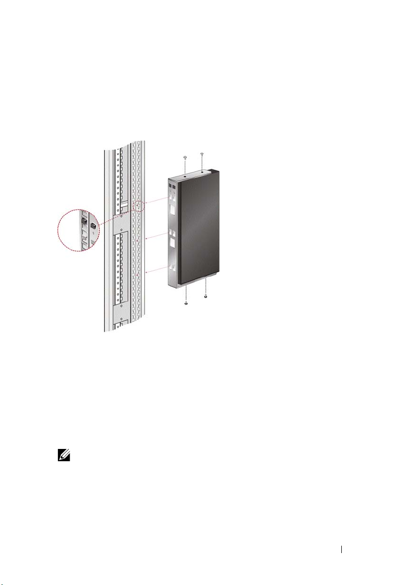
3 Mount the switch assembly to the rack by inserting the three mounting
hooks on one side of the bracket into square holes in the vertical rack.
4 Press down until the blue push button pops out and clicks.
Figure 2-1. OU Mounting Bracket Installation
To install the 2161DS-2/4161DS Remote Console Switch 1U four point
switch mounting bracket:
1 Remove the screws on each side of the 1U four-point switch and set
them aside to attach to the front 1U bracket pieces later.
2 Line up the vent holes in the “long side” of the kit’s front brackets with
the vent holes in the switch.
NOTE: The switch vent holes must not be covered by the bracket, which will occur
if installed on the wrong side of the switch.
3 Line up the screw holes in the bracket with the screw holes in the switch.
4 With a Phillips screwdriver, fasten the front mounting brackets to the
switch using two screws on each side.
Installation 12
Page 30
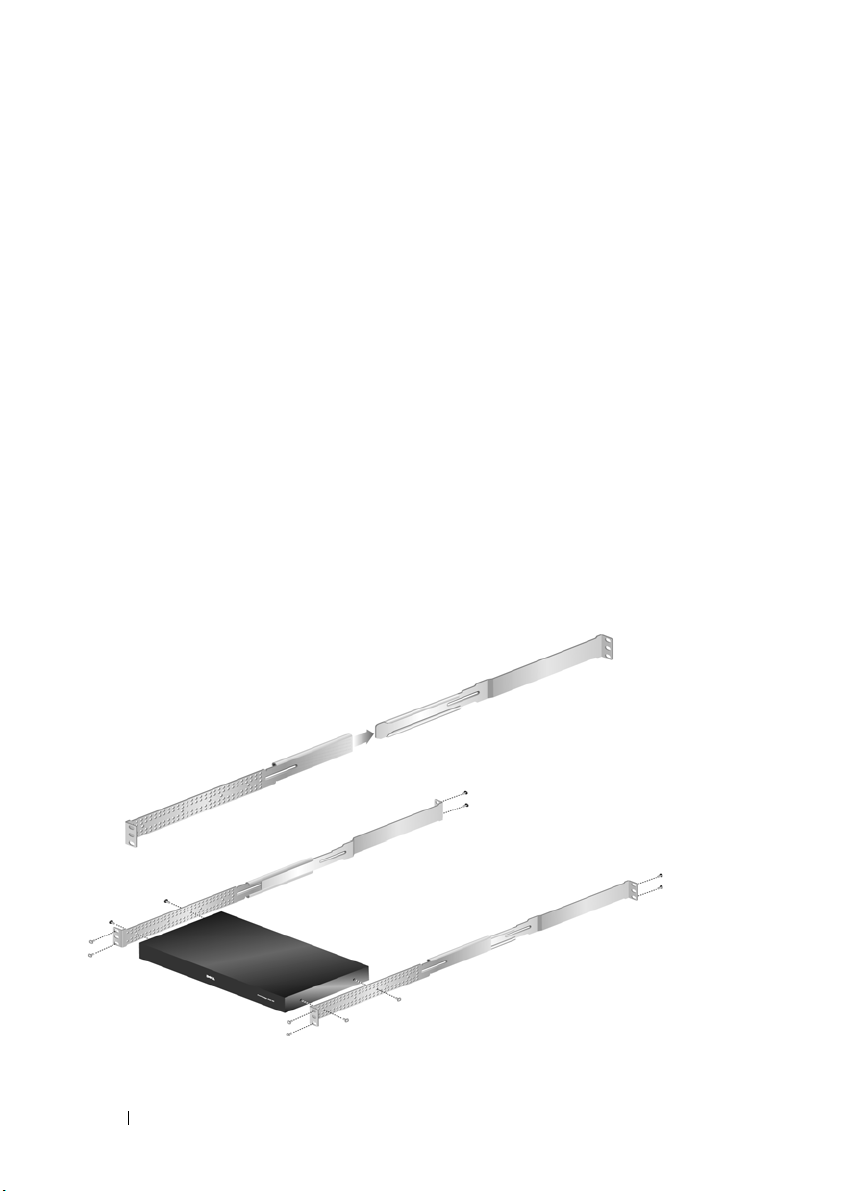
5 Attach four cage nuts or clip nuts to the rack mounting flange of the
rack cabinet’s front so that the nut is positioned on the inside of the
rack.
6 Mount the switch assembly to the rack cabinet by matching the holes in
the “short side” of each bracket to an appropriate set of matching holes
on your rack cabinet. Next, insert the combination hex head screws
through the slots in the bracket, then the holes in the mounting rail, and
then into the cage nuts or clip nuts.
7 Attach four cage nuts or clip nuts to the rack mounting flange of the
rack cabinet back so that the nut is positioned on the inside of the rack.
8 Slide the rear brackets into the channel of the front brackets adjusting
them to fit the rack depth.
9 Mount the rear bracket to the rack cabinet by matching the holes in the
“short side” of each bracket to an appropriate set of matching holes on
your rack cabinet, ensuring the switch is level within the rack.
10 Insert the combination hex head screws through the slots in the bracket
and the holes in the mounting rail, then into the cage nuts or clip nuts.
Figure 2-2. 2161DS-2/4161DS Remote Console Switch 1U Mounting Bracket Installation
To install the 2321DS Remote Console Switch mounting bracket:
13 Installation
Page 31

1
Remove the three truss head screws from the right side of the switch
chassis, and position and attach the right mounting bracket to the right
side of the switch chassis with three of the flat head screws provided.
NOTE: The switch vent holes must not be covered by the bracket, which will occur
if installed on the wrong side of the switch.
2
Repeat the procedure for the left side of the switch chassis.
3
Install a push nut to one end of the cable support rod. Position the
extensions with their slotted mounting flanges facing in opposing
directions.
4
Select a position hole on the lower side of the slide extensions. Slide the
support rod through the selected hole and the hole on the opposite
extension.
5
Install the remaining push nut on the other end of the cable support rod.
6
Slide the extension assembly into the switch chassis/bracket assembly as
shown in the illustration. Be sure to orient the extension assembly so that
the cable support rod is in the lower row of extension holes.
7
Place the complete switch chassis/bracket assembly into a level rack
position and install the appropriate hardware into each of the four bracket
corners (hardware not provided).
Installation 14
Page 32

Figure 2-3. 2321DS Remote Console Switch Mounting Bracket Installation
Installing the Remote Console Switch Unit
The diagram below illustrates one possible configuration for your Remote
Console Switch appliance. Follow the detailed set of procedures following
Figure 2-4 to successfully install your Remote Console Switch unit.
15 Installation
Page 33

Figure 2-4. Basic Remote Console Switch Configuration
4
3
8
2
6
9
7
5
1
Table 2-1. Basic Remote Console Switch Configuration Descriptions
Number Description Number Description
1
2
3
4
5
Power Cord
Analog User
Digital User
Network
USB Devices
6
7
8
9
Servers 2-16
ARI Port
SIP or Avocent IQ Module
Server 1
Installation 16
Page 34

CAUTION: To reduce the risk of electric shock or damage to your equipment, do
not disable the power cord grounding plug. The grounding plug is an important
safety feature. Plug the power cord into a grounded (earthed) outlet that is easily
accessible at all times. Disconnect the power from the unit by unplugging the
power cord from either the electrical outlet or the unit.
NOTE: If the building has 3-phase AV power, ensure that the computer and monitor
are on the same phase to avoid potential phase-related video and/or keyboard
problems.
NOTE: The maximum supported cable length from switch to device is 30 meters.
To install the Remote Console Switch hardware:
NOTE: The default username is “Admin.” There is no default password.
1 Connect a terminal or PC running the terminal emulation software to
the configuration port on the back panel of the Remote Console Switch
using the supplied serial cable. The terminal should be set to 9600 baud,
8 bits, 1 stop bit, no parity, and no flow control.
2 Plug the supplied power cord into the back of the Remote Console
Switch unit and then into an appropriate power source.
3 When the power is switched on, the Power indicator on the rear of the
unit will blink for 30 seconds while performing a self-test. Press the
<Enter> key to access the main menu.
17 Installation
Page 35

Figure 2-5. Main Menu
To configure the Remote Console Switch hardware:
1 You will see the Main menu with eleven options. Select option 1,
Network Configuration.
Installation 18
Page 36

Figure 2-6. Network Configuration Menu
2 Select option 1 to set your network speed. Once you enter your
selection, you will be returned to the Network Configuration menu.
3 Select option 2 to open the IP Configuration menu.
4
Type the appropriate number to select one of the following types of IP
addresses:
IPv6 Dynamic
1: None, 2: IPv4 Static, 3: IPv4 Dynamic, 4: IPv6 Static
.
Dell recommends using a static IP address for ease of configuration.
, or 5:
5 Select options 3-5 from the Terminal Applications menu, in turn, to
finish configuring your Remote Console Switch for IP address, Netmask,
and Default Gateway.
6 Once this is completed, type Ø to return to the main menu.
NOTE: Network configuration can also be performed. See "Controlling Your System
at the Analog Ports" on page 36.
To configure the HTTP and HTTPS ports:
1 You will see the Main menu with eleven options. Select option 10, Set
Web Interface Ports to open the Web Interface Port Configuration
Menu.
19 Installation
Page 37

Figure 2-7. Web Interface Port Configuration Menu
2
Select option 1 to set the port numbers. Type the port numbers you wish
to use for the HTTP port and the HTTPS port.
Figure 2-8. Web Interface Port Configuration Menu - Set Ports Option
3
If the values are correct for your network, type <Y> and press the
<Enter> key.
NOTE: You will need to reboot the Remote Console Switch to use these port
numbers.
Installation 20
Page 38

NOTE: If you change the port numbers in the Remote Console Switch, you will also
need to change them in the Remote Console Switch Software (see "Adding a
Remote Console Switch or Avocent Remote Console Switch" on page 68 or
"Changing Switch Network Properties" on page 81) or the web interface (see
"Launching the On-board Web Interface" on page 32).
To input and install a web certificate:
1 You wi ll se e t he Main menu with eleven options. Select option 11, Input
Web Server Certificate, to open the Input Web Server Certificate
Menu.
Figure 2-9. Web Server Certificate Input Menu
2
Select option 1,
21 Installation
User Input
.
Page 39

Figure 2-10. User Input Menu
3
Either press the <Enter> key to accept the default options, or enter the
appropriate text in the following fields:
a
Public Key Length
b
Common Name
: the number of bits you want the certificate to be.
: your name. (Since this is your root certificate, use an
appropriate name such as, "Company_Name Certificate Authority.")
c
Organizational Unit
(optional): organization unit name (marketing,
for example)..
d
Organization Name
: the exact legal unabbreviated name of your
organization.
e
Locality Name
f
State or Province Name
: the city where your organization is located.
: the unabbreviated state or province where
your organization is located.
g
Country Name
h
Email Address
i
Val i di t y Ter m
4
Press the <Enter> key. Wait for the Web Server to restart before
: the two-letter ISO abbreviation for your country.
: the email address for the CA to contact.
: number of days the certificate is valid.
continuing.
To import and install a web certificate:
Installation 22
Page 40

1 You wi ll se e t he Main menu with eleven options. Select option 11, Input
Web Server Certificate, to open the Input Web Server Certificate
Menu.
2
Select option 2,
(*.pem). Wait for the Web Server to restart before continuing.
To export a web certificate:
1 You wi ll se e t he Main menu with eleven options. Select option 11, Input
Web Server Certificate, to open the Input Web Server Certificate
Menu.
2
Select option 3,
console. The format must be similar to the following text:
"-----BEGIN CERTIFICATE----MIIDJzCCApCgAwIBAgIBADANBgkqhkiG9w0BAQQFADBxMQswC
QYDVQQGEwJVUzEQ
............. Text removed from example
........................
3omoTQuBURERxg3vrwEzLqCUanQmw5BQJAVC6LT/DP7DNz/xi
pZoI+ZyaTgQEdR0
R0x0yYSaYETpMY53NMAVlCxETVkvkI2F/f+1sn+9Ik7GWBuPp
LbTmYfMoQ==
-----END CERTIFICATE-----
-----BEGIN RSA PRIVATE KEY----MIICXAIBAAKBgQDI6KTaqoPfZhK7Wdd+Dzx03IVQlBqp+Vslt
n34YMDdpJ8mfqND
............. Text removed from example
........................
b6KA7VfijVhIt3lKcYsCQEhOjqh07hI5OLmSHt3l1krGZTX+A
Cy1dlceZRkJDkyA
HqTleb5fx/i1Hu5ex99qQP9FSOP5fVsmVSRDkk2ites=
-----END RSA PRIVATE KEY-----"
Import Cert
Export Cert,
. Then download a company certificate file
to output the current certificate to the serial
To return to the factory defaults:
1 You wi ll se e t he Main menu with eleven options. Select option 11, Input
Web Server Certificate, to open the Input Web Server Certificate
Menu.
2
Select option 4,
the factory defaults.
23 Installation
Restore Defaults,
to replace the current certificate with
Page 41

Video Optimization
To ensure optimal video quality, configure the Remote Console Switch with
the same settings as the network switch. For example, if the Remote Console
Switch is set to Auto-Negotiate, then the network switch must be set to Auto-
Negotiate in both speed and duplex. For example, if the Remote Console
Switch is set to 100MB - full duplex, then the network switch must be set to
100MB - full duplex.
Once you have made these changes, you may need to refresh/flush the
Address Resolution Protocol (ARP) tables in the network before you establish
a new connection with the Remote Console Switch, especially if the Remote
Console Switch has been in use within the hour preceding these changes.
To refresh the ARP table, do one of the following:
Wait approximately 10 minutes for the ARP tables to rebuild automatically.
-or-
Clear the ARP table entry in a video session viewer workstation and ping the
appliance at its IP address. This can be done from a DOS window.
a Ty p e ARP -d 1.2.3.4
(where 1.2.3.4 is the IP address of the Remote Console Switch).
b Ty p e PING 1.2.3.4
If the PING is successful, the Remote Console Switch is ready for operation.
Mouse Acceleration
NOTE: Dell highly recommends that all Microsoft® Windows® systems attached to
the Remote Console Switch use the default Windows
®
PS/2 or USB mouse driver.
If you are experiencing slow mouse response during a remote video session,
deactivate mouse acceleration in the operating system of the target device
and set mouse speed to 50%.
Connecting a SIP
To connect a SIP to each server:
1 Locate the SIPs for your Remote Console Switch unit.
2 If you are using a PS/2 SIP connection, attach the SIP’s color-coded ends
to the appropriate keyboard, monitor, and mouse ports on the first server
you will be connecting to this Remote Console Switch. If you are using a
Installation 24
Page 42

USB connection, attach the SIP’s plug to the USB port on the first
server you will be connecting to this Remote Console Switch unit
(Figure 2-11).
3 To the RJ-45 connector on the SIP, attach one end of the CAT 5 cabling
that will run from your SIP to the Remote Console Switch unit
(Figure 2-11).
4 Connect the other end of the CAT 5 cable to the desired ARI port on
the back of your Remote Console Switch unit.
5 Repeat steps 2-4 for all servers you wish to attach.
NOTE: Power down the Remote Console Switch unit before servicing. Always
disconnect the power cord from the wall outlet.
NOTE: In addition to Dell SIPs, the Remote Console Switch may also be connected
to devices using Avocent IQ modules, including Sun and Serial IQ modules.
25 Installation
Page 43

Figure 2-11. Connecting a SIP
1
2
3
Table 2-2. Connecting a SIP Descriptions
Number Description
1
2
3
Adding a Cascade Switch
CAT 5
USB Connection
PS/2 Connection
To add a cascade switch (optional):
NOTE: The Remote Console Switch does not support the EL80-DT.
1 Mount the switch into your rack. Locate a CAT 5 cable to connect your
Remote Console Switch unit to the cascade switch (Figure 2-13).
Installation 26
Page 44

2 Attach one end of the CAT 5 cabling to the ARI port on the Console
Switch.
3 Connect the other end of the CAT 5 cable to the ACI port on the back
of your cascade switch.
4 Connect the devices to your cascaded switch according to the switch
manufacturer's recommendations.
5 Repeat steps 1-4 for all the cascade switches you wish to attach to your
Remote Console Switch system.
27 Installation
Page 45

Figure 2-12. Remote Console Switch With a Cat 5 Analog Switch
1
2
3
Table 2-3. Remote Console Switch With
Number Description
1
2
3
NOTE: The Remote Console Switch supports only 1 switch per ARI port. You cannot
cascade another switch under this first switch.
Local User
CAT 5
ACI Port
a Cat 5 Analog Switch Descriptions
Installation 28
Page 46

NOTE: When cascading with a Remote Console Switch, an 8-port or 16-port analog
console switch is not supported as the primary unit in a cascaded configuration.
The Remote Console Switch must be the primary unit.
Cascading with Legacy Switches
To add a legacy switch (optional):
1 Mount the switch into your rack. Locate a CAT 5 cable to connect your
Remote Console Switch unit to the legacy switch (Figure 2-13).
2 Attach one end of the CAT 5 cabling to the ARI port on the Console
Switch.
3 Connect the other end of the CAT 5 cable to a Dell SIP or Avocent IQ
module.
4 Connect the SIP or IQ module to your legacy switch according to the
switch manufacturer's recommendations.
5 Repeat steps 1-4 for all the legacy switches you wish to attach to your
Remote Console Switch system.
NOTE: The Remote Console Switch supports only 1 switch per ARI port. You cannot
cascade another switch under this first switch.
NOTE: When cascading with a Remote Console Switch, an 8-port or 16-port analog
console switch is not supported as the primary unit. The Remote Console Switch
must be the primary unit.
29 Installation
Page 47

Figure 2-13. Remote Console Switch Cascading Configuration With Legacy Console
Switches
Adding a PEM (Optional)
A Port Expansion Module (PEM) allows you to expand each ARI port to
accommodate up to eight devices instead of one.
NOTE: The PEM operates passively. Therefore, once a user accesses a device
attached to a PEM, any subsequent users attempting to access any of the devices
attached to that PEM will be blocked.
To add a PEM (optional):
1 Mount the PEM into your rack. Using up to nine CAT 5 cables, one
connects your Remote Console Switch unit to the PEM, and the other
eight connect the PEM to the SIP attached to each device.
Installation 30
Page 48

2 Attach one end of the CAT 5 cabling that will run between your PEM
Analog User
1
2
3
4
5
and the Remote Console Switch unit to the RJ-45 connector slightly
separated from the other connectors on the PEM. Connect the
remaining end of the CAT 5 cable to the desired ARI port on the back of
your Remote Console Switch unit.
3 To one of the eight RJ-45 connectors grouped on the back of the PEM,
attach the CAT 5 cabling that will run between your PEM and each
device’s SIP.
4 Connect the other end of the CAT 5 cable to the first of the SIPs.
5 Repeat steps 3-4 for all devices you wish to attach.
Figure 2-14. Remote Console Switch Configuration With a PEM
Table 2-4. Remote Console Switch Configuration With a PEM Descriptions
Number Description
1
31 Installation
ARI Port
Page 49

Table 2-4. Remote Console Switch Configuration With a PEM Descriptions
Number Description
2
3
4
5
CAT 5e
PEM
SIP or Avocent IQ Module
Server
Connecting to the Network
To connect the network and power up your Remote Console Switch:
1 Connect your network cable to the LAN port on the rear of the Remote
Console Switch to your network.
NOTE: If you are using a 2321DS Remote Console Switch, you will have two
redundant LAN ports. If the first LAN port fails, the second one will take over.
2 Power up all attached systems in any order.
3 Attach your monitor and keyboard and mouse cable connectors to the
appropriate ports on the back of your Remote Console Switch unit.
On-board Web Interface Installation and Setup
Once you have installed a new Remote Console Switch, you can use the onboard web interface to configure unit parameters and launch video sessions.
Supported Browsers
The on-board web interface supports the following browsers:
• Microsoft Internet Explorer® version 6.x SP1 or later
• Firefox version 2.0 or later
Launching the On-board Web Interface
To launch the on-board web interface:
1
Open a web browser and type the IP address of the Remote Console
Switch. You can set the IP address of the switch using OSCAR or the serial
port; see "Controlling Your System at the Analog Ports" on page 36 for
more information.
Installation 32
Page 50

NOTE: If you changed the default HTTP/HTTPS ports in the serial console and are
using an IPv4 address, use this IP address format: "https://<ipaddress>:<port#>",
where "port#" is the number you changed the port number to in the serial console. If
you are using an IPv6 address, use this format: "https://[<ipaddress>]:<port#>",
where "port#" is the number you changed the port number to in the serial console. If
you are using an IPv6 address, you must enclose the address in square brackets.
2
The login window opens. Type your username and password and click OK.
3
The on-board web interface opens and displays the
NOTE: The Remote Console Switch will attempt to detect if Java is already installed
on your PC. If it is not, in order to use the on-board web interface, you will need to
install it. You may also need to associate the JNLP file with Java WebStart.
NOTE: Using the on-board web interface requires using Java Runtime Environment
(JRE) version 1.6.0_2 or higher.
NOTE: Once you have logged in to the on-board web interface, you will not have to
log in again when launching new sessions unless you have logged out or your
session has exceed the inactivity timeout specified by the administrator.
Connections
tab.
Remote Console Switch Software Installation and Setup
Before installing your Dell Remote Console Switch Software, refer to the
following lists to ensure that you have all the items that shipped with your
software as well as all other items necessary for proper installation.
Supplied with the Remote Console Switch Software
Your Dell Remote Console Switch package contains the following items:
• Dell Remote Console Switch System User’s Guide and Remote
Console Switch Software CD
• Download Instructions
• Safety Booklet
Supported Operating Systems
The Remote Console Switch Software is supported on the following
operating systems:
33 Installation
Page 51

•Windows Server® 2003 Service Pack 1 (Web, Standard, and
Enterprise)
• Windows XP (Professional) Service Pack 2
•Windows Vista
®
Business
• Windows 2008 Server
•Red Hat
•SUSE
®
Enterprise Linux® versions 3, 4 or 5 (WS, ES, and AS)
®
Linux Enterprise Server version 9 or 10
System Hardware Configuration Requirements
The following list contains the hardware configuration requirements for
running the Remote Console Switch Software on the supported operating
systems. Configurations with less than the recommended requirements are
not supported.
• 500 MHz Intel® Pentium® III
• 256 MB of RAM
• 10 or 100BaseT NIC (100 recommended)
• XGA Video with graphics accelerator
• Desktop size must be a minimum of 800 x 600
• Color palette must be a minimum of 65,536 (16-bit) colors
Supported Browsers
The Remote Console Switch Software supports the following browsers:
• Microsoft Internet Explorer version 6.x SPI or later
• Firefox version 2.0 or later
Installing the Remote Console Switch Software
The Remote Console Switch Software can be installed on Windows and
Linux platforms. Follow these instructions to install Remote Console Switch
Software on the desired platform.
To install on Windows:
Installation 34
Page 52

1
Insert the Remote Console Switch Software CD-ROM into your CDROM drive. If AutoPlay is supported and enabled, the setup program will
start automatically.
-orIf your system does not support AutoPlay, set the default drive to your CDROM drive letter and execute the following command to start the install
program (replace “drive” with your CD-ROM drive letter):
drive:\WIN32\SETUP.EXE.
2
Follow the on-screen instructions.
To install on Linux:
1
Insert the Remote Console Switch Software CD-ROM into your CDROM drive.
2
If AutoMount is supported and enabled, proceed to step 3.
-orIf your system does not support AutoMount:
Mount the CD-ROM volume by executing the following command:
mount -t iso9660 -ro mode=0555 <device> <mount point>
Replace “device” with the name of the CD-ROM on your machine and
mount point with the name of the desired mount point. For example, to
mount a CD-ROM which is the second IDE unit on /mnt, execute the
command:
mount -t iso9660 -ro mode=0555 /dev/hdb /mnt
3
At the command-line, execute the following command to change the
working directory to the mount point:
cd /mnt
4
Execute the following command to start the install program:
sh ./linux/setup.bin
5 Follow the on-screen instructions.
35 Installation
Page 53

3
Controlling Your System at the Analog Ports
The Remote Console Switch features user-side keyboard and mouse ports
that allow you to connect a USB or PS/2 keyboard and mouse for direct analog
access. The Remote Console Switch uses the powerful OSCAR interface,
which uses intuitive menus to configure your system and select computers.
Viewing and Selecting Ports and Devices
Use the OSCAR Main dialog box to view, configure, and control devices in
the Remote Console Switch system. View your devices by name, port, or by
the unique Electronic ID number (EID) embedded in each SIP module.
The Port column indicates the ARI port to which a device is connected. If you
cascade a switch from the main Remote Console Switch, creating another
tier, the port numbering displays the ARI port first, then the switch port to
which the device is connected. For example, in Figure 3-1, devices 06-01, 0602, 06-03, and 06-04 are connected to switches. The port numbering displays
the ARI port first, then the switch port to which the device is connected. If
you cascade a switch from a Port Expansion Module (PEM), you will also see
multiple devices that show up on a single port.
To access the Main dialog box:
Press <Print Screen> to launch the OSCAR interface. The Main dialog box
displays.
Controlling Your System at the Analog Ports 36
Page 54

Figure 3-1. Example of a Main Dialog Box
NOTE: You can also press the <Control>, <Alt>, or <Shift> keys twice within one
second to launch the
place you see <Print Screen> throughout this chapter.
OSCAR
interface. You can use this key sequence in any
Viewing the Status of Your Switch
The status of the devices in your system is indicated in the right columns of
the Main dialog box. Table 3-1 describes the status symbols.
Table 3-1. OSCAR Interface Status Symbols
Symbol Description
SIP is online.
SIP is offline or is not operating properly.
Connected switch is online.
Connected switch is offline or is not operating properly.
SIP is unavailable.
(green letter) Indicates which user channel is currently
connected to a SIP.
37 Controlling Your System at the Analog Ports
Page 55

Table 3-1. OSCAR Interface Status Symbols
Symbol Description
(black letter) Indicates a blocked path. For instance, in
Figure 3-1, user C is viewing Forester, but is blocking access to
Acton, Barrett, and Edie, which are connected to the same
ARI port.
(blue letter) Indicates a virtual media connection.
Selecting Devices
Use the Main dialog box to select devices. When you select a device, the
appliance reconfigures the keyboard and mouse to the proper settings for that
device.
To select devices:
Double-click the device name, EID, or port number.
-orIf the display order of your device list is by port (Port
type the port number and press <Enter>.
-orIf the display order of your device list is by name or EID number (Name
EID
button is depressed), type the first few characters of the name of the
device or the EID number to establish it as unique and press <Enter>.
button is depressed),
or
NOTE: You can connect to the selected device by pressing <Enter>.
To select the previous device:
Press <Print Screen>
and then <Backspace>. This key combination toggles
between the previous and current connections.
To disconnect the user from a device:
Press <Print Screen> and then <Alt+0> or click Disconnect in the OSCAR
interface. This leaves the user in a free state, with no device selected. The
status flag on your desktop displays Free.
Soft Switching
Soft switching is the ability to switch devices using a hot key sequence. You
can soft switch to a device by pressing <Print Screen> and then typing the
Controlling Your System at the Analog Ports 38
Page 56

first few characters of its name or number. If you have set a Screen Delay
Time and you press the key sequences before that time has elapsed, the
OSCAR interface will not display.
To set a screen delay time:
1
Press <Print Screen> to launch the OSCAR interface. The
box appears.
2
Click
Setup - Menu. The
3
For
Screen Delay Time
before the
4
Click OK.
To soft switch to a device:
1
To select a device, press <Print Screen>. If the display order of your device
list is by port (
<Enter>.
-orIf the display order of your device list is by name or EID number (
EID button is depressed), type the first few characters of the name of the
device or the EID number to establish it as unique and press <Enter>.
2
To switch back to the previous device, press <Print Screen> then
<Backspace>.
Main
dialog box is displayed after you press <Print Screen>.
Port button is depressed), type the port number and press
Menu
dialog box displays.
, type the number of seconds of delay desired
Main
dialog
Name or
Navigating the OSCAR Interface
Table 3-2 describes how to navigate the OSCAR interface using the keyboard
and mouse.
NOTE: You can also press the <Control>, <Alt>, or <Shift> keys twice within one
second to launch the OSCAR interface. You can use this key sequence in any
place you see <Print Screen> throughout this chapter.
39 Controlling Your System at the Analog Ports
Page 57

Table 3-2. OSCAR Interface Navigation Basics
This Keystroke Does This
<Print Screen>,
Ctrl-Ctrl, ShiftShift and/or AltAlt
<Print Screen> Press <Print Screen> twice to send the <Print Screen>
F1 Opens the Help screen for the current dialog box.
Escape Closes the current dialog box without saving changes and returns
OSCAR activation sequence. By default, <Print Screen> and
Ctrl-Ctrl are set as the OSCAR activation options. Shift-Shift
and Alt-Alt must be set within OSCAR before use.
keystroke to the currently selected device.
to the previous one. In the Main dialog box, it closes the
OSCAR interface and returns to the status flag. In a message
box, it closes the pop-up box and returns to the current dialog
box.
Alt+Hotkey Opens dialog boxes, selects or checks options, and executes
actions when used with underlined letters.
Alt+X Closes the current dialog box and returns to the previous one.
Alt+O Selects the OK button, then returns to the previous dialog box.
Click, Enter In a text box, selects the text for editing and enables the left-and
right-arrow keys to move the cursor. Press <Enter> to select the
entire field contents.
Enter Completes a switch in the Main dialog box and exits the
OSCAR interface.
<Print Screen>,
Backspace
<Print Screen>,
Alt+0
<Print Screen>,
Pau se
Up/Down Arrows Moves the cursor from line to line in lists.
Right/Left Arrows Moves the cursor within the column when editing a text box.
Toggles back to previous selection.
Immediately disengages a user from a server; no server is
selected. Status flag displays Free. (This only applies to the 0
on the keyboard and not the keypad.)
Immediately turns on screen saver mode and prevents access to
that specific console, if it is password protected.
Controlling Your System at the Analog Ports 40
Page 58

Table 3-2. OSCAR Interface Navigation Basics (continued)
This Keystroke Does This
Pag e Up/Page
Down
Home/End Moves the cursor to the top or bottom of a list.
Delete Deletes current selection in the scan list or characters in a text
Numbers Type from the keyboard or keypad.
Pages up and down through Name and Port lists and Help pages.
box.
Configuring OSCAR Interface Menus
You can configure your Remote Console Switch from the Setup menu within
the OSCAR interface. Select the Names button when initially setting up your
appliance to identify devices by unique names. Select the other setup features
to manage routine tasks for your devices from the OSCAR interface menu.
See Table 3-3.
Table 3-3. Setup Features to Manage Routine Tasks for Your devices
Feature Purpose
Menu Change the device listing between numerically by port or EID
number and alphabetically by name. Change the Screen Delay
Time before the
<Print Screen>.
Security Set passwords to restrict device access. Enable the screen saver.
Flag Change display, timing, color, or location of the status flag.
Language Choose the language display.
Devices Identify the appropriate number of ports on an attached
cascaded switch.
Names Identify devices by unique names.
Keyboard Choose your keyboard country code.
Broadcast Set up to simultaneously control multiple devices through
keyboard and
mouse actions.
OSCAR interface displays after pressing
41 Controlling Your System at the Analog Ports
Page 59

Table 3-3. Setup Features to Manage Routine Tasks for Your devices (continued)
Feature Purpose
Scan Set up a custom scan pattern for up to 100 devices.
Switch Choose the switch mode and the share mode time-out.
Network Choose your network speed, transmission mode, and
configuration.
VMedia Set the behavior of the appliance during a virtual media session.
PDUs (For 2321DS
Remote Console
Switch only.)
View which PDUs are connected to your system.
To access the Setup menu:
1
Press <Print Screen> to launch the OSCAR interface. The
Main
dialog
box appears.
2
Click
Setup
. The
Setup
dialog box displays.
Figure 3-2. Setup Dialog Box
Changing the Display Behavior
Use the Menu dialog box to change the display order of devices, set a Screen
Delay Time for the OSCAR interface, and change the OSCAR launch
sequence. The display order setting alters how devices display in several
screens including the Main, Devices, and Broadcast dialog boxes.
Controlling Your System at the Analog Ports 42
Page 60

To access the Menu dialog box:
1
Click
Setup - Menu
in the
Main
dialog box. The
Menu
dialog box
displays.
Figure 3-3. Menu Dialog Box
2
<Print Screen>,
Ctrl-Ctrl, Alt-Alt,
and
Shift-Shift
are selectable to
launch the OSCAR interface. One or all of the above keyboard
combinations can be selected at a time. If only one keyboard combination
is selected, it cannot be de-selected until a second one is chosen.
To choose the default display order of devices:
1
Select
Name
to display devices alphabetically by name.
or
Select
EID
to display devices numerically by EID number.
or
Select
Port to display devices numerically by port number.
2
Click OK.
To set a Screen Delay Time for the OSCAR interface:
1
Type in the number of seconds (0 to 9) to delay the OSCAR interface display
after you press <Print Screen>. Enter
0
to launch the OSCAR interface
without delay.
2
Click OK.
43 Controlling Your System at the Analog Ports
Page 61

By setting a Screen Delay Time, you can complete a soft switch without
displaying the OSCAR interface. To perform a soft switch, see "Soft
Switching" on page 38 in this chapter.
Setting Console Security
The OSCAR interface enables you to set security on your analog port console.
You can establish a screen saver mode that engages after your console remains
unused for a specified Inactivity Time. After it is engaged, your console
remains locked until you press any key or move the mouse. You must type in
your password to continue.
Use the Security dialog box to lock your console with password protection, set
or change your password, and enable the screen saver.
To access the Security dialog box:
1
Press <Print Screen> to launch the OSCAR interface. The
box appears.
2
Click
Setup - Security
Figure 3-4. Security Dialog Box
. The
Security
dialog box displays.
Main
dialog
NOTE: If the New and Repeat fields contain six asterisks, a password has already
been established.
To set or change the password:
NOTE: If you lose or forget your password, please contact Dell Technical Support.
See Appendix G: Technical Support for contact information.
Controlling Your System at the Analog Ports 44
Page 62

1
Click in the
2
Type the new password in the
New
text box.
New
text box. Passwords must contain both
alpha and numeric characters, are case sensitive, and may be up to 12
characters long. Legal characters are: A to Z, a to z, 0 to 9, and hyphen.
3
In the
Repeat
box, type the password again.
4
Click OK to change only your password, and then close the dialog box.
To password protect your console:
1
Set your password as described in the previous procedure.
2
Select
Enable Screen Saver
3
Type the number of minutes for
.
Inactivity Time
(from 1 to 99) to delay
activation of password protection and the screen saver feature.
4
For Mode, sel ect
otherwise select
CAUTION: Monitor damage can result from the use of Energy mode with monitors
not compliant with Energy Star®.
5
(Optional) Click
seconds then returns you to the
6
Click OK.
Energy
Screen
if your monitor is E
.
NERGY STAR
Te st to activate the screen saver test, which lasts 10
Security
dialog box.
®
compliant;
To log in to your console:
1
Press any key or move the mouse.
2
The
Password
3
The
Main
dialog box displays. Type your password, then click OK.
dialog box displays if the password was entered properly.
To remove password protection from your console:
1
From the
2
In the
Main
Security
dialog box, click
Setup - Security
dialog box, click in the
.
New
box. Leave the box blank. Press
<Enter>.
3
Click in the
4
Click OK to eliminate your password.
Repeat
box. Leave the box blank.
To enable the screen saver mode with no password protection:
45 Controlling Your System at the Analog Ports
Page 63

1
If your console does not require a password to gain access to the
Security
dialog box, proceed to step 2.
or
If your console is password protected, see the previous procedure, then go
to step 2.
2
Select
Enable Screen Saver
3
Type the number of minutes for Inactivity Time (from 1 to 99) to delay
.
activation of the
screen saver.
4
Choose
select
CAUTION: Monitor damage can result from the use of Energy mode with monitors
not compliant with Energy Star®.
5
(Optional) Click
seconds then returns you to the
6
Click OK.
NOTE: Activation of the screen saver mode disconnects the user from a device; no
device is selected. The status flag displays the status “Free.”
Energy
Screen
if your monitor is E
.
Te st
to activate the screen saver test, which lasts 10
NERGY STAR
Security
dialog box.
®
compliant; otherwise
To exit the screen saver mode:
Press any key or move your mouse. The Main dialog box displays and any
previous device connection is restored after the password is validated by the
appliance.
To turn off the screen saver:
1
In the
2
Click OK.
Security
dialog box, clear
Enable Screen Saver
.
To immediately turn on the screen saver:
Press <Print Screen>, then press <Pause>.
Controlling the Status Flag
The status flag displays on your desktop and shows the name or EID number
of the selected device or the status of the selected port. Use the Flag dialog
box to configure the status flag to display by device name or EID number, or
to change the status flag color, opacity, display time, and location on the
desktop.
Controlling Your System at the Analog Ports 46
Page 64

To access the Flag dialog box:
1
Press <Print Screen> to launch the OSCAR interface. The
box appears.
2
Click
Setup - Flag
Figure 3-5. Flag Dialog Box
. The
Flag
dialog box displays.
To determine how the status flag is displayed:
1
Select
Name or
2
Select
Displayed to show the status flag.
3
(Optional) Select
EID to determine what information will be displayed.
Timed
to display the status flag for only five seconds
after switching.
4
Select a status flag color in
5
In
Display Mode
, select
Display Color
.
Opaque for a solid color status flag or select
Transparent to see the desktop through the status flag.
6
To position the status flag on the desktop:
a
Click
Set Position
b
Click on the title bar and drag to the desired location.
to gain access to the
Set Position Flag
-orUse the left and right arrows to nudge the status flag to the desired
location and press <Enter>.
c
Right-click to return to the
Flag
dialog box.
Main
screen.
dialog
47 Controlling Your System at the Analog Ports
Page 65

NOTE: Changes made to the status flag position are not saved until you click OK in
the Flag dialog box.
7
Click OK to save settings.
or
Click
X
to exit without saving changes.
Setting the Interface Language
You can change the OSCAR interface to any one of 4 supported languages by
selecting your chosen language in the Language dialog box.
To change the OSCAR interface language:
1
Press <Print Screen> to launch the OSCAR interface. The
box appears.
2
Click
Setup - Language
Figure 3-6. Language Dialog Box
. The
Language
dialog box displays.
Main
dialog
3
Click to select the language you want the OSCAR interface to appear in.
4
Click
OK
to accept the change you have made and return to the
dialog box. The
Setup
dialog box displays in the language you have
Setup
selected.
Assigning Device Types
The Remote Console Switch automatically discovers cascaded KVM
switches, but you need to specify the number of ports on the cascaded switch
through the Devices dialog box. An Sw-8 or Sw-24 in the Ty p e category for
Controlling Your System at the Analog Ports 48
Page 66

the cascaded switch is visible on screen. When you select from the list, the
Modify button is enabled, allowing you to assign it the appropriate number of
ports.
NOTE: The Modify button is available only if a configurable switch is selected.
To access the Server dialog box:
1
Press <Print Screen> to launch the OSCAR interface. The
Main
dialog
box appears.
2
Click
Setup - Devices. The
Figure 3-7. Devices Dialog Box
Devices
dialog box displays.
When the Remote Console Switch discovers a cascaded switch, the port
numbering changes to accommodate each device under that switch. For
example, if the switch is connected to ARI port 6, the switch port is listed as
06 and each device under it is numbered sequentially 06-01, 06-02 and so on.
NOTE: Changes made in the Device Modify dialog box are not saved until you click
OK in the Devices dialog box.
To assign a device type:
1
In the
2
Click
Devices
Modify
dialog box, select the desired port number.
. The
Device Modify
dialog box displays.
49 Controlling Your System at the Analog Ports
Page 67

Figure 3-8. Device Modify Dialog Box
3
Choose or enter the number of ports supported by your cascaded switch
and click
4
Repeat steps 1 to 3 for each port requiring a device type to be assigned.
5
Click OK in the
OK
.
Devices
dialog box to save settings.
Assigning Device Names
Use the Names dialog box to identify individual devices by name rather than
by port number. The Names list is always sorted by port order. Names are stored
in the SIP module, so even if you move the SIP/server to another ARI port, the
name and configuration is recognized by the switch.
NOTE: If a device is turned off, the respective SIP module does not appear in the
Names list.
To access the Names dialog box:
1
Press <Print Screen> to launch the OSCAR interface. The
Main
box appears.
2
Click
Setup - Names. The
NOTE: If the server list changes, the mouse cursor turns into an hourglass as the
list is automatically updated. No mouse or keyboard input is accepted until the list
update is complete.
NOTE: If a SIP module is not assigned a name, the EID is used as the default name.
Names
dialog box displays.
To assign names to devices:
Controlling Your System at the Analog Ports 50
dialog
Page 68

1
In the
Names
dialog box, select a device name or port number and click
Modify
2
Type a name in the
characters long. Legal characters include: A to Z, a to z, 0 to 9, space and
hyphen.
3
Click
selection is not saved until you click
4
Repeat steps 1 to 3 for each device in the system.
5
Click OK
or
Click
. The
Name Modify
New Name
OK to transfer the new name to the
in the
Names
X or press <Escape> to close the dialog box without saving changes.
dialog box displays.
box. Names of devices may be up to 15
Names
dialog box. Your
OK in the
dialog box to save your changes.
Names
dialog box.
Configuring Network Settings
You can change the network settings for your Remote Console Switch via the
serial port or from the Network dialog box.
From the Network dialog box, you can choose either IPv4 (default) or IPv6
mode. You will be able to change the following network settings: IP Address,
Netmask (when using IPv4 mode) or Prefix Length (when using IPv6 mode),
and Gateway. You will also be able to choose a Network Speed, a
Transmission Mode, and whether to assign a Static (default) IP address or,
when appropriate, a Dynamic IP address to the Remote Console Switch.
51 Controlling Your System at the Analog Ports
Page 69

Figure 3-9. Network (IPv4 Mode) Dialog Box
Figure 3-10. Network (IPv6 Mode) Dialog Box
Once you have made changes to the network settings, click OK. The Remote
Console Switch will reboot.
Configuring Virtual Media Settings
For how to configure virtual media settings, see "Virtual Media" on page 129.
Controlling Your System at the Analog Ports 52
Page 70

Displaying Version Information
The OSCAR interface enables you to display the versions of the Remote
Console Switch and the SIP module firmware. For optimum performance,
keep your firmware current. For more information, see "Appendix E: FLASH
Upgrades" on page 247.
To display version information:
1
Press <Print Screen> to launch the OSCAR interface. The
box appears.
2
Click
Commands - Display Versions
top half of the box lists the subsystem versions in the appliance.
Figure 3-11. Version Dialog Box
.
The
Ve rs io n
dialog box displays. The
Main
dialog
3
Click the
information.The SIP
4
Select a SIP module to view and click the
dialog box displays.
5
Click X to close the
SIP
button to view individual SIP module version
Select
dialog box displays.
Ver si on button. The
SIP Version
dialog box.
SIP Version
Scanning Your System
In scan mode, the appliance automatically scans from port to port (device to
device). You can scan up to 100 devices, specifying which devices to scan, and
the number of seconds that each device displays. The scanning order is
53 Controlling Your System at the Analog Ports
Page 71

determined by placement of the device in the list. The list is always shown in
scanning order. You can, however, choose to display the device name or EID
number by pressing the appropriate button.
To add devices to the scan list:
1
Press <Print Screen> to launch the OSCAR interface. The
Main
dialog
box appears.
2
Click
Setup - Scan
Figure 3-12. Scan Dialog Box
3
The dialog box contains a list of all devices attached to your appliance.
. The
Scan
dialog box displays.
Click the checkbox next to the devices you wish to scan.
or
Double-click on a device name or port.
or
Press <Alt> and the number of the device you wish to scan. You can select
up to 16 devices from the entire list.
4
In the
Time
box, type the number of seconds (from 3 to 99) of desired
time before the scan moves to the next device in the sequence.
5
Click OK.
To remove a device from the scan list:
Controlling Your System at the Analog Ports 54
Page 72

1
In the
Scan
dialog box, select the device to be removed.
or
Double-click on the device name or port.
or
Click the
2
Click OK.
To start the scan mode:
1
Press <Print Screen> to launch the OSCAR interface. The
box appears.
2
Click
3
Select
4
Click X to close the
NOTE: If the Add/Remove button is clicked when a device is highlighted, the check
box corresponding to the highlighted device toggles state.
To ca nce l sc an m ode :
1
Select a device if the OSCAR interface is open.
or
Move the mouse or press any key on the keyboard if the OSCAR interface
is not open. Scanning stops at the currently selected device.
or
Press <Print Screen>. The
2
Click
3
Clear
Clear button to remove all devices from the scan list.
Commands
Scan Enable
Commands
Scan Enable
. The
Commands
in the
Commands
. The
Commands
.
dialog box displays.
Commands
Main
dialog box.
dialog box.
dialog box will appear.
dialog box displays.
Main
dialog
Setting the Preemption Warning
Administrators and users with equal or higher access rights than current user
can preempt (disconnect) KVM sessions and take control of the target device.
You can choose whether or not to warn the first user that the session will be
preempted and specify how long the appliance will wait for the first user to
respond to the warning.
To view or change the preemption warning settings, complete the following
steps:
1
Press <Print Screen> to launch the OSCAR interface. The
box appears.
55 Controlling Your System at the Analog Ports
Main
dialog
Page 73

2
Click
Setup > Preempt
3
Enter a number of seconds in the
• If you enter a value of 0 to 4 seconds, the first user will not be warned
before the session is preempted.
• If you enter a value of 5 to 120 seconds, the first user will be warned
and will be allowed to continue using the target device for up to the
amount of time in the
preempted when the user clicks
elapses.
Figure 3-13. Preempt Dialog Box
4
Click
OK
to save the settings.
.
Timeout Seconds
Timeout Seconds
OK
field.
field. The session will be
, or when the specified time
Displaying Configuration Information
You can view the configuration of your Remote Console Switch from the
Configuration dialog box. This dialog box provides you with quick access to
the settings you have entered and allows you to add additional features by
clicking the License Key button and typing the license key for any additional
features.
NOTE: If there are no features that require a license in the firmware, the button is
grayed out.
To view system configuration:
1
Press <Print Screen> to launch the OSCAR interface. The
box appears.
2
Click
Configuration
. The
Configuration
Controlling Your System at the Analog Ports 56
dialog box is displayed.
Main
dialog
Page 74

3
Click
License Key
to close the
to add a license key and enable a new feature or click
Configuration
dialog box and return to the
Setup
X
dialog box.
Running System Diagnostics
You can validate the integrity of your system through the Run Diagnostics
command. This command checks the main board functional subsystems
(memory, communications, switch control, and the video channels) for each
system controller. When you select the Run Diagnostics option, you receive a
warning indicating that all users (remote and local) will be disconnected.
Click OK to confirm and begin the test.
The Diagnostics dialog box displays. The top section of the dialog box
displays the hardware tests. The bottom portion divides the tested SIP
modules into three categories: On-line, Offline, or Suspect.
NOTE: A SIP module may appear to be offline while it is being upgraded.
Figure 3-14. Diagnostics Dialog Box
As each test is finished, a pass (green circle) or fail (red x) symbol displays to
the left of each item as that test finishes. The following table details each of
the tests.
Table 3-4. Diagnostic Test Details
Test Description
Firmware CRCs Reports on the condition of the switch firmware file
57 Controlling Your System at the Analog Ports
Page 75

Table 3-4. Diagnostic Test Details
Test Description
Remote User Video Reports on whether a digital video channels are installed but
not working
LAN Connection Indicates whether LAN connection is active and whether
traffic has been seen since the last run of diagnostics.
On-line SIP modules Indicates the total number of currently connected and
powered SIP modules
Offline SIP modules Indicates the number of SIP modules that were connected
successfully in the past and are turned off
Suspect SIP modules Indicates the number of SIP modules that were detected, but
are either unavailable for connection or dropped packets
during the ping tests
To run diagnostic tests:
1
Press <Print Screen> to launch the OSCAR interface. The
Main
dialog
box appears.
2
Click
Commands - Run Diagnostics
. A warning message displays
indicating that all users will be disconnected.
3
Click
OK to begin diagnostics.
or
Click
X
or press <Escape> to exit the dialog box without running a
diagnostic test.
4
All users are disconnected and the
5
As each test is finished, a pass (green circle) or fail (red x) symbol displays.
Diagnostics
dialog box displays.
The test is complete when the last test’s symbol displays.
Broadcasting to Servers
The analog user can simultaneously control more than one server in a system
to ensure that all selected servers receive identical input. You can choose to
broadcast keystrokes and/or mouse movements independently.
NOTE: You can broadcast up to 16 devices at a time, one device per ARI port.
Controlling Your System at the Analog Ports 58
Page 76

NOTE: Broadcasting Keystrokes - The keyboard state must be identical for all
devices receiving a broadcast to interpret keystrokes identically. Specifically, the
<Caps Lock> and <Num Lock> modes must be the same on all keyboards. While the
appliance attempts to send keystrokes to the selected devices simultaneously,
some devices may inhibit and thereby delay the transmission.
NOTE: Broadcasting Mouse Movements - For the mouse to work accurately, all
systems must have identical mouse drivers, desktops (such as identically placed
icons), and video resolutions. In addition, the mouse must be in exactly the same
place on all screens. Because these conditions are extremely difficult to achieve,
broadcasting mouse activity to multiple systems may have unpredictable results.
To access the Broadcast dialog box:
1
Press <Print Screen> to launch the OSCAR interface. The
Main
box appears.
2
Click
Setup - Broadcast
Figure 3-15. Broadcast Dialog Box
. The
Broadcast
dialog box displays.
dialog
To broadcast to selected devices:
1
From the
Broadcast
dialog box, select the mouse and/or keyboard
checkboxes for the devices that are to receive the broadcast commands.
or
Press the
up-arrow
or
down-arrow
keys to move the cursor to the target
device. Then press <Alt+K> to select the keyboard checkbox and/or
<
Alt+M> to select the mouse checkbox. Repeat for additional devices.
59 Controlling Your System at the Analog Ports
Page 77

2
Click OK
or press <Escape>
3
Click
4
Click the
Broadcast Enable Confirm/Deny
5
Click OK
and return to the
6
If broadcasting is enabled, type the information and/or perform the mouse
to save the settings and return to the
Commands
to return to the
. The
Commands
Main
dialog box displays.
Setup
dialog box.
dialog box. Click X
Broadcast Enable checkbox to activate broadcasting. The
dialog box displays.
to enable the broadcast. Click X or press <Escape> to cancel
Commands
dialog box.
movements that you would like to broadcast from the user station. Only
devices in the list are accessible.
NOTE: Any other user is disabled when broadcast mode is enabled.
To turn broadcasting off:
From the Commands dialog box, clear the Broadcast Enable checkbox.
Power Controlling Devices
You can control supported PDUs through the OSCAR interface.
NOTE: This feature is only available on the 2321DS Remote Console Switch.
Power window
Through the Power window, you can view which outlets control which devices
and whether the outlet is on or off. You can also turn on, turn off or cycle
power to a selected device. The status of each outlet is indicated by one or
more status symbols in the right column. The following table describes the
status symbols.
Table 3-5. Power Window Status Symbols
Symbol Description
Outlet is on.
Outlet is off.
Outlet is waiting to go on.
Controlling Your System at the Analog Ports 60
Page 78

Symbol Description
Outlet is waiting to go off.
To turn on, turn off or cycle power to a device:
1
Press <Print Screen> to launch the OSCAR interface. The
Main
dialog
box appears.
2
Click
Commands - Power.
3
Select the device you wish to control.
NOTE:
Multiple devices may be selected.
4
Click On,
Off
, or
Cycle
, as appropriate.
PDUs window
Through the PDUs window, you can view which PDUs are connected to your
system. The status of each PDU is indicated by one or more status symbol in
the right column. The following table describes the status symbols.
Table 3-6. PDUs Window Status Symbols
Symbol Description
Outlet is online.
Outlet is offline.
Outlet is overloaded.
To view connected PDUs:
Open the PDUs window. The window contains a listing of all PDUs attached
to your system.
PDU Settings window
From the PDUs window, you can view the PDU Settings window, which
allows you to view and modify PDU parameters.
To view/modify PDU settings:
61 Controlling Your System at the Analog Ports
Page 79

1
Press <Print Screen> to launch the OSCAR interface. The
box appears.
2
Click
Setup - PDUs
3
Complete one of the following steps:
Select a PDU name, then click
.
Settings
to open the
-or-
Main
PDU Settings
dialog
window.
Select a PDU name, then press <Enter> to open the
PDU Settings
window.
-or-
Double-click on the PDU name to open the
4
Complete any of the following steps:
a
In the
Name
field, enter the PDU name.
b
In the
Cycle Delay
field, enter the number of seconds you want the
PDU Settings
window.
Remote Console Switch to wait between turning off and turning on.
5
Click OK.
PDU Inlets window
From the Inlets window, you can view and modify inlet parameters.
NOTE: You can only modify inlet parameters on a PDU that is currently online.
To vi ew /m o di fy PDU Inlet settings:
1
Press <Print Screen> to launch the OSCAR interface. The
box appears.
2
Click
Setup - PDUs
3
Complete one of the following steps:
Select a PDU name, then click
.
Settings
to open the
PDU Settings
Main
dialog
window.
-or-
Select a PDU name, then press <Enter> to open the
window.
-or-
Double-click on the PDU name to open the
Controlling Your System at the Analog Ports 62
PDU Settings
PDU Settings
window.
Page 80

4
Click
Inlets
.
5
Enter an integer in the
6
Click OK.
Minimum Amps
or
Maximum Amps
fields.
PDU Outlets window
From the Outlets window, you can select an outlet and open the Outlet
Settings window to set outlet-specific parameters.
NOTE: You can only modify outlet parameters on a PDU that is currently online.
To vi ew/ mod ify PDU Outlet settings:
1
Press <Print Screen> to launch the OSCAR interface. The
box appears.
2
Click
Setup - PDUs
3
Complete one of the following steps:
Select a PDU name, then click
-or-
.
Settings
to open the
PDU Settings
Main
dialog
window.
Select a PDU name, then press <Enter> to open the
window.
-or-
Double-click on the PDU name to open the
4
Click
Outlets
5
Complete one of the following steps:
Select an outlet, then click
-or-
Select an outlet, then press <Enter> to open the
-or-
Double-click an outlet to open the
6
Select the outlet you wish to modify.
7
Complete any of the following steps:
a
In the
63 Controlling Your System at the Analog Ports
.
Settings
Name
field, enter the Outlet name.
to open the
Outlet Settings
PDU Settings
PDU Settings
Outlet Settings
Outlet Settings
window.
window.
window.
window.
Page 81

b
NOTE:
8
Click OK.
In the
Power-On Inter val
field, enter the number of seconds you want
the Remote Console Switch to wait between turning off and turning
on.
The
Power-On Inter val
must be an integer between 0 and 7200.
Controlling Your System at the Analog Ports 64
Page 82

4
Remote Console Switch Software Basic Operations
Launching the Remote Console Switch Software
To launch the Dell Remote Console Switch Software on all Microsoft
Windows systems:
Select Start - Programs - Dell Remote Console Switch Software. The Remote
Console Switch Software will launch.
To launch the Remote Console Switch Software on Linux:
From the application folder (/usr/lib/Dell_Remote_Console_Switch_Software
by default), enter the following command:
./Dell_Remote_Console_Switch_Software
-or-
From (/user/bin), enter the following link:
./Dell_Remote_Console_Switch_Software
-or-
If the product was installed in a directory other than the default, then execute
the following command from a shell:
<path>/Dell_Remote_Console_Switch_Software
-or-
If a desktop shortcut was created on installation, double-click the shortcut.
The Remote Console Switch Software will launch.
Navigating the Remote Console Switch Software
The Remote Console Switch Software consists of two components: the
Remote Console Switch Software Explorer (Explorer) and the Video Session
Viewer (Viewer). Once you launch the Remote Console Switch Software, the
Remote Console Switch Software Basic Operations 65
Page 83

Explorer window appears. The Explorer window allows you to view, access,
manage, and create custom groupings for all the supported units in your data
center.
NOTE: Some older 2161DS, 2161DS-2, and 4161DS Remote Console Switches may
have the Appliance Management Panel (AMP) enabled. To manage these Remote
Console Switches, you must migrate them to the on-board web interface. See
"Migrating Your Remote Console Switch" on page 171 for more information. The
2161DS Remote Console Switch cannot be migrated. Please see your 2161DS
Remote Console Switch user documentation for instructions on managing it with
the AMP.
When you select a server, you can click the Connect Video task button in the
Explorer to launch the Viewer. This component allows you to control the
keyboard, monitor, and mouse functions of individual servers. For more
information, see "Using the Viewer" on page 103.
When you select a Remote Console Switch, you can click the Configure
Remote Console Switch task button in the Explorer to launch the on-board
web interface. This component enables you to control each individual
Remote Console Switch. For more information, see "Managing Your Remote
Console Switch Using the On-board Web Interface" on page 140.
Viewing Your System in the Explorer
The Explorer is divided into several panes: the View Selector tabs, the Group
Selector pane, and the Unit Selector pane. The content of these panes will
change based on the type of unit selected or the task you wish to complete.
Figure 4-1 highlights these navigation features.
Click one of the View Selector tabs to view your system organized by
categories: Remote Console Switches, Servers, Sites, or Folders. The
Explorer's default display is user-configurable. You can have it automatically
open to any one of these four tabs. For more information, see "Customizing
the Explorer Window" on page 99. If you do not customize the default
display, the Explorer will open to the Server view once you have added your
first Remote Console Switch.
Remote Console Switch Software Basic Operations 66
Page 84

Explorer Window Features
Figure 4-1. Explorer Window
Menu bar: Allows you to access many of the features in the Remote
A
Console Switch Software.
B View Selector tabs: Contains four View Selector tabs for choosing
the Explorer view.
C Group Selector pane: Contains a tree view representing the groups
that are available for the current View Selector tab. The selected
group controls what is displayed in the Unit Selector pane when the
Remote Console Switches, Sites or Folder tabs are selected.
D Status bar: Displays the number of units shown in the Unit list.
E Unit Selector pane: Contains the Search bar, Unit list, and Tas k
buttons appropriate for the selected view or group.
F Search bar: Allows you to search the database based on the text
entered in the search box.
67 Remote Console Switch Software Basic Operations
Page 85

G Unit list: Displays a Unit list of units contained in the currently
selected group, or the results of the search executed from the Search
bar.
H Task buttons: Contains buttons representing tasks that can be
executed. Some buttons are dynamic based on the type of unit(s)
selected in the Unit list while other buttons are fixed and always
present.
Adding a Remote Console Switch or Avocent Remote Console Switch
In addition to the Dell Remote Console Switch, the Remote Console Switch
Software can also be used to manage Avocent switches. Therefore, as part of
the process of adding a Remote Console Switch to your Remote Console
Switch Software database, you will be prompted to select the vendor and
product type for the switch you want to add.
Before you can access a unit through the Remote Console Switch, you must
add it to the Remote Console Switch Software database. Once a Remote
Console Switch or Avocent switch is added, it appears in the Unit list. You
may either manually add or discover a Remote Console Switch. You may add
a unit with either an IPv4 or an IPv6 IP address.
To add a new Remote Console Switch with an assigned IP address:
1
Select
File - New - Remote Console Switch
Remote Console Switch Software.
-orClick the
Console Switch Wizard appears.
2
Click
you to select the Remote Console Switch vendor and product.
New Remote Console Switch
Next
to continue. The
Product Type
from the Explorer menu in the
task button. The New Remote
dialog box appears and prompts
Remote Console Switch Software Basic Operations 68
Page 86

Figure 4-2. Product Type Dialog Box
3
Select a
the
Ven do r
Product
. For each vendor, the supported product names appear in
list. Select a product.
If the Remote Console Switch model you wish to add is not available in
the
Product
available in the
list, select
Product
Other
. Once this switch is discovered, it will be
list the next time you add a Remote Console
Switch.
NOTE: Each dialog box in the New Remote Console Switch Wizard indicates the
type of switch you have selected from the Product list.
4
Click
Next
.
5
You are prompted to indicate whether the Remote Console Switch has an
assigned IP address or not. Click
6
The
Locate
window appears. Type the hostname or IP address, the HTTP
port, and the HTTPS port, and click
7
The Remote Console Switch Software searches for the indicated unit as
Yes
and then click
Next
.
Next
.
well as all the powered SIPs, Avocent IQ modules, and server names you
associated with it in OSCAR, if any. If you want to search for unpowered
SIPs or Avocent IQ modules, you can access the Resync feature in the
69 Remote Console Switch Software Basic Operations
Page 87

Remote Console Switch Software and click to enable the
SIPs
check box. For more information, see "Using the Resync Wizard" on
Include Offline
page 175.
8
Click
Next
.
9 The Configure Tiered Switches dialog box appears if the Remote
Console Switch Software detects an attached legacy switch. This dialog
box contains a list of all SIP EIDs retrieved from the Remote Console
Switch and the tiered switches to which they are connected, if any.
When this dialog box first displays, all the switches will be set to None.
Switches detected will have an icon next to the drop-down list.
a
The
Existing Tiered Switches
switches defined in the database. Click
field contains a list of all the current
Add, Modify, or Delete
alter the list.
b
Associate the appropriate switch from the drop-down lists for each SIP
or Avocent IQ module that has a switch attached.
Figure 4-3. Configure Tiered Switches Dialog Box
to
10
When you reach the final page of the
click
Finish
to exit and return to the main window. Your Remote Console
Switch should now appear in the
Remote Console Switch Software Basic Operations 70
Remote Console Switch Wizard
Unit Selector
pane.
,
Page 88

To add a new Remote Console Switch that does not have an assigned IP
address:
1
Select
File - New - Remote Console Switch
from the Explorer menu in the
Remote Console Switch Software.
-orClick the
New Remote Console Switch
task button. The New Remote
Console Switch wizard appears.
2
Click
Next
to continue. The
Product Type
dialog box appears and prompts
you to select the Remote Console Switch vendor and product.
Figure 4-4. Product Type Dialog Box
3
Select a
the
Vend o r
Product
. For each vendor, the supported product names appear in
list. Select a product.
If the Remote Console Switch model you wish to add is not available in
the
Product
available in the
list, select
Product
Other
. Once this switch is discovered, it will be
list the next time you add a Remote Console
Switch.
4
Click
Next
.
5
You are prompted to indicate if the Remote Console Switch has an
assigned IP address. Click
No
and then click
Next
.
71 Remote Console Switch Software Basic Operations
Page 89

6
The
Network Address
window appears. Type the IP address, subnet mask
(if using IPv4 mode) or prefix length (if using IPv6 mode), and gateway
you wish to assign to the unit and click
NOTE: The 2161DS Console Switch supports BootP (Bootstrap Protocol) and static
IP addressing. Dell recommends that IP addresses be reserved for each unit and
that they remain static while the 2161DS Console Switch units are connected to the
network. The 2161DS Console Switch does not support dynamic IP address
assignment, BootP emulation through DHCP, or IPv6 mode. DHCP is supported for
2161DS-2, 4161DS, and 2321DS appliances.
The
7
Select Remote Console Switch
Next
.
window appears, prompting you to
select the unit to add from the list of new Remote Console Switches that
were found. Select the product and then click
8
The
Configuring Remote Console Switch
Next
.
window appears to indicate
whether the IP information was successfully configured. If the
configuration was successful, the Remote Console Switch Software will
search for the new Remote Console Switch as well as all SIPs, Avocent IQ
modules, and server names associated with it. Click
9
The
Configure Tiered Switches
dialog box appears if the Remote Console
Next
.
Switch Software detects an attached legacy switch. This dialog box
contains a list of all SIP and Avocent IQ module EIDs retrieved from the
Remote Console Switch and the tiered switches to which they are
connected, if any.
a
The
Existing Tiered Switches
field contains a list of all the current
switches defined in the database. You may add to, delete, or modify
the list.
b
Associate the appropriate switch from the drop-down lists for each SIP
or Avocent IQ modules that has a switch attached.
Remote Console Switch Software Basic Operations 72
Page 90

Figure 4-5. Configure Tiered Switches Dialog Box
10
When complete, click
Finish
to exit the Wizard and return to the main
window. Your Remote Console Switch should now be in the
pane.
To discover a Remote Console Switch:
1
Select
Tools - Discover
from the Explorer menu from the Remote Console
Switch Software. The Discover Wizard appears. Click
2
The
Address Range
If you are using IPv4 mode, select
page appears. Complete one of the following steps:
Use IPv4 address range
range of IP addresses you wish to search on the network in the
and
From Address
boxes. Use the IP address dot notation xxx.xxx.xxx.xxx.
Unit Selector
Next
to continue.
, and type the
To A dd r es s
-or-
If you are using IPv6 mode, select
network prefix
3
You may also change the default HTTP and HTTPS port numbers, if the
.
Use IPv6 subnet
, and specify the
Remote Console Switch has changed from the default on the serial
console, by typing the new port numbers in the
Port
fields. Click
Next
to continue.
HTTP Port
73 Remote Console Switch Software Basic Operations
and
IPv6
HTTPS
Page 91

4
The
Searching Network
progress bar appears. Progress text indicates how
many addresses have been probed from the total number specified by the
range and the number of Remote Console Switches or Avocent switches
found. If one or more new Remote Console Switches or Avocent switches
are discovered, the Wizard shows the Select Remote Console Switches to
Add page. From this page, you can choose the Remote Console Switches
to add to the local database.
-orIf no new Remote Console Switches were found (or if you clicked
the
Wizard
will show the
No New Remote Console Switches Found
and you will need to add the switch manually. For more information, see
the previous procedure.
5
Click the Remote Console Switch(es) you wish to add and click the
(>)
button to move the selection to the
Remote Console Switches to Add
list.
Figure 4-6. Select Remote Console Switches to Add Dialog Box
Stop
page
Add
),
6
Repeat step 4 for all Remote Console Switches you wish to add. Click
to continue.
Remote Console Switch Software Basic Operations 74
Next
Page 92

7
The
Adding Remote Console Switches
switches are being added. Once all of the selected switches have been
added to the local database, the
appears. Click
Your new switches should now be in the
8
If one or more switches could not be added to the local database for any
reason (including if you clicked
Wizard
will list all of the switches that you selected and the status for each. The
status will indicate if a Remote Console Switch was added to the local
database and if not, why the process failed. Click
finished reviewing the list.
NOTE: If a Remote Console Switch already exists in the database with the same IP
address as a discovered unit, then the discovered switch will be ignored and will
not display on the next Wizard page.
Finish
to exit the Wizard and return to the main window.
Stop
Not All Remote Console Switches Added
progress bar appears while the new
Discover Wizard Completed
Unit Selector
during the add process), the
pane.
page appears. This page
Done
when you are
page
Discover
Accessing Your Remote Console Switch
When you click the Remote Console Switches tab in the Remote Console
Switch Software, you will see a list of the switches currently defined in the local
database. To access a Remote Console Switch, you must first log into it by
typing a username and password. The default username is Admin (case
sensitive) with no password. Once you have logged in to a particular Remote
Console Switch, the Remote Console Switch Software will cache the username
and password in memory for the duration of the Remote Console Switch
Software session.
NOTE: You can clear the login credentials an re-login under another username and
password by selecting Tools - Clear Login Credentials.
75 Remote Console Switch Software Basic Operations
Page 93

Figure 4-7. Remote Console Switch View Tab Selected
To log into a Remote Console Switch:
1
Click the
Remote Console Switches
tab in the Explorer in the Remote
Console Switch Software.
2
Double-click a Remote Console Switch in the
Unit Selector
pane.
-orSelect a Remote Console Switch from the
the
Configure Remote Console Switch
Unit Selector
task button.
pane, and click
-orRight-click on a Remote Console Switch in the
up menu appears. Select
Configure Remote Console Switch
Unit Selector
-orClick a Remote Console Switch in the
Unit Selector
pane and press
<Enter>.
3
A login prompt appears. Type your username and password. If this is the
first time you have accessed the Remote Console Switch or you have not
assigned a username and password, type the default username, Admin
(case sensitive), with no password.
pane. A pop-
.
Remote Console Switch Software Basic Operations 76
Page 94

4
Click
OK
to access the Remote Console Switch. This launches the onboard web interface. For more information about the on-board web
interface, see "Managing Your Remote Console Switch Using the Onboard Web Interface" on page 140.
-orClick
Cancel
To search for a Remote Console Switch in the system:
1
Click the
Software and insert your cursor in the search text box.
2 Type the search information. This can be the Remote Console Switch
name or any information you have entered in the other Unit Selector
list headings such as Ty p e or Location or IP Address.
3 Click the Search button. The results appear in the Unit list.
4 Review the results of your search.
-or-
Click the Clear Results button to display the entire list again.
To auto search by typing in the Unit list:
1
Click the
Software.
2 Type the first few characters of a Remote Console Switch name. The
highlight will move to the first Remote Console Switch beginning with
those characters. If you pause for a second or more between letters, the
function will reset itself and you can begin to type the first few
characters of the next Remote Console Switch.
to exit without logging in.
Remote Console Switch
Remote Console Switch
tab in the Remote Console Switch
tab in the Remote Console Switch
Launching the VNC or RDP Viewer
The Remote Console Switch Software supports user-defined Virtual Network
Computing (VNC) and Remote Desktop Protocol (RDP) viewers. To launch
either the VNC or RDP viewer, select the Server tab from the Remote
Console Switch Software Explorer. Select a server from the units list, then
click on either the VNC or RDP button at the bottom right of the screen.
77 Remote Console Switch Software Basic Operations
Page 95

Figure 4-8. Remote Console Switch Servers Tab Selected
NOTE: The VNC and RDP buttons will only appear when a server has been set up
with a link. See the VNC and RDP Options and Properties sections for more
information.
Changing Server and Switch Properties
From the Remote Console Switch Software, you can alter individual server or
switch properties from the Properties dialog box including General, Network,
Information, and Connections.
Changing General Properties
The General tab allows you
Console Switch or connected server. You can also assign the switch or server to a
site, location, or folder. For servers, you can change the type.
To change general properties:
1
In the Remote Console Switch Software, click the
Switch
or
Server
Selector
list.
to change the name and display icon for a Remote
Remote Console
tab and then select an individual unit in the
Remote Console Switch Software Basic Operations 78
Unit
Page 96

2
Select
View - Properties
from the Explorer menu.
-orClick the
Properties
task button.
-orRight-click the unit and select
appears.
Figure 4-9. General Properties tab
Properties
. The
Properties
dialog box
3
Type the name of the unit. Duplicate names are not allowed.
4
(Servers Only - Optional) Select the server type. If the selection is not in
the drop-down list, type the name of the new server type in the text field.
Once entered, the option becomes available in the drop-down list for
future assignment.
5
Select the icon to display for the unit.
6
(Optional) Assign a unit to a site, department, or location. If an option is
not in the drop-down list, type the name of the new assignment in the text
field. Once entered, the option becomes available in the drop-down list for
a future assignment.
79 Remote Console Switch Software Basic Operations
Page 97

7
Click
Apply
to save the new settings.
-orClick
OK
to save the new settings and close the Properties window.
-orClick
Cancel
to exit without saving the new settings.
Changing Server Network Properties
The Network tab lets you set a browser URL for that server if you want to
launch a browser to the server’s web server instead of launching a Viewer
session.
To change network properties:
1
In the Remote Console Switch Software, click the
select an individual server in the
2
Select
View - Properties
-orClick the
-orRight-click the unit and select
appears.
3
Click the
establishing a browser connection to the server. If the field contains a
value, then the
launch the browser to that specified URL.
Properties
Network
Browser
from the Explorer menu.
task button.
tab and type the URL you want to use when
button appears in the task bar allowing you to
Unit Selector
Properties
. The
Server
list.
Properties
tab and then
dialog box
Remote Console Switch Software Basic Operations 80
Page 98

Figure 4-10. Server Network Properties Tab
4
Click
Apply
to save the new settings.
-orClick
OK
to save the new settings and close the window.
-orClick
Cancel
to exit without saving the new settings.
Changing Switch Network Properties
If you were to reconfigure your network, you can use the
the IP address for a switch.
To change network properties:
1
In the Remote Console Switch Software, click the
Switches
2
Select
-orClick the
-orRight-click the unit and select
appears.
tab and then select an individual unit in the
View - Properties
Properties
from the Explorer menu.
task button.
Properties
. The
Properties
Network
Remote Console
tab to change
Unit Selector
dialog box
list.
81 Remote Console Switch Software Basic Operations
Page 99

3
Click the
Network
tab and type in the address of the Remote Console
Switch. This field can contain an IP dot notation or a domain name.
Duplicate addresses are not allowed and the field cannot be left blank. You
can enter up to 128 characters, and may use an IPv4 or an IPv6 address.
4
Type the HTTP and HTTPS port numbers in the
Port
fields, respectively, if you changed the port numbers for the Remote
HTTP Port
and
Console Switch in the serial console. For more information on changing
the port numbers in the serial console, see "To configure the HTTP and
HTTPS ports:" on page 19.
Figure 4-11. Switch Network Properties Tab
HTTPS
5
Click
-orClick
-orClick
Apply
to save the new settings.
OK
to save the new settings and close the window.
Cancel
to exit without saving the new settings.
Remote Console Switch Software Basic Operations 82
Page 100

Changing Information Properties
The Information tab allows you to enter information about the switch or
server including a description, contact information and any comments you
might wish to add.
To change information properties:
1
In the Remote Console Switch Software, click the
2
Switches
Selector
Select
or
Server
tab and then select an individual unit in the
list.
View - Properties
from the Explorer menu.
-orClick the
Properties
task button.
-orRight-click the unit and select
Properties
. The
appears.
3
(Optional) Click the
Information
tab and type a description of the unit.
You can enter any information in the following fields.
a
In the
b
c
d
Description
In the
Contact
In the
Contact Phone Number
In the
Comments
field, enter 0 to 128 characters.
field, enter 0 to 128 characters.
field, enter 0 to 64 characters.
field, enter 0 to 256 characters.
Remote Console
Properties
dialog box
Unit
83 Remote Console Switch Software Basic Operations
 Loading...