

Page 1

Dell
®
PowerEdge® 2100/180 and 2100/200 Systems
USER’S GUIDE
®
Page 2

Information in this document is subject to change without notice.
1996 Dell Computer Corporation. All rights reserved.
Reproduction in any manner whatsoever without the written permission of Dell Computer Corporation is strictly forbidden.
Trademarks used in this text: Dell, the DELL logo, and PowerEdge are registered trademarks and DellWare is a registered service mark of Dell
Computer Corporation; Intel, Pentium, and LANDesk are registered trademarks and Intel386, Intel486, IntelDX2, and IntelDX4 are trademarks
of Intel Corporation; Microsoft, MS-DOS, and Windows NT are registered trademarks of Microsoft Corporation; Novell and NetWare are registered
trademarks of Novell, Inc.; IBM and OS/2 are registered trademarks of International Business Machines Corporation; ASPI is a registered trademark
of Adaptec, Inc.; UNIX is a registered trademark of UNIX System Laboratories, Inc., a wholly owned subsidiary of Novell, Inc.; VESA is a
registered trademark and VL-Bus is a trademark of Video Electronics Standards Association.
Other trademarks and trade names may be used in this document to refer to either the entities claiming the marks and names or their products.
Dell Computer Corporation disclaims any proprietary interest in trademarks and trade names other than its own.
November 1996 P/N 85001
Page 3

Safety Instructions
When Using Your Computer System
As you use your computer system, observe the following
safety guidelines:
• To help avoid damaging your computer, be sure the
voltage selection switch on the power supply is set to
match the alternating current (AC) power available
at your location:
— 115 volts (V)/60 hertz (Hz) in most of North and
South America and some Far Eastern countries
such as Japan, South Korea, and Taiwan
— 230 V/50 Hz in most of Europe, the Middle
East, and the Far East
Also be sure your monitor and attached peripherals
are electrically rated to operate with the AC power
available in your location.
• To help prevent electric shock, plug the computer
and peripheral power cables into properly grounded
power sources. These cables are equipped with
3-prong plugs to ensure proper grounding. Do not
use adapter plugs or remove the grounding prong
from a cable. If you must use an extension cable, use
a 3-wire cable with properly grounded plugs.
• To help protect your computer system from sudden,
transient increases and decreases in electrical power,
use a surge suppressor, line conditioner, or uninterruptible power supply.
• Be sure nothing rests on your computer system’s
cables and that the cables are not located where they
can be stepped on or tripped over.
• Do not spill food or liquids on your computer. If the
computer gets wet, consult your Diagnostics and
Troubleshooting Guide.
• Do not push any objects into the openings of your
computer. Doing so can cause fire or electric shock
by shorting out interior components.
• Keep your computer away from radiators and heat
sources. Also, do not block cooling vents. Avoid
placing loose papers underneath your computer; do
not place your computer in a closed-in wall unit or
on a bed, sofa, or rug.
Ergonomic Computing Habits
WARNING: Improper or prolonged keyboard use
may result in injury.
For comfort and efficiency, observe the following ergonomic guidelines when setting up and using your
computer system:
• Position your system so that the monitor and key-
board are directly in front of you as you work.
Special shelves are available (from Dell and other
sources) to help you correctly position your
keyboard.
• Set the monitor at a comfortable viewing distance
(usually 510 to 610 millimeters [20 to 24 inches]
from your eyes).
• Make sure the monitor screen is at eye level or
slightly lower when you are sitting in front of the
monitor.
• Adjust the tilt of the monitor, its contrast and bright-
ness settings, and the lighting around you (such as
overhead lights, desk lamps, and the curtains or
blinds on nearby windows) to minimize reflections
and glare on the monitor screen.
• Use a chair that provides good lower back support.
iii
Page 4
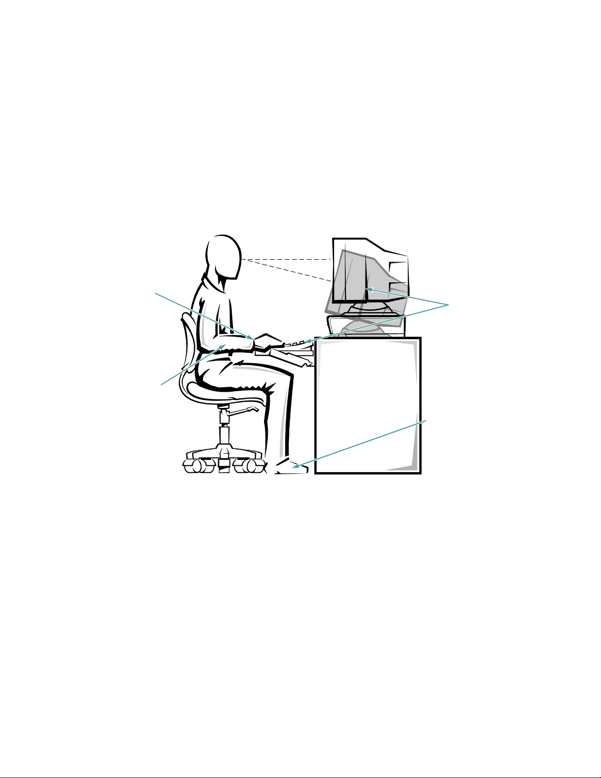
• Keep your forearms horizontal with your wrists in a
neutral, comfortable position while using the keyboard or mouse.
• Always leave space to rest your hands while using
the keyboard or mouse.
• Let your upper arms hang naturally at your sides.
• Sit erect, with your feet resting on the floor and your
thighs level.
monitor screen at eye level
wrists relaxed and flat
arms at desk level
• When sitting, make sure the weight of your legs is on
your feet and not on the front of your chair seat.
Adjust your chair’s height or use a footrest, if necessary, to maintain proper posture.
• Vary your work activities. Try to organize your work
so that you do not have to type for more than a
minute or so at a time without stopping. When you
stop typing, try to do things that use both hands.
monitor and keyboard
positioned directly in
front of user
feet flat on the floor
iv
Page 5

When Working Inside Your Computer
Before you remove the computer cover, perform the following steps in the sequence indicated:
1. Turn off your computer and any peripherals.
2. Disconnect your computer and peripherals from
their power sources. Also disconnect any telephone or telecommunications lines from the
computer.
Doing so reduces the potential for personal injury or
shock.
3. Touch an unpainted metal surface at the back of
the computer chassis (such as the power supply)
before touching anything inside your computer.
While you work, periodically touch an unpainted
metal surface on the computer chassis to dissipate
any static electricity that might harm internal
components.
In addition, take note of these safety guidelines when
appropriate:
• Do not attempt to service the computer system your-
self, except as explained in this guide and elsewhere
in Dell documentation. Always follow installation
and servicing instructions closely.
• When removing a component from the system board
or disconnecting a peripheral device from the computer, wait 5 seconds after turning off the system
before removing the component or disconnecting the
device to avoid possible damage to the system board.
• When you disconnect a cable, pull on its connector
or on its strain-relief loop, not on the cable itself. As
you pull connectors apart, keep them evenly aligned
to avoid bending any connector pins. Also, before
you connect a cable, make sure both connectors are
correctly oriented and aligned.
• Handle components and cards with care. Don’t touch
the components or contacts on a card. Hold a card by
its edges or by its metal mounting bracket. Hold a
component such as a microprocessor chip by its
edges, not by its pins.
Protecting Against Electrostatic
Discharge
Static electricity can harm delicate components inside
your computer. To prevent static damage, discharge static
electricity from your body before you touch any of your
computer’s electronic components, such as the microprocessor. You can do so by touching an unpainted metal
surface on the computer chassis.
As you continue to work inside the computer, periodically touch an unpainted metal surface to remove any
static charge your body may have accumulated.
In addition to the preceding precautions, you can also
take the following steps to prevent damage from electrostatic discharge (ESD):
• When unpacking a static-sensitive component from
its shipping carton, do not remove the component’s
antistatic packing material until you are ready to
install the component in your computer. Just before
unwrapping the antistatic packaging, be sure to discharge static electricity from your body.
• When transporting a sensitive component, first place
it in an antistatic container or packaging.
• Handle all sensitive components in a static-safe area.
If possible, use antistatic floor pads and workbench
pads.
The following caution appears throughout this document
to remind you of these precautions:
CAUTION: See “Protecting Against Electrostatic
Discharge” in the safety instructions at the front of
this guide.
v
Page 6

vi
Page 7

Preface
About This Guide
This guide is intended for anyone who uses the Dell PowerEdge 2100/180 or 2100/200 computer systems. The
guide can be used by both first-time and experienced
computer users who want to learn about the features and
operation of the systems or who want to upgrade their
computers. The chapters and appendixes are summarized
as follows:
• Everyone should read Chapter 1, “Introduction,” for
an overview of the system features, a description of
the controls and indicators on the front panel, and a
general discussion of connecting external devices to
the back panel of the computer.
• Users who want to use the utilities, the diagnostics, the
online documentation, or install drivers for their operating system should read Chapter 2.
• Everyone should read the first few sections of Chap-
ter 3, “Installing and Configuring SCSI Drivers,” to
find out which small computer system interface
(SCSI) device drivers (if any) are required for a particular system configuration. Users who need to
install and configure particular SCSI device drivers
should then read the appropriate section for their
operating system.
• Everyone should read the first several sections of
Chapter 4, “Using the System Setup Program,” to
familiarize themselves with this important program.
Only users who want to make configuration changes
to their system or who want to use the password features need to read the rest of Chapter 4.
• Everyone should read Chapter 5, “Using the EISA
Configuration Utility” whenever an Extended Industry-Standard Architecture (EISA) or IndustryStandard Architecture (ISA) expansion card is
added, removed, or repositioned in the computer.
Also, when you change the memory size, or change
settings for one of the built-in devices you must run
this utility.
• Chapter 6, “Working Inside Your Computer,” Chap-
ter 7, “Installing System Board Options,” Chapter 8,
“Installing Drives in the External Bays,” and Chapter 9, “Installing Drives in the Internal Bays,” are
intended for users who want to install or remove
options inside the computer, such as dual in-line
memory modules (DIMMs), expansion cards, or
drives.
• Appendix A, “Technical Specifications,” and
Appendix B, “Hardware Configuration Features,”
are intended primarily as reference material for users
interested in learning more about the details of the
system. Users who add internal options may need to
refer to Appendix B to change jumper settings.
• Appendix C, “Maintaining the System,” describes
preventive maintenance procedures that you should
perform regularly to keep your computer system in
top operating condition.
• Appendix D, “Regulatory Notices,” is for users who
are interested in which regulatory agencies have
tested and approved the Dell PowerEdge 2100/180
and 2100/200 systems.
• Appendix E, “Warranties and Return Policy,”
describes the warranties for Dell PowerEdge 2100/
180 and 2100/200 systems and the “Total Satisfaction” Return Policy.
• Appendix F, “Beep Codes and System Messages,”
describes the beep codes and system messages that
the system can generate when problems occur. The
information in this appendix replaces the information in Chapter 3, “Messages and Codes,” in the
Diagnostics and Troubleshooting Guide.
vii
Page 8

• The Glossary provides definitions of terms, acro-
nyms, and abbreviations used in this guide.
Warranty and Return Policy
Information
Dell Computer Corporation (“Dell”) manufactures its
hardware products from parts and components that are
new or equivalent to new in accordance with industrystandard practices. For information about the Dell
warranty for your system, see Appendix E, “Warranties
and Return Policy.”
Other Documents You May Need
In addition to this User’s Guide, the following documentation is included with your system:
• The Diagnostics and Troubleshooting Guide
includes troubleshooting procedures and instructions
for using the diskette-based diagnostics to test your
computer system.
• The Intel LANDesk Server Manager Suite, which
includes a CD-ROM containing the server manager
software, plus the following documents: LANDesk
Server Manager Setup Guide, LANDesk Server
Manager User’s Guide, LANDesk Server Control
Installation and User’s Guide, LANDesk Server
Monitor Module Installation and User’s Guide.
You may also have one or more of the following
documents.
NOTE: Documentation updates are sometimes included
with your system to describe changes to your system or
software. Always read these updates before consulting any
other documentation because the updates often contain the
latest information.
• Operating system documentation is included if you
ordered your operating system software from Dell.
This documentation describes how to install (if necessary), configure, and use your operating system
software.
• Documentation is included with any options you
purchase separately from your system. This documentation includes information that you need to
configure and install these options in your Dell computer. Installation instructions for the options are
also included in this guide.
• Technical information files—sometimes called
“readme” files—may be installed on your hard-disk
drive to provide last-minute updates about technical
changes to your system or advanced technical reference material intended for experienced users or
technicians.
Notational Conventions
The following subsections list notational conventions
used in this document.
Warnings, Cautions, and Notes
Throughout this guide, there may be blocks of text
printed in bold type within boxes or in italic type. These
blocks are warnings, cautions, and notes, and they are
used as follows:
WARNING: A WARNING indicates the potential
for bodily harm and tells you how to avoid the
problem.
CAUTION: A CAUTION indicates either potential damage to hardware or loss of data and tells
you how to avoid the problem.
viii
Page 9

Typographical Conventions
The following list defines (where appropriate) and illustrates typographical conventions used as visual cues for
specific elements of text throughout this document:
• Keycaps, the labeling that appears on the keys on a
keyboard, are enclosed in angle brackets.
Example: <Enter>
• Key combinations are series of keys to be pressed
simultaneously (unless otherwise indicated) to perform a single function.
Example: <Ctrl><Alt><Del>
• Commands presented in lowercase bold are for refer-
ence purposes only and are not intended to be typed
at that particular point in the discussion.
Example: “Use the format command to. . . .”
In contrast, commands presented in the Courier
font are intended to be typed as part of an instruction.
Example: “Type format a: to format the diskette in
drive A.”
• Filenames and directory names are presented in low-
ercase bold.
Example: autoexec.bat and c:\windows
• Syntax lines consist of a command and all its possi-
ble parameters. Commands are displayed in
lowercase bold; variable parameters (those for which
you substitute a value) are displayed in lowercase
italics; constant parameters are displayed in lowercase bold. The brackets indicate items that are
optional.
Example: del [drive:] [path]filename [/p]
• Command lines consist of a command and may
include one or more of the command’s possible
parameters. Command lines are presented in the
Courier font.
Example:
• Screen text is text that appears on the screen of your
monitor or display. It can be a system message, for
example, or it can be text that you are instructed to
type as part of a command (referred to as a command
line). Screen text is presented in the Courier
font.
Example: The following message appears on your
screen:
No boot device available
Example: “Type md c:\dos, and then press
<Enter>.”
• Variables are symbols for which you substitute a
value. They are presented in italics.
Example: DIMMn (where n represents the DIMM
number)
ix
Page 10

x
Page 11

Chapter 1
Introduction
®
Dell
are high-speed, upgradable server systems designed
around the Intel® Pentium® Pro family of microprocessors. The PowerEdge 2100 systems provide both
Extended Industry-Standard Architecture (EISA) and
high-performance Peripheral Component Interconnect (PCI)
expansion slots to allow for future expansion of your system.
This chapter describes the major hardware and software
features of the computer, provides information about the
indicators and controls on the computer’s front panel, and
discusses connecting external devices to the computer.
PowerEdge® 2100/180 and 2100/200 systems
System Features
The PowerEdge 2100/180 and 2100/200 systems offer
the following major features:
• A Pentium Pro microprocessor with an internal oper-
ating frequency of 180 megahertz (MHz) in the
PowerEdge 2100/180 and 200 MHz in the PowerEdge
2100/200. The external bus speeds of the PowerEdge
2100/180 and PowerEdge 2100/200 are 60 MHz and
66 MHz (respectively).
NOTE: The microprocessor module is installed in a
zero insertion force (ZIF) socket on the system
board, allowing you to upgrade to a faster, more
powerful microprocessor as your processing needs
increase.
The Pentium Pro microprocessor module includes
separate processor and cache memory chips
(256kilobytes [KB]) in a single module. The
Pentium Pro microprocessor features Dynamic
Execution, which combines three processing
techniques:
— Multiple branch prediction—the processor
anticipates jumps in the instruction flow and
where the next instruction can be found in
memory.
— Data flow analysis—the processor determines
which instructions are ready for processing and
which are waiting for results from other instructions. The processor then schedules instruction
execution to minimize idle time.
— Speculative execution—the processor executes
instructions according to the optimized schedule
for maximum processor performance and
efficiency.
• Cache memory (internal to the Pentium Pro module)
that provides 256 KB of static random-access memory (SRAM). Cache memory enhances the speed of
many microprocessor operations by storing the most
recently accessed contents of system memory.
• A minimum of 16 megabytes (MB) of system mem-
ory, upgradable to a maximum of 512 MB by
installing combinations of 16-, 32-, and 128-MB
buffered, extended data output (EDO), dual in-line
memory modules (DIMMs) in the four DIMM sockets on the system board.
The buffered 72-bit wide EDO DIMMs installed in
PowerEdge 2100 systems support error correction
code (ECC) to check for and correct memory errors.
ECC is performed by the memory controller in the
system chip set.
Introduction 1-11
Page 12

• A basic input/output system (BIOS) that resides in
flash memory on the EISA bus and can be upgraded
by diskette if required.
The system board includes the following built-in
features:
• Three EISA and three PCI expansion-card connec-
tors, located on the system board. A separate
expansion-card slot is available for each EISA and
PCI expansion-card connector; there are no shared
expansion slots.
• An integrated video graphics array (VGA)-
compatible video subsystem with an ATI mach64
(264VT) PCI video controller connected to the PCI
local bus. The standard video subsystem includes
1MB of video memory. Maximum resolutions (noninterlaced) are 640 x 480 pixels (16.7 million colors)
and 800 x 600 pixels (65,536 colors). Maximum resolution (interlaced) is 1024 x 768 pixels (256
colors).
• An integrated National Semiconductor PC87336
super input/output (I/O) controller that controls the
bidirectional parallel port, two serial ports, and the
diskette drive in the externally accessible front bay.
The super I/O controller resides on the EISA bus.
The parallel port can be set to operate in the following
modes via the Parallel Mode category in the System
Setup program: output-only (AT-compatible), bidirectional (Personal System/2 [PS/2]-compatible), or
extended capabilities port (ECP).
• An integrated Adaptec AIC-7880 ultra (fast-20)
wide, small computer system interface (SCSI) controller. The built-in SCSI controller supports up to
two externally accessible SCSI devices in the top
bays and up to three SCSI hard-disk drives in the
internal bays. The SCSI interface connects to supported devices via a 68-conductor cable. The
integrated SCSI controller resides on the PCI local
bus for optimum performance.
• Integrated server management circuitry that monitors
operation of the system fan as well as critical system
voltages and temperatures. The integrated server management circuitry works in conjunction with the Intel
LANDesk® Server Manager suite. See the Preface
earlier in this guide for a list of documents that
describe installation and use of the LANDesk Server
Manager suite.
• Integrated system board support for the Upgrade
Server Management Card which provides improved
local and remote server management.
• A PS/2-style keyboard port and a PS/2-compatible
mouse port.
Standard PowerEdge 2100 systems include a diskette
drive and a SCSI CD-ROM drive installed in the externally accessible bays and at least one SCSI hard-disk
drive installed in the internal bays.
The following software is included with your Dell computer system:
• Video drivers for displaying many popular applica-
tion programs in high-resolution modes. For more
information on these drivers, see Chapter 2, “Using
the Dell Server Assistant CD.”
• SCSI device drivers that allow your operating sys-
tem to communicate with devices attached to the
built-in SCSI subsystem. For more information on
these drivers, see Chapter 3, “Installing and Configuring SCSI Drivers.”
• The System Setup program for quickly viewing and
changing the system configuration information for
your computer. For more information on this program, see Chapter 4, “Using the System Setup
Program.”
• The EISA Configuration Utility, which allows you to
configure installed EISA expansion cards through
software rather than by hand. (You must also run the
EISA Configuration Utility when installing or
removing Industry-Standard Architecture [ISA]
cards.) For more information, see Chapter 5, “Using
the EISA Configuration Utility.”
• Enhanced security features available through either
the System Setup program or the EISA Configuration Utility include a user password and a supervisor
password.
• Diagnostics for evaluating your computer’s compo-
nents and devices. For information on using the
diagnostics, see Chapter 2, “Using the Dell Server
Assistant CD” or see the chapter titled “Running the
Diskette-Based Diagnostics” in your Diagnostics and
Troubleshooting Guide.
1-12 Dell PowerEdge 2100/180 and 2100/200 Systems User’s Guide
Page 13
Supported Operating Systems
Dell supports the following network operating systems
for use on PowerEdge 2100 systems:
• Microsoft
• Novell
Operating system software is not included with
PowerEdge 2100 systems. If you purchase the operating system software from Dell, installation
instructions are included on the CD-ROM with the
operating system software.
NOTE: Installation services and support for other operating systems are available through Dell Plus. Contact
Dell for more information.
®
Windows NT® Server 3.51 and 4.x
®
NetWare® 3.12, 4.x (and later versions)
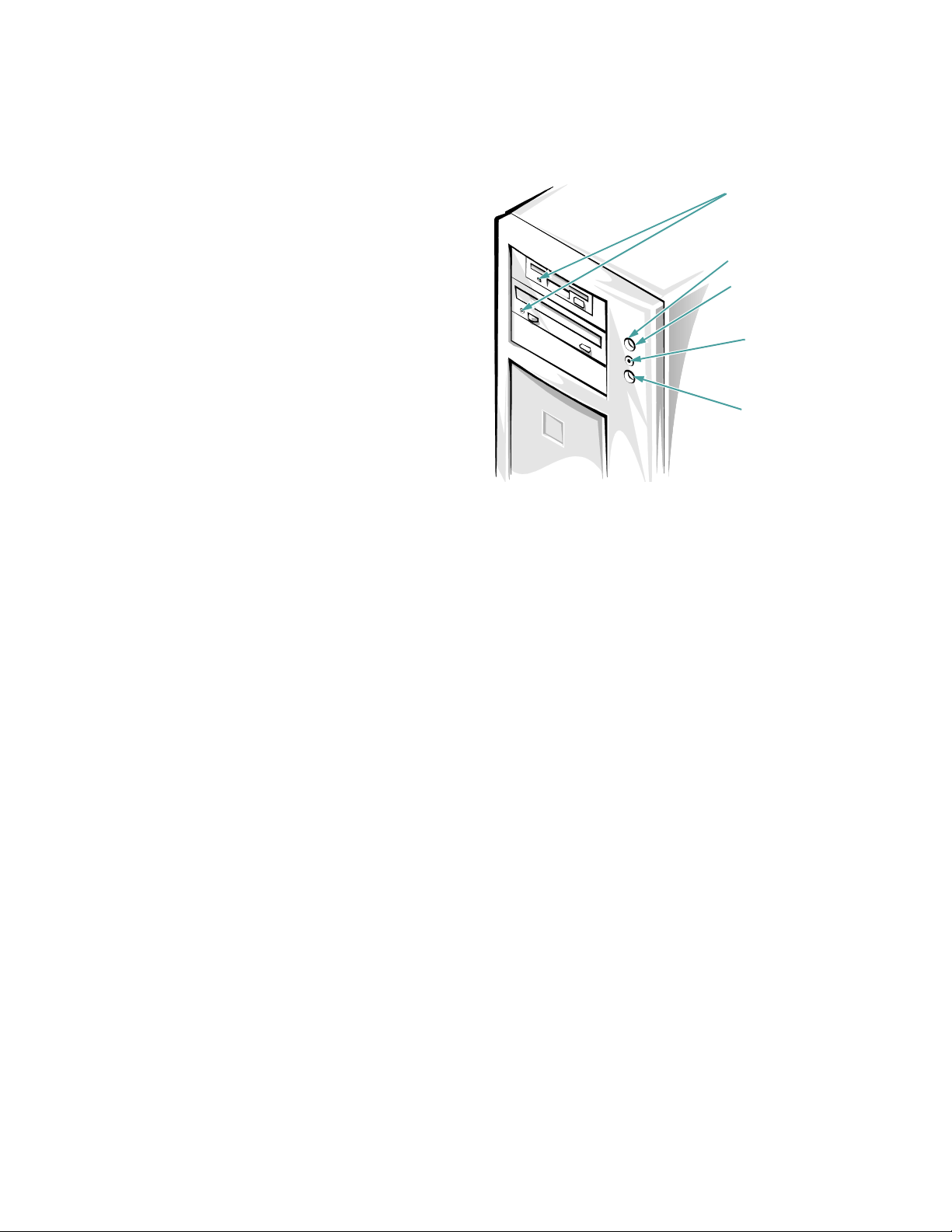
drive access
indicators
power button
power indicator
(inside power button)
drive access
indicator
reset button
Front Panel
The following controls and indicators are located on the
computer’s front panel (see Figure 1-1):
• The power button on the front panel controls the alternat-
ing current (AC) input power to the system’s power
supply.
• The green power indicator in the center of the power
button lights when the power supply is turned on and the
system is receiving direct current (DC) power.
• When any SCSI device is being accessed, the drive
access indicator on the front panel lights.
• The reset button on the front panel saves wear and tear on
system components by allowing you to reboot (restart)
the computer without turning the power off and then on
again. For more information about using the reset button,
see “Reset Button” in Chapter 4.
NOTE: The power button and the reset button are
recessed into the computer’s front panel to prevent
accidentally turning off or resetting the computer
and losing valuable data.
Figure 1-1. Front Panel
Connecting External Devices
You can connect various external devices, such as a
mouse and printer, to the I/O ports and connectors on the
computer’s back panel. The system BIOS detects the
presence of external devices when you boot or reboot
your system. When connecting external devices to your
computer, follow these guidelines:
• Check the documentation that accompanied the
device for specific installation and configuration
instructions.
For example, most devices must be connected to a
particular I/O port or connector to operate properly.
Also, external devices like a mouse or printer usually
require you to load software files called device drivers
into memory before they will work. These software drivers help the computer recognize an external device and
direct its operation. Device drivers of this type are normally included with your operating system software.
Introduction 1-13
Page 14
• Always attach external devices while your computer is
turned off. Then turn on any external devices before turn-
ing on the computer unless the documentation for the
device specifies otherwise. (If the computer does not
seem to recognize the device, try turning on the computer
before turning on the device.)
For information about enabling, disabling, or configuring
I/O ports and connectors, see Chapter 4, “Using the System Setup Program,” or Chapter 5, “Using the EISA
Configuration Utility.” For detailed descriptions and
illustrations of each port and connector on the I/O panel,
see “I/O Ports and Connectors” in Appendix B.
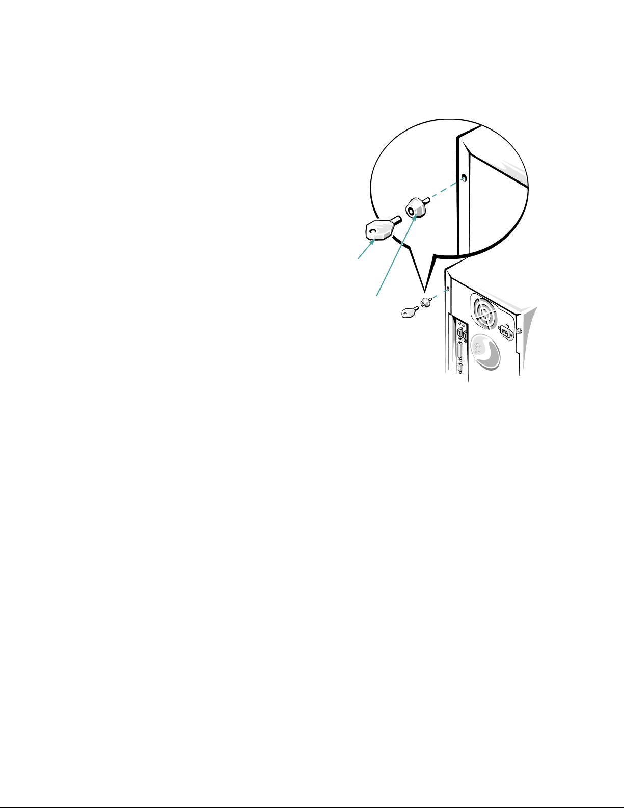
key
Preventing Unauthorized Access
Inside the Computer
To prevent unauthorized access to the inside of the computer, you can replace one of the screws that secure the
cover to the chassis with a special keylock screw that is
included with the system. A key, provided with the system, is required to install or remove the special keylock
screw, thus preventing anyone without access to the tool
from removing the computer cover (see Figure 1-2).
keylock
screw
Figure 1-2. Security Keylock
Getting Help
If at any time you don’t understand a procedure described
in this guide, or if your system does not perform as
expected, Dell provides a number of tools to help you.
For more information on these help tools, see the chapter
titled “Getting Help” in your Diagnostics and Trouble-
shooting Guide.
1-14 Dell PowerEdge 2100/180 and 2100/200 Systems User’s Guide
Page 15

Chapter 2
Using the Dell Server Assistant CD
This chapter describes the bootable Dell Server Assis-
tant CD and tells you how to use the utilities, diagnostics,
documentation, drivers, and other items included on the
CD. This chapter also describes how to install the video
drivers for supported operating systems and how to use
the asset tag utility provided on the CD.
Booting the CD
The system must be running to insert the CD. To boot
the CD, insert it into the PowerEdge 2100 system’s
CD-ROM drive and press the reset button. When the system boots, the CD main menu appears.
If the CD does not boot, check the following:
• In the System Setup program, the Onboard SCSI cat-
egory must be set to Scanned and the Boot Sequence
category must be set to A: then C: (see Chapter 4,
“Using the System Setup Program”).
• In the SCSISelect Utility, the Bios Support for Boot-
able CD-ROM category must be set to Enabled (see
Chapter 3, “Installing and Configuring SCSI
Drivers”).
CD Main Menu
The main menu of the CD includes the following categories, each of which has one or more options. The
subsections that follow describe the options within each
main menu category. The main menu on your CD may
contain additional options.
Choose Language
• Deutsch
• English
• Espanol
• Francais
Configure the System
• Run EISA Configuration Utility
Run System Utilities
• Run System Diagnostics
Use Online Manuals
• Use the System User’s Guide
Create Diskettes
• Create Blank Formatted Diskette
• Create Utility Diskettes
— Create EISA Configuration Utility Diskette
— Create System Utility Diskette
• Create Operating System Support Diskettes
— Create Windows NT Server 3.51 Diskettes
– Create Driver Diskette
— Create Netware 4.x Diskettes
– Create Driver Diskette
– Create Adaptec EZ-SCSI Diskette
— Create Netware 3.12 Diskettes
– Create Driver Diskette
— Create Adaptec EZ-SCSI Diskette
Using the Dell Server Assistant CD 2-15
Page 16

Choose Language
When the system boots, you are given the option of
choosing one of the following languages for the menus,
help screens, messages, and online documentation:
• German
• English
• Spanish
• French
After you choose a language, the main menu appears in
the chosen language.
Configure the System
The options within the Configure the System category
are used for configuring your system. The following subsections describe the options available in this category.
Run EISA Configuration Utility
This option allows you to run the EISA Configuration
Utility directly from the CD to ensure that the system is
properly configured for the remaining configuration
steps. See Chapter 5, “Using the EISA Configuration
Utility,” for instructions on running the EISA Configuration Utility.
In addition to being able to run the EISA Configuration
Utility directly from the CD, you can create a diskette (or
diskettes) and run the EISA Configuration Utility from
the diskette(s).
Run System Utilities
The options within the Run System Utilities category
allow you to run the system diagnostics and any other
utilities available on your CD. The following subsection
describes the option available in this category.
Run System Diagnostics
This option allows you to run the system hardware
diagnostics directly from the CD. Before running the
diagnostics from the CD, you should make a blank formatted diskette and insert it in the diskette drive so the
diagnostics programs can record critical messages and
information as they execute. See “Create Blank Formatted Diskette” found later in this chapter for instructions
on creating the necessary diskette. The system hardware
diagnostics are described in the Diagnostics and Trouble-
shooting Guide.
Use Online Manuals
The Use Online Manuals category includes all available
online manuals. Selecting one of the online manuals
launches the Adobe Acrobat viewer (included on the CD)
and allows you to view or print the online manual in the
language that you selected earlier.
NOTE: You can also copy the portable document format
(PDF) files from the CD and use them under your native
operating system.
The following subsections describe the options available
in this category.
Use the System User’s Guide
This option allows you to view or print the system User’s
Guide.
Create Diskettes
The Create Diskettes category allows you to create diskettes of system utilities and operating system-specific
drivers as well as blank formatted diskettes. The following subsections describe the options available in this
category.
Create Blank Formatted Diskette
This option allows you to create blank formatted
diskettes.
Create Utility Diskettes
This option allows you to create bootable utility diskettes
for running the EISA Configuration Utility and the asset
tag utility. The following subsections describe the choices
available with this option.
2-16 Dell PowerEdge 2100/180 and 2100/200 Systems User’s Guide
Page 17

Create EISA Configuration Utility Diskette
This option allows you to create a bootable EISA Configuration Utility diskette (or diskettes). Dell recommends
running the EISA Configuration Utility from a diskette
so you can copy your configuration information to the
diskette any time you change system configuration
parameters.
Create System Utility Diskette
This option allows you to copy the asset tag utility from
the CD to a bootable diskette. For instructions on running
the asset tag utility, see “Asset Tag Utility” found later in
this chapter.
Create Operating System Support
Diskettes
This option allows you to create a diskette that contains
the software drivers for a specific operating system. You
can create a diskette of drivers for one of the following
supported operating systems:
• Microsoft Windows NT Server 3.51
• Novell NetWare 4.x (and 4.1 SMP)
• Novell NetWare 3.12
Drivers available on the CD include:
• Video drivers
• Small computer system interface (SCSI) drivers
• Network interface controller (NIC) drivers
NOTE: The Novell NetWare operating system does
not use video drivers, so they are not included when
you create a diskette of drivers for NetWare.
The following subsections describe the options available
in this category.
Create Windows NT Server 3.51 Diskettes
This option allows you to create a driver diskette for use
with Windows NT Server 3.51.
Create Driver Diskette
This option allows you to create a diskette that contains
video, SCSI, and NIC drivers for the Windows NT Server 3.51 operating system.
NOTE: Be sure to use the SCSI Driver diskettes created
from the Dell Server Assistant CD rather than the SCSI
drivers provided with the operating system.
Create NetWare 4.x Diskettes
This option allows you to create a driver diskette and an
Adaptec EZ-SCSI configuration utility diskette for use
with the Novell NetWare 4.x operating system. The following subsections describe the choices available with
this option.
Create Driver Diskette
This option allows you to create a diskette that contains
SCSI and NIC drivers for the Novell NetWare 4.x operating system.
NOTE: Be sure to use the SCSI Driver diskettes created
from the Dell Server Assistant CD rather than the SCSI
drivers provided with the operating system.
Create Adaptec EZ-SCSI Diskette
This option allows you to create a diskette that contains
the configuration utility for Adaptec SCSI controllers.
The configuration utility works with the optional
Adaptec AHA-2940UW and the built-in Adaptec 78xx
series SCSI controllers when used with the Novell NetWare 4.x operating system.
Create NetWare 3.12 Diskettes
This option allows you to create a driver diskette and an
Adaptec EZ-SCSI configuration utility diskette for use
with the Novell NetWare 3.12 operating system. The following subsections describe the choices available with
this option.
Using the Dell Server Assistant CD 2-17
Page 18

Create Driver Diskette
This option allows you to create a diskette that contains
SCSI and NIC drivers for the Novell NetWare 3.12 operating system.
NOTE: Be sure to use the SCSI Driver diskettes created
from the Dell Server Assistant CD rather than the SCSI
drivers provided with the operating system.
Create Adaptec EZ-SCSI Diskette
This option allows you to create a diskette that contains
the configuration utility for Adaptec SCSI controllers.
The configuration utility works with the optional
Adaptec AHA-2940UW and the built-in Adaptec 78xx
series SCSI controllers when used with the Novell NetWare 3.12 operating system.
Video Drivers
You will need to install the video drivers for the operating
system you install on your PowerEdge 2100 system,
unless they were installed by Dell. Use the following procedure to install the video drivers for Windows NT .
NetWare provides a textual interface and does not require
video drivers.
Installing Video Drivers for
Windows NT 3.51
See “Create Operating System Support Diskettes” found
earlier in this chapter for instructions on making a diskette of software drivers for Windows NT 3.51. After you
make the diskette of drivers, use the following procedure
to install the video drivers:
1. Insert the diskette of drivers into the diskette
drive on your system.
2. Run the Windows NT Display program located in
the Control Panel in the Main group.
3. Select Change Display Type.
4. Select Change from the display options; then
select Other.
5. When prompted for the correct path, type
a:\ATI and press <Enter>.
If the diskette is not in drive A, change the drive letter designation as appropriate.
After the system reads the diskette, it displays the
ATI Graphics Accelerators option.
6. Select the ATI Graphics Accelerators option;
then click Install.
Confirm your choice when prompted to do so, and
all appropriate files will be copied to the hard-disk
drive.
7. Restart Windows NT.
The system will start up using the ATI mach64 drivers in 640 x 480 mode and display an application that
allows you to choose a resolution.
The maximum resolutions supported by the built-in
ATI mach 64 video controller with 1 MB of video
memory are 640 x 480 pixels (16.7 million colors)
and 800 x 600 pixels (65,536 colors) (noninterlaced); and 1024 x 768 pixels (256 colors)
(interlaced).
NOTE: If you select a resolution that is not supported by the ATI mach64 (264VT) video controller
with 1 MB of memory, the operating system will substitute 640 x 480 in 256 colors.
Asset Tag Utility
The Asset Tag utility allows you to enter an asset tag
number for your computer. The default System Setup
screens (see Figure 4-1, for example) do not show the
asset tag number unless you enter one using this utility.
NOTE: The Asset Tag utility works only on systems running MS-DOS®.
2-18 Dell PowerEdge 2100/180 and 2100/200 Systems User’s Guide
Page 19

Using the Asset Tag Utility
Use the following procedure to create a system utility
diskette and boot the system:
1. If you have not already done so, create a bootable
system utility diskette from the CD.
2. Insert the diskette in drive A, and reboot the
system.
After you boot the system with the system utility diskette, you can use the Asset Tag utility to enter an
asset tag number that you or your organization
assign to the computer. You can also use the Asset
Tag utility to reenter the computer’s service tag number if that becomes necessary.
You can view the asset tag number using the System
Setup program as described in Chapter 4, “Using the
System Setup Program.”
Assigning and Deleting an Asset Tag
Number
An asset tag number can have up to ten characters; any
combination of characters, excluding spaces, is valid. To
assign or change an asset tag number, type asset and a
space followed by the new number; then press <Enter>.
For example, type the following command line and press
<Enter>:
asset 1234567890
When prompted to verify the asset tag number, type y
and press <Enter>. The system then displays the new or
modified asset tag number and the service tag number.
To delete the asset tag number without assigning a new
one, type asset /d and press <Enter>.
Table 2-1 lists the command line options you can use
with the Asset Tag utility. To use one of these options,
type asset and a space followed by the option.
.
Table 2-1. Asset Tag Command-Line Options
Asset Tag Option Description
/d Deletes the asset tag
number
/? Displays the Asset Tag
utility help screen
Using the Dell Server Assistant CD 2-19
Page 20

2-20 Dell PowerEdge 2100/180 and 2100/200 Systems User’s Guide
Page 21

Chapter 3
Installing and Configuring SCSI Drivers
This chapter describes how to install and configure the
Dell small computer system interface (SCSI) device drivers included with your Dell PowerEdge 2100 computer
system. These device drivers are designed to work with the
Adaptec AIC-7880 Ultra/Wide SCSI controller chip on the
system board.
Both the built-in AIC-7880 and the optional
AHA-2940UW SCSI controller card are all part of the
Adaptec 78xx series of SCSI controllers, and use the 78xx
series of SCSI drivers Dell provides. The Adaptec SCSI
basic input/output system (BIOS), which is stored in your
computer system’s flash memory or on the optional
AHA-2940UW SCSI controller card, links these SCSI
device drivers to the built-in AIC-7880 or the optional
AHA-2940UW SCSI controller card.
For instructions on installing SCSI hardware devices such
as hard-disk drives, tape drives, or CD-ROM drives, see
Chapter 8, “Installing Drives in the External Bays,” and
Chapter 9, “Installing Drives in the Internal Bays.” For
information on SCSI configuration guidelines (SCSI identification [ID] numbers and termination requirements), see
“SCSI Configuration Guidelines” in Chapter 9.
After the SCSI devices you plan to use are installed, you
may need to install and configure one or more SCSI device
drivers so that your SCSI devices can communicate with
your operating system.
SCSI device drivers are provided for the following operating systems:
• Microsoft Windows NT Server 3.51
• Novell NetWare 3.12 and 4.x
See Chapter 2, “Using the Dell Server Assistant CD,” for
instructions on creating a diskette of drivers for your
operating system. For instructions on configuring the
SCSI device drivers, see the appropriate sections in this
chapter.
The readme.txt File
The readme.txt file that is included with your SCSI
device drivers (in the \scsi directory on the CD) provides
updates to the information in this chapter.
Use the editor included with your operating system to
view or print the readme.txt file or any other readme
file.
The SCSISelect Utility
The BIOS for the built-in Adaptec AIC-7880 controller
includes the menu-driven SCSISelect configuration utility, which allows you to change SCSI controller settings
without opening the computer. SCSISelect also contains
SCSI disk utilities that let you low-level format or verify
the disk media of your SCSI hard-disk drives.
SCSISelect Default Settings
Default settings for the optional Adaptec AHA-2940UW
SCSI controller and the built-in AIC-7880 SCSI controller are shown in Table 3-1. These default settings are
appropriate for most Peripheral Component Interconnect
(PCI) systems. Run SCSISelect only if you need to
change any of the default settings.
NOTE: The term host adapter is used throughout this
chapter to refer to the built-in AIC-7880 SCSI controller
or the optional AHA-2940UW SCSI controller card.
For situations in which you might want or need to change
the settings, see the descriptions of each setting in the following subsections. To change any of the default settings
or to format or verify a disk, see “Starting the SCSISelect
Utility” found later in this chapter.
Installing and Configuring SCSI Drivers 3-21
Page 22

Table 3-1. Default SCSI Controller Settings
Setting Default
SCSI Bus Interface Definitions:
Host Adapter SCSI ID 7
SCSI Parity Checking Enabled
Host Adapter SCSI Termination Low On/High
On
Boot Device Options:
Boot Target ID 0
Boot LUN Number 0
SCSI Device/Configuration:
Initiate Sync Negotiation Yes (Enabled)
Maximum Sync Transfer Rate 40 Mb/sec
Enable Disconnection Yes (Enabled)
Initiate Wide Negotiation Yes (Enabled)
Send Start Unit Command Yes (Enabled)
Basic Host Adapter Settings
The basic host adapter settings are the SCSISelect settings most likely to require modification.
• Host Adapter SCSI ID. This option sets the host
adapter’s SCSI ID. The default setting is SCSI ID 7,
which allows the host adapter to support narrow
SCSI devices in addition to wide SCSI devices. Dell
recommends that you leave the host adapter set to
SCSI ID 7.
• SCSI Parity Checking. This option determines
whether the host adapter verifies the accuracy of data
transfer on the SCSI bus. The default setting is
Enabled. You should disable SCSI Parity Checking
if any SCSI device connected to the host adapter
does not support SCSI parity; otherwise, leave it
enabled. Most SCSI devices support SCSI parity. If
you are unsure if a device supports SCSI parity, consult the documentation for the device.
• Host Adapter SCSI Termination. This option sets ter-
mination on the host adapter. The default setting for
all Adaptec 78xx series host adapters is Low On/
High On. Dell recommends that you leave this
option set to the default.
Advanced Host Adapter:
Host Adapter BIOS Enabled
Support Removable Disks Under
BIOS as Fixed Disks
Extended BIOS Translation for
DOS Drivers > 1 GB
Display <Ctrl><a> Message
During BIOS Initialization
Multiple LUN Support Disabled
BIOS Support for Bootable
CD-ROM
BIOS Support for INT 13
Extensions
Support for Ultra SCSI Speed Enabled
NOTE: For the full name of an abbreviation or acronym
used in this table, see the Glossary.
Boot Only
Enabled
Enabled
Enabled
Enabled
Boot Device Settings
The boot device settings allow you to specify the device
from which to boot your computer.
• Boot Target ID. This option specifies the SCSI ID of
the device from which you wish to boot your system.
The default setting is SCSI ID 0. The SCSI ID
selected here must correspond to the ID configured
on the boot device.
• Boot LUN Number. If your boot device has multiple
logical unit numbers (LUNs) and Multiple LUN
Support is enabled (see “Advanced Host Adapter
Settings” found later in this section), this option
allows you to specify a particular LUN from which
to boot on your boot device. The default setting is
LUN 0.
3-22 Dell PowerEdge 2100/180 and 2100/200 Systems User’s Guide
Page 23

SCSI Device Settings
The SCSI device settings allow you to configure certain
parameters for each device on the SCSI bus. To configure
a specific device, you must know the SCSI ID assigned to
that device. If you are not sure of the SCSI ID, see
“Using the SCSI Disk Utilities” found later in this
section.
• Initiate Sync Negotiation. This option determines
whether the host adapter initiates synchronous data
transfer negotiation (sync negotiation) between itself
and the device. The default setting is Yes.
The host adapter always responds to sync negotiation if the SCSI device initiates it. If neither the host
adapter nor the SCSI device initiates sync negotiation, data is transferred asynchronously.
Normally, you should leave the Initiate Sync Negotiation setting enabled, because most SCSI devices
support sync negotiation and because it allows for
faster data transfer.
NOTE: Some older SCSI-1 devices do not support
sync negotiation. This may cause your computer to
operate erratically or hang if Initiate Sync Negotiation is set to Yes. Set Initiate Sync Negotiation to No
for these devices.
• Maximum Sync Transfer Rate. This option sets the
maximum synchronous data transfer rate that the
host adapter supports. The host adapter supports
rates up to the maximum of 40 megabytes per second
(MB/sec). The default setting is 40 MB/sec (the
maximum).
If the host adapter is set to not negotiate for synchronous data transfer, the maximum synchronous
transfer rate is the maximum rate that the host
adapter accepts from the device during negotiation.
(This is standard SCSI protocol.)
• Enable Disconnection. This option (sometimes
called disconnect/reconnect) determines whether the
host adapter allows the SCSI device to disconnect
from the SCSI bus. Enabling disconnection allows
the host adapter to perform other operations on the
SCSI bus while the SCSI device is temporarily disconnected. The default setting is Yes.
Leave Enable Disconnection set to Yes if two or
more SCSI devices are connected to the host adapter.
This optimizes SCSI bus performance. If only one
SCSI device is connected to the host adapter, set
Enable Disconnection to No to achieve slightly better performance.
• Initiate Wide Negotiation. This option determines
whether the host adapter attempts 16-bit data transfer
instead of 8-bit data transfer. The default setting is
Yes.
NOTE: Some 8-bit SCSI devices may have trouble
handling wide negotiation, which may result in
erratic behavior or a hang condition. For these
devices, set Initiate Wide Negotiation to No.
When this option is set to Yes, the host adapter
attempts 16-bit transfer. When this option is set to
No, 8-bit data transfer is used unless the SCSI device
itself requests wide negotiation. The effective transfer rate is doubled when 16-bit data transfer is used
because the data path for wide SCSI is twice the size
of normal 8-bit SCSI.
• Send Start Unit Command. This option determines
whether the start unit command is sent to the SCSI
device at boot. The default setting is Yes.
Setting this option to Yes reduces the load on your
computer’s power supply by allowing the host
adapter to start SCSI devices one at a time when you
boot your computer. When this option is set to No,
the devices are allowed to start at the same time.
Most devices require you to set a jumper before they
can respond to this command.
NOTE: For many devices, if Send Start Unit Command is set to Yes, the boot time will vary depending
on how long it takes each drive to start.
Advanced Host Adapter Settings
The advanced host adapter settings should not be
changed unless absolutely necessary. Dell sets these values and changing them may cause conflicts with the
SCSI devices.
• Host Adapter BIOS. This option enables or disables
the host adapter BIOS. The default setting is
Enabled.
NOTE: Several SCSISelect options are not valid
unless the host adapter BIOS is enabled.
If you are booting from a SCSI hard-disk drive connected to the host adapter, the BIOS must be enabled.
Installing and Configuring SCSI Drivers 3-23
Page 24

You should disable the host adapter BIOS if the
peripherals on the SCSI bus (for example, CD-ROM
drives) are all controlled by device drivers and do not
need the BIOS.
• Support Removable Disks Under BIOS as Fixed
Disks. This option controls which removable-media
drives are supported by the host adapter BIOS. The
default setting is Boot Only. The following choices
are available.
CAUTION: If a removable-media SCSI device is
controlled by the host adapter BIOS, do not
remove the media while the drive is on or you may
lose data. If you want to be able to remove media
while the drive is on, install your removablemedia device driver and set this option to
Disabled.
— Boot Only. Only the removable-media drive
designated as the boot device is treated as a
hard-disk drive.
— All Disks. All removable-media drives sup-
ported by the BIOS are treated as hard-disk
drives.
— Disabled. No removable-media drives are
treated as hard-disk drives. In this situation,
software drivers are needed because the drives
are not controlled by the BIOS.
• Extended BIOS Translation for DO S Drives >1GB.
This option determines whether extended translation
is available for SCSI hard-disk drives with capacities
greater than 1 gigabyte (GB). The default setting is
Enabled.
CAUTION: Back up your hard-disk drive
before you change the translation scheme. All
data is erased when you change from one
translation scheme to another.
large as 8GB under the MS-DOS operating system
with a maximum partition size of 2 GB.
Extended BIOS translation is used only with
MS-DOS 5.0 or later. It is not necessary to enable
this if you are using another operating system such
as Novell NetWare.
When you partition a hard-disk drive larger than
1GB, use the MS-DOS fdisk utility as you normally
would. Because the cylinder size increases to 8 MB
under extended translation, the partition size you
choose must be a multiple of 8 MB. If you request a
size that is not a multiple of 8 MB, fdisk rounds up
to the nearest whole multiple of 8 MB.
• Display <Ctrl><a> Message During BIOS Initializa-
tion. This option determines whether the Press
<Ctrl><a> for SCSISelect (TM) Utility! message appears on your screen during system
start-up. The default setting is Enabled. If this setting
is disabled, you can still run the SCSISelect utility by
pressing <Ctrl><a> after the host adapter BIOS banner appears.
• Multiple LUN Support. This option determines
whether your system supports booting from a SCSI
device that has multiple LUNs. The default setting is
Disabled. Enable this option if your boot device has
multiple LUNs.
• BIOS Support for Bootable CD-ROM. This option
determines whether the host adapter BIOS provides
support for booting from a CD-ROM drive. The
default setting is Enabled.
• BIOS Support for INT 13 Extensions. This option
determines whether the host adapter BIOS supports
disks with more than 1024 cylinders. The default setting is Enabled.
• Support for ULTRA SCSI Speed. This option deter-
mines whether the host adapter supports the fast
transfer rates (20.0 to 40.0 megabits per second
[Mbps]). The default setting is Enabled.
The standard translation scheme for SCSI host
adapters provides a maximum accessible capacity of
1 GB. To support hard-disk drives larger than 1 GB,
the 78xx series host adapters include an extended
translation scheme that supports hard-disk drives as
3-24 Dell PowerEdge 2100/180 and 2100/200 Systems User’s Guide
Starting the SCSISelect Utility
You can start the SCSISelect utility by pressing
<Ctrl><a> when the following prompt appears briefly at
boot time:
Press <Ctrl><a> for SCSISelect (TM)
Utility!
Page 25

The first menu displays the Configure/View Host
Adapter Settings and SCSI Disk Utilities options.
Using SCSISelect Menus
SCSISelect uses menus to list options you can select. To
select an option, use the up- and down-arrow keys to
move the cursor to the option; then press <Enter>.
In some cases, selecting an option displays another menu.
You can return to the previous menu at any time by pressing <Esc>. To restore the original SCSISelect default
values, press <F6>.
Using the SCSI Disk Utilities
To access the SCSI disk utilities, select the SCSI Disk
Utilities option from the menu that appears when you
start SCSISelect. Once the option is selected, SCSISelect
immediately scans the SCSI bus (to determine the
devices installed) and displays a list of all SCSI IDs and
the devices assigned to each ID.
When you select a specific ID and device, a small menu
appears, displaying the Format Disk and Verify Disk
Media options.
• Format Disk. This option runs a utility that allows
you to perform a low-level format on a hard-disk
drive. Most SCSI disk drives are formatted at the
factory and do not need to be formatted again. The
Adaptec Format Disk utility is compatible with the
vast majority of SCSI disk drives.
.
CAUTION: The Format Disk option destroys
all data on the hard-disk drive.
• Verify Disk Media. This option runs a utility that
allows you to scan the media of a hard-disk drive for
defects. If the utility finds bad blocks on the media, it
prompts you to reassign them; if you select Yes,
those blocks are no longer used. You can press
<Esc> at any time to exit the utility.
Exiting SCSISelect
To exit SCSISelect, press <Esc> until a message prompts
you to exit. (If you changed any 78xx series host adapter
settings, you are prompted to save the changes before you
exit.) At the prompt, select Yes to exit, and then press any
key to reboot the computer. Any changes you made in
SCSISelect take effect after the computer boots. (You can
select No at the prompt if you are not ready to exit
SCSISelect.)
Installation for Microsoft Win-
dows NT
Read this section to find out about Windows NT operating system installation, including:
• Installing and/or updating the SCSI drivers for the
Windows NT operating system
• Removing a host adapter
• Swapping a host adapter
• Restoring a configuration if Windows NT fails to
boot
Installation Overview
This section provides the information needed to install
and use the Dell SCSI drivers for the 78xx series of SCSI
controllers with the Windows NT operating system.
The Windows NT 3.51 driver diskette you create for the
Microsoft Windows NT Server 3.51 operating system
contains the files needed for driver installation. The \scsi
subdirectory on the diskette contains the following files
to be used with Windows NT 3.51:
• aic78xx.sys — Adaptec’s 78xx Family driver for
Windows NT
• oemsetup.inf — A file used by Windows NT Setup
for driver installation
• readme.txt — A text file describing the Adaptec
78xx driver for Windows NT
If you are performing a first-time Windows NT
installation, see the following subsection, “Installing
Windows NT 3.51 and the Driver,” to begin driver
installation. If Windows NT is already installed in your
system, see “Using Windows NT to Install or Update the
Driver” found later in this section.
Installing and Configuring SCSI Drivers 3-25
Page 26

Installing Windows NT 3.51 and the
Driver
This section describes how to install the aic78xx.sys
driver at the same time you install Windows NT 3.51. If
Windows NT 3.51 is already installed and you wish to
install or update the aic78xx.sys driver, see “Using Windows NT to Install or Update the Driver,” found later in
this section.
Performing a Windows NT 3.51 Installation
Follow these instructions only if you are installing
Windows NT 3.51 for the first time. You can install
Windows NT 3.51 from a diskette drive or from a
CD-ROM drive; whichever you choose, make sure the
hardware installation is completed prior to following
these steps.
NOTE: An older version of the aic78xx.sys driver is
included in the Windows NT installation diskettes (or on
the CD-ROM). To avoid loading the older driver during
Windows NT installation, use the following procedure to
install the new driver included on the driver diskette you
create from the Dell Server Assistant CD.
1. If you choose to install Windows NT from a diskette drive, locate the Windows NT Disk 1 for
Floppy Installation diskette. Make a backup copy
of this diskette.
If you are installing from a CD-ROM drive, locate
the Windows NT Setup Disk 1 for CD-ROM Installa-
tion diskette. Make a backup copy of this diskette.
2. Put the backup diskette into drive A, and turn on
your system. When prompted, insert the Windows
NT Setup Disk 2 diskette.
3. From the Welcome to Setup screen, press
<Enter> to set up Windows NT.
4. When prompted for the setup method, select
Custom.
5. Press <Enter> to continue.
Insert the Windows NT Setup Disk 3 diskette when
prompted to do so.
6. After a period of time, Windows NT Setup
displays all recognized SCSI controllers. If no
SCSI controllers are found, Windows NT Setup
displays none. Type to configure additional
SCSI controllers.
7. Expand the list of additional SCSI controllers,
select Other, and press <Enter>.
The Other option is at the end of a long list of SCSI
controllers and is highlighted.
8. Insert into drive A the Windows NT 3.51 driver
diskette you created, enter the following path to
the installation files, and then click OK.
a:\scsi
9. The screen displays the adapter drivers supported on the diskette. The Adaptec
AHA-2940UW/AIC-78xx (PCI) NT 3.51 driver is
highlighted by default; press <Enter> to select
this driver.
10. If you want to add other SCSI controllers (not
part of the Adaptec 78xx series), do so at this time
by repeating steps 7 though 9 for each additional
adapter, inserting the appropriate diskette
provided by the hardware manufacturer. Because
all Adaptec 78xx series SCSI controllers use the
same driver, you configure all Adaptec SCSI controllers at the same time.
11. Press <Enter> to continue with the Windows NT
operating system setup. Follow the instructions
on the screen and in the Windows NT installation
documentation.
Performing a Windows NT 4.0 Installation
The Windows NT 4.0 operating system has SCSI drivers
for the Adaptec 78xx series of SCSI controllers integrated
into the operating system. When you load the operating
system software, the drivers are automatically loaded.
Using Windows NT to Install or Update
the Driver
This section describes how to install or update the
aic78xx.sys driver if Windows NT 3.51 is already
installed. If you are installing Windows NT 3.51 for the
first time, see “Installing Windows NT 3.51 and the
Driver” found earlier in this section.
3-26 Dell PowerEdge 2100/180 and 2100/200 Systems User’s Guide
Page 27

Installing or Updating the Driver With Windows NT 3.51
Follow these instructions only if Windows NT 3.51 is
already installed:
1. Select and start the Windows NT Setup program.
(Its icon is usually found in the Main program
group.) There is a brief pause while Windows NT
Setup scans your hardware configuration.
2. Select the Options pull-down menu, and then
select Add/Remove SCSI Adapters. The SCSI
Adapter setup program displays a list of all host
adapters currently installed.
If you are installing the driver for the first time, skip
to step 5.
If you are updating the driver, continue to step 3.
3. Before you can update the driver, you must first
remove the existing driver. Select the host adapter
you want to remove (for example, the Adaptec
AIC-78xx SCSI controller), and click Remove.
When the Windows NT Setup program asks you
for confirmation, click OK.
Because SCSI device drivers are loaded during system start-up and because they may be needed to load
Windows NT itself, the following warning message
may appear:
Removing SCSI Adapters may prevent
Windows NT from starting correctly.
4. When you are sure you are removing the correct
host adapter driver, click OK.
5. Click Add to add another host adapter type to the
list. A list of additional SCSI adapters appears.
6. Expand the list of additional SCSI adapters;
select Other and press <Enter>.
7. Insert the Windows NT 3.51 driver diskette you
created into drive A, enter the following path to
the installation files, and then click OK.
a:\scsi
8. The screen displays the adapter drivers supported on the diskette. The Adaptec
AHA-2940UW/AIC-78xx (PCI) NT 3.51 driver is
highlighted by default; click OK. The driver is
added to the list of SCSI adapters.
9. Select Adaptec AHA-2940UW/AIC-78xx (PCI)
NT 3.51 from the list of SCSI adapters, and click
Install.
At this point, Windows NT Setup checks to see if the
specified driver (aic78xx.sys) has already been copied to the hard-disk drive.
10. If the following message appears, click New to
replace the existing driver and go to step 12.
The driver(s) for this SCSI Adapter are
already on the system. Do you want to
use the currently installed driver(s)
or install new one(s).
If the following message appears, continue to
step 11:
Please <Enter> the full path to the
Windows NT SCSI Adapter files.
11. Change the path to the directory with the desired
device driver (for example, a:\scsi); then click
Continue.
The device driver is copied to your hard-disk drive
and the Windows NT configuration is updated so
that the new device driver loads when Windows NT
reboots.
12. When the installation is complete, Windows NT
Setup again displays a list of currently installed
host adapter types. Verify that the new host
adapter appears on the list; the string should look
similar to:
Adaptec AHA-2940UW/AIC-78xx (PCI) NT
v3.5x
13. If you want to add other host adapters (that are
not part of the Adaptec 78xx series), do so at this
time by repeating steps 6 through 8 for each additional adapter, inserting the appropriate diskette
provided by the hardware manufacturer. Because
all Adaptec 78xx series host adapters use the
same driver, you configure all Adaptec host
adapters at the same time.
14. Click Close to exit the SCSI adapters portion of
Windows NT Setup, and then close the program.
Installing and Configuring SCSI Drivers 3-27
Page 28

15. When you see the following message, click OK to
exit:
The changes you have made will not take
effect until the computer is restarted.
If this message does not appear, no changes have
been made to the Windows NT system
configuration.
16. Restart your computer and Windows NT. Some
drive letter assignments may have changed from
the previous configuration.
Removing a Host Adapter
Removing a PCI expansion-card SCSI controller is as
simple as physically removing it from its slot when your
computer is shut down. Windows NT boots and functions
properly in this configuration, but a warning message is
generated every time you boot Windows NT.
CAUTION: If you have removed a host adapter
but still have other host adapters of the same type
installed in your computer, do not use Windows NT
Setup to remove the device driver.
To eliminate the warning message, you must update the
Windows NT software configuration as follows:
1. Select and start the Windows NT Setup program.
There is a brief pause while Windows NT Setup
scans your hardware configuration.
2. Select the Options pull-down menu, and then
select Add/Remove SCSI Adapters. The SCSI
Adapter setup program displays a list of all host
adapters currently installed.
3. Select the host adapter you want to remove, and
click Remove. When the Windows NT Setup program asks you for confirmation, click OK.
Because SCSI device drivers are loaded during system start-up and because they may be needed to load
Windows NT itself, a screen may appear warning
you that Windows NT may not start if you remove
the SCSI adapter.
4. When you are sure you are removing the correct
host adapter type, click OK.
5. Return to step 3 if you want to remove driver support for other types of host adapters, or click
Close to exit the SCSI adapters portion of Windows NT Setup.
6. Close the Windows NT Setup program. When the
following message appears, click OK to exit:
The changes you have made will not take
effect until the computer is restarted.
If this message does not appear, no changes have been
made to the Windows NT system configuration.
7. Restart your computer.
NOTE: The Windows NT Setup program does not delete
the device driver from your hard-disk drive; it only
updates Windows NT software configuration information
so that the device driver is no longer loaded during system start-up.
Swapping a Host Adapter
The procedure for swapping one type of host adapter for
another is similar to the procedure for adding a host
adapter, except that you make all software configuration
changes while Windows NT is running, before you make
the hardware changes.
1. Install the driver for the new host adapter by following the steps in “Installing or Updating the
Driver With Windows NT 3.51” found earlier in
this section.
It is not essential to remove the device driver for the
host adapter you are replacing. Windows NT dynamically detects the absence or presence of host adapter
hardware, and no problems should arise if you leave
the existing device driver installed. You can remove
the device driver later, after you have successfully
rebooted Windows NT. However, if you leave the
driver in, the system alerts you with an error message about the extra device driver every time you
boot. See “Removing a Host Adapter” found earlier
in this section.
2. Once the new device driver is installed, shut down
Windows NT and replace the existing host
adapter.
3. Restart your computer and Windows NT. Some
drive letter assignments may have changed from
the previous configuration.
3-28 Dell PowerEdge 2100/180 and 2100/200 Systems User’s Guide
Page 29

Troubleshooting for Windows NT
The boot manager for Windows NT contains recovery
logic to allow you to return to the last known good
configuration. If you have changed your host adapter
configuration and Windows NT no longer boots, follow
these steps to recover:
1. Undo any hardware changes you have made to
the computer since it was last operational.
2. Reboot the computer. Watch the display carefully
during start-up. If the following message appears,
press the <Spacebar> and follow the instructions
on the screen to continue booting with the last
known good configuration:
Press spacebar NOW to invoke the Last
Known Good menu
3. Once your computer is operational again, check
all of the hardware and software configuration
changes you want to make. Look specifically for
conflicts with parts of the existing system configuration that are not being changed.
If you cannot determine the source of the error, contact
Dell for assistance. See Chapter 8, “Getting Help,” in the
Diagnostics and Troubleshooting Guide for instructions
on contacting Dell for technical assistance.
Installation for Novell NetWare
Read this section to find out about the NetWare operating
system installation, including:
• Installing the EZ-SCSI utility
• Calculating the slot number
• Installing and/or updating the Dell SCSI driver for
NetWare
• Using command line options that can be specified
when the driver is loaded
• Automatic driver loading using startup.ncf and
autoexec.ncf
• Booting a NetWare server from a SCSI drive, for-
matting media, and using removable media
• Error messages generated during initialization
Installation Overview
This section provides the information needed to install
and use the Dell SCSI drivers for NetWare 3.12 and 4.x.
The Dell SCSI drivers for NetWare support the optional
Adaptec AHA-2940UW and all Adaptec 78xx series
SCSI controllers.
Before you begin installation of the SCSI drivers for
Novell NetWare, you must create a diskette of drivers for
the version of NetWare you are using (3.12 or 4.x) and a
diskette that contains the Adaptec EZ-SCSI utility. Chapter 2, “Using the Dell Server Assistant CD,” provides
instructions for creating these diskettes.
NOTE: Be sure to use the SCSI Driver diskettes created
from the Dell Server Assistant CD rather than the SCSI
drivers provided with the operating system.
The Dell SCSI drivers for NetWare are fully NetWaretested and approved. The NetWare \scsi subdirectory on
the NetWare 3.12 drivers diskette you create contains
files to be used with NetWare 3.12. The \scsi subdirectory
on the NetWare 4.x drivers diskette you create contains
files to be used with NetWare 4.x. The following files
appear in the \scsi subdirectories on both NetWare driver
diskettes:
• readme.txt — An American Standard Code for
Information Interchange (ASCII) text file describing
Adaptec’s drivers for NetWare
• aic7870.dsk — Adaptec’s 78xx Family driver for
NetWare
• aspitran.dsk — Adaptec’s ASPI
driver for NetWare
®
transport layer
• aspicd.dsk — Adaptec’s device driver for a
CD-ROM drive
In addition, the \scsi subdirectory on your NetWare 4.x
drivers diskette contains the following files:
• aic7870.ddi — A driver definition information file
to provide setup information to NetWare during
installation; NetWare can then prompt you with
parameters to be configured for the device driver
during the installation process.
• aspicd.ddi — A device driver definition file.
• aspitran.ddi — A device driver definition file.
Installing and Configuring SCSI Drivers 3-29
Page 30

To begin driver installation, first load the EZ-SCSI utility
as described in the following subsection “Installing
EZ-SCSI,” and then calculate the slot number as
described in “Calculating the Slot Number” found later in
this section. Then if you are performing a first-time NetWare installation, see “Installing NetWare and the
Driver” found later in this section. If NetWare is already
installed in your system, see “Using NetWare to Update
or Install the Driver” found later in this section.
NOTE: Your system must have a complete version of
MS-DOS (version 6.2x) installed before you can complete the Novell NetWare installation.
Installing EZ-SCSI
The Adaptec EZ-SCSI utility automatically configures the
computer to use an Adaptec SCSI host adapter and the
devices connected to it. The Adaptec EZ-SCSI utility also
copies applications and device drivers to the computer’s
hard-disk drive. The configuration and installation process
is explained with a series of screens. In most cases, the
computer and SCSI devices are configured to take full
advantage of all the performance benefits of SCSI when
you accept the default values suggested by these screens.
Follow these steps to install the Adaptec EZ-SCSI utility:
1. If you have not already done so, create an
Adaptec EZ-SCSI diskette for the version of NetWare you are using.
Chapter 2, “Using the Dell Server Assistant CD,”
provides instructions for creating this diskette.
2. Insert your Adaptec EZ-SCSI diskette into
drive A.
3. Type dosinst and press <Enter>. A message
appears while the EZ-SCSI utility loads into
memory.
4. When the first EZ-SCSI screen appears, read the
text carefully.
You can press <F1> on any screen for additional
help. (Press <Esc> to exit a Help screen.)
5. Press <Enter> to continue with the installation.
6. Follow the instructions that appear on the screen.
Press <Enter> at every screen to accept the
EZ-SCSI default values.
If you accept all the default values, the EZ-SCSI utility copies the files from the diskette to the c:\scsi
directory. (The EZ-SCSI utility creates this directory
if the directory does not already exist.) The EZ-SCSI
utility also adds command lines to your computer’s
configuration files (autoexec.bat and/or config.sys)
that will load the required device drivers into memory when you boot your computer.
Press <Esc> to continue after the EZ-SCSI utility
enters changes to your system configuration files.
If you want to copy the files to a different directory
or control the changes to your configuration files,
follow the instructions on the screen. Press <F1> on
any screen to see more information.
NOTE: If the EZ-SCSI utility is unable to locate the
mscdex.exe file in the c:\dos directory, it will prompt
for a pathname to access this file. (Without this file,
the utility cannot access the computer’s CD-ROM
drive.)
When the message (Adaptec EZ-SCSI has
been successfully installed…)appears
on the screen, press <Enter> or <Esc> to exit the EZSCSI utility, and remove the Adaptec EZ-SCSI diskette from the drive. Then reboot your computer by
pressing <Ctrl><Alt><Del>.
Calculating the Slot Number
The slot number is used to uniquely identify each
Adaptec 78xx Family host adapter installed in your system. To properly load the driver for each Adaptec 78xx
host adapter, you will need to calculate the slot number in
order to include it as part of the load command line.
NOTE: The Novell NetWare operating system will automatically calculate the slot number for you if you are
installing only one expansion card. If you are installing
multiple expansion cards, use the following procedure to
calculate the slot number.
3-30 Dell PowerEdge 2100/180 and 2100/200 Systems User’s Guide
Page 31

In order to calculate the slot number, you must first
obtain the bus:device xx:xxh values identified when running the SCSISelect utility for your host adapter. This
calculation is done manually, as described in the following steps:
1. Make sure your system is properly set up and
configured.
2. Run the SCSISelect utility for your host adapter.
See “The SCSISelect Utility” found earlier in this
chapter for general instructions.
3. The first screen of the SCSISelect utility displays
the bus:device xx:xxh numbers in the upper righthand corner. Write down these numbers exactly
as they appear.
The bus variable refers to the PCI bus on the system.
The default for bus is 0. Usually only one PCI bus is
supplied with a system; however, systems may contain more than one PCI bus. The device variable
refers to the physical slot number on the PCI bus.
The device number is in hexadecimal; you must convert it to a decimal number.
NOTE: The device slot number identified through
SCSISelect is not the same as the slot number needed
to load the driver through the load command line.
Use the following formula to calculate the slot
number:
slot number = (bus * 100) + device + 16
For example, if the bus:device number is 0:06h (that
is, 0:6), then the slot number is 22 (22 = [0 * 100] +
6 + 16).
Installing NetWare and the Driver
This subsection describes how to install the aic7870.dsk
driver at the same time you install NetWare 3.12 or 4.x. If
NetWare 3.12 or 4.x is already installed and you wish to
install or update the aic7870.dsk driver, see “Using NetWare to Install or Update the Driver” found later in this
section.
Performing a NetWare 4.x Installation
Follow these steps only if you are installing or upgrading
NetWare 4.x for the first time:
1. Make backup copies of all Novell diskettes, and
use those backup copies as your working
diskettes.
2. Boot MS-DOS on your computer.
3. Change to the directory where the installation
files are found. For a CD-ROM, the subdirectory
is similar to d:\netware4.0\english\.
4. Type install and press <Enter>.
5. Select Install New Netware V4.x if you are installing NetWare 4.x for the first time, or Upgrade
Netware V3.1x or V4.x if you are upgrading to
NetWare 4.x.
6. Follow the instructions in the NetWare User’s
Guide for partitioning, creating a server name,
and checking the internetwork packet exchange
(IPX) network number.
7. When a screen appears asking you to select a disk
driver, press <Insert>.
8. Insert the NetWare 4.x driver diskette that you
created earlier into the diskette drive.
If you have not already created this diskette, refer to
Chapter 2, “Using the Dell Server Assistant CD,” for
instructions.
9. Press <F3>, and specify the path to the
aic7870.dsk driver for NetWare (for example,
a:\scsi).
10. Select the aic7870.dsk driver and press <Enter>.
NOTE: Specific help text for each driver appears in
the middle of the screen as you scroll down the list.
The Loaded Drivers window below the list of available drivers displays the names of drivers that are
loaded and operational. For a new installation, this
list is initially empty. For a selective installation, the
list shows the diskette drivers already running.
11. Specify the server directory (usually, c:\nwserver)
and press <Enter>. The installation program copies the necessary files to this directory.
Installing and Configuring SCSI Drivers 3-31
Page 32

12. When the screen displays Loading driver
aic7870.dsk, Please Wait, switch to the
System Console screen.
Press <Alt><Esc> to switch screens.
13. The driver prompts you for the slot number.
Enter the slot number you calculated for your
host adapter, and press <Enter>. (See “Calculating the Slot Number” found earlier in this
section.) You are automatically switched back to
continue with the installation.
14. When you have correctly entered the slot number,
press <F10> to load the driver.
15. If you are using multiple host adapters in your
server, you must load the driver again for each
host adapter.
NOTE: If your system has multiple host adapters,
each host adapter must have its own SCSI bus, and
its hardware must be configured properly for use
with multiple adapters. See the instructions in the
host adapter’s User’s Guide.
Refer to the NetWare User’s Guide for information
on installing other NetWare Loadable Modules
(NLMs). If an error message appears when you
attempt to load the driver, see “Troubleshooting for
NetWare” found later in this section.
16. Select Continue the Installation to create disk
partitions and system volumes, and to specify volume names following the procedures listed in the
NetWare User’s Guide.
17. To load the driver automatically at server startup, make sure the startup.ncf file includes the load
command line and correct slot number for your
host adapter. See “Using startup.ncf and
autoexec.ncf” found later in this section.
Performing a NetWare 3.12 Installation
Follow these instructions only if you are installing NetWare 3.12 for the first time:
1. Make backup copies of all Novell diskettes, and
use those backup copies as your working
diskettes.
2. Boot MS-DOS on your computer.
3. Change to the directory where the installation
files are found. For a CD-ROM, the subdirectory
is similar to d:\netware.312\english\.
4. Type install and press <Enter>.
Follow the procedures in your NetWare documentation for installing a new server or upgrading to a
newer NetWare version.
5. At the NetWare prompt, use the load command to
install the driver from the NetWare 3.12 driver
diskette you created earlier. You will also need the
slot number described in “Calculating the Slot
Number” found earlier in this section.
The correct syntax statement to load the Adaptec
Family 78xx driver follows:
:load [pathname] aic7870.dsk [options] slot=x
Command line options are not case sensitive. Plac-
ing commas between command line options is
optional. See “Using the load Command Line
Options” found later in this section for optional
values.
NOTE: The aspitran.dsk module must reside in the
same path as the aic7870.dsk driver because NetWare attempts to load the aspitran.dsk file
automatically.
6. Load the driver for the first installed host
adapter. If you have additional host adapters, you
must load the driver again separately for each
host adapter.
NetWare determines whether loading the driver
causes any conflicts between the host adapter and
other installed adapters. If there is a possibility of
conflict, the driver is not loaded.
NOTE: To load the driver automatically at server
start-up, copy the driver to the server’s start-up
directory and modify the startup.ncf file. See the
following section, “Using NetWare to Install or
Update the Driver,” and “Using startup.ncf and
autoexec.ncf” found later in this section for more
information.
3-32 Dell PowerEdge 2100/180 and 2100/200 Systems User’s Guide
Page 33

Using NetWare to Install or Update the
Driver
This section describes how to update or install the
aic7870.dsk driver if NetWare 3.12 or 4.x is already
installed. If you are installing NetWare 3.12 or 4.x for the
first time, see “Installing NetWare and the Driver” found
earlier in this section.
The instructions for updating or installing the driver are
similar for both NetWare 3.12 and 4.x. Procedures that
are specific to a particular NetWare version are noted.
1. Make a backup copy of the old driver (if it exists)
before installing the new driver.
2. Copy the aic7870.dsk driver and aspitran.dsk module from the NetWare 3.12 or 4.x driver diskette
you created into the server’s start-up directory
(usually, c:\nwserver) on your hard-disk drive.
Doing so overwrites any existing version of the
drivers in the directory.
NOTE: For both NetWare 3.12 and 4.x, the
aic7870.dsk and aspitran.dsk files are located in
the scsi subdirectory on the diskette.
Table 3-2. load Command Line Options
Option Values Default Description
3. If necessary, modify the load command line in the
startup.ncf file so that the proper path to the
driver and the correct slot number are specified.
See “Using startup.ncf and autoexec.ncf” found
later in this section.
The correct syntax to load the Adaptec 78xx driver
follows:
:load [pathname] aic7870.dsk [options] slot=x
Command line options are not case sensitive. Placing
commas between command line options is optional.
See the next section, “Using the load Command Line
Options,” for optional values. To calculate the slot
number for each host adapter, see “Calculating the
Slot Number” found earlier in this section.
4. Load the driver for the first installed host
adapter. If you have additional host adapters, you
must load the driver separately for each host
adapter.
Using the load Command Line Options
You can specify several command line options when the
slot= 10-41,
100-141, and
so forth
verbose= y n Causes driver to display host adapter configuration
removable= on, off on Enables support for removable media. By default,
fixed_disk= on, off on Enables support for hard-disk drives. By default, hard-
* On the AIC-7880 and optional AHA-2940UW, these values become FFFF.
NOTE: For the full name of an abbreviation or acronym used in this table, see the Glossary.
None Defines host adapter device location. If none is given, you
are prompted to specify one.
information at load time.
removable media is supported. You may want to disable
removable disk support in order to load an ASPI
removable disk module.
disk drives are supported. You may want to disable fixed
disk support in order to load an ASPI fixed disk module.
Installing and Configuring SCSI Drivers 3-33
Page 34

Table 3-2. load Command Line Options (continued)
Option Values Default Description
dev_enable=
00-FF
*
FF Allows you to enable the driver’s registration of SCSI
devices on a per-target basis. This enable bit mask is
entered in hexadecimal format. (See the following
subsection, “Bit Mask Options.”)
lun_enable=
00-FF
*
01 Enables scanning for specific LUNs on all targets. (See
the following subsection, “Bit Mask Options,” for details
on creating bit masks.) For example, a value of 7 causes
the driver to scan for LUNs 0, 1, and 2 on all targets. The
default value of 01 causes the driver to scan LUN 0 only.
tag_disable
0-FF
*
00 Disables tagged queuing for specific targets. This disable
bit mask is entered in hexadecimal format. (See the
following subsection, “Bit Mask Options.”)
io_combine 0-255 16 Specifies the maximum number of segments in a scatter/
gather list.
max_sectors 0-255 64 Specifies the maximum number of sectors in a single
scatter/gather segment.
max_tags 0-255 8 Specifies the maximum number of tagged commands.
max_nontags 0-255 2 Specifies the maximum number of nontagged commands.
read_after_write 0, 1, 2 2 Specifies the default verify mode: 0 = No verify on writes,
1 = Software verify, 2 = Hardware verify.
instrumentation 0, 1 0 If 1 is entered, the instrumentation option is enabled. The
driver maintains internal instrumentation data for use by
I/O management applications. Instrumentation can also be
enabled by the I/O management application, so inclusion
of this option is not necessary.
* On the AIC-7880 and optional AHA-2940UW, these values become FFFF.
NOTE: For the full name of an abbreviation or acronym used in this table, see the Glossary.
3-34 Dell PowerEdge 2100/180 and 2100/200 Systems User’s Guide
Page 35

Bit Mask Options
Use this example to aid in calculating bit-mask option
hexadecimal values. Each SCSI device is enabled by a
“1” in its corresponding bit position. As illustrated in Figure 3-1, dev_enable=05 enables driver registration of the
devices at SCSI IDs 0 and 2.
bit position
SCSI ID
0, 2
converted
binary-to-hex
= 05h
Figure 3-1. Bit Position
15141312 111098 7654 3210
0 0 0 0 0 000 0000 0101
0 0 0 5
Sample load Command
The following command is a sample load command with
no option switches (loaded from drive A):
load a:\scsi\aic7870
Slot values that already have another registered device do
not appear on the screen. Only the slots available for use
by the host adapter appear when this command is entered.
If an error message appears as you attempt to load the
driver, refer to “Troubleshooting for NetWare” found
later in this section.
The following command is a sample command loading
the aic7870.dsk driver with command line options
(loaded from drive A):
load a:\scsi\aic7870 verbose=y slot=22
Using startup.ncf and autoexec.ncf
The startup.ncf and autoexec.ncf files contain a set of
commands that are executed at server start-up. The
startup.ncf file contains commands to load the disk drivers. Once startup.ncf loads disk drivers, control is
passed to the autoexec.ncf file to complete the boot process. For additional information on the startup.ncf and
autoexec.ncf files, refer to your NetWare documentation.
To automatically load the aic7870.dsk at server start-up,
the startup.ncf must contain a load command line that
specifies the location of the driver on the hard-disk drive,
any available options (see “Using the load Command
Line Options” found earlier in this section), and the slot
number (see “Calculating the Slot Number” found earlier
in this section).
NOTE: To load the driver from your hard-disk drive, the
aic7870.dsk driver and aspitran.dsk module must be
copied from your NetWare 3.12 or 4.x driver diskette to a
directory on your hard-disk drive (usually, the server's
start-up directory [for example, c:\nwserver]).
The syntax to load the aic7870.dsk driver is:
load [pathname] aic7870 [options] slot=x
For example, the command line to load the driver from
the c:\nwserver directory, with the verbose= option on,
and a slot number of 16 follows:
load c:\nwserver\aic7870 verbose=y slot=16
NOTE: For each Adaptec 78xx host adapter installed, a
separate load command line must be included in the
startup.ncf file. The slot number (slot=) identifies the
specific adapter.
To modify the startup.ncf file, follow these steps:
1. Type install at the NetWare prompt, and press
<Enter>.
2. Select the appropriate menu choice that allows
you to edit the startup.ncf file.
3. Make the necessary changes. When you are finished, press <F10>.
Using SCSI Devices
The following sections provide procedures and tips on
the following topics:
• Booting from a SCSI device
• Formatting media
• Using removable media
• Using NetWare-tested and -approved drives
• Using the NetWare tape backup utility
• Using a CD-ROM drive with NetWare
• Optimizing performance
Installing and Configuring SCSI Drivers 3-35
Page 36

Booting From a SCSI Device
Follow these steps to set your system to boot from a SCSI
device:
1. For an Adaptec 78xx host adapter, use the
SCSISelect utility to configure your preferred
boot device by setting the Boot Target ID option.
2. Use the MS-DOS fdisk utility to create a small
MS-DOS partition. (Follow Novell’s recommendation for size.) MS-DOS must be loaded on
sector 0 (zero) of the boot drive.
3. Format the drive using the MS-DOS format command (for example, format c: /s). Boot the
system from this drive.
4. Copy the files shown in Table 3-3 to the root
directory.
Table 3-3. Files Necessary to Set Up
Booting From a SCSI Device
Diskette Directory Files
NetWare System-1
diskette
Root server.exe
install.nlm
Formatting Media
NetWare’s install.nlm program lets you optionally format a hard-disk drive for use with NetWare. If you are
using SCSI drives, it allows you to low-level format
several SCSI drives simultaneously. The NetWare format
procedure is not the same as using fdisk or format under
MS-DOS.
CAUTION: You should not use NetWare to format
a hard-disk drive that contains partitions for other
operating systems, because that information may
be destroyed.
NOTE: When you select a hard-disk drive to format, the
Install program prompts you to enter an interleave value
from 1 to 9. You may also enter an interleave value of 0
(zero). When formatting SCSI hard-disk drives or removable drives on the Adaptec 78xx host adapter SCSI bus,
Dell recommends that you use an interleave value of 0.
This 0 interleave value instructs the hard-disk drive to
use its optimal interleave value. This option was unavailable in NetWare 3.0.
NetWare 4.x driver
diskette (created
from CD)
NetWare 3.12
driver diskette
(created from CD)
5. Reboot your server and execute the server.exe file.
NetWare should start-up at this point.
6. Enter your file server name and internal IPX
number.
\scsi readme.txt
aic7870.dsk
aspitran.dsk
aic7870.ddi
\scsi readme.txt
aic7870.dsk
aspitran.dsk
Using Removable Media
The aic7870.dsk driver module fully supports removable-media disk drives, including magneto-optical drives.
Removable media is treated as a standard SCSI hard-disk
drive, with some exceptions:
• The driver only recognizes and registers media with
512 bytes/sector.
• NetWare allows you to mount or dismount the media
and lock or unlock the media.
3-36 Dell PowerEdge 2100/180 and 2100/200 Systems User’s Guide
Page 37

These removable media options are supported by NetWare’s monitor.nlm program.
Follow these steps to set up the removable media:
1. Load monitor.nlm to display the various options.
2. Select Disk Information. All system hard-disk
drives appear.
3. Select the removable-media device. Drive status
items appear as shown in Table 3-4.
Table 3-4. Drive Status Items
Menu Options Default Value
Volume Segments on
1
Drive
Read After Write Verify
Drive Light Status
1
Driver Operating Status
(select for list)
1
Hardware Level
Not supported
1
Active
Lock Status
If your removable-media device supports the lock/unlock
feature, you can lock the media (menu option 6). The
media must be in the Not Locked state before you can
eject it.
Verify Status
The Read After Write Verify option (menu option 2) is set
to Hardware Level by default. This option cannot be
specified in the startup.ncf or autoexec.ncf files. However, the default can be set on the command line. See
“Using the load Command Line Options” found earlier in
this section.
The available options are defined as shown in Table 3-5.
Table 3-5. Read After Write Verify Options
Option Setting Function
Disabled All writes to SCSI disk drives are
executed with the SCSI Write
command (0Ah or 2Ah).
Removable Drive Mount
2
Status
Removable Drive Lock
2
Status
1
Valid for both removable and nonremovable types
of SCSI drives.
2
Valid for removable media only.
Mounted
Not Locked
Mount Status
Mounting causes a drive to come online as a NetWare
storage device. Dismounted drives are inactive and cannot be accessed.
Before you eject your current media, you should first dismount it (menu option 5). When the media status is
dismounted, you can eject the media. However, NetWare
does not allow you to dismount media if it is locked.
To insert your new media, wait for the drive to spin up,
and then select the Removable Drive Mount Status
option.
Hardware Level All writes to SCSI disk drives are
executed with the SCSI Write and
Verify command (2Eh) or (if this
command is not supported by the
drive) with the SCSI Write
command (0Ah or 2Ah), followed
by the SCSI Verify command
(2Fh).
Software Level Not supported.
Using NetWare-Tested and -Approved
Drives
In order for a drive and host adapter to be fully certified
as NetWare “Yes, Tested and Approved,” they must both
pass a qualification process that takes place before you
see the product. The goals of NetWare testing are to simplify installation and provide the highest quality disk
subsystem.
Installing and Configuring SCSI Drivers 3-37
Page 38

Adaptec 78xx Family host adapters and their drivers are
fully NetWare-tested and -approved. This means that you
can purchase a NetWare drive (certified as “Yes, Tested
and Approved”) from a vendor, connect it to your computer system or host adapter, partition it, and create a
volume without any compatibility concerns.
Adaptec’s aic7870.dsk driver module is flexible enough
to allow you to connect NetWare-tested and -approved
SCSI drives as well as standard SCSI drives to a single
host adapter. The driver registers each hard-disk drive
accordingly.
Drive registration is a user-transparent process; no user
interaction is required. You can tell that the drive has
been detected as NetWare-tested and -approved if the
message NetWare Yes Tested and Approved is
included in the drive description string that appears when
you run monitor.nlm (disk options).
Using the NetWare Tape Backup Utility
Included with NetWare is a server-based tape backup
utility called sbackup.nlm. This allows backup of server
disk drives to a server tape drive. The sbackup.nlm utility supports Adaptec host adapters.
1. Load the SCSI adapter driver.
The syntax to load the aic7870.dsk driver is:
load [pathname] aic7870 [options] slot=x
The ASPI layer (aspitran.dsk) is automatically
loaded.
2. Refer to the Novell NetWare documentation for
additional instructions on loading the server
backup software. Refer to the NetWare Server
Backup User’s Guide to load the tsa and sbackup
modules.
Setting Up a CD-ROM Drive With NetWare 3.12 or 4.x
To use a CD-ROM drive with NetWare 3.12 or 4.x, follow these instructions:
1. Load aic7870.dsk by entering the following command line:
:load [pathname] aic7870.dsk slot=x
2. Load aspicd.dsk by entering the following command line:
:load [pathname] aspicd.dsk
NOTE: If aspicd.dsk does not work, unload it and
load it again. The first load initializes the host
adapter; unloading and reloading allows the initialization to complete.
3. Load cdrom.nlm as follows:
:load [pathname] cdrom.nlm
4. Enter the following line at the prompt, and then
note the number and name of the CD that
appears:
:cd device list
5. Enter the number and volume name of the CD at
the command line:
:cd mount [number] [name]
The CD-ROM is now ready to be accessed as a
volume.
Optimizing Performance
The Adaptec 78xx SCSI bus master firmware increases the
SCSI performance of the Adaptec 78xx Family host adapt-
ers under multitasking environments. The firmware uses a
paging mechanism to handle up to 255 simultaneous SCSI
commands. The sequencer can simultaneously manage up
to 32 tagged, or 2 nontagged, SCSI commands for each
SCSI device, up to a limit of 255 SCSI commands. The
firmware can queue as many commands as the operating
system is able to send to the host adapter. To set this feature, enter the following command:
max_tags=n
In general, a low number for the max_tags option gives
better sequential performance. This value varies with the
level of random disk accesses and drive characteristics.
NOTE: A large value for max_tags can cause starvation
problems with some drives.
3-38 Dell PowerEdge 2100/180 and 2100/200 Systems User’s Guide
Page 39

Troubleshooting for NetWare
Any error that occurs while the driver is initializing prevents it from loading. If an error does occur, the driver
causes the computer to beep and then display a numbered
error message:
xxx message
The xxx indicates the error code, and message is a
descriptive line describing the error. The error codes are
divided into three categories:
000-099 Non–host-adapter specific
100-299 Host-adapter specific
300-999 Reserved
Specific error codes appear only if you have installed the
host adapters and drivers that generate them.
Non–Host-Adapter Specific
000 Failed ParseDriverParameters call
A call to NetWare’s ParseDriverParameters routine has
failed for some unknown reason. The command line contains errors, or you pressed <Esc> at the port or slot
prompt.
001 Unable to reserve hardware, possible
conflict
The driver failed in its attempt to reserve the host
adapter’s hardware settings (that is, direct memory access
[DMA] and interrupt request [IRQ] settings). Another
card in your system may be causing a conflict with the
host adapter.
002 NetWare rejected card Failed AddDiskSystem call
The driver failed in its attempt to register the host adapter
with NetWare. The file server may not have enough
memory.
003 Invalid command line option entered >
option
An invalid option was entered on the command line. The
invalid option that was entered is also displayed.
004 Invalid command line, please enter
correctly
The driver was unable to understand the command line
options you entered. Be sure you have entered these
options correctly.
Host-Adapter Specific
200 No host adapter found for this driver
to register
No Adaptec 78xx host adapter was found in your computer for the driver to register. Be sure the host adapter is
properly configured and properly seated in the slot.
203 Invalid ‘device’ setting
You have entered an invalid slot setting on the command
line. You can only enter slot numbers for valid host
adapters. If you load without the slot option, you will be
prompted to enter a valid value.
204 Invalid ‘verbose’ setting, use ‘y’
You can only enter y for this option (verbose = y).
205 Invalid ‘removable’ setting, use ‘off’
You can only enter off for this option (removable =
off).
206 Invalid ‘fixed_disk’ setting, use ‘off’
You can only enter off for this option (fixed_disk =
off).
208 SCSI present but not enabled/configured
for PCI
A host adapter is present, but its bus or device entry has
not been enabled.
Installing and Configuring SCSI Drivers 3-39
Page 40

3-40 Dell PowerEdge 2100/180 and 2100/200 Systems User’s Guide
Page 41

Chapter 4
Using the System Setup Program
Each time you turn on your computer system or press
the reset button, the system compares the hardware
installed in the system to the hardware listed in the system configuration information stored in nonvolatile
random-access memory (NVRAM) on the system board.
If the system detects a discrepancy between the two, it
generates error messages that identify the incorrect configuration settings. The system then prompts you to enter
the System Setup program to correct the setting.
You can use the System Setup program as follows:
• To change the system configuration information
after you add, change, or remove any hardware in
your system
• To set or change user-selectable options—for exam-
ple, the time or date on your system
CAUTION: Whenever you make changes to the
System Setup program or add, reposition, or
remove Extended Industry-Standard Architecture (EISA) or Industry-Standard Architecture
(ISA) expansion cards, add or remove memory, or
change settings for built-in devices, you must run
the EISA Configuration Utility, make any necessary changes, and save the system configuration
information. Failure to do so may cause resource
conflicts between Peripheral Component Interconnect (PCI) devices (such as PCI expansion
cards, the built-in video controller, or the built-in
small computer system interface [SCSI] host
adapter). See “Configuring EISA, ISA, and PCI
Expansion Cards” in Chapter 5 for more information about how PCI devices are configured based
on settings in the EISA Configuration Utility.
When you save changes and exit the System Setup program, the system automatically reboots causing any
changes to take effect immediately.
After you set up your system, run the System Setup
program to familiarize yourself with your system configuration information and optional settings. Dell recommends
that you print out the System Setup screens or write down
the information for future reference.
Before you use the System Setup program, you need to
know the kind of diskette drive(s) installed in your computer. (The standard diskette drive is a 1.44-megabyte
(MB) 3.5-inch drive).
System Setup Screens
The System Setup screens display the current setup and
configuration information and optional settings for your
system. Information on the System Setup screens is organized in five boxed areas:
• Title Box
The box at the top of each screen lists the system
name, and the revision number of the basic input/
output system (BIOS) as detected by the system.
• Configuration Options and System Data
The box on the left side of each screen lists categories that define the installed hardware in your
system.
Fields beside the categories contain options or
values.
System data that is not user-selectable is displayed in
the lower part of the Main menu screen.
Using the System Setup Program 4-41
Page 42

• Help
The box on the upper-right side of each screen displays help information for the category whose field
is currently highlighted.
• Key Functions
The area at the bottom of each screen lists the keys
and their specific functions, which are also listed in
Table 4-1.
Table 4-1. System Setup Keys (continued)
Keys Action
Increments the value of the field.
or
or
Table 4-1. System Setup Keys
Keys Action
or
or
or
Displays the general help window.
Displays the Exit menu unless
you are in a submenu. If you are
in a submenu, pressing the
<Esc> key displays the parent
menu.
Moves the cursor to the next
menu in each direction.
Moves the cursor up or down.
Moves to the next field.
Moves to the previous field.
Sets default configuration values for the current menu.
Loads the default System Setup
values for all menus.
Sets previous configuration values for the current menu.
Executes the selected command.
Refreshes the screen.
or
or
4-42 Dell PowerEdge 2100/180 and 2100/200 Systems User’s Guide
Moves the cursor to the top or
bottom of the window.
Decrements the value of the
field.
Page 43

Entering the System Setup
Program
You can enter the System Setup program by pressing the
<F2> key when prompted while the computer is starting
up.
If you wait too long, your operating system begins to load
into memory. In this case, let the system complete the load
operation; then restart the system and try again.
NOTE: To ensure an orderly system shutdown, consult
the documentation that accompanied your operating
system.
You can also enter the System Setup program by
responding to certain error messages. (See “Responding
to Error Messages” at the end of this chapter.)
The following sections describe the System Setup categories in the Main, Advanced, Security, and Exit menus.
configuration options and system data
title box
help
key functions
Figure 4-1. Main Menu of the System Setup Program
Using the System Setup Program 4-43
Page 44

Main Menu Categories
To access the Main menu (see Figure 4-1), use the arrow
keys to highlight Main. This section explains in detail
each of the System Setup categories in the Main menu
and the Boot Sequence submenu.
Time
Time resets the time on the computer’s internal clock.
Time is kept in a 24-hour format (hours:minutes:
seconds). To change the time, use the plus and minus keys. If
you prefer, you can type numbers in each of the appropriate
fields.
NOTE: If your system is connected to a network, the Time
category may reflect the time maintained by the network
server, depending upon how the network is configured. In this
case, changing the Time category on your system has no effect.
Date
Date resets the date on the computer’s internal calendar.
Your system automatically displays the day of the week
corresponding to the settings in the three fields that follow (month, day-of-the-month, and year).
To change the date, use the plus and minus keys to increase
and decrease the numbers. If you prefer, you can type
numbers in the day-of-the-month fields.
NOTE: If your system is connected to a network, the Date
category may reflect the date maintained by the network
server, depending upon how the network is configured. In this
case, changing the Date category on your system has no
effect.
Diskette Drive A and Diskette Drive B
Diskette Drive A and Diskette Drive B identify the type
of diskette drives installed in the drive cage.
The options for both categories are:
• 360 KB, 5.25 Inch
• 1.2 MB, 5.25 Inch
• 720 KB, 3.5 Inch
• 1.44 MB, 3.5 Inch (default for diskette A)
• Not Installed (default for diskette B)
Fast Video BIOS
Fast Video BIOS offers the options of shadowing and/or
caching the video BIOS for improved performance.
For the built-in video controller chip, the Fast Video
BIOS category offers the following options:
• On and Cached (The Default)
• On
• Off
If you choose the On option, your system boots and
immediately copies the video BIOS code from the flash
memory chip into write-protected memory locations in
faster random-access memory (RAM). This process is
known as shadowing. If you choose On and Cached (the
default), your system boots and not only shadows the
video BIOS code, but also allows it to be cached. Caching saves time for the microprocessor(s) by holding
available the most recently accessed data and instructions
in an intermediate storage area of static RAM (SRAM),
which is faster than system RAM. Shadowing and caching let the system manipulate video display data more
quickly and easily, improving video performance.
Memory Cache
Memory Cache can be set to Enabled (the default) or Disabled.
Cache memory decreases the average memory cycle time
to boost system performance. You may want to set Cache
to Off to aid in troubleshooting software problems.
Boot Sequence
The Boot Sequence category can be set to A: then C: (the
default), C: then A:, or C: Only.
The term boot refers to the system’s start-up procedure.
When turned on, the system “bootstraps” itself into an operational state by loading into memory a small program which
in turn loads the necessary operating system. Boot Sequence
tells the system where to look for the files that it needs to
load.
Selecting A: then C: causes the system to try booting from
drive A first. If it finds a diskette that is not bootable in the
drive or finds a problem with the drive itself, the system displays an error message. If it does not find a diskette in the
drive, the system then tries to boot from the hard-disk drive
(drive C).
4-44 Dell PowerEdge 2100/180 and 2100/200 Systems User’s Guide
Page 45

Selecting C: Only causes the system to boot only from the
hard-disk drive, even if there is a bootable diskette in drive A.
You might select the C: Only option to prevent an unauthorized person from accessing the system by booting from a
diskette.
Boot Options Submenu Categories
To access the Boot Options submenu (see Figure 4-2),
highlight the Boot Sequence category in the Main menu
and press <Enter>.
configuration options and system data
title box
help
key functions
Figure 4-2. Boot Options Submenu
Using the System Setup Program 4-45
Page 46

Setup Prompt
Setting this category to Enabled (the default) causes the
message Press <F2> to enter Setup to appear
while the system is starting up.
POST Errors
Setting this category to Enabled (the default) causes the
message Press <F1> to resume, <F2> to enter
Setup to appear and the system to pause if an error
occurs while the system is starting up.
Diskette Drive Check
Setting this category to Enabled (the default) causes the
system to seek diskette drives during system start-up.
Setting this category to Disabled speeds system start-up
time.
Reset Button
Setting this category to Enabled (the default) will reset
the system when the reset button is pushed.
Num Lock
This category controls the state of Num Lock at system
boot. When Num Lock is set to On, the rightmost bank of
keys on your keyboard provides the mathematical and
numeric functions shown at the top of each key. When
the Num Lock mode is turned off, these keys provide cursor-control functions according to the labels on the
bottom of each key.
Speaker
Use this category to set the built-in speaker On (the
default) or Off.
Microprocessor
Identifies the type of microprocessor installed in the
computer. This category has no user-selectable options.
The default value for the Base Memory category is
640KB, which includes 1 kilobyte (KB) reserved for system
use.
The value given in the Base Memory category is in kilobytes rather than megabytes. To convert kilobytes to
megabytes, divide the kilobyte total by 1024.
Extended Memory
Extended Memory (which has no user-selectable options)
indicates the amount of system memory available as
extended memory.
The value given in the Extended Memory category is in
megabytes.
Level 2 Cache
Displays the amount of integrated level-2 cache memory
in the microprocessor module. This category has no userselectable options.
Video Memory
Displays the amount of video memory installed in the
built-in video subsystem. This category has no userselectable options.
Service Tag
Service Tag displays the system’s five-character service
tag number, which Dell programmed into NVRAM during the manufacturing process. Reference this number
during technical assistance or service calls. The service
tag number is also accessed by certain Dell support software, including the diagnostics software.
Asset Tag
Asset Tag displays the asset tag number stored in the
computer’s NVRAM. An asset tag number can have up
to 10 alphanumeric characters. See “Asset Tag Utility” in
Chapter 2 for information on loading the asset tag utility.
Base Memory
Base Memory displays the amount of memory available
to MS-DOS programs that do not use extended or
expanded memory. This category has no user-selectable
options.
4-46 Dell PowerEdge 2100/180 and 2100/200 Systems User’s Guide
Page 47

Advanced Menu Categories
To access the Advanced menu (see Figure 4-3), use the
arrow keys to highlight Advanced. This section explains
in detail each of the System Setup categories in the
Advanced menu.
The Advanced menu allows you to set the COM and LPT
addresses, set the LPT mode, enable or disable the
on-board diskette controller, enable the PS/2 mouse, and
enable or disable the built-in SCSI controller. The
Advanced menu also lets you control the PCI scan
sequence. The PCI scan sequence determines which type
of PCI device is scanned first: built-in PCI drives or PCI
devices installed in PCI expansion slots.
configuration options and system data
title box
help
key functions
Figure 4-3. Advanced Menu of the System Setup Program
Using the System Setup Program 4-47
Page 48

Serial Port 1
Use this category to select a unique address and interrupt
request for the listed COM ports. The options are as
follows:
• Disabled
• 3F8, IRQ4 (the default)
• 3E8, IRQ4
• Auto
The Auto option selects the next available combination.
Serial Port 2
Use this category to select a unique address and interrupt
request for the listed COM ports. The options are as
follows:
• Disabled
• 2F8, IRQ3 (the default)
• 2E8, IRQ3
• Auto
The Auto option selects the next available combination.
Parallel Port
Use this category to select a unique address and interrupt
request for the listed LPT ports. The options are as
follows:
• Disabled
• 378, IRQ5
• 3BC, IRQ7
• 278, IRQ5
• 378, IRQ7 (the default)
• Auto
The Auto option selects the next available combination.
Parallel Mode
This category allows you to select from the following
options: Output Only (AT-compatible) (the default), Bidirectional (Personal System/2 [PS/2]-compatible), and
ECP (extended capabilities port).
Diskette Controller
Selecting Enabled (the default) enables the on-board diskette drive controller.
Onboard SCSI
Selecting the Enabled (the default) option enables the onboard PCI SCSI controller and scans the associated
ROM. In order for the system to boot from a drive
attached to the on-board SCSI controller, the drive must
be enabled. Selecting Disabled causes the BIOS to mask
the presence of a device.
PCI Scan Sequence
This category determines the order in which PCI devices
are scanned by the system, and it allows you to select the
built-in SCSI controller or an optional PCI expansion
card SCSI controller as the boot device. The options are:
• Embedded Devices First (the default)
• Slot Devices First
PS/2 Mouse
Setting PS/2 Mouse to Enabled (the default) allows an
installed PS/2 mouse to function. Disabling PS/2 Mouse
frees interrupt request (IRQ) 12, but it also prevents any
installed PS/2 mouse from functioning.
4-48 Dell PowerEdge 2100/180 and 2100/200 Systems User’s Guide
Page 49

Security Menu Categories
To access the Security menu (see Figure 4-4), use the
arrow keys to highlight Security. This section explains in
detail each of the System Setup categories in the Security
menu.
configuration options and system data
title box
help
key functions
Figure 4-4. Security Menu of the System Setup Program
Using the System Setup Program 4-49
Page 50

Supervisor Password Is
This category displays whether the supervisor password
is disabled or enabled. When Enabled is displayed, the
supervisor password has already been set and is required
in order to have full access (see Table 4-2) to the System
Setup program. The default is Disabled.
User Password Is
This category displays whether the user password is disabled or enabled. When Enabled is displayed, the user
password has already been set and is required at start up.
Unlike the supervisor password, the user password does
not allow you full access (see Table 4-2) to the System
Setup program. The default is Disabled.
Set Supervisor Password
The Set Supervisor Password category lets you restrict
access to your computer’s System Setup program in the
same way that you restrict access to your system with the
user password feature.
NOTE: Read “Using the Supervisor Password Feature”
later in this chapter for detailed instructions on assigning
a supervisor password and using, deleting, or changing
an existing supervisor password. See “Disabling a Forgotten Password” found later in this chapter for information
on disabling a forgotten supervisor password.
Set User Password
NOTE: You cannot set the user password until a supervisor password is set.
The Set User Password category lets you restrict access
to your system by setting a user password that is required
when the Password On Boot category is set to Enabled.
NOTE: Read “Using the User Password Feature” later
in this chapter for detailed instructions on assigning a
user password and using, deleting, or changing an
existing user password. See “Disabling a Forgotten
Password” found later in this chapter for information on
disabling a forgotten user password.
Password on Boot
The Password On Boot category allows you to require a
supervisor password during the boot-up process when the
category is set to Enabled. The default is Disabled.
Diskette Access
The Supervisor setting restricts access of diskette drives
to the supervisor only. The User setting (the default)
allows access to the supervisor and the user.
System Backup Reminder
This category lets you display a message during start-up
at selected intervals to remind you to back up the system.
The options are as follows:
• Disabled (default)
• Daily
• Weekly
• Monthly
4-50 Dell PowerEdge 2100/180 and 2100/200 Systems User’s Guide
Page 51

Virus Check Reminder
This category lets you display a message during start-up
at selected intervals to remind you to check your system
for viruses. The options are as follows:
• Disabled (default)
• Daily
• Weekly
• Monthly
Exit Menu Categories
To access the Exit menu (see Figure 4-5), use the arrow
keys to highlight Exit. The following section explains in
detail each of the System Setup categories in the Exit
configuration options and system data title box
help
key functions
Figure 4-5. Exit Menu of the System Setup Program
Using the System Setup Program 4-51
Page 52

Save Changes & Exit
When you choose this option, the BIOS stores the
changes you have made in a complementary metal-oxide
semiconductor (CMOS), exits the System Setup program, and reboots the system. When your system reboots,
the BIOS configures the system according to the selections stored in CMOS.
Exit Without Saving Changes
Exits the System Setup program without saving any of
the changes you have made.
Get Default Values
Loads the default values for each menu in the System
Setup program.
Load Previous Values
Loads the values previously stored in CMOS for each
menu.
Save Changes
Stores your changes in CMOS but does not exit the System Setup program.
security is a concern, you should operate your system with
supervisor password protection.
You can assign a supervisor password, as described in the
next subsection, “Assigning a Supervisor Password,”
whenever you use the System Setup program. Once a
supervisor password is assigned, only those who know
the password have full use of the System Setup program.
To delete or change an existing supervisor password, you
must know the supervisor password (see “Deleting or
Changing an Existing Supervisor Password” found later
in this section).
NOTE: You can also assign, delete, or change a supervisor
password through the EISA Configuration Utility. See
“Assigning a Supervisor Password” and “Deleting or
Changing an Existing Supervisor Password” in Chapter 5.
If you assign and then forget a supervisor password, you
need your computer key to get inside the computer, where you
can change a jumper setting to disable the supervisor password
feature (see “Disabling a Forgotten Password” found later in
this section). Note that you erase the user password at the same
time.
NOTE: The system allows you three attempts to enter a
password. After three failed attempts, the keyboard locks
up and you must reboot the system before you can try
entering a password again.
Assigning a Supervisor Password
Using the Password Features
CAUTION: The password features provide a
basic level of security for the data on your system.
However, they are not foolproof. If your data
requires more security, it is your responsibility to
obtain and use additional forms of protection,
such as data encryption programs.
Using the Supervisor Password Feature
Your Dell system is shipped to you with the supervisor
password set to Disabled, which allows you to enter the
System Setup program and assign a password. When the
Supervisor Password Is category is set to Enabled, the
computer system prompts you for the supervisor password
whenever you enter the System Setup program. If system
4-52 Dell PowerEdge 2100/180 and 2100/200 Systems User’s Guide
A supervisor password can be assigned only when the
Supervisor Password Is category is set to Disabled.
Press <Enter> to display a dialog box in which you can
enter the password. You can use up to seven alphanumeric characters in a password, and the password is not
case sensitive (meaning that there is no difference
between uppercase and lowercase characters).
NOTE: The supervisor password can be the same as the
user password. However, a user password cannot be set
until a supervisor password has been set.
After you verify the password, the Supervisor Password
Is setting changes to Enabled. The next time you attempt to
enter the System Setup program, the system prompts you for
the supervisor password.
Page 53

Keep the following tips in mind when setting your password:
• You can use up to seven alphanumeric characters in
your password (passwords are not case sensitive).
• As you press each character key (or the <Spacebar>
for a blank space), a placeholder appears in the field.
• To erase a character when entering your password,
press the <Backspace> key or the left-arrow key.
NOTES: The password assignment operation recognizes
keys by their location on the keyboard, without distinguishing between lowercase and uppercase characters.
For example, if you have an M in your password, the system
recognizes either M or m as correct.
Certain key combinations are not valid. If you enter one
of these combinations, a beep sounds.
To exit the field without assigning a supervisor password,
press the up-arrow or down-arrow key to move the highlight
to another field, or press the <Esc> key at any time before
setting a new password.
Using Your Supervisor Password to
Secure Your System
Each time you turn on your system, reboot the system, or
press the reset button, the following prompt appears on the
screen (if the Password On Boot category is set to Enabled ).
Enter password:
After you enter the correct supervisor password and press
<Enter>, your system boots and you can use the keyboard to
operate your system as usual.
If a wrong or incomplete password is entered, the following message appears on the screen:
Warning, Invalid password.
Press <Enter> to continue
Enter the password again. If an incorrect or incomplete
supervisor password is entered again, the same message
appears on the screen.
The third time an incorrect or incomplete password is
entered, the keyboard locks up and displays the following
message:
SYSTEM DISABLED
You must reboot the system before you can attempt to
enter a password again.
Operating With a Supervisor Password
Enabled
If Supervisor Password Is is set to Enabled, you must
enter the correct supervisor password before you can
modify any System Setup categories (other than the
Time, Date, Num Lock, and Speaker categories).
Deleting or Changing an Existing Supervisor Password
To disable the supervisor password, press <Enter> to display the Set Password dialog box, and then press <Enter>
two more times.
When the Supervisor Password Is category displays Disabled,
you can assign a supervisor password or operate the system
with no password assigned.
To change an existing supervisor password, first enter the
System Setup program and disable the current password.
Then, with the Supervisor Password Is category set to
Disabled, assign a new supervisor password as described in
“Assigning a Supervisor Password” earlier in this section.
Using the User Password Feature
Your Dell system is shipped to you with the user password feature set to Disabled. After you assign a user
password, set the User Password Is category to Enabled,
and set the Password On Boot category to Enabled, the
computer system prompts you for the user password at
system start-up. If system security is a concern, you should
operate your system with user password protection.
You can assign a user password, as described in the next
subsection, “Assigning a User Password,” whenever you
use the System Setup program. Once you assign a user
password, only those who know the password have full
use of the system.
NOTE: You can also assign, delete, or change a user
password through the EISA Configuration Utility. See
“Assigning or Changing a User Password” and “Deleting an Existing User Password” in Chapter 5.
To disable the user password, press <Enter> to display
the Set Password dialog box, and then press <Enter> two
more times.
If you assign and then forget a user password, you must
remove the cover of the computer (which may require
Using the System Setup Program 4-53
Page 54

unlocking the computer’s keylock) and change a jumper setting to temporarily disable the user password feature (see
“Disabling a Forgotten Password” found later in this section).
Note that you erase the supervisor password at the same
time.
CAUTION: If you leave your system running and
unattended, anyone can access the data stored in
your system even with a user password assigned.
To protect your system while it is running, you
must use additional forms of protection, such as
screensaver software protected by a password.
CAUTION: With the password features disabled,
your system operates as if it did not contain password features. If you leave your system running
and unattended without having a system and/or
supervisor password assigned or with the password features disabled, anyone can assign a
system and/or supervisor password that will be
unknown to you.
Keep the following tips in mind when setting your
password:
• You can use up to seven alphanumeric characters in
your password (passwords are not case sensitive).
• As you press each character key (or the <Spacebar>
for a blank space), a placeholder appears in the field.
• To erase a character when entering your password,
press the <Backspace> key or the left-arrow key.
NOTES: The password assignment operation recognizes
keys by their location on the keyboard, without distinguishing between lowercase and uppercase characters.
For example, if you have an M in your password, the system
recognizes either M or m as correct.
Certain key combinations are not valid. If you enter one
of these combinations, a beep sounds.
To exit the field without assigning a user password, press
the up-arrow or down-arrow key to move the highlight to
another field, or press the <Esc> key at any time before setting a new password.
NOTE: The system allows you three attempts to enter a
password. After three failed attempts, the keyboard locks
up and you must reboot the system before you can try
entering a password again.
Assigning a User Password
NOTE: You cannot assign a user password until a supervisor password has been set.
When in the Set User Password category, you can press
<Enter> to display a dialog box in which you can enter a
user password. You can use up to seven alphanumeric
characters in a password, and the password is not case
sensitive (meaning that there is no difference between
uppercase and lowercase characters).
When a user password is set, the status shown in the User
Password Is category is Enabled.
With no user password assigned and with a jumper plug
installed on the password jumper (PASSWD) on the system board (its default setting), the status shown in the
User Password category is set to Disabled.
Using Your User Password to Secure
Your System
Each time you turn on your system, reboot the system, or
press the reset button, the following prompt appears on the
screen:
Enter password:
After you enter the correct user password and press
<Enter>, your system boots and you can use the keyboard to
operate your system as usual.
If a wrong or incomplete password is entered, the following message appears on the screen:
Warning, Invalid password.
Press <Enter> to continue
Enter the password again. If an incorrect or incomplete
user password is entered again, the same message
appears on the screen.
The third time an incorrect or incomplete password is
entered, the keyboard locks up and displays the following
message:
SYSTEM DISABLED
4-54 Dell PowerEdge 2100/180 and 2100/200 Systems User’s Guide
Page 55

You must reboot the system before you can attempt to
enter a password again.
Deleting or Changing an Existing User
Password
To disable the user password, press <Enter> to display
the Set Password dialog box, and then press <Enter> two
more times.
When the User Password Is category displays Disabled, you
can assign a user password or operate the system with no password assigned.
To change an existing user password, first enter the System Setup program and disable the current password.
Then, with the User Password Is category set to Disabled,
assign a new user password as described in “Assigning a User
Password” earlier in this section.
Disabling a Forgotten Password
If you forget your user or supervisor password, you cannot operate your system or change settings in the System
Setup program, respectively, until you open the computer
chassis, change the password jumper setting to disable
the passwords, and erase the existing passwords.
To disable a forgotten password, perform the following
steps:
1. Remove the computer cover according to the
instructions in “Removing the Computer Cover”
in Chapter 6.
2. Refer to “Jumpers” and Table B-1 in Appendix B
for jumper information, and to Figure B-1 for the
location of the password jumper (labeled
“PASSWD”) on the system board.
3. Remove the jumper plug from the PASSWD
jumper (the disabled setting).
4. Replace the computer cover according to the
instructions in “Replacing the Computer Cover”
in Chapter 6, reconnect your computer to its
power source, and turn it on.
Booting your system with the PASSWD jumper
removed erases the existing password(s).
NOTE: Before you assign a new system and/or
supervisor password, you must reinstall the jumper
plug on the PASSWD jumper.
5. Repeat step 1.
6. Reinstall the jumper plug on the PASSWD
jumper pins (the enabled setting).
7. Repeat step 4.
8. Assign a new system and/or supervisor password.
To assign a new user password, see “Assigning a
User Password” found earlier in this section. To
assign a new supervisor password, see “Assigning a
Supervisor Password” found earlier in this section.
CAUTION: See “Protecting Against Electrostatic Discharge” in the safety instructions at
the front of this guide.
Using the System Setup Program 4-55
Page 56

Password Options
Table 4-2 lists several ways the supervisor and user password and the Password On Boot category can be used to
provide security for your system.
Table 4-2. Password Options
Supervisor
Password
Enabled Disabled Enabled Yes
User
Password
1
Password
on Boot
Boot
Prompt
Setup
Prompt Comments
Yes
2
You are prompted for a password at
boot and for access to System Setup.
Supervisor password must be entered
for system to boot. Supervisor password must be entered at setup prompt
for full use3 of System Setup.
Enabled Disabled Disabled No
Yes
2
Your are not prompted for a password
at boot. Supervisor password must be
entered at setup prompt for full use3 of
System Setup.
Enabled Enabled N/A Yes Yes You are prompted for a password at
boot and for access to System Setup.
If supervisor password is entered, you
have full use of System Setup and
access to the diskette drive. If user
password is entered, you have partial2
use of System Setup and can access
the diskette drive only if the Diskette
Access category is set to User.
Disabled N/A N/A No No You are not prompted for a password
at boot or for access to System Setup.
You can change any category in System Setup.
1
The system always requests a password at boot if the user password is enabled.
2
If you press <Esc> at the setup password prompt, you can access the System Setup program, but can change only the categories
described in note 3 below.
3
The user can change only the Date, Time, Num Lock, Speaker, and Set User Password categories unless the supervisor password is entered.
4-56 Dell PowerEdge 2100/180 and 2100/200 Systems User’s Guide
Page 57

Responding to Error Messages
If an error message appears on your monitor screen while
the system is booting, make a note of the message. Then,
before entering the System Setup program, refer to the
chapter titled “Messages and Codes” in your Diagnostics
and Troubleshooting Guide for an explanation of the
message and suggestions for correcting any errors. (An
exception to this routine: It is normal to receive an error
message the first time you boot your system after installing a memory upgrade. In that situation, you do not need
to refer to the Diagnostics and Troubleshooting Guide—
just follow the instructions in “Performing a Memory
Upgrade” in Chapter 7 of this guide.)
If you are given the option of pressing either <F1> to
continue or <F2> to run the System Setup program, press
the <F2> key.
Using the System Setup Program 4-57
Page 58

4-58 Dell PowerEdge 2100/180 and 2100/200 Systems User’s Guide
Page 59

Chapter 5
Using the EISA Configuration Utility
The EISA Configuration Utility is used to tell the sys-
tem what expansion cards are installed and which
expansion slots they occupy. With this information, the
system automatically configures Extended IndustryStandard Architecture (EISA) cards and can tell you how
to configure Industry-Standard Architecture (ISA) cards
manually by setting jumpers or switches. Before your
system was shipped from Dell, a technician used the
EISA Configuration Utility to enter the correct information for the expansion cards initially installed in your
computer.
The EISA Configuration Utility also monitors the
resources required by any installed Peripheral Component Interconnect (PCI) expansion card. After installing
or moving a PCI expansion card, you should run the
EISA Configuration Utility to update the system’s database of available system resources stored in nonvolatile
random-access memory (NVRAM).
Configuring EISA, ISA, and PCI
Expansion Cards
Whenever you add, remove, or reposition an EISA or
ISA expansion card, use the EISA Configuration Utility
to reconfigure your system. The utility reads the card’s
corresponding configuration file (.cfg file), which
describes the card’s characteristics and required system
resources, and then uses this information to create a conflict-free configuration. (You can also use the EISA
Configuration Utility to set certain system operating
parameters known as system board options, as well as to
correct the system configuration information.)
The EISA Configuration Utility is PCI aware and can
also be used to configure PCI expansion cards. Configuration information for PCI expansion cards is contained
within the card, so no additional .cfg file is required. You
should run the EISA Configuration Utility after installing
or moving a PCI expansion card to keep the system’s
database of available resources accurate.
If the EISA Configuration Utility is not aware of an
installed ISA or EISA expansion card, resource conflicts
can arise. For this reason, it is extremely important to
enter information about ISA expansion cards, as well as
EISA expansion cards, into the EISA Configuration Utility. In addition, certain ISA graphics adapter cards and
multiport serial cards require some memory or caching
reconfiguration provided by the EISA Configuration
Utility.
NOTE: The System Setup program allows you to change
the interrupt requests (IRQs) for the serial and parallel
ports to maximize system performance. See “Advanced
Menu Categories” in Chapter 4 for instructions.
System Board Options
In addition to configuring expansion cards, you can use
the EISA Configuration Utility to change certain system
board options, as described in “Step 3: View or Edit
Details” found later in this chapter.
Many of the system board options in the EISA Configuration Utility correspond to categories in the System
Setup program. Although the two utilities are separate,
the EISA Configuration Utility automatically forwards
changes to, and reads changes from, the System Setup
program. Thus, for configuration options that appear in
both utilities, you can set the options through either
utility.
NOTE: In most cases, your system operates according to
the most recent changes, regardless of which utility you
use to make the changes. However, some software written
Using the EISA Configuration Utility 5-59
Page 60

for EISA systems may require that the change be saved to
the EISA configuration memory to operate properly.
How to Run the EISA Configura-
tion Utility
The EISA Configuration Utility is included on the Dell
Server Assistant CD shipped with your system. This CD
includes an EISA Configuration Utility directory that
contains the main program plus a directory of .cfg files
for many—but not all—ISA expansion cards.
You can run the EISA Configuration Utility directly from
the CD or from a diskette that you create using the CD’s
main menu. Dell recommends that you run the EISA
Configuration Utility from a diskette because it is not
compatible with all operating systems. Also, using a diskette to run the utility allows you to copy any system
configuration changes to the diskette for safekeeping. See
Chapter 2, “Using the Dell Server Assistant CD,” for
instructions on creating an EISA Configuration Utility
diskette.
When you buy an EISA expansion card, you receive a
configuration diskette containing the card’s configuration
file with the filename extension .cfg. Copy this .cfg file to
your EISA Configuration Utility diskette. The EISA
Configuration Utility uses the information in this file to
configure the new card.
When you buy an ISA expansion card, copy the appropriate configuration file (contained in the .cfg directory on the
diskette) to your EISA Configuration Utility diskette. If
the .cfg directory does not contain a configuration file for
your ISA expansion card, use the generic ISA card configuration file, which is included in the .cfg directory on the
CD. Instructions for using the generic .cfg file are included
in “Adding an Expansion Card” found later in this chapter.
PCI expansion cards do not require a configuration file.
The PCI configuration utility in ROM automatically uses
the information maintained by the EISA to assign
resources for PCI expansion cards.
CAUTION: You must use the EISA Configuration
Utility when you add an EISA or ISA expansion
card to your computer. For an ISA card, use the
specific configuration file for your expansion
card, if one is available, rather than the generic
ISA card configuration file. The generic ISA card
configuration file cannot be used to identify
potential resource conflicts or proper jumper and
switch settings.
When to Run the EISA Configu-
ration Utility
Whenever you add, remove, or reposition an ISA or EISA
expansion card, you must run the EISA Configuration
Utility to specify which expansion slot the card is installed
in and to ensure that no two cards attempt to use the same
resources (such as IRQ lines).
When you use the utility with ISA expansion cards, run
the program before adding, removing, or repositioning
any cards. The EISA Configuration Utility can identify
and resolve any resource conflicts, as well as indicate the
proper jumper and switch settings for each expansion
card to avoid such conflicts. Running the program first
helps you determine how to configure the expansion card
before it is installed in your computer.
When you use the utility with EISA expansion cards, you
should normally run the program after adding, removing,
or repositioning the card. However, some cards have
ROM or a device driver that examines the configuration
information stored in NVRAM; these cards require that
you run the program before the card is installed. Each
configuration file for an EISA expansion card has an
identification number the utility reads before configuring
the card. EISA expansion cards have no jumpers or
switches that must be set before the card is installed.
When you use the utility with PCI expansion cards, you
should run the program after adding a PCI expansion card
so the EISA Configuration Utility will have a current
record of assigned resources.
NOTE: If your system detects a card configuration problem during operation, you receive a warning message
directing you to run the EISA Configuration Utility to
correct the problem.
5-60 Dell PowerEdge 2100/180 and 2100/200 Systems User’s Guide
Page 61

Making Selections in the EISA Configuration Utility
The EISA Configuration Utility uses menus to guide you
through the configuration process. The menus and their
options are accessed through keyboard commands.
To make a menu selection, use the up- or down-arrow key
to highlight the desired option, and then press <Enter>. In
the Help menu or Advanced menu, you can also select an
option by pressing the key that corresponds to the highlighted letter in the selection list.
To scroll up or down a screen, press the <Page Up> or
<Page Down> key, respectively.
Using Online Instructions
The EISA Configuration Utility has online instructions
for each of its procedures. If you need help at any time,
press <F1> to see a help screen that offers more details
about the task you are doing.
Starting the EISA Configuration
Utility
NOTE: Your system’s default hardware configuration
allows updating of the EISA configuration information.
However, if the EISA jumper on the system board is
installed, the EISA configuration information cannot be
updated until the jumper plug is removed.
If you have reason to think the EISA jumper setting has
been changed, check the jumper before attempting to
make an EISA configuration change. For instructions on
removing and replacing the computer cover, see “Removing the Computer Cover” and “Replacing the Computer
Cover” in Chapter 6. For information on the EISA
jumper location and settings, see Figure B-1 and Table
B-1, respectively in Appendix B, “Hardware Configuration
Features.”
If you are running the EISA Configuration Utility from
your hard-disk drive, remove any TSR programs from
memory before starting the utility. These programs take
up space in system memory even when they are not running, thus reducing the amount of memory available to
the EISA Configuration Utility. See the documentation
that accompanied these programs for instructions on
removing them from memory.
If you start the utility and there is not enough memory to
run it, a message is displayed. If you receive such a message, run the utility from a diskette.
Follow these steps the first time you use the EISA Configuration Utility. Later, if a card is added, removed, or
repositioned, you must follow the procedure described in
“Step 2: Add or Remove Boards” found later in this
chapter.
1. To run the program from a diskette, insert into
drive A the EISA Configuration Utility diskette
that you created from the CD. Then either turn
on your computer or reboot it by pressing the
<Ctrl><Alt><Del> key combination or the reset
button.
To run the program from your hard-disk drive,
switch to the c:\eisacfg subdirectory, type at
the operating system prompt, and press <Enter>.
To run the program from the Dell Server Assistant
CD, restart the system from the CD. Select Run
EISA Configuration Utility from the CD’s main
menu.
To access the advanced options (described in
“Advanced Menu” in this chapter), press <Ctrl><a>
at the Welcome screen.
You can run the EISA Configuration Utility in modeling mode by typing at the operating system
prompt and pressing <Enter>.
NOTE: To use modeling mode, you must run the
EISA Configuration Utility from your hard-disk
drive.
Modeling mode lets you set up configuration parameters for a system different from the one you are
using and allows you to save a configuration to a
file. Modeling mode is useful if you need to configure many systems identically; instead of using the
EISA Configuration Utility to configure each system, you can transfer the configuration file to a
diskette and load it onto each system. See “Modeling
Mode” found later in this chapter for more
information.
Press <Esc> to return to the Welcome screen.
Using the EISA Configuration Utility 5-61
Page 62

2. When the Welcome screen appears, read the
information on the screen and press <Enter>.
The Main Menu appears as follows:
Main Menu
Learn about configuring your computer
Configure computer
Set date
Set time
Maintain system configuration diskette
Exit from this utility
The first option in the menu is already highlighted.
3. Press <Enter> to read the online overview of the
EISA Configuration Utility.
After reading the online overview, you are ready to
use the program to configure your computer for any
EISA expansion cards currently installed or any ISA
expansion cards that will be installed in your computer’s expansion slots.
Main Menu
The following five sections describe each of the menu
options in the Main Menu and the submenus for those
options.
Learn About Configuring Your
Computer
The Learn About Configuring Your Computer option
presents an overview of the configuration process. As
you finish reading a screen, press <Enter> to view the
next screen. Press <F10> to return to the Main Menu.
Configure Computer
The Configure Computer option takes you through the
configuration process step by step. Use this option the
first time you configure your system and every time you
change your configuration through the EISA Configuration Utility.
When you select Configure Computer, the following
menu appears on the screen:
Steps in configuring your computer
Step 1:Important EISA configuration
information
Step 2:Add or remove boards
Step 3:View or edit details
Step 4:Examine switches or print report
Step 5:Save and exit
NOTES: If you enabled the supervisor password through
the System Setup program or through the EISA Configuration Utility, the EISA utility prompts you for the
supervisor password when you select Configure Computer. If you enter the supervisor password correctly, the
utility displays the Steps in Configuring Your Computer
menu and allows you to make changes to the EISA System Board Options screen when you select Step 3: View
or Edit Details from the menu.
If you enter a user password instead of a supervisor password, you will get the following message:
This is a user password. In step 3 of the
next screen you may view but not edit
details.
If you enter the supervisor password incorrectly three
times, the EISA Configuration Utility displays the following message:
This is an incorrect password. In step 3 of
the next screen you may view but not edit
details.
The following subsections describe each of the options
(steps) shown in the Steps in Configuring Your Computer
menu.
Step 1: Important EISA Configuration
Information
The Step 1: Important EISA Configuration Information
option uses seven information screens to explain the
EISA configuration process and how it differs from the
ISA configuration process. After reading the first screen,
press <Enter> to see the next one. When you have finished reading all seven screens, press <Esc> to return to
the Steps in Configuring Your Computer menu.
5-62 Dell PowerEdge 2100/180 and 2100/200 Systems User’s Guide
Page 63

To review the information screens at any time while you
are in the EISA Configuration Utility, press <F1> and
select EISA Configuration from the Help menu.
Step 2: Add or Remove Boards
When you select the Step 2: Add or Remove Boards
option, the EISA Configuration Utility lists all the expansion slots in your computer. (You may have to press
<Page Down> to view the entire list.)
If you copied a card’s configuration file to your EISA
Configuration Utility diskette or to the EISA subdirectory on your hard-disk drive, the card name appears
in the expansion slot in which the card is installed.
The first time you run the EISA Configuration Utility,
select Step 2: Add or Remove Boards to verify that the
system has detected and acknowledged any expansion
cards Dell installed when you purchased your system.
Use this option whenever you add or remove an expansion card and every time you reposition a card from one
expansion slot to another in your computer.
To add, reposition, or remove an expansion card, highlight the corresponding expansion slot and press <Ins> to
add, <F7> to reposition, or <Del> to remove the card.
The utility guides you through the steps required to add,
remove, or reposition a card’s configuration file within
the EISA Configuration Utility. If there are no resource
conflicts, the system configuration information is saved
to a system configuration (.sci) file when you exit the
utility.
Adding an Expansion Card
Before you add an ISA or EISA expansion card, you
must add the card’s .cfg file to the utility. Configuration
information for PCI expansion cards is contained within
the card, so no .cfg file is required.
NOTE: Use the following procedure before an ISA expansion card is installed but after an EISA expansion card is
installed. See “When to Run the EISA Configuration Utility”
found earlier in this chapter for more detailed information.
1. Start the EISA Configuration Utility as described
in “Starting the EISA Configuration Utility”
found earlier in this chapter.
2. At the Main Menu, select Configure Computer.
If the EISA Configuration Utility prompts you for a
supervisor password, type the password and press
<Enter>.
3. At the Steps in Configuring Your Computer
menu, select Step 2: Add or Remove Boards.
A list of expansion slots and the cards in them
appears on the screen.
4. Highlight the expansion slot in which the card
will be installed, press <Ins>, and follow the online
instructions.
If the utility asks for the option configuration diskette, insert the diskette that accompanied your
expansion card.
If the utility asks for the system configuration diskette, insert your EISA Configuration Utility
diskette.
If the utility asks for the .cfg file library diskette, insert
the diskette of .cfg files.
5. From the list of configuration files listed by the
utility, choose the one that corresponds to the
card you want to add.
The utility asks you to confirm your choice, and then
it prompts you to select the expansion slot in which
the card will be installed.
If you are adding an ISA expansion card, insert your
.cfg diskette to find the .cfg file for that card. If the
.cfg file for the expansion card you are installing is
not on the diskette, select Generic ISA Board from
the list of configuration files.
NOTE: Alternatively, if you know the resources used
by the expansion card, you can press <F7> and
bring up a menu that lets you create the .cfg file.
For all ISA expansion cards, use the Step 4:
Examine Switches or Print Report option (under the
Steps in Configuring Your Computer menu) to check
the switch and jumper settings on the new card. Configure the new card as indicated before it is installed
in your computer.
Using the EISA Configuration Utility 5-63
Page 64

6. Press <F10>, select Step 5: Save and Exit, and follow the online instructions to save the current
system configuration information.
Remember to save a printout or written copy of your
new configuration. The utility may prompt you to
check the jumper and switch settings on the new
card. Follow the online instructions to see an illustration of the new card’s settings.
Repositioning an Expansion Card
Use the following procedure before an ISA expansion
card is repositioned but after an EISA or PCI expansion
card is repositioned. See “When to Run the EISA Configuration Utility” found earlier in this chapter for more
detailed information.
1. Start the EISA Configuration Utility as described
in “Starting the EISA Configuration Utility”
found earlier in this chapter.
2. At the Main Menu, select Configure Computer.
If the EISA Configuration Utility prompts you for a
supervisor password, type the password and press
<Enter>.
3. At the Steps in Configuring Your Computer
menu, select Step 2: Add or Remove Boards.
A list of expansion slots and the cards in them
appears on the screen.
4. Highlight the name of the card you want to
reposition, press <F7>, and follow the online
instructions.
5. Press <F10>, select Step 5: Save and Exit, and follow the online instructions to save the current
system configuration information.
Remember to save a printout or written copy of the
new information.
Removing an Expansion Card
Use the following procedure before an ISA expansion
card is removed but after an EISA or PCI expansion card
is removed. See “When to Run the EISA Configuration
Utility” found earlier in this chapter for more detailed
information.
1. Start the EISA Configuration Utility as described
in “Starting the EISA Configuration Utility”
found earlier in this chapter.
2. At the Main Menu, select Configure Computer.
If the EISA Configuration Utility prompts you for a
supervisor password, type the password and press
<Enter>.
3. At the Steps in Configuring Your Computer
menu, select Step 2: Add or Remove Boards.
A list of expansion slots and the cards in them
appears on the screen.
4. Highlight the name of the card you want to
remove, press <Del>, and follow the online
instructions.
5. Press <F10>, select Step 5: Save and Exit, and follow the online instructions to save the current
system configuration information.
Remember to save a printout or written copy of the
new information.
If there are no resource conflicts, the configuration information is saved to a system configuration (.sci) file when
you exit the utility. If there is a resource conflict, you
must resolve it before completing the configuration. For
more information, see “Resolving Resource Conflicts”
found later in this chapter.
Step 3: View or Edit Details
The EISA Configuration Utility lets you set a variety of
system options through the .sci file. Through this file, you
can notify the system of changes to your hardware and
memory configuration, set and change your passwords,
manage input/output (I/O) ports, and set other system
operating parameters.
Some of the categories do not offer options, but reflect
installed hardware detected by the system. These items
are displayed for your information only; you cannot
change them through the utility.
5-64 Dell PowerEdge 2100/180 and 2100/200 Systems User’s Guide
Page 65

NOTES: Most system board options available through the
EISA Configuration Utility are also available through the
System Setup program as described in Chapter 4, “Using the
System Setup Program.” Although the EISA Configuration
Utility is separate from the System Setup program, the EISA
utility forwards changes to, and reads changes from, corresponding categories in the System Setup program.
However, when the EISA Configuration Utility reads a
change from the System Setup program, that change is
not stored in EISA configuration memory until you start
the EISA Configuration Utility, let it read the changes
from the System Setup program, and then save the configuration. To avoid possible resource conflicts, start the
EISA Configuration Utility and save the configuration
after making System Setup program changes that allocate
system resources. In addition, some software written for
EISA systems may require that the changes be saved to
the EISA configuration memory for proper operation.
Display the list of system board options as follows:
1. Start the EISA Configuration Utility as described
in “Starting the EISA Configuration Utility”
found earlier in this chapter.
2. At the Main Menu, select Configure Computer.
3. If the EISA Configuration Utility prompts you
for a supervisor password, type the password and
press <Enter>.
4. After the configuration files are loaded, select
Step 3: View or Edit Details.
A list of system board options appears on the screen.
Figure 5-1 shows settings typical for your system.
NOTES: If the EISA Configuration Utility prompted
you for a supervisor password in step 3 but you were
unable to correctly specify it, you can only view the
EISA System Board Options screen. You cannot change
any of the values or settings.
Whenever you add an expansion card to the computer, its presence is reflected by changes to the EISA
System Board Options screen.
To select a category on the list of system board options,
press the up- or down-arrow key to highlight the category
and press <Enter>. A pop-up menu appears, listing the
options for that category. To select an option, press the
up- or down-arrow key to highlight the option and press
<Enter>.
NOTES: Several system board categories allow you to
edit such resources as memory address, I/O ports, IRQs,
and direct memory access (DMA) channels. It may be
necessary to edit these resources to resolve a configuration conflict. To view the resource screen for any
category, highlight the option and press <F6>.
The edit resources feature is intended for users who are
technically knowledgeable. Do not change resource settings from their defaults if you do not understand how
such a change will affect system performance.
While in the Step 3: View or Edit Details menu, you can press
<F7> to enter the Advanced menu. See “Advanced Menu”
found later in this chapter for more information.
When you have finished making changes, save the new
system configuration information and exit the utility as
follows:
1. Press <F10>, and select Step 5: Save and Exit
from the Steps in Configuring Your Computer
menu.
2. Select Save the Configuration and Restart the
Computer from the menu that appears.
The following system board options are available on the
EISA System Board Options screen (see Figure 5-1).
Some of the options are the same as options on the System Setup screens. The options on the EISA System
Board Options screen work the same as similarly named
categories in the System Setup program. For details on
using the System Setup program options, see the corresponding subsection in Chapter 4, “Using the System
Setup Program.”
Memory Options
• DIMM Memory
• Extended Memory
• Base Memory
CPU Options
• Cache (same as Level 2 Cache in the System Setup
program)
• CPU Speed
Boot Options
• Post Errors
• Num Lock
Using the EISA Configuration Utility 5-65
Page 66

• Reset Button
• Speaker Enable
• Boot Sequence
• PCI Bus SCSI
• PCI Scan Sequence
Password Options
• Password on Boot
• Supervisor Password
• User Password
Mouse Options
• Integrated Mouse
Video Options
• Fast Video BIOS
Diskette Options
• Integrated Diskette Controller
• Drive A
• Drive B
• Drive Access
The Drive A and Drive B Categories work the same as
Diskette Drive A and Diskette Drive B in the System
Setup program. The Drive Access category allows access
to the diskette drive to be controlled by the supervisor or
user password to prevent unauthorized access.
Integrated Serial Interface
• Serial Port 1
• Serial Port 2
Integrated Parallel Interface
• Parallel Port
• Parallel Port Mode (same as Parallel Mode in the
System Setup program)
Embedded PCI SCSI Controller
• PCI Function 1
Embedded PCI VGA Controller
• PCI Function 1
• Standard VGA Resources
NOTE: You can clear the system configuration parameters from NVRAM by placing a jumper on the EISA
jumper pins and then boot the system with the jumper in
place. See Table B-1 in Appendix B for more information.
5-66 Dell PowerEdge 2100/180 and 2100/200 Systems User’s Guide
Page 67

System - Dell PowerEdge 4100/180
Figure 5-1. EISA System Board Options Screen (Example)
Using the EISA Configuration Utility 5-67
Page 68

Step 4: Examine Switches or Print Report
The Step 4: Examine Switches or Print Report option
lists the required switch and jumper settings for each
expansion card in your computer. To view the settings,
highlight the card and press <Enter>. For ISA expansion
cards, it is important to compare the jumper and switch
settings listed on the screen to the actual settings on the
card.
Press <F7> to make a copy of or print the settings. If your
computer is attached to a printer, you can print out the
information or copy it to a file.
Step 5: Save and Exit
The Step 5: Save and Exit option allows you to save or
cancel the configuration changes you have made. When
you select the Step 5: Save and Exit option, follow the
directions on the menu that displays.
If you save your changes, the utility saves the new configuration in your system’s NVRAM and in a file on your
EISA Configuration Utility diskette. Then, the utility
automatically reboots your system.
If you cancel your changes, you can remain in the utility
to make other changes or exit the utility without saving
any changes.
Set Date and Set Time
The Set Date and Set Time options reset the date and time
maintained by your computer’s real-time clock (RTC),
which uses NVRAM to keep the information current
even when the system is turned off. You can also reset the
date and time through the System Setup program as
described in Chapter 4, “Using the System Setup
Program.”
NOTES: If your system is connected to a network, the
Date and Time categories may reflect the time maintained by the network server, depending upon how the
network is configured. In this case, changing the Date
and Time categories on your system has no effect.
Unless the EISA Configuration Utility is installed on
your hard-disk drive, it is quicker to reset the date and
time through the System Setup program.
Maintain System Configuration Diskette
Using the Maintain System Configuration Diskette
option, you can create a backup copy of the .sci file or use
a previously saved .sci file to reconfigure your system or
to identically configure many other systems. You can
also copy .cfg files and delete .sci and .cfg files from your
EISA Configuration Utility diskette, your diskette of .cfg
files, or the configuration diskette(s) for any hardware
option.
Exit From This Utility
The Exit From This Utility option allows you to exit from
the EISA Configuration Utility and reboot your computer
system.
Advanced Menu
The Advanced menu lets you lock or unlock cards in a
configuration, view detailed information about the system, and maintain .sci files.
To see the Advanced menu, press <F7> while in the Step 3:
View and Edit Details menu. The following menu appears:
Advanced menu
Lock/unlock boards
View additional system information menu
Set verification mode menu
Maintain SCI files menu
Highlight the menu category you want, and press
<Enter>. Then follow the online instructions.
The following subsections describe each category.
Lock/Unlock Boards
When you lock an expansion card, the EISA Configuration Utility cannot change the resources allocated to that
card. Unlocking the card allows the system to change the
resources automatically as new cards are added. The
default setting for the Lock/Unlock Boards category is
Unlocked. Dell recommends that you keep your cards
unlocked so that the EISA Configuration Utility can do
its job properly.
5-68 Dell PowerEdge 2100/180 and 2100/200 Systems User’s Guide
Page 69

View Additional System Information
Menu
The EISA Configuration Utility contains detailed information about the system board, the EISA and ISA
expansion cards installed in your computer, and the used
and available resources. The options for the View Additional System Information Menu category are:
• Board Specifications
• System Specifications
• Used Resources
• Available Resources
The Used Resources and Available Resources options
contain detailed information about resources such as
IRQs, DMA channels, and I/O ports, which may be useful if you need to resolve a resource conflict.
Set Verification Mode Menu
The settings for the Set Verification Mode Menu category
are Automatic (the default) and Manual. When this category is set to Automatic, the EISA Configuration Utility
automatically checks for resource conflicts and tries to
resolve them. Unless you are technically knowledgeable,
leave this category set to Automatic.
Maintain SCI Files Menu
Each time you use the EISA Configuration Utility to configure your system, the system configuration information
is saved in a .sci file and in system memory. You should
save the system configuration information to a backup
file that can be used to restore the information if the .sci
file is damaged or lost. The options for the Maintain SCI
Files Menu category are Open (the default) and Save As.
The Open option creates a backup file that overwrites the
existing configuration. The Save As option allows you to
select the filename under which you want the .sci file
saved.
Resolving Resource Conflicts
The EISA Configuration Utility automatically resolves
resource conflicts between two EISA expansion cards. It
is extremely unusual for the EISA Configuration Utility
to fail in resolving a resource conflict between two EISA
expansion cards. If the EISA Configuration Utility fails
to resolve the conflict, see Chapter 8, “Getting Help,” in
the Diagnostics and Troubleshooting Guide for information on obtaining technical assistance.
However, resource conflicts between ISA expansion
cards are routine. If the Set Verification Mode menu category is set to Automatic, the EISA Configuration Utility
tries to resolve the conflict. If the utility cannot resolve
the conflict, the card you just installed is deactivated and
the following message is displayed:
Caution
The last board added caused an un-
resolvable conflict in your computer’s
configuration. This board has a ‘Deactivated’ status. You must remove this
board or the one(s) it is in conflict with
in order to save a correct configuration.
If the caution message appears, press <Enter> to display
a list of all cards installed in your computer. The deactivated card is enclosed by < > symbols.
You can remove the card(s) with which it is in conflict, or
change the resources on one or more cards.
If you want to remove the card, press <Del> and follow
the online instructions. Remove the card from your computer when the utility prompts you to do so. (For
instructions, see “Removing an Expansion Card” in
Chapter 7.)
If you remove the card(s) with which the new card is in
conflict, or if you want to change the resources of one or
more cards, use the procedure described in the next
subsection.
NOTE: Locked cards may cause resource conflicts.
To unlock a card, use the following procedure:
1. Press <F7> in the Step 3: View or Edit Details menu
(from the Steps in Configuring Your Computer menu).
2. Select Lock/Unlock Boards and press <Enter>.
3. Select the card(s) you want to unlock, and press
<Enter>.
4. Press <F10> to exit the Advanced menu.
Using the EISA Configuration Utility 5-69
Page 70

Removing a Card That Conflicts With
the Card You Just Installed
If there is a resource conflict between two ISA expansion
cards and you want to remove the card that conflicts with
the one you just installed, use the following procedure:
1. From the Steps in Configuring Your Computer
menu, select Step 2: Add or Remove Boards and
press <Enter>.
From the list of expansion slots and cards, select the
card in conflict with the one installed, and press
<Del>. When the utility asks you to confirm your
command, press <Enter>. Then press <Esc> to
return to the Steps in Configuring Your Computer
menu.
2. Select Step 5: Save and Exit, and press <Enter>.
3. Select Save the Configuration and Restart the
Computer, and press <Enter>.
The system reboots with the new system configuration information.
4. If you deleted an expansion-card configuration file
from the previously saved system configuration
information, remove the card from your computer.
For instructions, see “Removing an Expansion Card”
in Chapter 7.”
System Board Options Screen
change will affect system performance. Some of these
categories may not apply to your system.
NOTE: To access the advanced options in modeling
mode, type at the operating system prompt and
press <Enter>. (To use modeling mode, you must run the
EISA Configuration Utility from your hard-disk drive.)
ISA Cycle Wait Control
The 8 Bit I/O ISA Cycle Wait Control and 16 Bit I/O ISA
Cycle Wait Control options set the minimum time
between back-to-back I/O cycles for 8-bit and 16-bit
ISA expansion cards, respectively. The default setting is
500 Nanoseconds.
Fail-Safe Timer NMI
When enabled, the Fail-Safe Timer NMI option allows
the generation of a fail-safe timer nonmaskable interrupt
(NMI). The default setting is Disabled.
Bus-Master Timeout NMI
When enabled, the Bus-Master Timeout NMI option
allows the generation of a bus-master time-out NMI. The
default setting is Disabled.
Software Generated NMI
When enabled, the Software Generated NMI option
allows the generation of a software NMI. The default setting is Disabled.
The following categories appear on the EISA System
Board Options screen (see Figure 5-1) only if you press
<Ctrl><a> at the Welcome screen when you start the
EISA Configuration Utility:
• 8 Bit I/O ISA Cycle Wait Control
• 16 Bit I/O ISA Cycle Wait Control
• Fail-safe Timer NMI
• Bus-master Timeout NMI
• Software Generated NMI
These advanced options are intended for users who are
technically knowledgeable. Do not change these options
from their defaults if you do not understand how such a
5-70 Dell PowerEdge 2100/180 and 2100/200 Systems User’s Guide
Modeling Mode
Modeling mode lets you create alternate .sci files to
accommodate different hardware configurations. For
example, if you regularly change the expansion cards or
their arrangement in your computer, you can create and
save a separate system configuration file for each configuration and load that file after changing the cards rather than
having to create a new configuration file every time you
change your configuration.
NOTE: To use modeling mode, you must run the EISA
Configuration Utility from the hard-disk drive.
Page 71

To use the EISA Configuration Utility in modeling mode,
start the utility from your hard-disk drive by typing
at the operating system prompt and pressing <Enter>. (To
use the advanced options in modeling mode, type
at the operating system prompt and press
<Enter>.)
A dialog box appears with two options—Open As. . .
(to load an existing system configuration file) and New
(to create a new file). Highlight the option you want, and
press <Enter>. The screen shows a list of Dell EISA systems. Choose the system you want to configure, and
press <Enter>. At this point, you can modify or create a
configuration file just as you would with the Configure
Computer option.
Modeling mode also provides access to advanced system
board and expansion-card features, such as enabling or
disabling NMIs (see “Advanced Menu” found earlier in
this chapter). Ordinarily, you do not need to adjust these
features unless a Dell service technician instructs you to
do so.
When you finish modifying or creating a system configuration file in modeling mode, select Step 5: Save and Exit
from the Steps in Configuring Your Computer menu. A
dialog box appears, offering two choices: to save the configuration file and restart the computer or to discard the
configuration file and return to the Main Menu. If you
choose to save the configuration file, you are prompted to
type a filename for the new configuration file. Then you
are prompted to type a description of the configuration
file, which is stored with the configuration file.
Using the Password Features
CAUTION: The password features provide a
basic level of security for the data on your system.
However, they are not foolproof. If your data
requires more security, it is your responsibility to
obtain and use additional forms of protection,
such as data encryption programs.
Your Dell system is shipped to you with the supervisor and
user password features ready to use but without passwords
assigned. If system security is a concern, you should operate
your system with password protection.
You can assign a supervisor and/or user password
through the EISA Configuration Utility (as described
later in “Assigning a User Password” or “Assigning a
Supervisor Password”) or through the System Setup
program (as described in Chapter 4, “Using the System
Setup Program”). Once you assign a supervisor and/or
user password, only those who know the password(s)
have full use of the system.
NOTE: You can also use the System Setup program to
assign, change, or delete a user or supervisor password.
See the appropriate sections in Chapter 4, “Using the
System Setup Program,” for more information.
How Password Security Works
When a supervisor password is assigned and the Password
On Boot category is set to Enabled, the system prompts
you for the supervisor password every time you start or
reboot your computer. After a supervisor password is
assigned, the EISA Configuration Utility prompts you for
the supervisor password if you select Configure Computer from the Main Menu. You must enter a supervisor
password to be able to change any of the system configuration parameters. Entering a user password allows you to
view, but not change any of the system configuration
parameters.
To delete or change an existing supervisor or user password,
you must know the supervisor password. See “Deleting an
Existing User Password” or “Deleting an Existing Supervisor Password” found later in this section for more
information.
NOTE: A user password can only be assigned after a
supervisor password has been assigned.
If you assign and then forget a password, you must remove
the cover of the computer (which may require unlocking the
computer’s keylock) and change a jumper setting to temporarily disable the password features (see “Disabling a
Forgotten Password” found later in this section).
CAUTION: If you leave your system running and
unattended, anyone can access the data stored in
your system even with a password assigned. To
protect your system while it is running, you must
use additional forms of protection, such as screensaver software protected by a password.
Using the EISA Configuration Utility 5-71
Page 72

CAUTION: With the password features disabled,
your system operates as if it did not contain password features. If you leave your system running
and unattended without having a supervisor and/
or user password assigned or with the password
features disabled, anyone can assign a supervisor
and/or user password that will be unknown to
you.
Assigning or Changing a Supervisor
Password
Your system arrives with the Supervisor Password category set to Not Enabled. Use the following procedure to
assign or change a supervisor password.
NOTE: To quit the following procedure without assigning or changing a password, press the <Esc> key at any
time.
1. Start the EISA Configuration Utility as described
in “Starting the EISA Configuration Utility” earlier in this chapter.
2. At the Main Menu, select Configure Computer.
The system prompts you for a supervisor password if
one has been assigned. If prompted, type the password and press <Enter>.
3. At the Steps in Configuring Your Computer
menu, select Step 3: View or Edit Details.
The current status of the system board options
appears on the screen.
NOTE: If the Supervisor Password category indicates Disabled by Jumper, you must install the
password jumper before you can assign a supervisor
password. See “Disabling a Forgotten Password”
found later in this chapter for instructions on how to
access the password jumper.
4. Select the Supervisor Password category.
A dialog box with an
prompt and an empty seven-character field
appears on the screen.
5. Type your new supervisor password.
NOTE: The supervisor password can be the same as
the user password.
You can use up to seven characters; character keys or
blank spaces are acceptable.
To erase a character in your password, press the
<Backspace> key.
NOTES: The supervisor password feature recognizes
keys without distinguishing between shifted and
unshifted characters or uppercase and lowercase letters. For example, if you have an M in your password,
the system recognizes either M or m as correct.
Certain key combinations are not valid. If you enter
one of these combinations, the computer’s speaker
beeps.
6. Press <Enter>.
A new dialog box with a
prompt and an empty seven-character field
appears on the screen.
7. To confirm your supervisor password, type it
again and press <Enter>.
The Supervisor Password category indicates
Enabled. Your supervisor password is now set, but it
does not become operational until you save the configuration and exit the utility.
Deleting an Existing Supervisor Password
To delete an existing supervisor password, perform the following steps:
NOTE: Deleting the supervisor password automatically
deletes the user password if one has been assigned.
1. Start the EISA Configuration Utility as described
in “Starting the EISA Configuration Utility” earlier in this chapter.
2. At the Main Menu, select Configure Computer.
The system prompts you for a supervisor password.
Type the password and press <Enter>.
3. At the Steps in Configuring Your Computer
menu, select Step 3: View or Edit Details.
4. Select the Supervisor Password category, and
press <Enter>.
A dialog box with an
prompt and an empty seven-character field
appears on the screen.
5-72 Dell PowerEdge 2100/180 and 2100/200 Systems User’s Guide
Page 73

5. Press <Enter>.
A new dialog box with a
prompt and an empty seven-character field
appears on the screen.
6. Press <Enter>.
You are returned to the Main menu, where the Supervisor Password category now indicates Not Enabled.
Assigning or Changing a User
Password
Your system arrives with the User Password category set
to Not Enabled. Use the following procedure to assign or
change a user password.
NOTE: To quit the following procedure without assigning
or changing a password, press the <Esc> key at any time.
1. Start the EISA Configuration Utility as described
in “Starting the EISA Configuration Utility” earlier in this chapter.
2. At the Main Menu, select Configure Computer.
The system prompts you for a supervisor password if
one has been assigned. If prompted, type the password and press <Enter>.
NOTE: If a supervisor password has not been
assigned, you must assign one before you can assign
a user password.
3. At the Steps in Configuring Your Computer
menu, select Step 3: View or Edit Details.
The current status of the system board options
appears on the screen.
4. Select the User Password category.
A dialog box with an
prompt and an empty seven-character field appears on
the screen.
5. Type your new user password.
NOTE: The user password can be the same as the
supervisor password.
You can use up to seven characters; character keys or
blank spaces are acceptable.
To erase a character in your password, press the
<Backspace> key.
NOTES: The user password feature recognizes keys
without distinguishing between shifted and unshifted
characters or uppercase and lowercase letters. For
example, if you have an M in your password, the system recognizes either M or m as correct.
Certain key combinations are not valid. If you
enter one of these combinations, the computer’s speaker
beeps.
6. Press <Enter>.
A new dialog box with a
prompt and an empty seven-character field appears on
the screen.
7. To confirm your user password, type it again and
press <Enter>.
The User Password category indicates Enabled. Your
user password is now set, but it does not become operational until you save the configuration and exit the
utility.
Deleting an Existing User Password
To delete an existing user password, perform the following steps:
1. Start the EISA Configuration Utility as described
in “Starting the EISA Configuration Utility” earlier in this chapter.
2. At the Main Menu, select Configure Computer.
When the system prompts you for a supervisor password, type the password and press <Enter>.
3. At the Steps in Configuring Your Computer
menu, select Step 3: View or Edit Details.
4. Select the User Password category, and press
<Enter>.
A dialog box with an
prompt and an empty seven-character field appears on
the screen.
5. Press <Enter>.
A new dialog box with a
prompt and an empty seven-character field appears on
the screen.
Using the EISA Configuration Utility 5-73
Page 74

6. Press <Enter>.
You are returned to the Main menu, where the User
Password category now indicates Not Enabled.
Disabling a Forgotten Password
If you forget your user or supervisor password, you cannot operate your system or change settings in the System
Setup program, respectively, until you open the computer
chassis, change the password jumper setting to disable
the passwords, and erase the existing passwords.
To disable a forgotten password, perform the following
steps:
1. Remove the computer cover according to the
instructions in “Removing the Computer Cover”
in Chapter 6.
CAUTION: See “Protecting Against Electrostatic Discharge” in the safety instructions at
the front of this guide.
2. Refer to “Jumpers” and Table B-1 in Appendix B
for jumper information, and to Figure B-1 for the
location of the password jumper (labeled
“PASSWD”) on the system board.
3. Remove the jumper plug from the PASSWD
jumper.
4. Replace the computer cover according to the
instructions in “Replacing the Computer Cover”
in Chapter 6. Then reconnect the computer and
peripherals to their power sources, and turn them
on.
Booting your system with the PASSWD jumper
removed erases the existing password(s).
NOTE: Before you assign a new user and/or supervisor password, you must reinstall the PASSWD
jumper plug.
5. Repeat step 1.
6. Reinstall the PASSWD jumper plug on the
PASSWD jumper.
7. Replace the computer cover, reconnect your computer to its power source, and turn it on.
8. Assign a new user and/or supervisor password.
To assign a new user and/or supervisor password, see
“Assigning or Changing a User Password” and
“Assigning or Changing a Supervisor Password”
found earlier in this chapter.
5-74 Dell PowerEdge 2100/180 and 2100/200 Systems User’s Guide
Page 75

Chapter 6
Working Inside Your Computer
Your Dell computer system supports a variety of inter-
nal options that expand system capabilities. This chapter
tells you how to remove the computer cover and familiarizes you with the internal components you may handle if
you install Dell hardware options.
Before You Begin
To make working inside your computer easier, make sure
you have adequate lighting and a clean work space. If
you should have to disconnect cables or remove expansion cards temporarily, note the location and orientation
of each component so that you can reassemble the system
correctly.
You will use the information in this section every time
you install a hardware option inside your computer. Read
this section carefully, because the information is not
repeated elsewhere in this guide.
Safety First—For You and Your
Computer
Working inside your computer is safe—if you observe the
following precautions:
WARNING FOR YOUR PERSONAL SAFETY
AND PROTECTION OF YOUR EQUIPMENT
Before starting to work on your computer, perform the following steps in the sequence
indicated:
1. Turn off your computer and all peripherals.
2. Disconnect your computer and peripherals
from their power sources to reduce the potential for personal injury or shock. Also,
disconnect any telephone or telecommunications lines from the computer.
3. If you are disconnecting a peripheral from the
computer or are removing a component from
the system board, wait 5 seconds after turning
off the computer before disconnecting the
peripheral or removing the component to
avoid possible damage to the system board.
4. Touch an unpainted metal surface on the outside of the computer chassis before touching
anything inside the computer.
While you work, periodically touch an
unpainted metal surface on the computer
chassis to dissipate any static electricity that
might harm internal components.
In addition, Dell recommends that you periodically
review the safety instructions at the front of this guide.
Working Inside Your Computer 6-75
Page 76

System Orientation
All directions presented in the procedures in this chapter
are as viewed from a position facing the front of the
computer.
Removing the Computer Cover
Use the following procedure to remove the computer
cover:
1. Observe the Warning for Your Personal Safety and
Protection of Your Equipment in the previous sec-
tion. Also observe the safety instructions at the
front of this guide.
2. Remove the four cover-mounting screws that
secure the cover to the chassis (Figure 6-1).
Use the key provided with the system to remove the
special keylock screw if it is installed in one of the
cover-mounting screw locations. See Figure 1-2 for
an illustration of the keylock screw and key.
3. Slide the cover backward about one inch. Then
grasp the front of the cover and the handle at the
back of the cover, and lift it straight up off the
chassis (Figure 6-1).
handle
cover-mounting screws (4)
Figure 6-1. Removing the Computer Cover
Replacing the Computer Cover
Use the following procedure to replace the computer
cover:
1. Check all cable connections, especially those that
might have come loose during your work. Fold
cables out of the way so that they do not catch on
the computer cover.
CAUTION: Make sure that there are no cables
or cable connectors lying on the diskette drive.
Foreign objects on top of the drive can interfere with drive operation and permanently
damage the drive.
6-76 Dell PowerEdge 2100/180 and 2100/200 Systems User’s Guide
Page 77

2. Check to see that no tools or extra parts (includ-
retaining holes (6)
ing screws) are left inside the computer.
3. Fit the cover over the chassis about 1 inch back of
the closed position; then lower the cover straight
down and slide it closed.
The tabs located at the bottom, sides, and top of the
front of the cover must slide inside the forms of the
chassis to ensure a good electromagnetic interference (EMI) seal.
4. Install and tighten the four cover-mounting
screws on the back of the chassis.
Reinstall the special keylock screw in place of one of
the cover-mounting screws if you wish to prevent
unauthorized access to the interior of the computer.
retaining clips (6)
Removing the Front Bezel
Use the following procedure to remove the front bezel of
the computer:
1. Observe the Warning for Your Personal Safety and
Protection of Your Equipment in the previous sec-
tion. Also observe the safety instructions at the
front of this guide.
2. Gently pry the bezel loose with your finger tips,
and remove it from the chassis (see Figure 6-2).
While prying the bezel loose, pry at different points
around the bezel to keep the opening between the
bezel and the chassis equal and help prevent damage
to the bezel.
control
panel
alignment holes (5)
alignment pins (5)
Figure 6-2. Removing the Front Bezel
Replacing the Front Bezel
Use the following procedure to replace the front bezel of
the computer:
1. Insert the five plastic alignment posts on the front
bezel into the appropriate holes in the front of the
chassis (Figure 6-2).
2. When the six metal retaining clips make contact
with the larger holes in the front of the chassis,
press firmly to snap the bezel into position.
Working Inside Your Computer 6-77
Page 78

Unpacking Your Hardware
Option
When you remove an option from its shipping carton,
you may find it wrapped in antistatic packing material
designed to protect it from electrostatic damage. Do not
remove the packing material until you are ready to install
the option.
CAUTION: See “Protecting Against Electrostatic
Discharge” in the safety instructions at the front
of this guide.
Inside Your Computer
In Figures 6-3 and 6-4, the computer cover is removed to
provide interior views. These illustrations also identify
features on the front and back of the computer. Refer to
them to locate interior features and components discussed later in this guide.
When you look inside your computer, note the direct current (DC) power cables coming from the power supply.
These cables supply power to the system board, the externally accessible drives, and the internal hard-disk drives.
Expansion cards obtain power through the system board.
6-78 Dell PowerEdge 2100/180 and 2100/200 Systems User’s Guide
Page 79

The flat ribbon cables are the interface cables for internal
drives. These interface cables are described in more
detail in Chapter 8, “Installing Drives in the External
Bays,” and Chapter 9, “Installing Drives in the Internal
Bays.”
The system board—the large, vertical printed circuit
board at the right side of the chassis—holds the computer’s control circuitry and other electronic components.
Hardware options are installed directly onto the system
board in the Peripheral Component Interconnect (PCI) or
Extended Industry-Standard Architecture (EISA) expansion-card connectors. The external drive bays provide
space for up to three half-height drives—typically a diskette drive is installed in the top bay, a CD-ROM drive in
the middle bay, and the bottom bay is reserved for an
optional drive (often a tape drive for backing up data
from the hard-disk drives). The internal drive bays provide space for up to three 3.5-inch small computer system
interface (SCSI) hard-disk drives. Drives installed in the
internal drive bays can be up to 1.6 inches high.
During an installation procedure, you may be required to
change a jumper or switch setting on the system board, on
an expansion card, or on a drive. For more information, see
“Jumpers—A General Explanation” in Appendix B.
Working Inside Your Computer 6-79
Page 80

system power supply
diskette drive interface cable
power cables
diskette drive
CD-ROM drive
bay for third drive
control panel
control panel cable
SCSI cable
cooling fan
system board
mounting plate
internal hard-disk drive cage
Figure 6-3. Inside the Chassis—Front/Right Side View
6-80 Dell PowerEdge 2100/180 and 2100/200 Systems User’s Guide
Page 81

power supply voltage
selector switch
AC power input connector
I/O panel connectors
SCSI cable
external drive bays
hard-disk drive cage
hard-disk drive
power cables
system board
Figure 6-4. Inside the Chassis—Back/Left Side View
Working Inside Your Computer 6-81
Page 82

Removing and Replacing the System
mounting screws (4)
Board Assembly
When installing some hardware options, it may be more
convenient to remove the system board assembly and
place it on a horizontal surface before performing the
upgrade. The system board assembly in your computer
has been designed to be easily removable.
NOTE: Before removing the system board assembly, write
down or print out the system configuration information on
the EISA Configuration Utility screens. If you accidentally
lose your system configuration settings during the following
procedure, you can restore them by referring to the copy of
the settings.
Removing the System Board Assembly
The system board assembly consists of the system board
and a large metal mounting plate secured by four screws
to the right side of the chassis. After the computer cover
is removed, the system board assembly can be removed
from the chassis as a single unit as follows:
1. Remove the computer cover as described in
“Removing the Computer Cover,” earlier in this
chapter.
2. If there are no expansion cards installed, go to
step 4. Otherwise, lay the computer on its right
side so you can access the expansion cards.
3. Disconnect the cables from the expansion cards,
and then remove the expansion cards. See
“Removing an Expansion Card” in Chapter 7.
Be sure to label the cables that you disconnect so
they can be easily reconnected.
4. Lay the computer on its left side; then remove the
four screws from the mounting plate (Figure 6-5).
system board/mounting
plate assembly
system board
cables
Figure 6-5. Removing the System Board
Assembly
5. Partially remove the system board assembly from
the chassis.
Tilt the system board assembly away from the chassis far enough so that you can access the cables and
disconnect them as described in the next step.
6. Disconnect the following cables from the system
board.
See Figure 7-1 to identify the following connectors
on the system board. Disconnect the following
cables (if any) connected to them:
• PANEL (for the front panel cable)
• FLOPPY (for the diskette interface cable)
• HDLED (for the hard-disk drive access indica-
tor cable)
6-82 Dell PowerEdge 2100/180 and 2100/200 Systems User’s Guide
Page 83

• FAN (for the fan cable)
• AUXFAN (for the cable to an auxiliary fan)
• POWER (for the power supply cable)
• POWER3V (for the 3-volt power cable)
7. To work on the system board, place the system
board assembly on a flat surface, with the system
board facing up.
Replacing the System Board Assembly
To replace the system board assembly in the chassis, perform the following steps:
1. Reconnect the cables to the system board.
Position the system board assembly near the chassis,
and reconnect all cables you disconnected in step 6 of
the preceding procedure. Double-check the cable connections before continuing.
2. Install the system board assembly in the chassis.
Facing the right side of the computer, hold the system board/mounting plate assembly in position.
Align the input/output (I/O) connectors on the back
of the system board with the openings in the back of
the chassis, insert the system board mounting plate
under the two tabs on the chassis (Figure 6-6), and
then slide the system board assembly toward the
back of the computer until the mounting screw holes
align with the holes in the chassis.
tabs (2)
system board
mounting plate
system board cables
Figure 6-6. Replacing the System Board
Assembly
3. Replace and tighten the four mounting-plate
screws.
4. Replace the computer cover as described in
“Replacing the Computer Cover,” earlier in this
chapter.
Working Inside Your Computer 6-83
Page 84

6-84 Dell PowerEdge 2100/180 and 2100/200 Systems User’s Guide
Page 85

Chapter 7
Installing System Board Options
This chapter describes installation of the following
options:
• Extended Industry-Standard Architecture (EISA),
Industry-Standard Architecture (ISA), and Peripheral Component Interconnect (PCI) expansion cards
fan connector (FAN)
integrated SCSI port
connector (SCSI)
keyboard (bottom) and
mouse (top)
connectors
(KYBD/MOUSE)
serial port 1 (bottom)
and serial port 2 (top)
connectors (SERIAL)
parallel port
connector
(PARALLEL)
video
connector (JVGA)
• Dual in-line memory modules (DIMMs)
• Microprocessor upgrade
This chapter also includes instructions for replacing the
system battery, if necessary.
Use Figure 7-1 to locate the system board features.
front-panel connector
(PANEL)
power connector (POWER)
3-volt power connector
(POWER3V)
microprocessor
socket (PROCESSOR)
diskette controller connector
(FLOPPY)
hard-disk drive access
indicator connector
(HDLED)
auxiliary fan connector
(AUXFAN)
configuration jumpers
battery socket
(BATTERY)
EISA connectors
(EISA1 [bottom],
EISA2, and EISA3)
Figure 7-1. System Board Features
DIMM sockets (DIMM_A
[bottom] DIMM_B, DIMM_C,
and DIMM_D)
PCI connectors (PCI4
[bottom], PCI5, and
PCI6)
server management
connector (SVR_MGT)
Installing System Board Options 7-85
Page 86

System Orientation
32-bit PCI expansion card
All directions presented in the procedures in this chapter
are as viewed from a position facing the front of the computer. Use Figure 7-1 to locate items on the system board.
Expansion Cards
Your computer can hold up to six expansion cards. The
three EISA expansion-card connectors will accept a mix
of 8- and 16-bit ISA cards, 32-bit EISA master or slave
cards. The three PCI expansion-card connectors accept
32-bit PCI cards.
Figure 7-2 shows examples of the different types of
expansion cards.
8-bit ISA expansion card
16-bit ISA expansion card
32-bit EISA expansion card
Figure 7-2. Expansion Card Examples
7-86 Dell PowerEdge 2100/180 and 2100/200 Systems User’s Guide
Page 87

Expansion Slots
The system board contains a total of six expansion-card
connectors, three for EISA or ISA expansion cards and
three for PCI expansion cards. An opening is available in
the back panel of the computer for each expansion card
connector, thus providing six usable expansion slots.
Connectors EISA1 through EISA3 are EISA master slots.
As such, each of these connectors can accommodate a
32-bit EISA master or slave card, or an 8- or 16-bit ISA
expansion card.
Connectors PCI4, PCI5, and PCI6 support 32-bit PCI cards.
NOTE: If a Dell server management card is installed in
the server management connector (SRV_MGT), the
EISA1 connector cannot be used for an expansion card.
Installing an Expansion Card
Follow this general procedure to install an expansion
card:
1. If you are installing an ISA expansion card, start
the EISA Configuration Utility and add the new
card to your configuration so that PCI devices
can be configured properly.
See Chapter 5, “Using the EISA Configuration Utility,” for instructions.
NOTES: If you are installing an EISA expansion
card, you should normally run the EISA Configuration Utility after installing the expansion card.
If you are installing a PCI expansion card, your system automatically performs any required PCI
configuration tasks during the boot routine.
2. Prepare the expansion card for installation, and
remove the computer cover according to the
instructions in “Removing the Computer Cover”
in Chapter 6.
3. With the cover removed, lay the computer (left
side up) on a flat work surface so that you have
access to the expansion card slots.
4. Remove the metal filler bracket that covers the
card-slot opening for the expansion slot you
intend to use (see Figure 7-3).
Save the screw to use when installing the expansion
card later in this procedure.
filler bracket
Figure 7-3. Removing the Filler Bracket
5. If the expansion card is full-length, insert the end
of the expansion card in the corresponding card
guide slot on the inside front wall of the computer.
Slide the card into the chassis.
6. Insert the card-edge connector firmly into the
appropriate EISA or PCI expansion-card connector on the system board.
Gently rock the card into the connector while you fit
the metal card-mounting bracket into the card-slot
opening on the back panel of the computer (see Figure 7-4).
CAUTION: See “Protecting Against Electrostatic Discharge” in the safety instructions at
the front of this guide.
See the documentation that came with the expansion
card for information on configuring the card, making
internal connections, or otherwise customizing it for
your system.
Installing System Board Options 7-87
Page 88

expansion card
mounting screw
c
omputer)
card-guide slots
card-edge connector
(inside front of
Figure 7-4. Installing an Expansion Card
7. When the card is firmly seated in the connector
and the card-mounting bracket is flush with the
brackets on either side of it, secure the bracket
with the screw you removed in step 4.
8. Connect any cables that should be attached to the
card.
See the documentation that came with the card for
information about its cable connections.
9. Replace the computer cover according to the
instructions in “Replacing the Computer Cover”
in Chapter 6, reconnect your computer and
peripherals to their power sources, and turn them
on.
10. If you are installing an EISA expansion card,
start the EISA Configuration Utility and add the
new card to your configuration.
See Chapter 5, “Using the EISA Configuration Utility,” for instructions.
Removing an Expansion Card
Follow this general procedure to remove an expansion
card:
1. If you are relocating or permanently removing an
ISA expansion card, enter the change into the
EISA Configuration Utility.
See Chapter 5, “Using the EISA Configuration Utility,” for instructions.
2. Remove the computer cover according to the
instructions in “Removing the Computer Cover”
in Chapter 6.
CAUTION: See “Protecting Against Electrostatic Discharge” in the safety instructions at
the front of this guide.
3. With the cover removed, lay the computer (left
side up) on a flat work surface so that you have
access to the expansion card slots.
4. If necessary, disconnect any cables connected to
the expansion card.
5. Unscrew the card-mounting bracket (Figure 7-3).
6. Grasp the expansion card by its outside corners,
and ease it out of its connector.
7. If you are removing the expansion card permanently, install a metal filler bracket over the
empty card-slot opening.
NOTE: Installing filler brackets over empty cardslot openings is necessary to maintain Federal
Communications Commission (FCC) certification of
the system. The brackets also keep dust and dirt out
of the computer and aid in proper cooling and airflow inside the computer.
8. Replace the computer cover according to the
instructions in “Replacing the Computer Cover”
in Chapter 6, reconnect your computer and
peripherals to their power sources, and turn them
on.
7-88 Dell PowerEdge 2100/180 and 2100/200 Systems User’s Guide
Page 89

9. If you relocated or permanently removed an
EISA expansion card, enter the change into the
EISA Configuration Utility.
See Chapter 5, “Using the EISA Configuration Utility,” for instructions.
NOTE: If you removed a PCI expansion card, your
system automatically performs any required reconfiguration tasks during the boot routine.
Adding Memory
The four DIMM sockets (shown in Figure 7-5) on the
system board can accommodate 16 to 512 megabytes
(MB) of dynamic random-access memory (DRAM). The
PowerEdge 2100 systems use 72-bit, buffered, extended data
output (EDO) DIMMs in these 168-pin sockets. Error checking and correction (ECC) is performed by the memory
controller in the system board chip set. Figure 7-1 shows the
location of the DIMM sockets on the system board.
DIMM_D
DIMM_C
DIMM_B
DIMM_A
Figure 7-5. DIMMs and DIMM Sockets
Installing System Board Options 7-89
Page 90

Memory Upgrade Kits
Your system is upgradable to 512 MB by installing combinations of 16-, 32-, and 128-MB DIMMs in the DIMM
sockets. The DIMMs should be rated at 60 nanoseconds (ns)
or faster.
Memory upgrade kits can be purchased from Dell as
needed.
DIMM Installation Guidelines
Starting with the socket nearest the system board’s PCI
expansion-card connectors and working toward the center of the system board, the sockets are labeled
“DIMM_A” through “DIMM_D” (Figure 7-5).
When installing DIMMs in sockets, follow these
guidelines:
• Install a DIMM in socket DIMM_A before socket
DIMM_B, socket DIMM_B before socket
DIMM_C, and so on.
• If you install different sizes of DIMMs, start with the
largest (highest capacity) DIMM in socket DIMM_A
and work toward DIMM_D with the smaller
DIMMs.
Table 7-1 illustrates these guidelines by listing sample
memory configurations.
NOTE: The maximum memory supported in PowerEdge 2100 systems is 512 MB.
7-90 Dell PowerEdge 2100/180 and 2100/200 Systems User’s Guide
Page 91

Installing System Board Options 7-91
Page 92

Table 7-1. Sample DIMM Configurations
DIMM Socket
Total Memory
DIMM_A DIMM_B DIMM_C DIMM_D
16 MB 16 MB None None None
32 MB 16 MB 16 MB None None
48 MB 32 MB 16 MB None None
64 MB 16 MB 16 MB 16 MB 16 MB
64 MB 32 MB 32 MB None None
80 MB 32 MB 32 MB 16 MB None
96 MB 32 MB 32 MB 32 MB None
128 MB 32 MB 32 MB 32 MB 32 MB
128 MB 128 MB None None None
144 MB 128 MB 16 MB None None
192 MB 128 MB 32 MB 32 MB None
256 MB 128 MB 128 MB None None
288 MB 128 MB 128 MB 32 MB None
384 MB 128 MB 128 MB 128 MB None
416 MB 128 MB 128 MB 128 MB 32 MB
512 MB 128 MB 128 MB 128 MB 128 MB
Performing a Memory Upgrade
Use the following procedure to perform a memory
upgrade:
1. Remove the computer cover according to the
instructions in “Removing the Computer Cover”
in Chapter 6.
2. Remove the system board assembly according to
the instructions in “Removing the System Board
Assembly” in Chapter 6.
Lay the system board assembly on a flat work surface so you can easily access the DIMM sockets.
3. Determine the DIMM sockets into which you will
install or replace DIMMs.
CAUTION: See “Protecting Against Electrostatic Discharge” in the safety instructions at
See the previous subsection, “DIMM Installation
Guidelines.”
the front of this guide.
7-92 Dell PowerEdge 2100/180 and 2100/200 Systems User’s Guide
Page 93

4. Install or replace the DIMMs as necessary to
reach the desired memory total.
Follow the instructions in “Installing a DIMM” or
“Removing a DIMM,” as appropriate, later in this
section.
5. Replace the system board according to the
instructions in “Replacing the System Board
Assembly” in Chapter 6.
6. Replace the computer cover according to the
instructions in “Replacing the Computer Cover”
in Chapter 6, reconnect your computer and
peripherals to their power sources, and turn them
on.
After the computer completes the power-on self-test
(POST) routine, it runs a memory test that displays
the new memory total, which includes all newly
installed memory.
The system detects that the new memory does not
match the system configuration information, which
is stored in nonvolatile random-access memory
(NVRAM), and generates the following error
message:
System memory size has changed — Run
Configuration Utility
Press F1 to resume, F2 to Setup
7. Press <F2> (when prompted while the computer
is booting) to enter the System Setup program,
and check the Extended Memory category on the
main menu of the System Setup screens.
The system should have already changed the value
of the Extended Memory category to reflect the newly
installed memory. Verify the new total.
NOTE: If the memory total is incorrect, turn off your
computer and peripherals and disconnect them from
their power sources. Remove the computer cover and
system board, and check all the installed DIMMs to
make sure they are seated properly in their sockets.
Then repeat steps 6 and 7.
8. Enter the EISA Configuration Utility. Then save
the configuration and exit the utility.
Running the EISA Configuration Utility and saving
the configuration is required for the system to recognize the newly installed DIMMs. See Chapter 5,
“Using the EISA Configuration Utility,” for instructions on running the utility and saving the
configuration.
9. When the Extended Memory total is correct, run
the diskette-based diagnostics to test all installed
DIMMs.
See the chapter titled “Running the Diskette-Based
Diagnostics” in your Diagnostics and Troubleshooting
Guide for information on running the memory
diagnostics.
Installing a DIMM
NOTE: The following procedure assumes that the system
board assembly has been removed from the computer and
is laying on a flat work surface. See “Removing and
Replacing the System Board Assembly” in Chapter 6.
Install DIMMs starting with socket DIMM_A, located
nearest the PCI expansion-card connector, and working
toward socket DIMM_D, nearest the center of the system
board. If a DIMM is already installed in the socket you
need, you must remove it. Follow the instructions in the
next subsection, “Removing a DIMM,” if appropriate.)
Use the following procedure to install a DIMM:
1. Press the ejectors on the DIMM socket down and
outward as shown in Figure 7-6 to allow the
DIMM to be inserted in the socket.
2. Align the DIMM’s edge connector with the slot in
the center of the DIMM socket, and insert the
DIMM in the socket.
The card-edge connector on the DIMM is keyed so
that the DIMM can only be installed in the socket in
one way (Figure 7-6).
3. Press down on the two outer edges of the DIMM
with your thumbs while pulling up on the ejectors
with your index fingers to lock the DIMM into the
socket.
When the DIMM is properly seated in the socket, the
ejectors on the DIMM socket should align with the
ejectors on the other DIMM sockets.
Installing System Board Options 7-93
Page 94

cutout
1.
1.
press down and out
Figure 7-6. Installing a DIMM
4. Continue with step 5 of the previous subsection,
“Performing a Memory Upgrade.”
Removing a DIMM
To remove a DIMM, press down and outward on the
ejectors on each end of the DIMM socket until the
DIMM pops out of the socket (Figure 7-7).
Installing a Microprocessor
Upgrade
The microprocessor is installed in a zero insertion force (ZIF)
socket on the system board to allow you to easily upgrade
your system with a more powerful microprocessor as your
computing needs increase. Use the following procedure to
remove the old microprocessor and install the upgrade.
2.
The following items are included in a microprocessor
upgrade kit:
• The new microprocessor chip
• A new heat sink
• A new heat sink clip
• A new snap-in badge
NOTE: Dell recommends that only a technically knowledgeable person perform this procedure.
1. Remove the computer cover according to the
instructions in “Removing the Computer Cover”
in Chapter 6.
CAUTION: See “Protecting Against Electrostatic Discharge” in the safety instructions at
the front of this guide.
2. Remove the system board assembly according to
the instructions in “Removing the System Board
Assembly” in Chapter 6.
Lay the system board assembly on a flat work surface so you can easily access the microprocessor and
heat sink assembly.
3. Remove the metal clip that secures the heat sink
to the microprocessor socket.
2.
Figure 7-7. Removing a DIMM
7-94 Dell PowerEdge 2100/180 and 2100/200 Systems User’s Guide
CAUTION: Never remove the heat sink from a
microprocessor unless you intend to remove the
microprocessor. The heat sink is necessary to maintain proper thermal conditions.
WARNING: The microprocessor chip and
heat sink can get extremely hot. Be sure the
microprocessor has had sufficient time to cool
before you touch it.
Page 95

Press down on the folded part of the clip with a small
front and back of socket
microprocessor chip
screwdriver to release the clip (Figure 7-8).
press here to
release clip
microprocessor securing
clip hooks over tabs on
Figure 7-8. Microprocessor Securing Clip
microprocessor
socket
release lever
Figure 7-9. Removing the Microprocessor
4. Remove the heat sink.
The thermal interface pad is bonded to the heat sink
and will remain with the old heat sink.
5. Remove the microprocessor chip from the socket.
CAUTION: Be careful not to bend any of the
pins when removing the microprocessor chip
from its socket. Bending the pins can permanently damage the microprocessor chip.
To remove the microprocessor chip, pull the socket
release lever straight up until the chip is released (Figure 7-9). Then lift the chip out of the socket. Leave the
release lever up so that the socket is ready for the new
microprocessor.
6. Unpack the new microprocessor.
CAUTION: Be careful not to bend any of the
pins when unpacking the microprocessor.
Bending the pins can permanently damage the
microprocessor.
If any of the pins on the microprocessor chip appear
to be bent, see the chapter titled “Getting Help” in
your Diagnostics and Troubleshooting Guide for instructions on obtaining technical assistance.
7. Align the pin-1 corner of the microprocessor chip
(Figure 7-10) with the pin-1 corner of the microprocessor socket.
NOTE: Identifying the pin-1 corners is critical to
positioning the chip correctly.
Identify the pin-1 corner of the microprocessor by
turning the chip over and locating the tiny gold finger that extends from one corner of the large central
rectangular area. The gold finger points toward
pin 1, which is also uniquely identified by a square
pad.
Installing System Board Options 7-95
Page 96

pin-1 corner
(gold finger and square pad)
Figure 7-10. Pin-1 Identification
Pin 1 is located in the lower right corner of the
socket as you face the “Socket 8” label
(Figure 7-11).
8. Install the microprocessor chip in the socket (Figure 7-11).
CAUTION: Positioning the microprocessor
chip incorrectly in the socket can permanently damage the chip and the computer
when you turn on the system.
When the chip is fully seated in the socket, rotate the
socket release lever back down until it snaps into
place, securing the chip.
pin-1 corners of
chip and socket
aligned
If the release lever on the microprocessor socket is
not all the way up, move it to that position now.
With the pin-1 corners of chip and socket aligned,
align the pins on the chip with the holes in the
socket. Set the chip lightly in the socket and make
sure all pins are headed into the correct holes.
Because your system uses a ZIF microprocessor
socket, there is no need to use force (which could
bend the pins if the chip is misaligned). When the
chip is positioned correctly, it should drop down into
the socket with minimal pressure.
CAUTION: When placing the microprocessor chip in the socket, be sure that all
of the pins go into the corresponding holes
on all sides of the socket. Be careful not to
bend the pins.
Figure 7-11. Installing the Microprocessor
Chip
9. Place the new heat sink (with its bonded thermal
interface pad) on top of the microprocessor chip
(see Figure 7-12).
7-96 Dell PowerEdge 2100/180 and 2100/200 Systems User’s Guide
Page 97

clip
heat sink
thermal pad
(bonded to heat
sink)
microprocessor
chip
microprocessor
socket
Figure 7-12. Installing the Heat Sink
10. Replace the microprocessor securing clip.
Orient the clip as shown in Figure 7-12, and hook the
unfolded end of the clip over the tab on the edge of
the socket facing the front of the computer. Then
press down on the folded end of the clip to snap the
clip over the tab on the back of the socket.
11. Change the microprocessor speed jumper setting
to correspond to the new microprocessor’s operating frequency.
The microprocessor speed jumper should be set for
the installed microprocessor’s rated internal speed.
For example, for a 200-megahertz (MHz) Intel Pentium Pro processor, a jumper plug should be installed
on the jumper labeled “200MHZ.” (See Appendix B,
“Hardware Configuration Features,” for more information on the jumpers.)
12. Replace the system board according to the
instructions in “Replacing the System Board
Assembly” in Chapter 6.
13. Replace the computer cover according to the
instructions in “Replacing the Computer Cover”
in Chapter 6.
14. Remove the front bezel according to the instructions in “Removing the Front Bezel” in Chapter 6.
15. Remove the old badge from the front of the computer and install the new one.
The badge is secured to the front bezel with three
metal tabs. Press on all three tabs at once to release
the detent that holds them in place, and then push
them out of the front bezel. To install the new badge,
insert the three metal tabs through the slots in the
front bezel and press on the badge until the detents
on the tabs lock into place.
16. Replace the front bezel according to the instructions in “Replacing the Front Bezel” in Chapter 6.
17. Reconnect your computer and peripherals to
their power sources, and turn them on.
As the system boots, it detects the presence of the
new microprocessor and automatically changes the
system configuration information in the System
Setup program.
18. Enter the System Setup program, and confirm
that the Microprocessor category correctly identifies the installed microprocessor.
See Chapter 4, “Using the System Setup Program.”
19. Run the diskette-based Dell diagnostics to verify
that the new microprocessor is operating
correctly.
See your Diagnostics and Troubleshooting Guide for
information on running the diagnostics and troubleshooting
any problems that may occur.
Installing System Board Options 7-97
Page 98

Replacing the System Battery
The 3-V lithium backup battery (see Figure 7-13),
mounted in the BATTERY socket on the system board
(Figure 7-1), maintains system configuration, date, and time
information in a special section of memory when the system is
turned off and disconnected from alternating current (AC)
power.
battery
BATTERY socket
Figure 7-13. System Battery and Battery Socket
The operating life of the battery can extend up to 10 years,
depending on how you use your system (for example, if
your system is connected to AC power most of the time,
the battery gets little use and thus lasts longer). The battery
may need replacing if an incorrect time or date is displayed
during the boot routine along with a message such as:
System battery is dead - Replace and run
Setup
or
System CMOS checksum bad — Run Setup
To determine whether the battery needs replacing, re-enter
the time and date through the System Setup program, and exit
the program properly to save the information. Turn off your system and disconnect it from AC power for a few hours, and then
reconnect power and turn it on again. Enter the System Setup
program. If the date and time are not correct in the System Setup
program, replace your battery.
NOTES: Some software may cause the system time to
speed up or slow down. If your system seems to operate
normally except for the time kept in the System Setup program, the problem may be caused by software rather than
by a defective battery.
If you leave your system disconnected from AC power for
long periods of time (for weeks or months), the NVRAM
may lose its system configuration information. This situation is not caused by a defective battery.
You can operate your system without a battery; however,
the system configuration information is erased each time
you turn off the computer and disconnect it from AC
power. In this case, you must enter the System Setup program and reset the configuration options each time you
boot your system until you can replace the battery.
Use the following procedure to replace the computer
battery:
1. If you have not already done so, make a copy of
or print your system configuration information in
the System Setup program.
If the settings are lost while replacing the battery,
refer to your written or printed copy to restore the
correct settings. See Chapter 4, “Using the System
Setup Program,” for instructions.
2. Remove the computer cover according to the
instructions in “Removing the Computer Cover”
in Chapter 6.
CAUTION: See “Protecting Against Electrostatic Discharge” in the safety instructions at
the front of this guide.
3. Lay the computer on its right side on a flat work
surface to allow access to the battery on the system board.
4. Remove any PCI expansion cards that prevent
access to the battery. See “Removing an Expansion Card,” found earlier in this chapter.
Be sure to label any external connections to the PCI
cards when you remove them to facilitate correct
reinstallation.
5. Remove the old battery.
Pry the backup battery out of its socket with your
fingers or a blunt object, such as a plastic
screwdriver.
NOTE: Dispose of the old battery in accordance
with local ordinances.
7-98 Dell PowerEdge 2100/180 and 2100/200 Systems User’s Guide
Page 99

6. Install the new battery with the side labeled “+” facing up.
Place the new battery in the socket, and press down
on it until the battery snaps into the socket.
7. If you removed any PCI expansion cards, replace
them according to the instructions in “Installing
an Expansion Card,” earlier in this chapter.
8. Replace the computer cover according to the
instructions in “Replacing the Computer Cover”
in Chapter 6, reconnect your computer and
peripherals to their power sources, and turn them
on.
9. Enter the System Setup program, and confirm
that the battery is operating properly. See Chapter 4, “Using the System Setup Program.”
Enter the correct time and date through the System
Setup program’s Time and Date categories. Also
reenter any system configuration information that is
no longer displayed on the System Setup screens,
and then exit the System Setup program.
Installing System Board Options 7-99
Page 100

7-100 Dell PowerEdge 2100/180 and 2100/200 Systems User’s Guide
 Loading...