

Page 1

Inspiron 13
7000 Series
Service Manual
Computer Model: Inspiron 13–7359
Regulatory Model: P57G
Regulatory Type: P57G002
Page 2

Notes, cautions, and warnings
NOTE: A NOTE indicates important information that helps you make better
use of your computer.
CAUTION: A CAUTION indicates either potential damage to hardware or loss
of data and tells you how to avoid the problem.
WARNING: A WARNING indicates a potential for property damage, personal
injury, or death.
Copyright © 2015 Dell Inc. All rights reserved. This product is protected by U.S. and
international copyright and intellectual property laws. Dell™ and the Dell logo are trademarks
of Dell Inc. in the United States and/or other jurisdictions. All other marks and names
mentioned herein may be trademarks of their respective companies.
2015 - 07
Rev. A00
Page 3

Contents
Before working inside your computer.................................. 10
Before you begin .............................................................................................10
Safety instructions............................................................................................10
Recommended tools........................................................................................11
After working inside your computer......................................13
Removing the base cover.........................................................14
Procedure.........................................................................................................14
Replacing the base cover......................................................... 15
Procedure.........................................................................................................15
Removing the battery............................................................... 16
Prerequisites.....................................................................................................16
Procedure.........................................................................................................16
Replacing the battery............................................................... 18
Procedure.........................................................................................................18
Post-requisites................................................................................................. 18
Removing the memory module.............................................. 19
Prerequisites.....................................................................................................19
Procedure.........................................................................................................19
Replacing the memory module...............................................21
Procedure.........................................................................................................21
Post-requisites................................................................................................. 22
3
Page 4

Removing the hard drive..........................................................23
Prerequisites.....................................................................................................23
Procedure.........................................................................................................23
Replacing the hard drive.......................................................... 25
Procedure.........................................................................................................25
Post-requisites................................................................................................. 25
Removing the coin-cell battery..............................................26
Prerequisites.....................................................................................................26
Procedure........................................................................................................ 26
Replacing the coin-cell battery..............................................28
Procedure........................................................................................................ 28
Post-requisites.................................................................................................28
Removing the wireless card.................................................... 29
Prerequisites.....................................................................................................29
Procedure........................................................................................................ 29
Replacing the wireless card.....................................................31
Procedure.........................................................................................................31
Post-requisites................................................................................................. 31
Removing the keyboard daughter-board.............................32
Prerequisites.....................................................................................................32
Procedure.........................................................................................................32
Replacing the keyboard daughter-board.............................34
Procedure........................................................................................................ 34
Post-requisites.................................................................................................34
4
Page 5

Removing the power and volume-buttons board.............. 35
Prerequisites.....................................................................................................35
Procedure.........................................................................................................35
Replacing the power and volume-buttons board...............37
Procedure.........................................................................................................37
Post-requisites................................................................................................. 37
Removing the speakers............................................................ 38
Prerequisites.....................................................................................................38
Procedure........................................................................................................ 38
Replacing the speakers............................................................ 40
Procedure........................................................................................................ 40
Post-requisites.................................................................................................40
Removing the touch pad..........................................................41
Prerequisites.....................................................................................................41
Procedure.........................................................................................................41
Replacing the touch pad..........................................................44
Procedure........................................................................................................ 44
Post-requisites.................................................................................................44
Removing the fan...................................................................... 45
Prerequisites.....................................................................................................45
Procedure........................................................................................................ 45
Replacing the fan.......................................................................47
Procedure.........................................................................................................47
Post-requisites................................................................................................. 47
5
Page 6

Removing the heat sink........................................................... 48
Prerequisites.................................................................................................... 48
Procedure........................................................................................................ 48
Replacing the heat sink............................................................50
Procedure........................................................................................................ 50
Post-requisites.................................................................................................50
Removing the I/O board...........................................................51
Prerequisites..................................................................................................... 51
Procedure.........................................................................................................51
Replacing the I/O board...........................................................53
Procedure.........................................................................................................53
Post-requisites................................................................................................. 53
Removing the power-adapter port........................................54
Prerequisites.....................................................................................................54
Procedure........................................................................................................ 54
Replacing the power-adapter port........................................ 56
Procedure........................................................................................................ 56
Post-requisites.................................................................................................56
Removing the system board....................................................57
Prerequisites.....................................................................................................57
Procedure.........................................................................................................57
Replacing the system board.................................................... 61
Procedure.........................................................................................................61
Post-requisites.................................................................................................62
Entering the Service Tag in the BIOS setup program.................................... 62
6
Page 7

Removing the display assembly..............................................63
Prerequisites.....................................................................................................63
Procedure........................................................................................................ 63
Replacing the display assembly..............................................66
Procedure........................................................................................................ 66
Post-requisites.................................................................................................66
Removing the stylus-holder assembly.................................. 67
Prerequisites.....................................................................................................67
Procedure........................................................................................................ 68
Replacing the stylus-holder assembly.................................. 70
Procedure........................................................................................................ 70
Post-requisites.................................................................................................70
Removing the palm rest and keyboard assembly................71
Prerequisites..................................................................................................... 71
Procedure......................................................................................................... 71
Replacing the palm rest and keyboard assembly................73
Procedure.........................................................................................................73
Post-requisites................................................................................................. 73
Removing the display panel.................................................... 74
Prerequisites.....................................................................................................74
Procedure.........................................................................................................74
Replacing the display panel.....................................................76
Procedure.........................................................................................................76
Post-requisites................................................................................................. 76
7
Page 8

Removing the display hinges...................................................77
Prerequisites.....................................................................................................77
Procedure.........................................................................................................77
Replacing the display hinges...................................................79
Procedure.........................................................................................................79
Post-requisites................................................................................................. 79
Removing the display back-cover and antenna
assembly..................................................................................... 80
Prerequisites.................................................................................................... 80
Procedure........................................................................................................ 80
Replacing the display back-cover and antenna
assembly......................................................................................82
Procedure........................................................................................................ 82
Post-requisites.................................................................................................82
Removing the camera...............................................................83
Prerequisites.....................................................................................................83
Procedure........................................................................................................ 83
Replacing the camera...............................................................85
Procedure........................................................................................................ 85
Post-requisites.................................................................................................85
Removing the Windows-button board.................................86
Prerequisites.................................................................................................... 86
Procedure........................................................................................................ 86
Replacing the Windows-button board................................. 88
Procedure........................................................................................................ 88
Post-requisites.................................................................................................88
8
Page 9

Removing the display cable.................................................... 89
Prerequisites.................................................................................................... 89
Procedure........................................................................................................ 89
Replacing the display cable..................................................... 91
Procedure.........................................................................................................91
Post-requisites................................................................................................. 91
Flashing the BIOS...................................................................... 92
Getting help and contacting Dell...........................................93
Self-help resources......................................................................................... 93
Contacting Dell................................................................................................94
9
Page 10
Before working inside your computer
CAUTION: To avoid damaging the components and cards, handle
them by their edges and avoid touching pins and contacts.
NOTE: The images in this document may differ from your computer
depending on the configuration you ordered.
Before you begin
1 Save and close all open files and exit all open applications.
2 Shut down your computer.
– Windows 10: Click or tap Start → Power → Shut down.
– Windows 8.1: On the Start screen, click or tap the power icon →
Shut down.
– Windows 7: Click or tap Start → Shut down.
NOTE: If you are using a different operating system, see the
documentation of your operating system for shut-down
instructions.
3 Disconnect your computer and all attached devices from their electrical
outlets.
4 Disconnect all cables such as telephone cables, network cables and so
on, from your computer.
5 Disconnect all attached devices and peripherals, such as keyboard,
mouse, monitor, and so on, from your computer.
6 Remove any media card and optical disc from your computer, if
applicable.
Safety instructions
Use the following safety guidelines to protect your computer from potential
damage and ensure your personal safety.
10
Page 11

WARNING: Before working inside your computer, read the safety
information that shipped with your computer. For more safety best
practices, see the Regulatory Compliance home page at
www.dell.com/regulatory_compliance.
WARNING: Disconnect all power sources before opening the
computer cover or panels. After you finish working inside the
computer, replace all covers, panels, and screws before connecting to
the power source.
CAUTION: To avoid damaging the computer, ensure that the work
surface is flat and clean.
CAUTION: To avoid damaging the components and cards, handle
them by their edges and avoid touching pins and contacts.
CAUTION: You should only perform troubleshooting and repairs as
authorized or directed by the Dell technical assistance team. Damage
due to servicing that is not authorized by Dell is not covered by your
warranty. See the safety instructions that shipped with the product or
at www.dell.com/regulatory_compliance.
CAUTION: Before touching anything inside your computer, ground
yourself by touching an unpainted metal surface, such as the metal at
the back of the computer. While you work, periodically touch an
unpainted metal surface to dissipate static electricity, which could
harm internal components.
CAUTION: When you disconnect a cable, pull on its connector or on
its pull tab, not on the cable itself. Some cables have connectors with
locking tabs or thumb-screws that you must disengage before
disconnecting the cable. When disconnecting cables, keep them
evenly aligned to avoid bending any connector pins. When connecting
cables, ensure that the ports and connectors are correctly oriented
and aligned.
CAUTION: Press and eject any installed card from the media-card
reader.
Recommended tools
The procedures in this document may require the following tools:
• Phillips screwdriver
11
Page 12

• Plastic scribe
12
Page 13

After working inside your computer
CAUTION: Leaving stray or loose screws inside your computer may
severely damage your computer.
1 Replace all screws and ensure that no stray screws remain inside your
computer.
2 Connect any external devices, peripherals, and cables you removed
before working on your computer.
3 Replace any media cards, discs, and any other parts that you removed
before working on your computer.
4 Connect your computer and all attached devices to their electrical
outlets.
5 Turn on your computer.
13
Page 14
Removing the base cover
WARNING: Before working inside your computer, read the safety
information that shipped with your computer and follow the steps in
Before working inside your computer. After working inside your
computer, follow the instructions in After working inside your
computer. For more safety best practices, see the Regulatory
Compliance home page at www.dell.com/regulatory_compliance.
Procedure
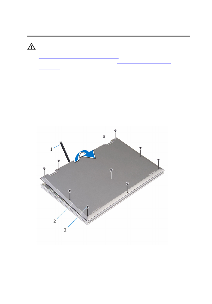
1 Close the display and turn the computer over.
2 Remove the screws that secure the base cover to the computer base.
3 Using a plastic scribe, pry the base cover away from the computer base.
14
1 plastic scribe 2 base cover
3 screws (10)
Page 15

Replacing the base cover
WARNING: Before working inside your computer, read the safety
information that shipped with your computer and follow the steps in
Before working inside your computer. After working inside your
computer, follow the instructions in After working inside your
computer. For more safety best practices, see the Regulatory
Compliance home page at www.dell.com/regulatory_compliance.
Procedure
1 Slide the tabs on the base cover into the slots on the computer base and
snap the base cover into place.
2 Replace the screws that secure the base cover to the computer base.
15
Page 16
Removing the battery
WARNING: Before working inside your computer, read the safety
information that shipped with your computer and follow the steps in
Before working inside your computer. After working inside your
computer, follow the instructions in After working inside your
computer. For more safety best practices, see the Regulatory
Compliance home page at www.dell.com/regulatory_compliance.
Prerequisites
Remove the base cover.
Procedure
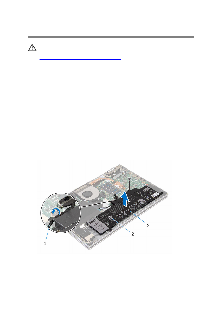
1 Remove the screws that secure the battery to the palmrest and keyboard
assembly.
2 Remove the hard-drive cable from the routing guides on the battery.
3 Lift the battery off the palmrest and keyboard assembly.
16
1 hard-drive cable 2 screws (2)
3 battery
Page 17

4 Turn the computer over.
5 Press and hold the power button for 5 seconds, to ground the system
board.
17
Page 18

Replacing the battery
WARNING: Before working inside your computer, read the safety
information that shipped with your computer and follow the steps in
Before working inside your computer. After working inside your
computer, follow the instructions in After working inside your
computer. For more safety best practices, see the Regulatory
Compliance home page at www.dell.com/regulatory_compliance.
Procedure
1 Align the screw holes on the battery with the screw holes on the palmrest
and keyboard assembly and place the battery on the palmrest and
keyboard assembly.
2 Route the hard-drive cable through the routing guides on the battery.
3 Replace the screws that secure the battery to the palmrest and keyboard
assembly.
Post-requisites
Replace the base cover.
18
Page 19

Removing the memory module
WARNING: Before working inside your computer, read the safety
information that shipped with your computer and follow the steps in
Before working inside your computer. After working inside your
computer, follow the instructions in After working inside your
computer. For more safety best practices, see the Regulatory
Compliance home page at www.dell.com/regulatory_compliance.
Prerequisites
1 Remove the base cover.
2 Remove the battery.
Procedure
1 Use your fingertips to carefully spread apart the securing-clips on each
end of the memory-module slot until the memory module pops up.
19
Page 20
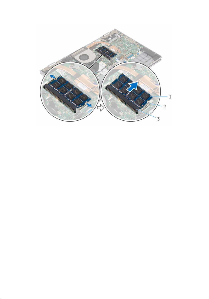
2 Remove the memory module from the memory-module slot.
1 memory module 2 securing clips (2)
3 memory-module slot
20
Page 21

Replacing the memory module
WARNING: Before working inside your computer, read the safety
information that shipped with your computer and follow the steps in
Before working inside your computer. After working inside your
computer, follow the instructions in After working inside your
computer. For more safety best practices, see the Regulatory
Compliance home page at www.dell.com/regulatory_compliance.
Procedure
1 Align the notch on the memory module with the tab on the memory-
module slot.
21
Page 22
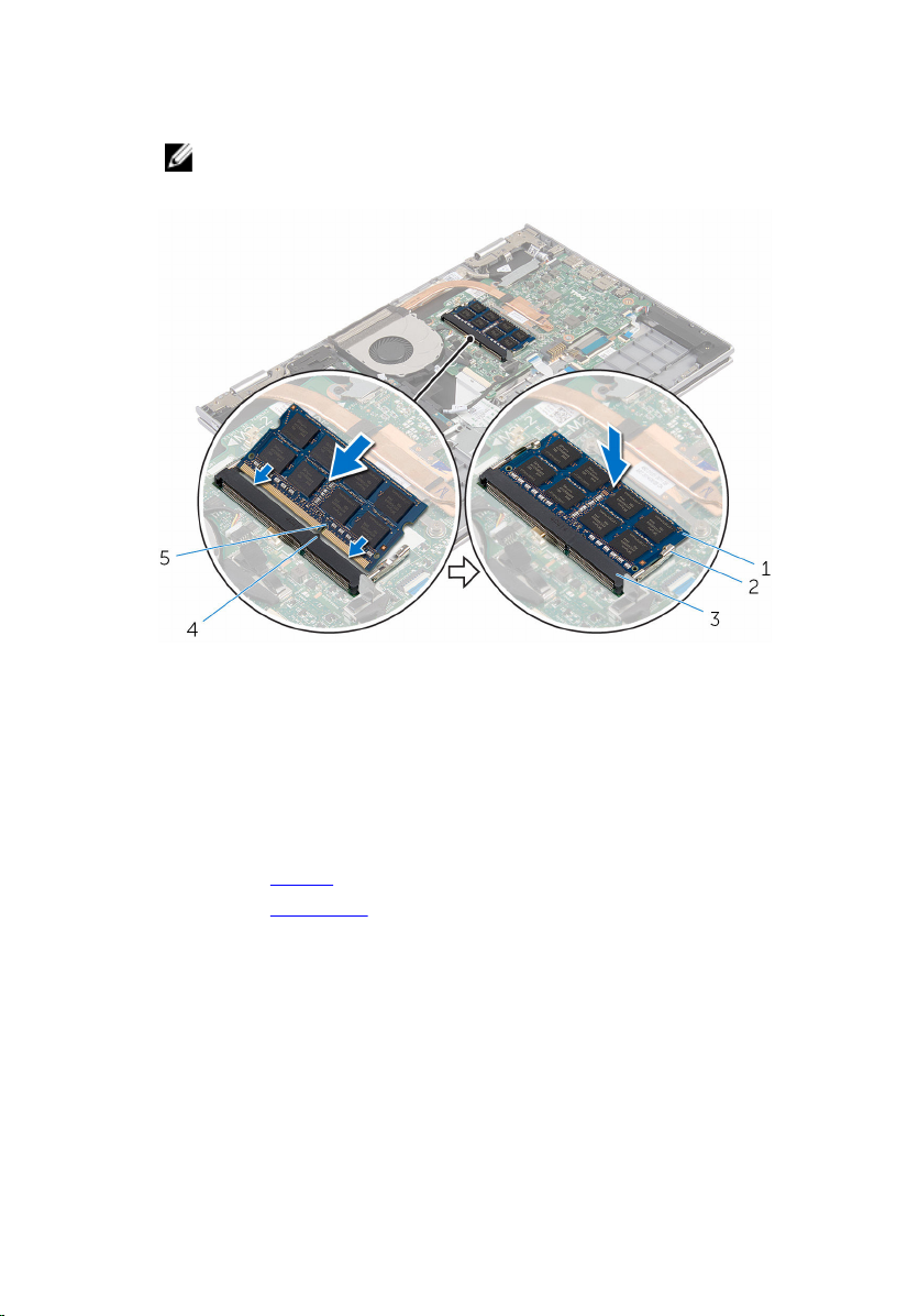
2 Slide the memory module firmly into the slot at an angle and press the
memory module down until it clicks into place.
NOTE: If you do not hear the click, remove the memory module
and reinstall it.
1 memory module 2 securing clips (2)
3 memory-module slot 4 tab
5 notch
Post-requisites
1 Replace the battery.
2 Replace the base cover.
22
Page 23

Removing the hard drive
WARNING: Before working inside your computer, read the safety
information that shipped with your computer and follow the steps in
Before working inside your computer. After working inside your
computer, follow the instructions in After working inside your
computer. For more safety best practices, see the Regulatory
Compliance home page at www.dell.com/regulatory_compliance.
CAUTION: Hard drives are fragile. Exercise care when handling the
hard drive.
CAUTION: To avoid data loss, do not remove the hard drive while the
computer is in sleep or on state.
Prerequisites
1 Remove the base cover.
2 Remove the battery.
Procedure
1 Remove the screws that secure the hard-drive assembly to the palmrest
and keyboard assembly.
2 Using the pull tab, disconnect the hard-drive cable from the system
board.
23
Page 24
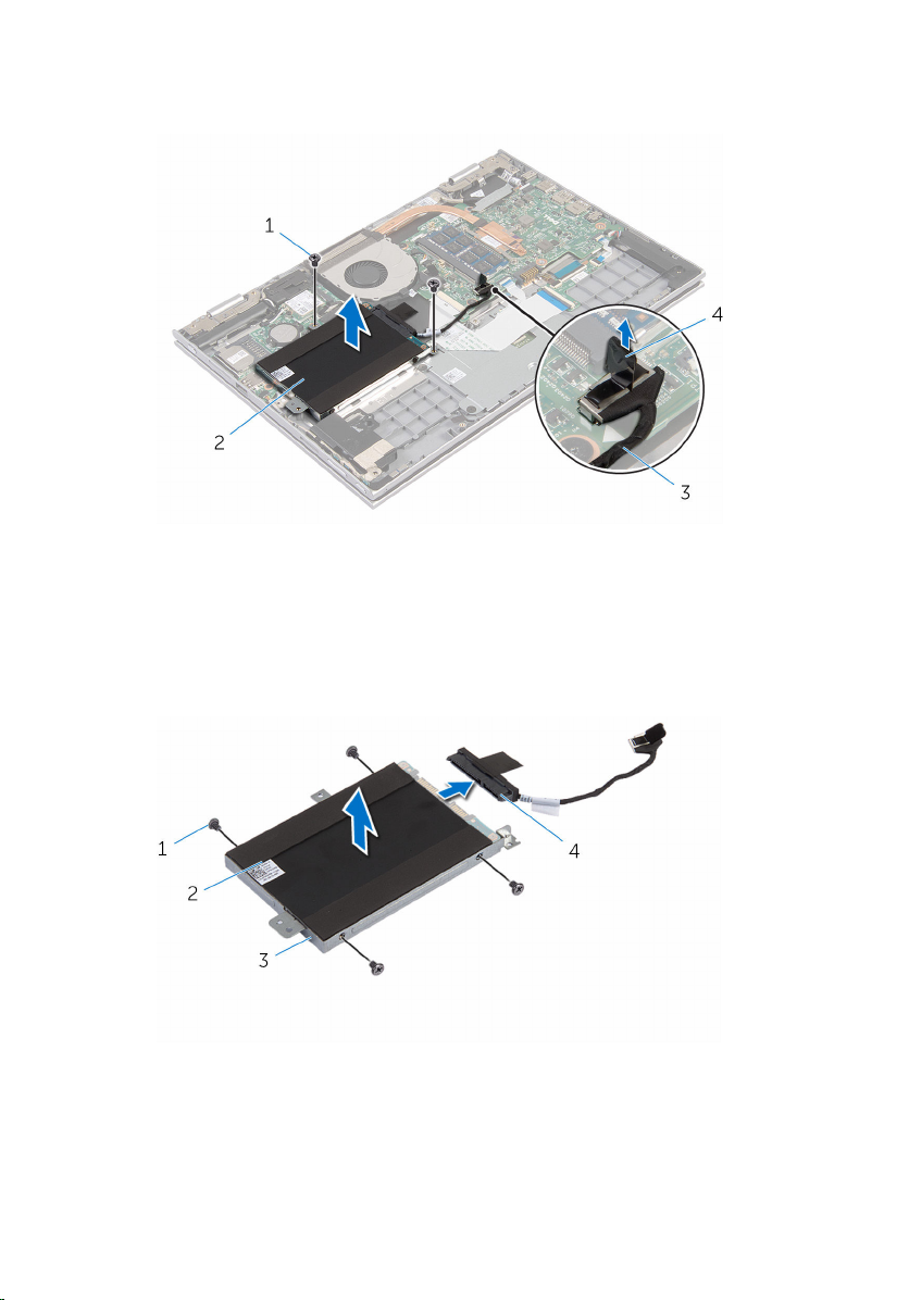
3 Lift the hard-drive assembly along with its cable off the palmrest and
keyboard assembly.
1 screws (2) 2 hard-drive assembly
3 hard-drive cable 4 pull tab
4 Disconnect the interposer from the hard drive.
5 Remove the screws that secure the hard-drive bracket to the hard drive.
6 Lift the hard-drive bracket from the hard drive.
24
1 screws (4) 2 hard drive
3 hard-drive bracket 4 interposer
Page 25

Replacing the hard drive
WARNING: Before working inside your computer, read the safety
information that shipped with your computer and follow the steps in
Before working inside your computer. After working inside your
computer, follow the instructions in After working inside your
computer. For more safety best practices, see the Regulatory
Compliance home page at www.dell.com/regulatory_compliance.
CAUTION: Hard drives are fragile. Exercise care when handling the
hard drive.
Procedure
1 Align the screw holes on the hard drive with the screw holes on the hard-
drive bracket.
2 Replace the screws that secure the hard-drive bracket to the hard drive.
3 Connect the interposer to the hard-drive assembly.
4 Align the screw holes on the hard-drive assembly with the screw holes
on the palmrest and keyboard assembly.
5 Replace the screws that secure the hard-drive assembly to the palmrest
and keyboard assembly.
6 Connect the hard-drive cable to the system board.
Post-requisites
1 Replace the battery.
2 Replace the base cover.
25
Page 26

Removing the coin-cell battery
WARNING: Before working inside your computer, read the safety
information that shipped with your computer and follow the steps in
Before working inside your computer. After working inside your
computer, follow the instructions in After working inside your
computer. For more safety best practices, see the Regulatory
Compliance home page at www.dell.com/regulatory_compliance.
CAUTION: Removing the coin-cell battery resets the BIOS setup
program’s settings to default. It is recommended that you note the
BIOS setup program’s settings before removing the coin-cell battery.
Prerequisites
1 Remove the base cover.
2 Remove the battery.
Procedure
Using a plastic scribe, gently pry the coin-cell battery out of the battery
socket on the I/O board.
26
Page 27
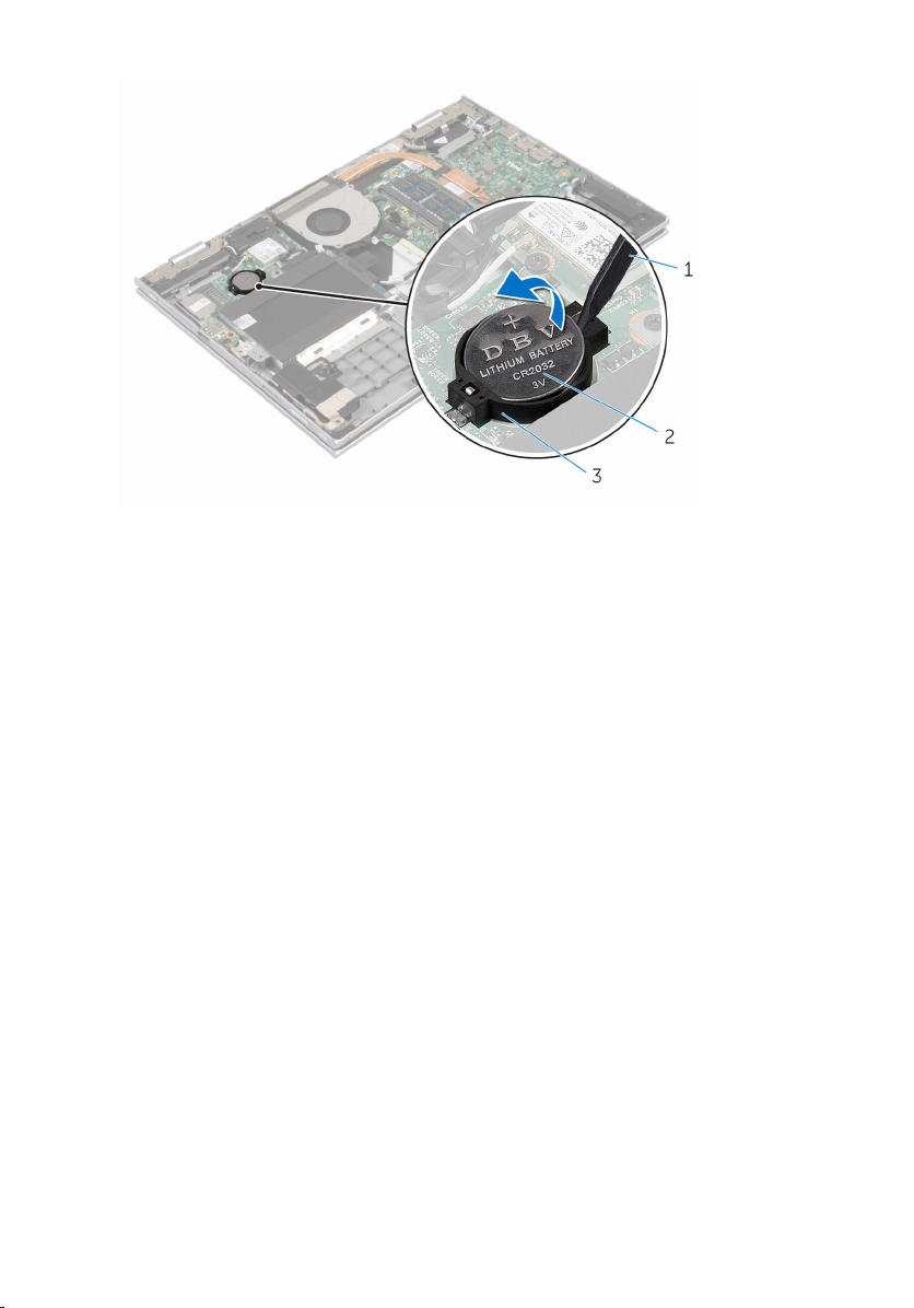
1 plastic scribe 2 coin-cell battery
3 battery socket
27
Page 28

Replacing the coin-cell battery
WARNING: Before working inside your computer, read the safety
information that shipped with your computer and follow the steps in
Before working inside your computer. After working inside your
computer, follow the instructions in After working inside your
computer. For more safety best practices, see the Regulatory
Compliance home page at www.dell.com/regulatory_compliance.
Procedure
With the positive-side facing up, snap the coin-cell battery into the battery
socket on the I/O board.
Post-requisites
1 Replace the battery.
2 Replace the base cover.
28
Page 29

Removing the wireless card
WARNING: Before working inside your computer, read the safety
information that shipped with your computer and follow the steps in
Before working inside your computer. After working inside your
computer, follow the instructions in After working inside your
computer. For more safety best practices, see the Regulatory
Compliance home page at www.dell.com/regulatory_compliance.
Prerequisites
1 Remove the base cover.
2 Remove the battery.
Procedure
1 Disconnect the antenna cables from the wireless card.
2 Remove the screw that secures the wireless card to the I/O board.
29
Page 30
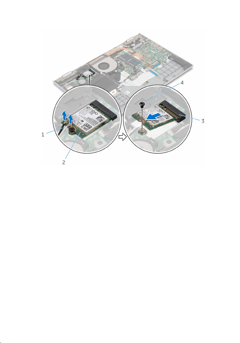
3 Slide and remove the wireless card from the wireless-card slot.
1 antenna cables (2) 2 wireless card
3 wireless-card slot 4 screw
30
Page 31
Replacing the wireless card
WARNING: Before working inside your computer, read the safety
information that shipped with your computer and follow the steps in
Before working inside your computer. After working inside your
computer, follow the instructions in After working inside your
computer. For more safety best practices, see the Regulatory
Compliance home page at www.dell.com/regulatory_compliance.
Procedure
CAUTION: To avoid damage to the wireless card, do not place any
cables under it.
1 Align the notch on the wireless card with the tab on the wireless-card
slot on the I/O board.
2 Insert the wireless card at an angle into the wireless-card slot.
3 Align the screw hole on the wireless card with the screw hole on the I/O
board.
4 Replace the screw that secures the wireless card to the I/O board.
5 Connect the antenna cables to the wireless card.
The following table provides the antenna-cable color scheme for the
wireless card supported by your computer.
Connectors on the wireless card Antenna-cable color
Main (white triangle) white
Auxiliary (black triangle) black
Post-requisites
1 Replace the battery.
2 Replace the base cover.
31
Page 32

Removing the keyboard daughter-board
WARNING: Before working inside your computer, read the safety
information that shipped with your computer and follow the steps in
Before working inside your computer. After working inside your
computer, follow the instructions in After working inside your
computer. For more safety best practices, see the Regulatory
Compliance home page at www.dell.com/regulatory_compliance.
Prerequisites
1 Remove the base cover.
2 Remove the battery.
Procedure
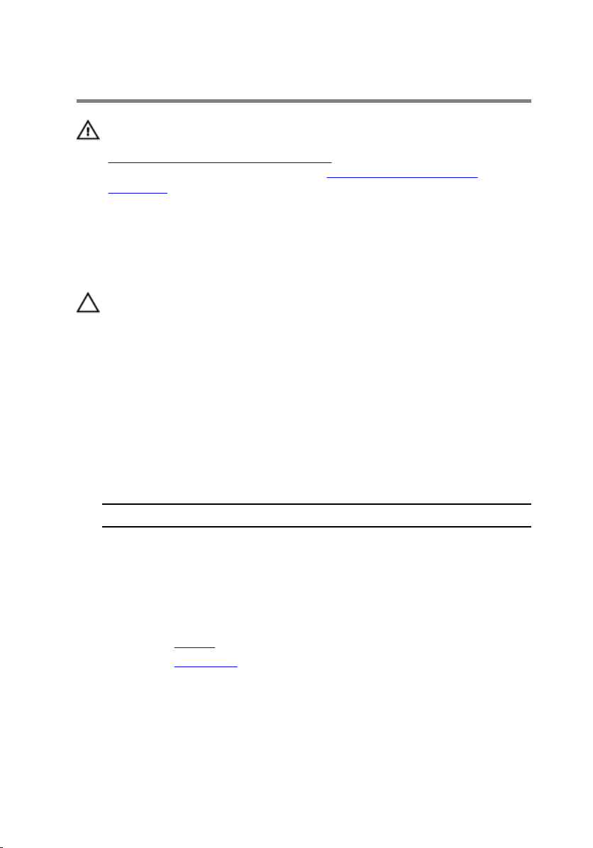
1 Lift the connector latches and disconnect the keyboard cables and
keyboard-backlight cables from the keyboard daughter-board.
32
Page 33
2 Lift the keyboard daughter-board off the palmrest and keyboard
assembly.
1 keyboard cable 2 keyboard-backlight cable
3 keyboard cable 4 keyboard-backlight cable
5 keyboard daughter-board
33
Page 34

Replacing the keyboard daughter-board
WARNING: Before working inside your computer, read the safety
information that shipped with your computer and follow the steps in
Before working inside your computer. After working inside your
computer, follow the instructions in After working inside your
computer. For more safety best practices, see the Regulatory
Compliance home page at www.dell.com/regulatory_compliance.
Procedure
1 Place the keyboard daughter board on the palmrest and keyboard
assembly.
2 Connect the keyboard cables and keyboard-backlight cables and press
down the latches to secure the cables.
Post-requisites
1 Replace the battery.
2 Replace the base cover.
34
Page 35

Removing the power and volume-buttons board
WARNING: Before working inside your computer, read the safety
information that shipped with your computer and follow the steps in
Before working inside your computer. After working inside your
computer, follow the instructions in After working inside your
computer. For more safety best practices, see the Regulatory
Compliance home page at www.dell.com/regulatory_compliance.
Prerequisites
1 Remove the base cover.
2 Remove the battery.
3 Follow the procedure from step 1 to step 3 in “Removing the hard drive”.
Procedure
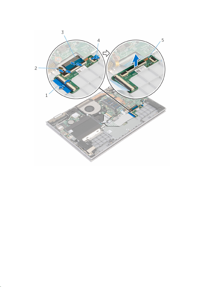
1 Peel off the adhesive tape that secures the power and volume-buttons
board cable to the palmrest and keyboard assembly.
2 Disconnect the power and volume-buttons board cable from the I/O
board.
3 Remove the power and volume-buttons board cable from the routing
guides on the speaker.
4 Peel off adhesive the tape that secures the power and volume-buttons
board to the speaker.
35
Page 36
5 Lift the power and volume-buttons board along with its cable, off the
palmrest and keyboard assembly.
1 adhesive tape 2 power and volume-
buttons board cable
36
3 power and volume-buttons
board
4 adhesive tape
Page 37

Replacing the power and volume-buttons board
WARNING: Before working inside your computer, read the safety
information that shipped with your computer and follow the steps in
Before working inside your computer. After working inside your
computer, follow the instructions in After working inside your
computer. For more safety best practices, see the Regulatory
Compliance home page at www.dell.com/regulatory_compliance.
Procedure
1 Place the power and volume-buttons board into the slot on the palmrest
and keyboard assembly.
2 Adhere the adhesive tape that secures the power and volume-buttons
board to the speaker.
3 Route the power and volume-buttons board cable through the routing
guides on the speaker.
4 Connect the power and volume-buttons board cable to the I/O board.
5 Adhere the adhesive tape that secures the power and volume-buttons
board cable to the palmrest and keyboard assembly.
Post-requisites
1 Follow the procedure from step 4 to step 6 in “Replacing the hard drive”.
2 Replace the battery.
3 Replace the base cover.
37
Page 38

Removing the speakers
WARNING: Before working inside your computer, read the safety
information that shipped with your computer and follow the steps in
Before working inside your computer. After working inside your
computer, follow the instructions in After working inside your
computer. For more safety best practices, see the Regulatory
Compliance home page at www.dell.com/regulatory_compliance.
Prerequisites
1 Remove the base cover.
2 Remove the battery.
3 Remove the power and volume-buttons board.
Procedure
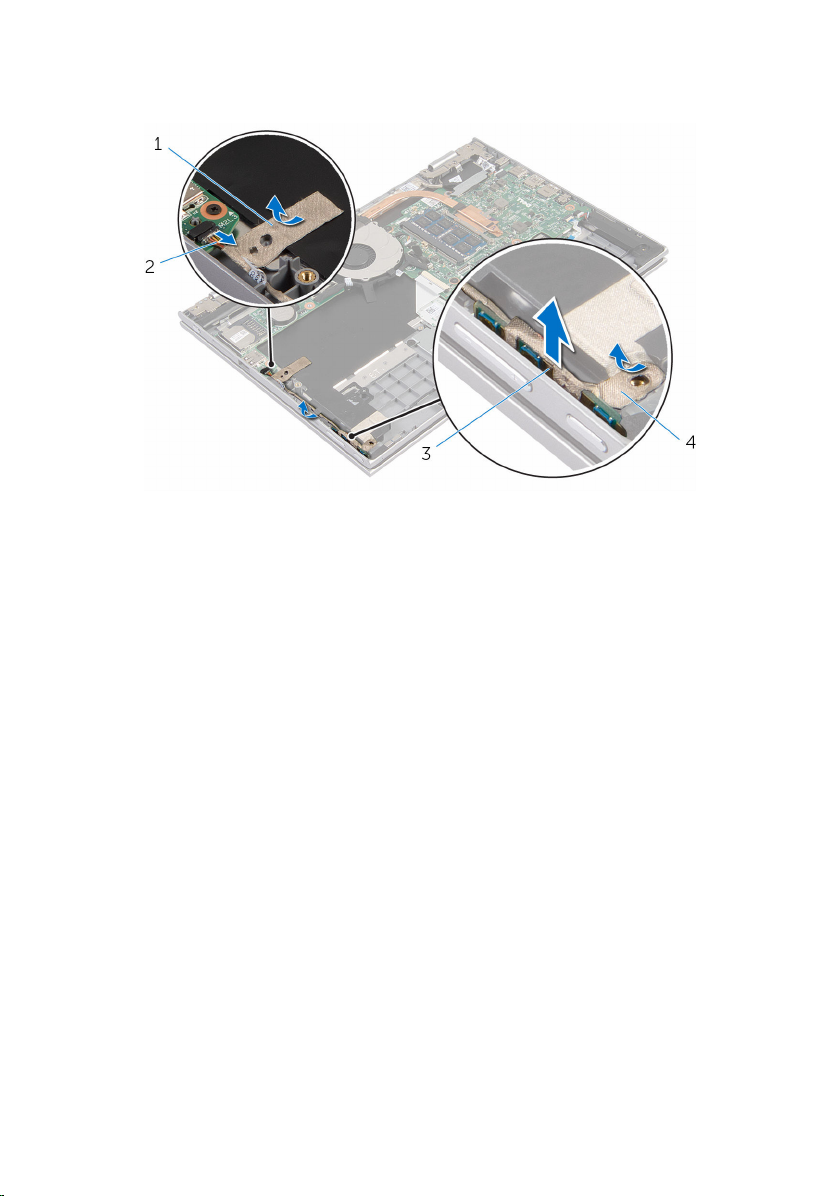
1 Disconnect the speaker cable from the system board.
2 Peel off the adhesive tape that secures the speaker cable to the palmrest
and keyboard assembly.
3 Remove the speaker cable from the routing guides on the palmrest and
keyboard assembly.
38
Page 39
4 Release the speakers from the alignment posts and lift the speakers along
with its cable off the palmrest and keyboard assembly.
1 speaker cable 2 speakers (2)
3 routing guides 4 adhesive tape
39
Page 40

Replacing the speakers
WARNING: Before working inside your computer, read the safety
information that shipped with your computer and follow the steps in
Before working inside your computer. After working inside your
computer, follow the instructions in After working inside your
computer. For more safety best practices, see the Regulatory
Compliance home page at www.dell.com/regulatory_compliance.
Procedure
1 Using the alignment posts on the palmrest and keyboard assembly, place
the speakers on the palmrest and keyboard assembly.
2 Route the speaker cable through the routing guides on the palmrest and
keyboard assembly.
3 Adhere the adhesive tapes that secure the speaker cable on the palmrest
and keyboard assembly.
4 Connect the speaker cable to the system board.
Post-requisites
1 Replace the power and volume-buttons board.
2 Replace the battery.
3 Replace the base cover.
40
Page 41
Removing the touch pad
WARNING: Before working inside your computer, read the safety
information that shipped with your computer and follow the steps in
Before working inside your computer. After working inside your
computer, follow the instructions in After working inside your
computer. For more safety best practices, see the Regulatory
Compliance home page at www.dell.com/regulatory_compliance.
Prerequisites
1 Remove the base cover.
2 Remove the battery.
Procedure
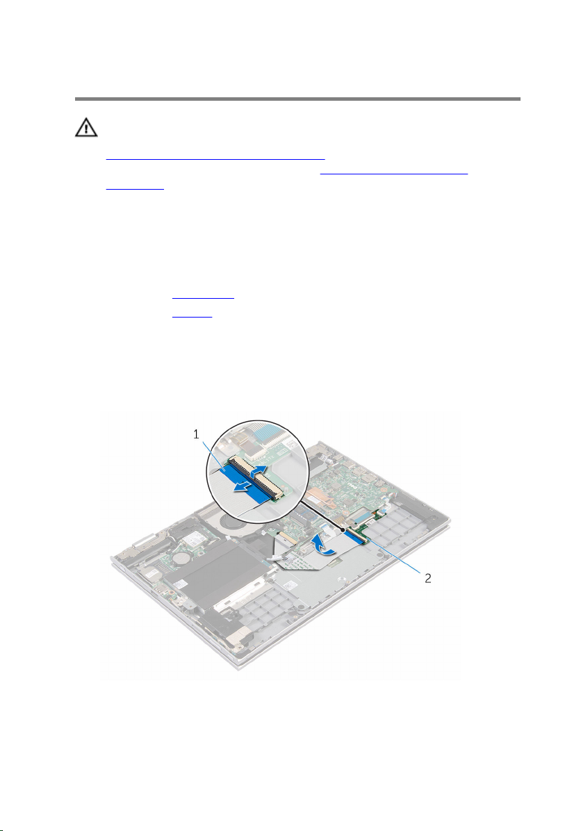
1 Lift the connector latch and disconnect the keyboard cable from the
keyboard daughter-board.
1 keyboard cable 2 keyboard daughter-board
41
Page 42
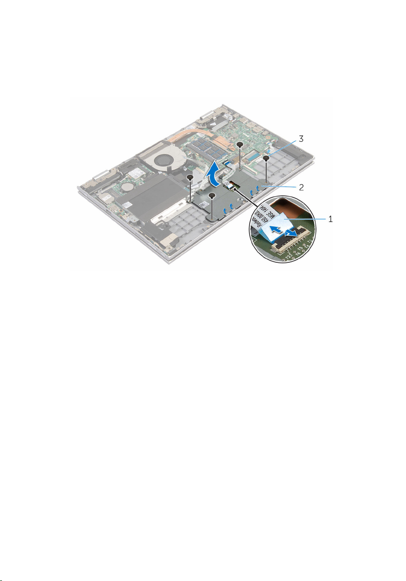
2 Lift the connector latch and disconnect the touch-pad cable from the
touch pad.
3 Remove the screws that secure the touch-pad bracket to the palmrest
and keyboard assembly.
4 Lift the touch-pad bracket off the palmrest and keyboard assembly.
1 touch-pad cable 2 touch-pad bracket
3 screws (4)
5 Peel off the adhesive tape that secures the touch pad to the palmrest and
keyboard assembly.
42
Page 43
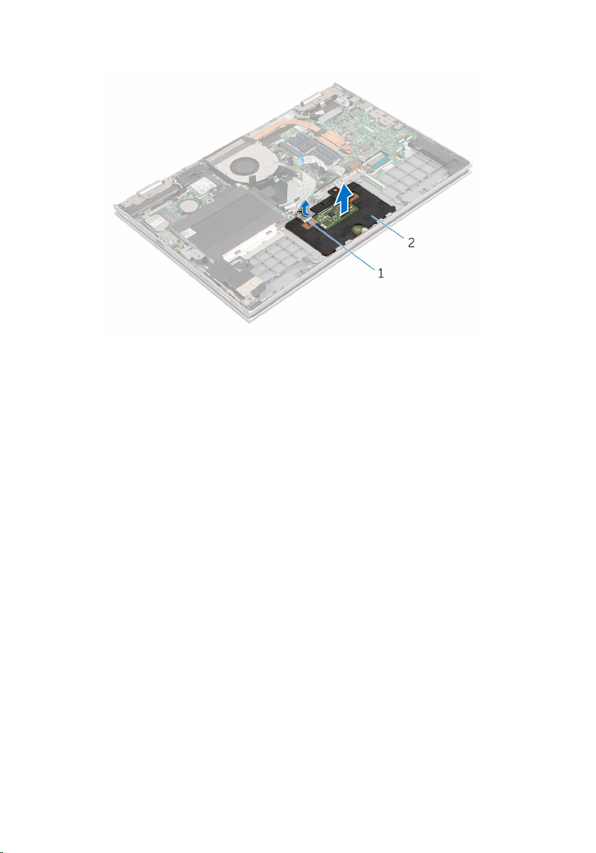
6 Lift the touch pad away from the computer.
1 adhesive tape 2 touch pad
43
Page 44

Replacing the touch pad
WARNING: Before working inside your computer, read the safety
information that shipped with your computer and follow the steps in
Before working inside your computer. After working inside your
computer, follow the instructions in After working inside your
computer. For more safety best practices, see the Regulatory
Compliance home page at www.dell.com/regulatory_compliance.
Procedure
1 Slide the tabs on the touch pad into the slots on the palmrest and
keyboard assembly.
2 Adhere the adhesive tape that secures the touch pad to the palmrest and
keyboard assembly.
3 Align the screw holes on the touch-pad bracket with the screw holes on
the palmrest and keyboard assembly.
4 Replace the screws that secure the touch-pad bracket to the palmrest
and keyboard assembly.
5 Slide the touch-pad cable into the touch-pad connector and press down
the latch to secure the cable.
6 Slide the keyboard cable into the keyboard daughter-board connector
and press down the latch to secure the cable.
Post-requisites
1 Replace the battery.
2 Replace the base cover.
44
Page 45
Removing the fan
WARNING: Before working inside your computer, read the safety
information that shipped with your computer and follow the steps in
Before working inside your computer. After working inside your
computer, follow the instructions in After working inside your
computer. For more safety best practices, see the Regulatory
Compliance home page at www.dell.com/regulatory_compliance.
Prerequisites
1 Remove the base cover.
2 Remove the battery.
Procedure
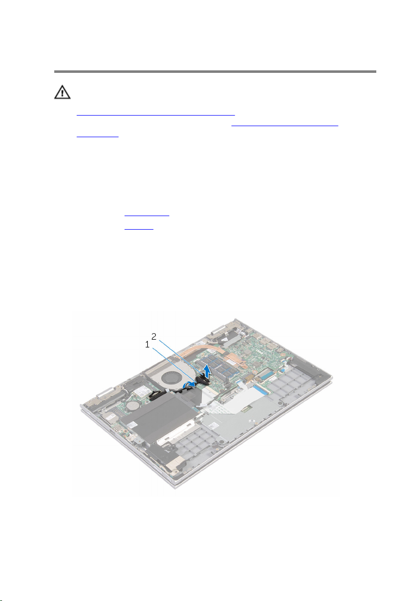
1 Using the pull tab, disconnect the I/O-board cable from the system
board.
2 Remove the I/O-board cable from the routing guides on the fan.
1 I/O-board cable 2 I/O-board cable
connector
45
Page 46
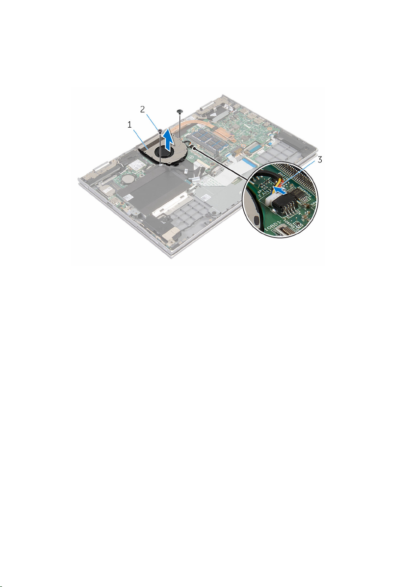
3 Disconnect the fan cable from the system board.
4 Remove the screws that secure the fan to the palmrest and keyboard
assembly.
5 Lift the fan off the palmrest and keyboard assembly.
1 fan 2 screws (2)
3 fan cable
46
Page 47

Replacing the fan
WARNING: Before working inside your computer, read the safety
information that shipped with your computer and follow the steps in
Before working inside your computer. After working inside your
computer, follow the instructions in After working inside your
computer. For more safety best practices, see the Regulatory
Compliance home page at www.dell.com/regulatory_compliance.
Procedure
1 Align the screw holes on the fan with the screw holes on the palmrest
and keyboard assembly.
2 Replace the screws that secure the fan to the palmrest and keyboard
assembly.
3 Connect the fan cable to the system board.
4 Route the I/O-board cable through the routing guides on the fan.
5 Slide the I/O-board cable into the I/O-board cable connector on the
system board and press down the latch to secure the cable.
Post-requisites
1 Replace the battery.
2 Replace the base cover.
47
Page 48

Removing the heat sink
WARNING: Before working inside your computer, read the safety
information that shipped with your computer and follow the steps in
Before working inside your computer. After working inside your
computer, follow the instructions in After working inside your
computer. For more safety best practices, see the Regulatory
Compliance home page at www.dell.com/regulatory_compliance.
WARNING: The heat sink may become hot during normal operation.
Allow sufficient time for the heat sink to cool before you touch it.
CAUTION: For maximum cooling of the processor, do not touch the
heat transfer areas on the heat sink. The oils in your skin can reduce
the heat transfer capability of the thermal grease.
Prerequisites
1 Remove the base cover.
2 Remove the battery.
Procedure
1 In sequential order (as indicated on the heat sink), loosen the captive
screws that secure the heat sink to the system board.
48
Page 49
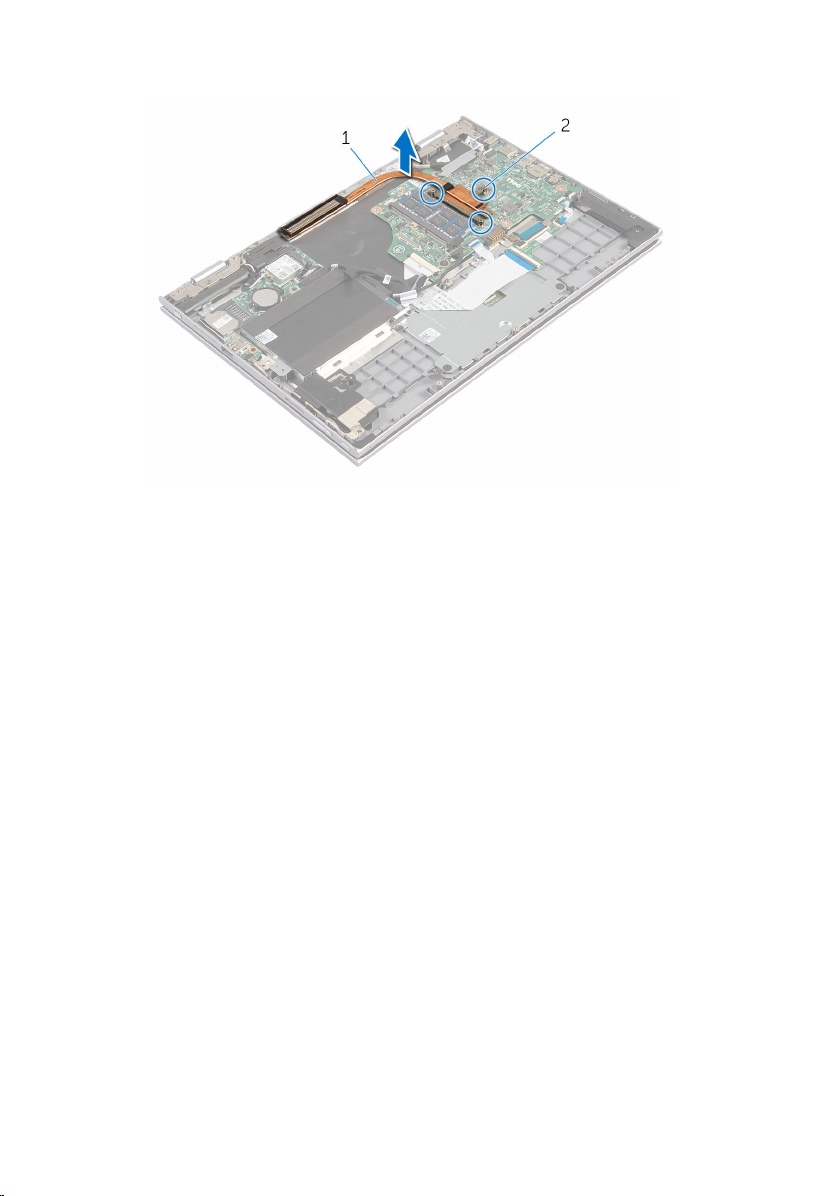
2 Lift the heat sink off the system board.
1 heat sink 2 captive screws (3)
49
Page 50

Replacing the heat sink
WARNING: Before working inside your computer, read the safety
information that shipped with your computer and follow the steps in
Before working inside your computer. After working inside your
computer, follow the instructions in After working inside your
computer. For more safety best practices, see the Regulatory
Compliance home page at www.dell.com/regulatory_compliance.
CAUTION: Incorrect alignment of the heat sink can cause damage to
the system board and processor.
NOTE: The original thermal grease can be reused if the original system
board and heat sink are reinstalled together. If either the system board
or the heat sink is replaced, use the thermal pad provided in the kit to
ensure that thermal conductivity is achieved.
Procedure
1 Align the screw holes on the heat sink with the screw holes on the
system board.
2 In sequential order (indicated on the heat sink), tighten the captive screws
that secure the heat sink to the system board.
Post-requisites
1 Replace the battery.
2 Replace the base cover.
50
Page 51

Removing the I/O board
WARNING: Before working inside your computer, read the safety
information that shipped with your computer and follow the steps in
Before working inside your computer. After working inside your
computer, follow the instructions in After working inside your
computer. For more safety best practices, see the Regulatory
Compliance home page at www.dell.com/regulatory_compliance.
Prerequisites
1 Remove the base cover.
2 Remove the battery.
3 Remove the hard drive.
4 Remove the wireless card.
5 Remove the coin-cell battery.
Procedure
1 Using the pull tab, disconnect the I/O-board cable from the I/O board.
2 Disconnect the power and volume-buttons board cable from the I/O
board.
3 Remove the screw that secures the I/O board to the palmrest and
keyboard assembly.
51
Page 52
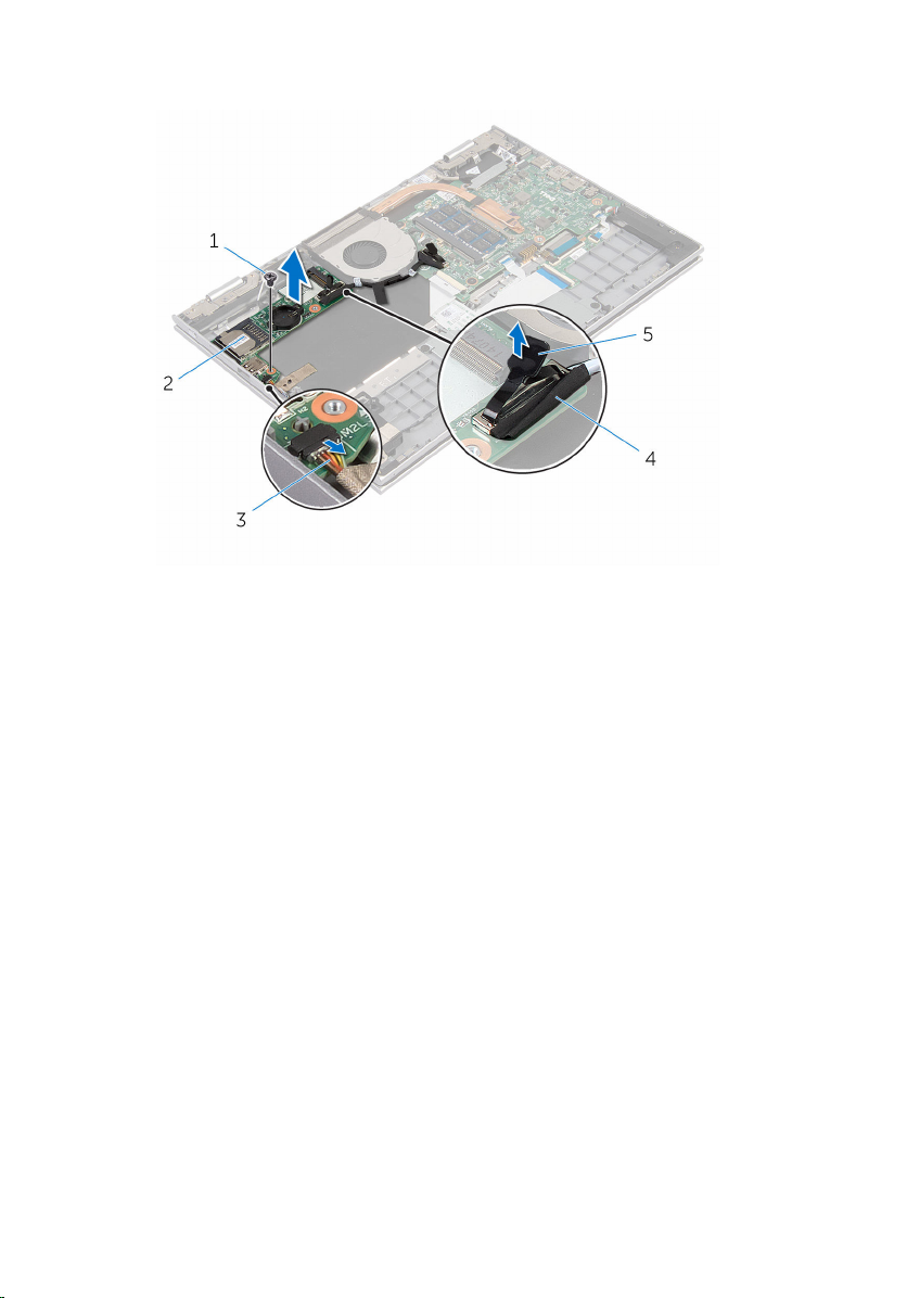
4 Lift the I/O board off the palmrest and keyboard assembly.
1 screw 2 I/O-board
52
3 power and volume-buttons
board cable
5 pull tab
4 I/O-board cable
Page 53

Replacing the I/O board
WARNING: Before working inside your computer, read the safety
information that shipped with your computer and follow the steps in
Before working inside your computer. After working inside your
computer, follow the instructions in After working inside your
computer. For more safety best practices, see the Regulatory
Compliance home page at www.dell.com/regulatory_compliance.
Procedure
1 Using the alignment posts, place the I/O board on the palmrest and
keyboard assembly.
2 Align the screw hole on the I/O board with the screw hole on the
palmrest and keyboard assembly.
3 Replace the screw that secures the I/O board to the palmrest and
keyboard assembly.
4 Connect the power and volume-buttons board cable to the I/O board.
5 Connect the I/O-board cable to the I/O board.
Post-requisites
1 Replace the coin-cell battery.
2 Replace the wireless card.
3 Replace the hard drive.
4 Replace the battery.
5 Replace the base cover.
53
Page 54

Removing the power-adapter port
WARNING: Before working inside your computer, read the safety
information that shipped with your computer and follow the steps in
Before working inside your computer. After working inside your
computer, follow the instructions in After working inside your
computer. For more safety best practices, see the Regulatory
Compliance home page at www.dell.com/regulatory_compliance.
Prerequisites
1 Remove the base cover.
2 Remove the battery.
Procedure
1 Disconnect the power-adapter port cable from the system board.
2 Remove the screw that secures the power-adapter port to the palmrest
and keyboard assembly.
54
Page 55
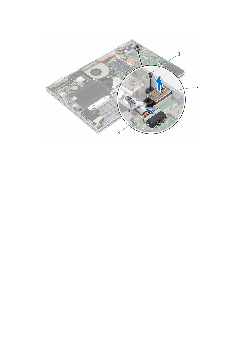
3 Lift the power-adapter port with its cable, off the palmrest and keyboard
assembly.
1 screw 2 power-adapter port
3 power-adapter port cable
55
Page 56

Replacing the power-adapter port
WARNING: Before working inside your computer, read the safety
information that shipped with your computer and follow the steps in
Before working inside your computer. After working inside your
computer, follow the instructions in After working inside your
computer. For more safety best practices, see the Regulatory
Compliance home page at www.dell.com/regulatory_compliance.
Procedure
1 Place the power-adapter port into the slot on the palmrest and keyboard
assembly.
2 Align the screw hole on the power-adapter port with the screw hole on
the palmrest and keyboard assembly.
3 Connect the power-adapter port cable to the system board.
Post-requisites
1 Replace the battery.
2 Replace the base cover.
56
Page 57

Removing the system board
WARNING: Before working inside your computer, read the safety
information that shipped with your computer and follow the steps in
Before working inside your computer. After working inside your
computer, follow the instructions in After working inside your
computer. For more safety best practices, see the Regulatory
Compliance home page at www.dell.com/regulatory_compliance.
NOTE: Your computer’s Service Tag is stored in the system board. You
must enter the Service Tag in the BIOS setup program after you replace
the system board.
NOTE: Replacing the system board removes any changes you have
made to the BIOS using the BIOS setup program. You must make the
desired changes again after you replace the system board.
NOTE: Before disconnecting the cables from the system board, note the
location of the connectors so that you can reconnect the cables
correctly after you replace the system board.
Prerequisites
1 Remove the base cover.
2 Remove the battery.
3 Remove the memory module.
4 Remove the fan.
5 Remove the heat sink.
Procedure
1 Remove the screws that secure the display-cable bracket to the system
board and lift the display-cable bracket off the system board.
2 Using the pull tab disconnect the display cable from the system board.
57
Page 58
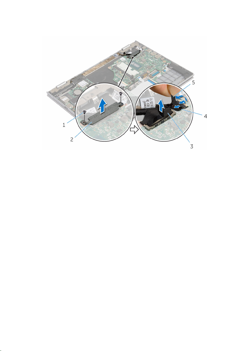
3 Peel off the adhesive tape on the Windows-button board connector and
disconnect the Windows-button board cable from the system board.
1 screws (2) 2 display-cable bracket
3 display cable 4 windows-button board
cable
5 adhesive tape
4 Using the pull tab disconnect the hard-drive cable from the system
board.
5 Release the latches and disconnect the keyboard cable from the system
board.
6 Open the latches and disconnect the keyboard-backlight cable and the
touch-pad cable from the system board.
58
Page 59
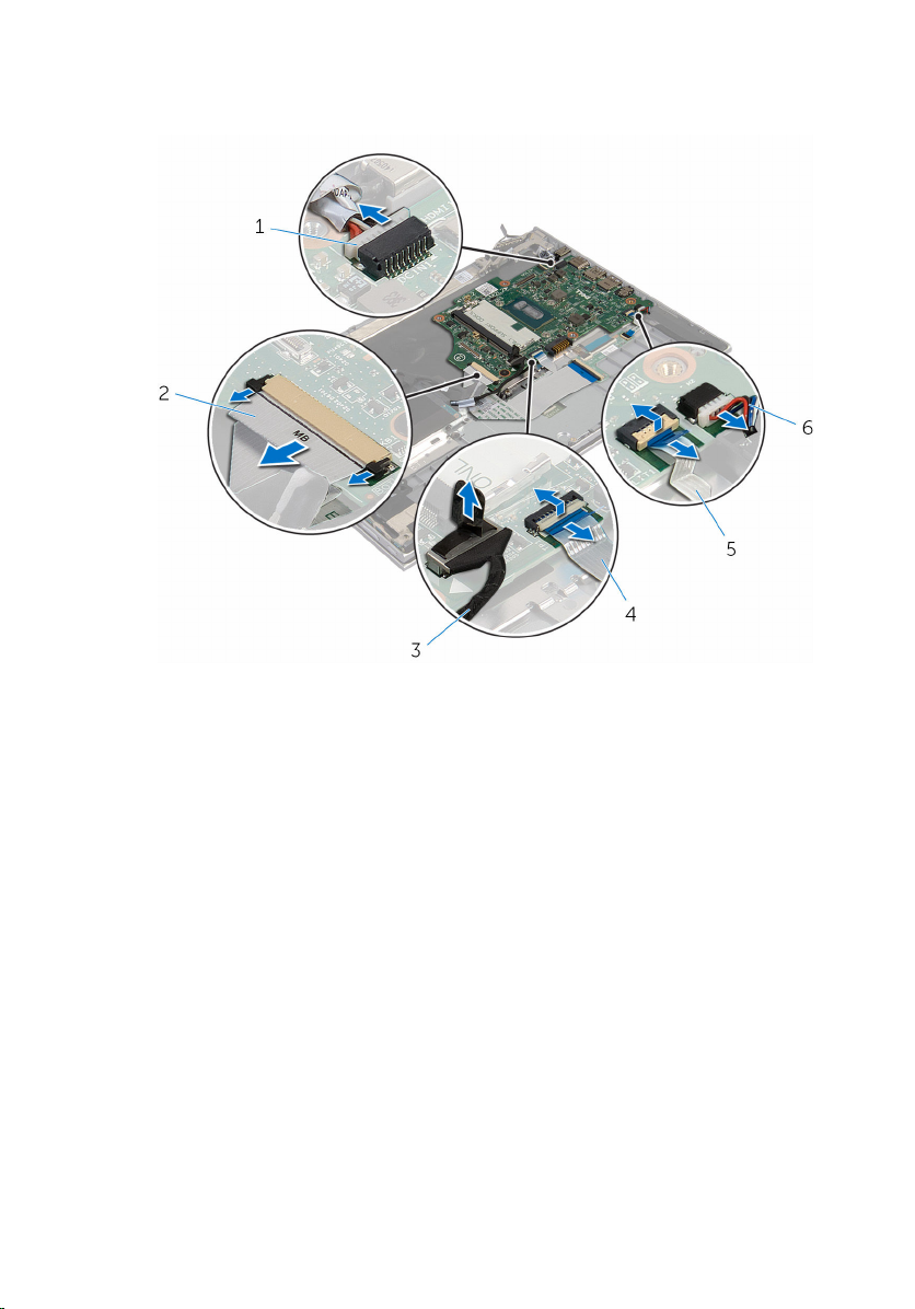
7 Disconnect the speaker cable and the power-adapter port cable from the
system board.
1 power-adapter port cable 2 keyboard cable
3 hard-drive cable 4 touch-pad cable
5 keyboard-backlight cable 6 speaker cable
8 Remove the screw that secures the system board to the palmrest and
keyboard assembly.
59
Page 60
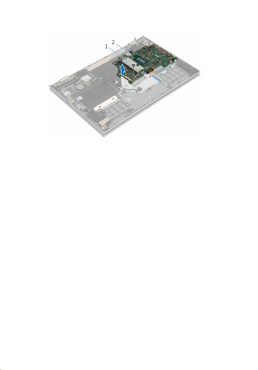
9 Lift the system board off the palmrest and keyboard assembly.
1 screw 2 system board
60
Page 61
Replacing the system board
WARNING: Before working inside your computer, read the safety
information that shipped with your computer and follow the steps in
Before working inside your computer. After working inside your
computer, follow the instructions in After working inside your
computer. For more safety best practices, see the Regulatory
Compliance home page at www.dell.com/regulatory_compliance.
NOTE: Your computer’s Service Tag is stored in the system board. You
must enter the Service Tag in the BIOS setup program after you replace
the system board.
NOTE: Replacing the system board removes any changes you have
made to the BIOS using the BIOS setup program. You must make the
desired changes again after you replace the system board.
Procedure
1 Align the screw hole on the system board with the screw hole on the
palmrest and keyboard assembly.
2 Replace the screw that secures the system board to the palmrest and
keyboard assembly.
3 Connect the power-adapter port cable and the speaker cable to the
system board.
4 Slide the touch-pad cable and the keyboard-backlight cable into their
connectors on the system board and close the latches to secure the
cables.
5 Slide the keyboard cable into the connector and push the latches to
secure the cable.
6 Connect the hard-drive cable to the system board.
7 Connect the Windows-button board cable to the connector on the
system board and adhere the tape on the Windows-button board
connector to secure the cable.
8 Connect the display cable to the system board.
9 Align the screw holes on the display-cable bracket with the screw holes
on the system board.
10 Replace the screws that secure the display-cable bracket to the system
board.
61
Page 62

Post-requisites
1 Replace the heat sink.
2 Replace the fan.
3 Replace the memory module.
4 Replace the battery.
5 Replace the base cover.
Entering the Service Tag in the BIOS setup program
1 Turn on the computer.
2 Press F2 when the DELL logo is displayed to enter the BIOS setup
program.
3 Navigate to the Main tab and enter the Service Tag in the Service Tag
Input field.
62
Page 63

Removing the display assembly
WARNING: Before working inside your computer, read the safety
information that shipped with your computer and follow the steps in
Before working inside your computer. After working inside your
computer, follow the instructions in After working inside your
computer. For more safety best practices, see the Regulatory
Compliance home page at www.dell.com/regulatory_compliance.
Prerequisites
1 Remove the base cover.
2 Remove the battery.
3 Remove the fan.
4 Remove the heat sink.
Procedure
1 Disconnect the antenna cables from the wireless card.
2 Remove the screws that secure the display-cable bracket to the system
board.
3 Lift the display-cable bracket off the system board.
4 Using the pull tab disconnect the display cable from the system board.
63
Page 64
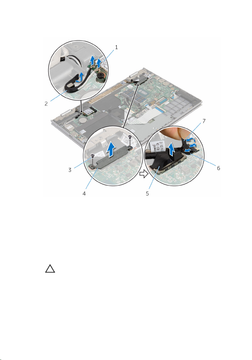
5 Peel off the adhesive tape on the Windows-button board connector and
disconnect it from the system board.
1 wireless card 2 antenna cables (2)
3 screws (2) 4 display-cable bracket
5 display cable 6 windows-button board
cable
7 adhesive tape
6 Turn the computer over and open the display as far as possible.
CAUTION: Place the computer on a soft and clean surface to avoid
scratching the display.
7 Place the computer face down on a flat surface.
8 Remove the screws that secure the display assembly to the palmrest and
keyboard assembly.
9 Peel off the adhesive tape that secures the display cable to the palmrest
and keyboard assembly.
64
Page 65
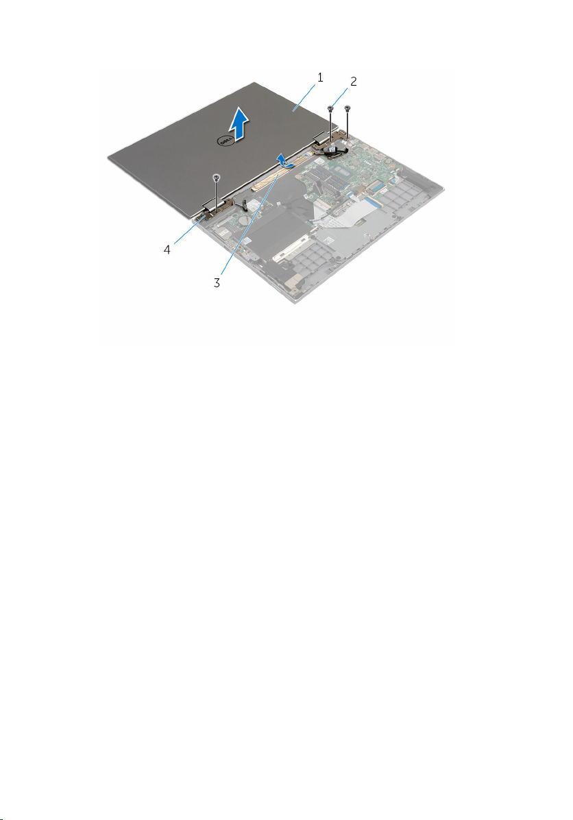
10 Lift the display assembly off the palmrest and keyboard assembly.
1 display assembly 2 screws (3)
3 adhesive tape 4 display hinges (2)
65
Page 66

Replacing the display assembly
WARNING: Before working inside your computer, read the safety
information that shipped with your computer and follow the steps in
Before working inside your computer. After working inside your
computer, follow the instructions in After working inside your
computer. For more safety best practices, see the Regulatory
Compliance home page at www.dell.com/regulatory_compliance.
Procedure
CAUTION: Place the computer on a soft and clean surface to avoid
scratching the display.
1 Place the display assembly on the palmrest and keyboard assembly.
2 Align the screw holes on the display hinges with the screw holes on the
palmrest and keyboard assembly.
3 Adhere the adhesive tape that secures the the display cable to the
palmrest and keyboard assembly.
4 Replace the screws that secure the display assembly to the palmrest and
keyboard assembly.
5 Turn the computer over and close the display.
6 Slide the Windows button-board connector into the connector latch on
the system board and press down the latch to secure the cable.
7 Adhere the tape to the Windows button-board cable.
8 Connect the display cable to the system board.
9 Align the screw holes on the display-cable bracket with the screw holes
on the system board.
10 Replace the screws that secure the display-cable bracket to the system
board.
11 Connect the antenna cables to the wireless card.
Post-requisites
1 Replace the battery.
2 Replace the base cover.
66
Page 67

Removing the stylus-holder assembly
WARNING: Before working inside your computer, read the safety
information that shipped with your computer and follow the steps in
Before working inside your computer. After working inside your
computer, follow the instructions in After working inside your
computer. For more safety best practices, see the Regulatory
Compliance home page at www.dell.com/regulatory_compliance.
Prerequisites
1 Remove the base cover.
2 Remove the battery.
3 Remove the display assembly.
67
Page 68
Procedure
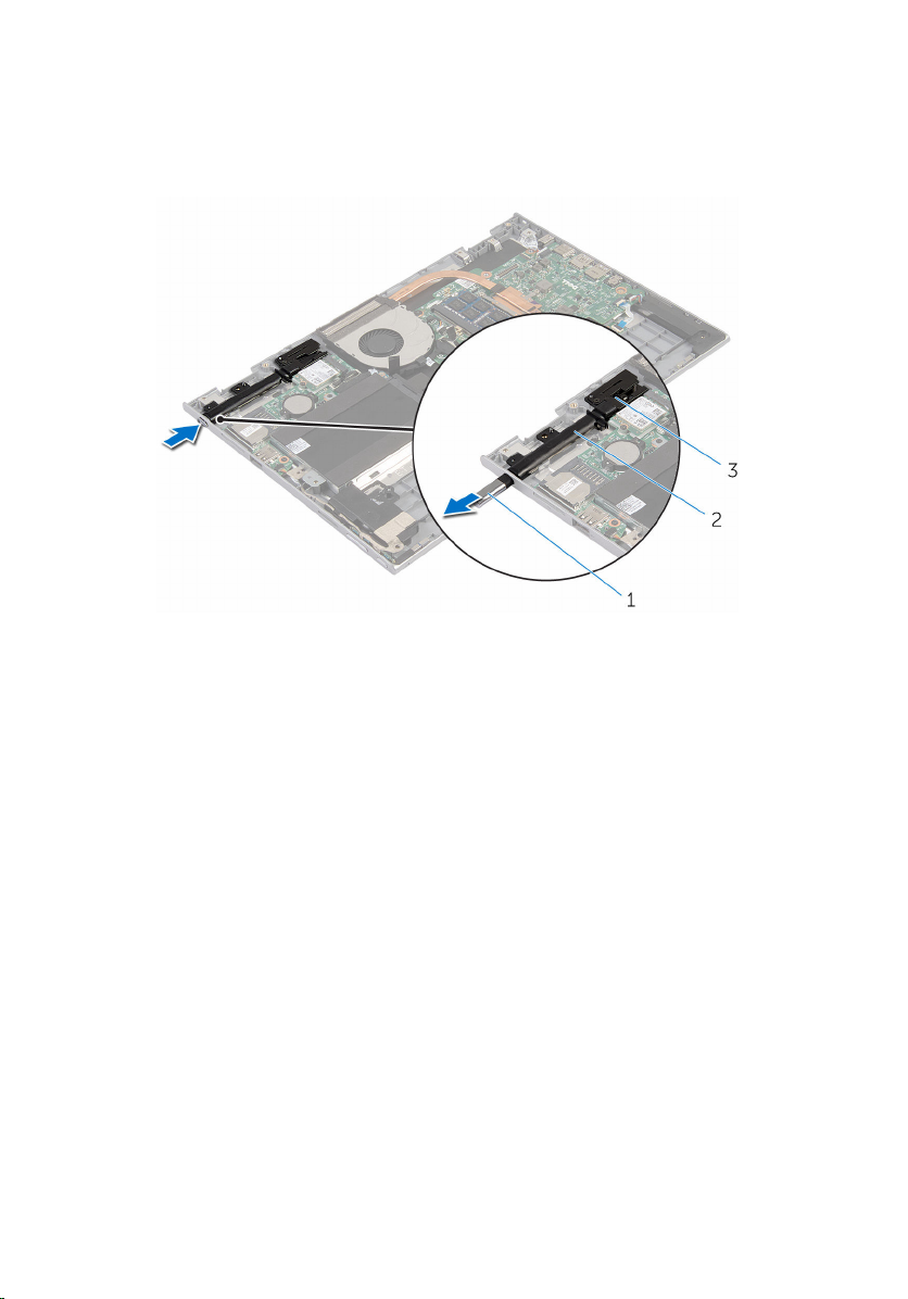
1 Push to release the stylus from the stylus holder.
1 stylus 2 stylus holder
3 stylus lock
2 Remove the screw and lift the stylus lock from the palmrest and keyboard
assembly.
68
Page 69
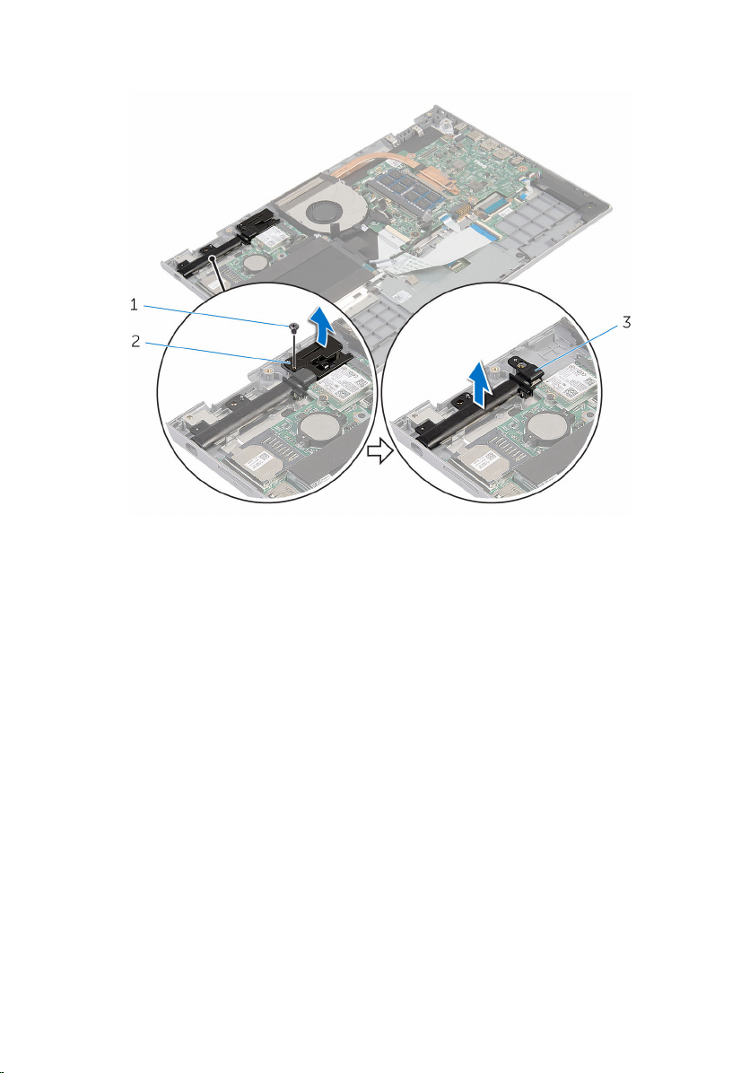
3 Lift the stylus holder off the palmrest and keyboard assembly.
1 screw 2 stylus lock
3 stylus holder
69
Page 70

Replacing the stylus-holder assembly
WARNING: Before working inside your computer, read the safety
information that shipped with your computer and follow the steps in
Before working inside your computer. After working inside your
computer, follow the instructions in After working inside your
computer. For more safety best practices, see the Regulatory
Compliance home page at www.dell.com/regulatory_compliance.
Procedure
1 Place the stylus holder and stylus lock on the palmrest and keyboard
assembly.
2 Align the screw hole on the stylus holder and stylus lock with the screw
hole on the palmrest and keyboard assembly.
3 Replace the screw that secures the stylus holder and stylus lock to the
palmrest and keyboard assembly.
4 Insert the stylus into the stylus holder and push to snap it in place.
Post-requisites
1 Replace the display assembly.
2 Replace the battery.
3 Replace the base cover.
70
Page 71

Removing the palm rest and keyboard assembly
WARNING: Before working inside your computer, read the safety
information that shipped with your computer and follow the steps in
Before working inside your computer. After working inside your
computer, follow the instructions in After working inside your
computer. For more safety best practices, see the Regulatory
Compliance home page at www.dell.com/regulatory_compliance.
Prerequisites
1 Remove the base cover.
2 Remove the battery.
3 Follow the procedure from step 1 to step 3 in “Removing the hard drive”.
4 Remove the stylus-holder assembly.
5 Remove the keyboard daughter-board.
6 Remove the touch pad.
7 Remove the fan.
8 Remove the heat sink.
9 Remove the I/O board.
10 Remove the speakers.
11 Remove the display assembly.
12 Remove the power-adapter port.
13 Remove the system board.
Procedure
After performing the steps in prerequisites we are left with the palmrest and
keyboard assembly.
71
Page 72
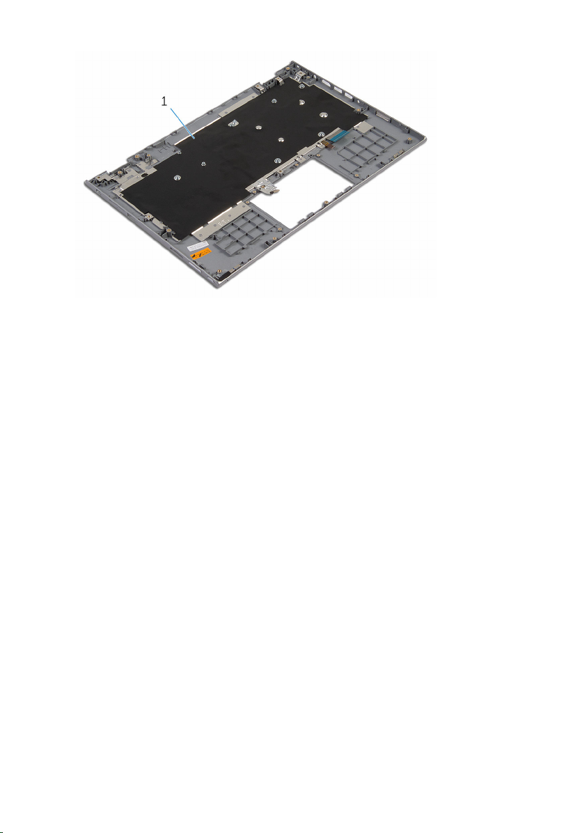
1 palmrest and keyboard assembly
72
Page 73

Replacing the palm rest and keyboard assembly
WARNING: Before working inside your computer, read the safety
information that shipped with your computer and follow the steps in
Before working inside your computer. After working inside your
computer, follow the instructions in After working inside your
computer. For more safety best practices, see the Regulatory
Compliance home page at www.dell.com/regulatory_compliance.
Procedure
Place the palmrest and keyboard assembly on a flat surface with the keyboard
facing down.
Post-requisites
1 Replace the system board.
2 Replace the power-adapter port.
3 Replace the display assembly.
4 Replace the speakers.
5 Replace the I/O board.
6 Replace the heat sink.
7 Replace the fan.
8 Replace the touch pad.
9 Replace the keyboard daughter-board.
10 Replace the stylus-holder assembly.
11 Follow the procedure from step 4 to step 6 in “Replacing the hard drive”.
12 Replace the battery.
13 Replace the base cover.
73
Page 74
Removing the display panel
WARNING: Before working inside your computer, read the safety
information that shipped with your computer and follow the steps in
Before working inside your computer. After working inside your
computer, follow the instructions in After working inside your
computer. For more safety best practices, see the Regulatory
Compliance home page at www.dell.com/regulatory_compliance.
Prerequisites
1 Remove the base cover.
2 Remove the battery.
3 Remove the display assembly.
Procedure
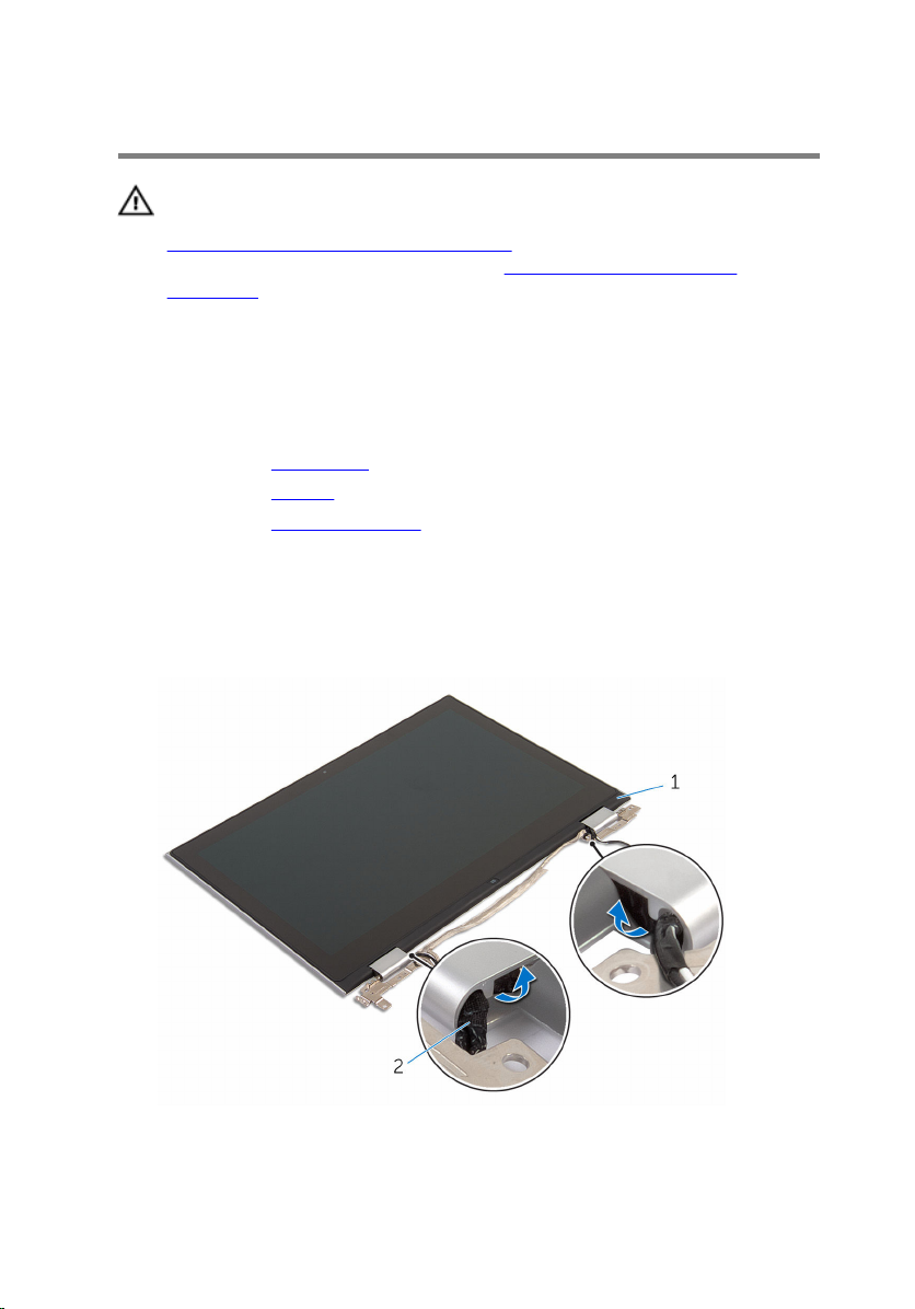
1 Remove the display cable from the routing guides inside the hinge
covers.
74
1 display panel assembly 2 display cable
Page 75
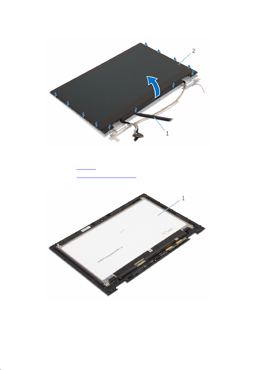
2 Using a plastic scribe, pry the display-panel assembly off the display
back-cover and antenna assembly.
1 plastic scribe 2 display-panel assembly
3 Remove the camera.
4 Remove the Windows-button board.
After performing the above steps, we are left with the display panel.
1 display panel
75
Page 76

Replacing the display panel
WARNING: Before working inside your computer, read the safety
information that shipped with your computer and follow the steps in
Before working inside your computer. After working inside your
computer, follow the instructions in After working inside your
computer. For more safety best practices, see the Regulatory
Compliance home page at www.dell.com/regulatory_compliance.
Procedure
1 Place the display panel on a flat surface.
2 Replace the Windows-button board.
3 Replace the camera.
4 Route the display cable through the routing guides inside the hinge
covers.
5 Align the display-panel assembly with the display back-cover and
antenna assembly and gently snap the display back-cover and antenna
assembly into place.
Post-requisites
1 Replace the display assembly.
2 Replace the battery.
3 Replace the base cover.
76
Page 77

Removing the display hinges
WARNING: Before working inside your computer, read the safety
information that shipped with your computer and follow the steps in
Before working inside your computer. After working inside your
computer, follow the instructions in After working inside your
computer. For more safety best practices, see the Regulatory
Compliance home page at www.dell.com/regulatory_compliance.
Prerequisites
1 Remove the base cover.
2 Remove the battery.
3 Remove the display assembly.
4 Remove the display back-cover and antenna assembly.
Procedure
1 Place the display-back cover and antenna assembly on a flat surface.
2 Remove the antenna cables from the routing guide on the hinge cover.
3 Remove the screws that secure the display hinges to the display back-
cover and antenna assembly.
77
Page 78
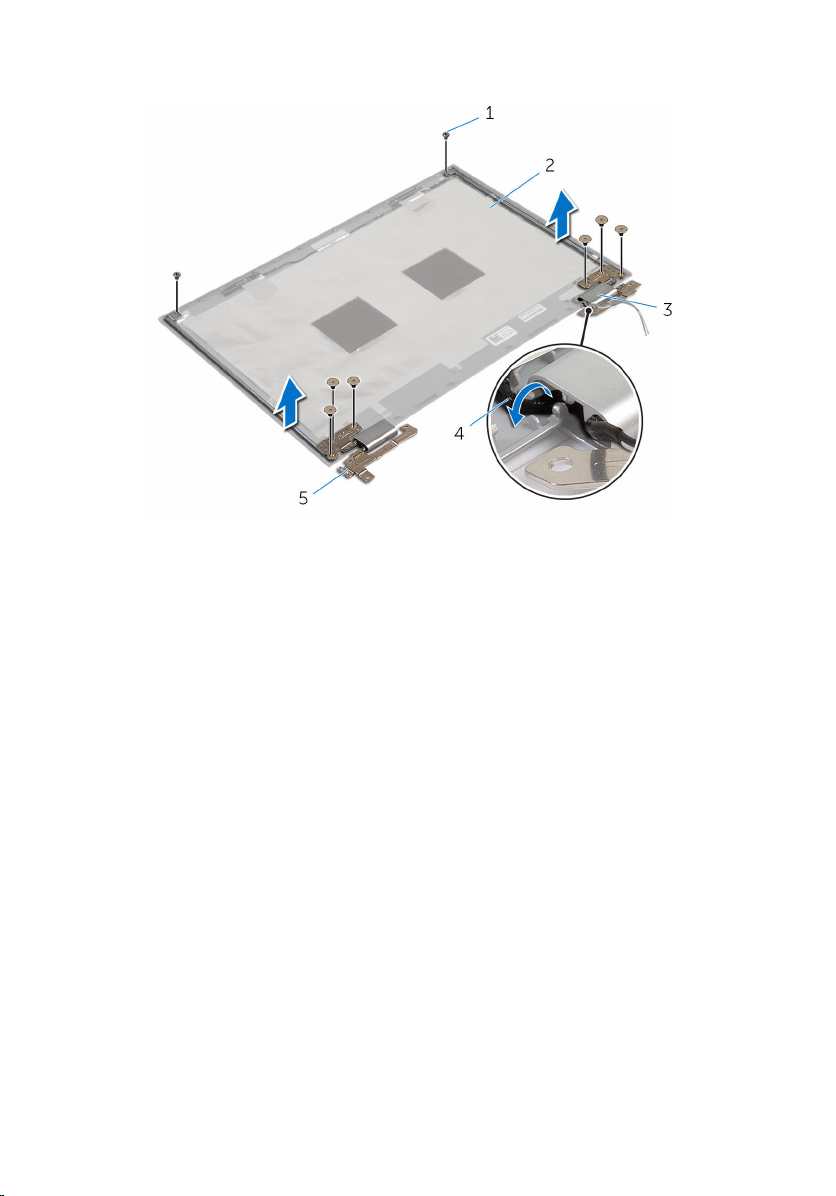
4 Lift the display hinges off the display back-cover and antenna assembly.
1 screws (8) 2 display back-cover and
antenna assembly
3 hinge covers (2) 4 antenna cables (2)
5 display hinges (2)
78
Page 79

Replacing the display hinges
WARNING: Before working inside your computer, read the safety
information that shipped with your computer and follow the steps in
Before working inside your computer. After working inside your
computer, follow the instructions in After working inside your
computer. For more safety best practices, see the Regulatory
Compliance home page at www.dell.com/regulatory_compliance.
Procedure
1 Align the screw holes on the display hinges with the screw holes on the
display back-cover and antenna assembly.
2 Replace the screws that secure the display hinges to the display back-
cover and antenna assembly.
3 Route the antenna cables through the routing guide on the hinge cover
and secure it in place.
Post-requisites
1 Replace the display back-cover and antenna assembly.
2 Replace the display assembly.
3 Replace the battery.
4 Replace the base cover.
79
Page 80

Removing the display backcover and antenna assembly
WARNING: Before working inside your computer, read the safety
information that shipped with your computer and follow the steps in
Before working inside your computer. After working inside your
computer, follow the instructions in After working inside your
computer. For more safety best practices, see the Regulatory
Compliance home page at www.dell.com/regulatory_compliance.
Prerequisites
1 Remove the base cover.
2 Remove the battery.
3 Remove the display assembly.
4 Remove the display panel.
5 Remove the display hinges.
Procedure
After performing the steps in prerequisites we are left with the display backcover and antenna assembly.
80
Page 81
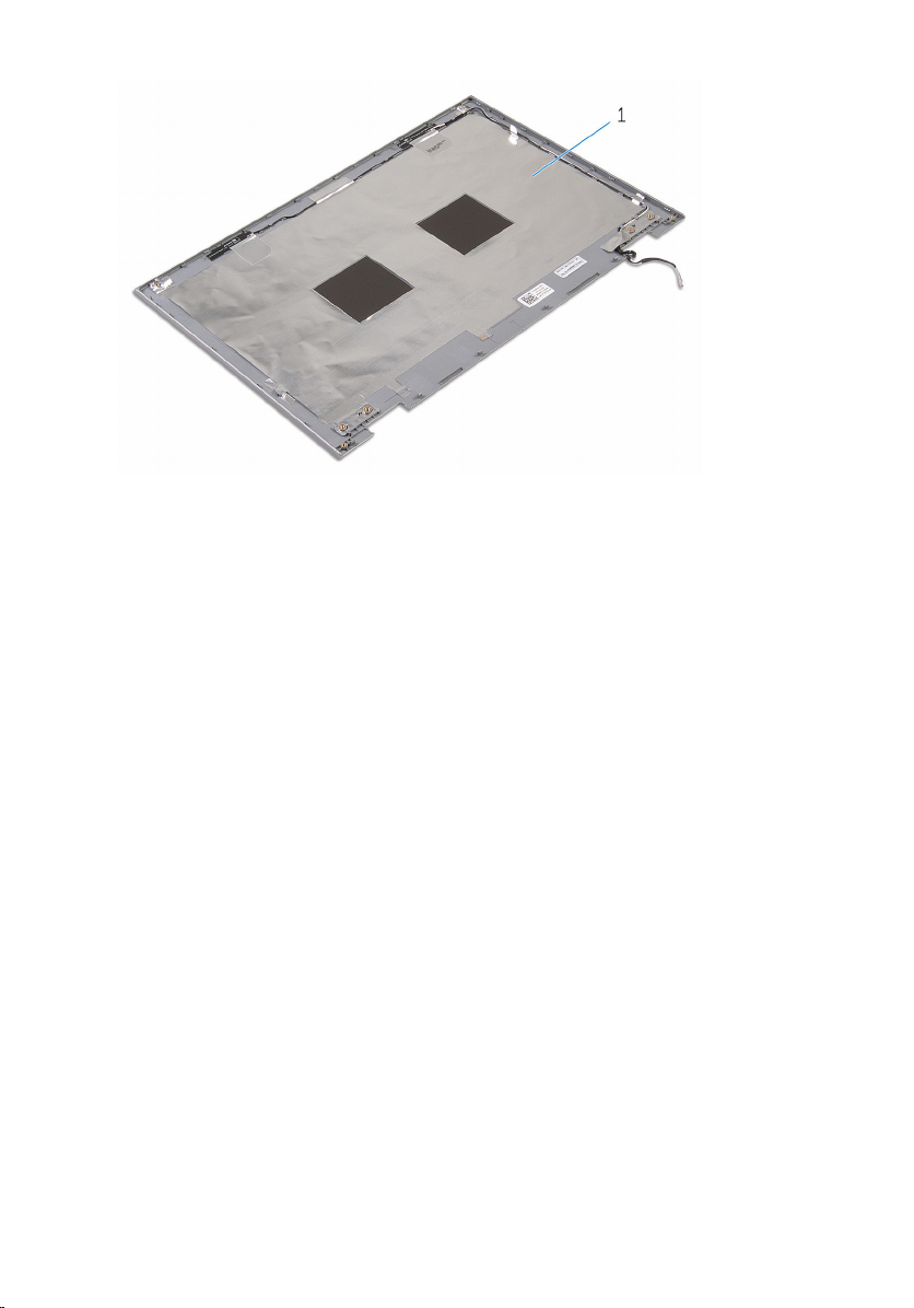
1 display back-cover and antenna
assembly
81
Page 82

Replacing the display backcover and antenna assembly
WARNING: Before working inside your computer, read the safety
information that shipped with your computer and follow the steps in
Before working inside your computer. After working inside your
computer, follow the instructions in After working inside your
computer. For more safety best practices, see the Regulatory
Compliance home page at www.dell.com/regulatory_compliance.
Procedure
Place the display back-cover and antenna assembly on a flat surface.
Post-requisites
1 Replace the display hinges.
2 Replace the display panel.
3 Replace the display assembly.
4 Replace the battery.
5 Replace the base cover.
82
Page 83

Removing the camera
WARNING: Before working inside your computer, read the safety
information that shipped with your computer and follow the steps in
Before working inside your computer. After working inside your
computer, follow the instructions in After working inside your
computer. For more safety best practices, see the Regulatory
Compliance home page at www.dell.com/regulatory_compliance.
Prerequisites
1 Remove the base cover.
2 Remove the battery.
3 Remove the display assembly.
4 Remove the display back-cover and antenna assembly.
Procedure
CAUTION: Place the display-panel assembly on a soft and clean
surface to avoid scratching the display.
1 Place the display-panel assembly face down on a flat surface.
2 Using a plastic scribe, pry the camera module off the display bezel.
83
Page 84
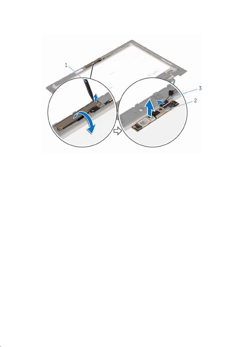
3 Turn the camera over and disconnect the camera cable from the camera
module.
1 plastic scribe 2 camera
3 camera cable
84
Page 85

Replacing the camera
WARNING: Before working inside your computer, read the safety
information that shipped with your computer and follow the steps in
Before working inside your computer. After working inside your
computer, follow the instructions in After working inside your
computer. For more safety best practices, see the Regulatory
Compliance home page at www.dell.com/regulatory_compliance.
Procedure
1 Connect the camera cable to the camera module.
2 Using the alignment post place the camera module on the display bezel
and snap it into place.
Post-requisites
1 Replace the display back-cover and antenna assembly.
2 Replace the display assembly.
3 Replace the battery.
4 Replace the base cover.
85
Page 86

Removing the Windowsbutton board
WARNING: Before working inside your computer, read the safety
information that shipped with your computer and follow the steps in
Before working inside your computer. After working inside your
computer, follow the instructions in After working inside your
computer. For more safety best practices, see the Regulatory
Compliance home page at www.dell.com/regulatory_compliance.
Prerequisites
1 Remove the base cover.
2 Remove the battery.
3 Remove the display assembly.
4 Remove the display back-cover and antenna assembly.
Procedure
CAUTION: Place the display-panel assembly on a soft and clean
surface to avoid scratching the display.
1 Place the display-panel assembly face down on a flat surface.
2 Remove the screw that secures the Windows-button board to the display
bezel.
3 Turn the Windows-button board over.
4 Peel off the adhesive tape and disconnect the Windows-button board
cable from the Windows-button board.
86
Page 87
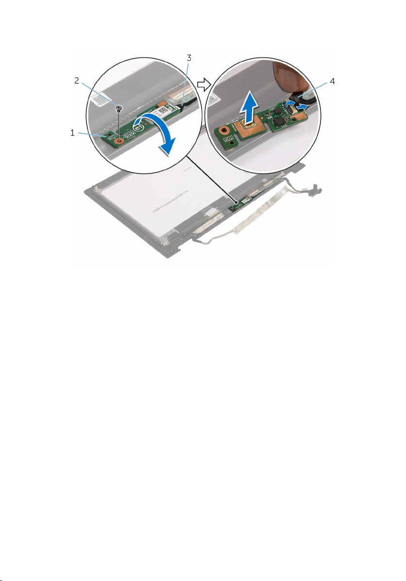
5 Lift the Windows-button board off the display bezel.
1 windows-button board 2 screw
3 windows-button board
cable
4 adhesive tape
87
Page 88

Replacing the Windowsbutton board
WARNING: Before working inside your computer, read the safety
information that shipped with your computer and follow the steps in
Before working inside your computer. After working inside your
computer, follow the instructions in After working inside your
computer. For more safety best practices, see the Regulatory
Compliance home page at www.dell.com/regulatory_compliance.
Procedure
1 Slide the Windows-button board cable into the connector on the
Windows-button board and press down the latch to secure the cable.
2 Turn the Windows-button board and align the screw hole on the
Windows-button board with the screw hole on the display bezel.
3 Replace the screw that secures the Windows-button board to the display
bezel.
4 Turn the display-panel assembly over.
Post-requisites
1 Replace the display back-cover and antenna assembly .
2 Replace the display assembly.
3 Replace the battery.
4 Replace the base cover.
88
Page 89

Removing the display cable
WARNING: Before working inside your computer, read the safety
information that shipped with your computer and follow the steps in
Before working inside your computer. After working inside your
computer, follow the instructions in After working inside your
computer. For more safety best practices, see the Regulatory
Compliance home page at www.dell.com/regulatory_compliance.
Prerequisites
1 Remove the base cover.
2 Remove the battery.
3 Remove the display assembly.
4 Remove the display back-cover and antenna assembly.
5 Remove the camera.
Procedure
1 Peel off the adhesive tape and lift the latch to disconnect the display
cable from the display panel.
2 Disconnect the Windows-button board cable.
3 Peel off the adhesive tape, lift the connector latch to disconnect the
touch-screen board cable from the touch-screen board.
4 Remove the camera cable from the routing guides on the display bezel.
5 Lift the connector latch and disconnect the display cable from the touch
board.
6 Note the display cable routing and remove the display cable from the
routing guides on the display bezel.
89
Page 90
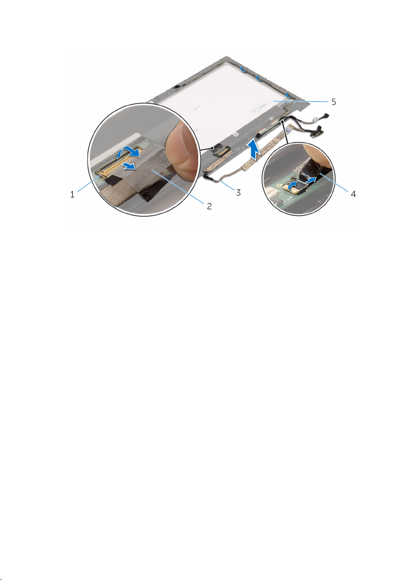
7 Lift the display cable off the display bezel.
1 connector latch for display
cable
3 display cable 4 touch-screen board cable
5 display panel
2 adhesive tape
90
Page 91

Replacing the display cable
WARNING: Before working inside your computer, read the safety
information that shipped with your computer and follow the steps in
Before working inside your computer. After working inside your
computer, follow the instructions in After working inside your
computer. For more safety best practices, see the Regulatory
Compliance home page at www.dell.com/regulatory_compliance.
Procedure
1 Route the display cable through the routing guides on the display bezel.
2 Slide the display cable into the connector on the touch board and press
down the latch to secure the cable.
3 Route the camera cable through the routing guides on the display bezel.
4 Adhere the adhesive tape, connect the touch-screen board cable to the
touch-screen board and press down the connector latch to secure the
cable.
5 Slide the Windows-button board cable into the connector on the
Windows-button board and press down the latch to secure the cable.
6 Adhere the adhesive tape on the Windows-button board connector.
Post-requisites
1 Replace the display back-cover and antenna assembly.
2 Replace the display assembly.
3 Replace the camera.
4 Replace the battery.
5 Replace the base cover.
91
Page 92

Flashing the BIOS
You may need to flash (update) the BIOS when an update is available or when
you replace the system board. To flash the BIOS:
1 Turn on the computer.
2 Go to www.dell.com/support.
3 Click Product Support, enter the Service Tag of your computer and click
Submit.
NOTE: If you do not have the Service Tag, use the auto-detect
feature or manually browse for your computer model.
4 Click Drivers & downloads.
5 Select the operating system installed on your computer.
6 Scroll down the page and expand BIOS.
7 Click Download File to download the latest version of the BIOS for your
computer.
8 Save the file and, once the download is complete, navigate to the folder
where you saved the BIOS update file.
9 Double-click the BIOS update file icon and follow the instructions on the
screen.
92
Page 93

Getting help and contacting Dell
Self-help resources
You can get information and help on Dell products and services using these
self-help resources:
Information about Dell products and
services
Windows 8.1 and Windows 10 Dell Help & Support app
Windows 10 Get started app
Windows 8.1 Help + Tips app
Accessing help in Windows 8,
Windows 8.1, and Windows 10
Accessing help in Windows 7
Online help for operating system
Troubleshooting information, user
manuals, setup instructions, product
specifications, technical help blogs,
drivers, software updates, and so on
www.dell.com
In Windows search, type Help and
Support, and press Enter.
Click Start → Help and Support.
www.dell.com/support/windows
www.dell.com/support/linux
www.dell.com/support
Learn about your operating system,
setting up and using your computer,
data backup, diagnostics, and so on.
See Me and My Dell at
www.dell.com/support/manuals.
93
Page 94

Contacting Dell
To contact Dell for sales, technical support, or customer service issues, see
www.dell.com/contactdell.
NOTE: Availability varies by country and product, and some services may
not be available in your country.
NOTE: If you do not have an active internet connection, you can find
contact information on your purchase invoice, packing slip, bill, or Dell
product catalog.
94
 Loading...