

Page 1

Dell Chromebook 11 - 3120
Disassembly and Reassembly Guide
Warning: This manual is intended for use by a Dell Certified Technician.
Damage due to servicing that is not authorized by Dell is not covered by your
warranty. Read and follow the safety instructions that came with the product.
Page 2

Notes, cautions, and warnings
: A NOTE indicates important information that helps you make better use of your computer.
NOTE
CAUTION
how to avoid the problem.
WARNING: A WARNING indicates a potential for property damage, personal injury, or death.
: A CAUTION indicates either potential damage to hardware or loss of data and tells you
Copyright © 2015 Dell Inc. All rights reserved. This product is protected by U.S. and international copyright and
intellectual property laws. Dell™ and the Dell logo are trademarks of Dell Inc. in the United States and/or other
jurisdictions. All other marks and names mentioned herein may be trademarks of their respective companies.
2015 - 03
Rev. A00
Page 3

Chassis
This section provides information about the chassis for the Dell™ Chromebook 11 (3120) system.
1/1
Page 4
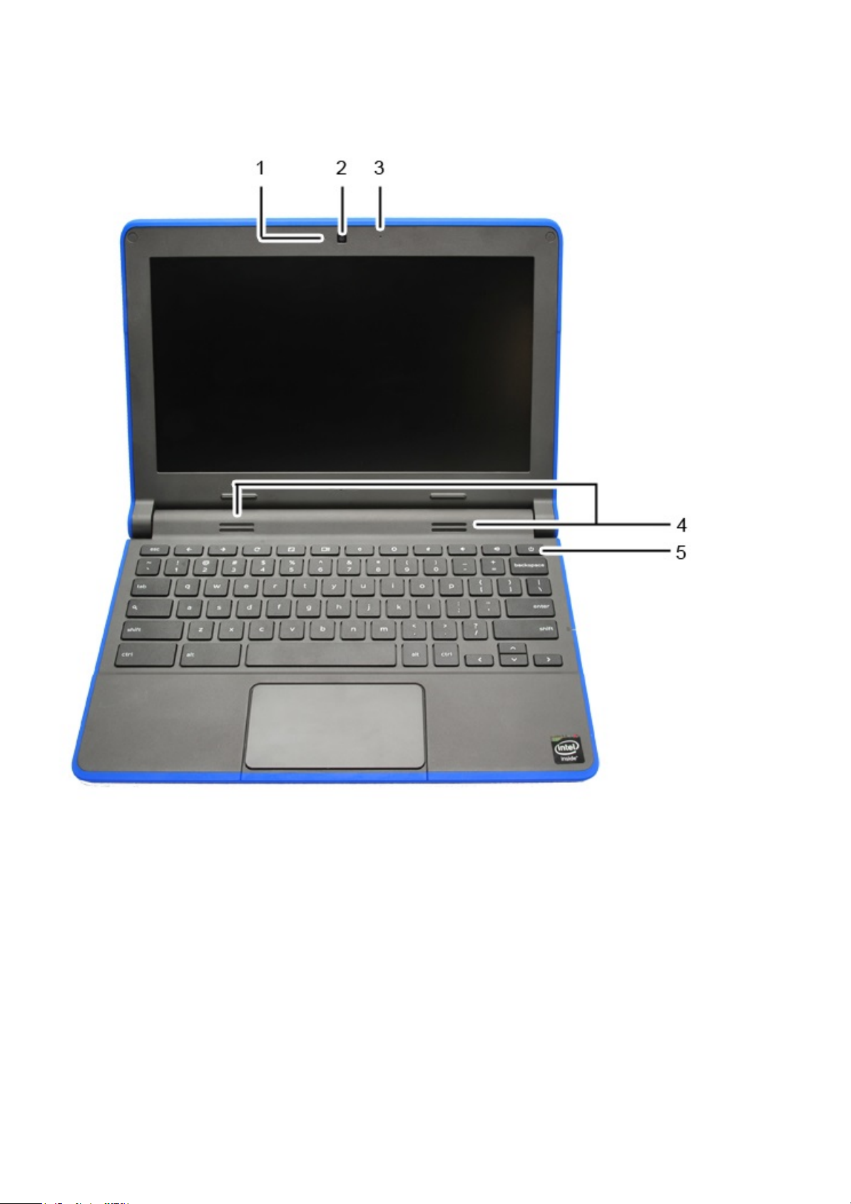
TopView
The Dell™ Chromebook™ 11 (3120) system top view and features are as below:
1/2
Page 5
Chassis Top View Features and Locations
Label Description
1 Webcam LED
2 Webcam
3 Microphone
4 Speakers
5 Power Button
6 A-Cover LED ( Interactivity LED)
2/2
Page 6
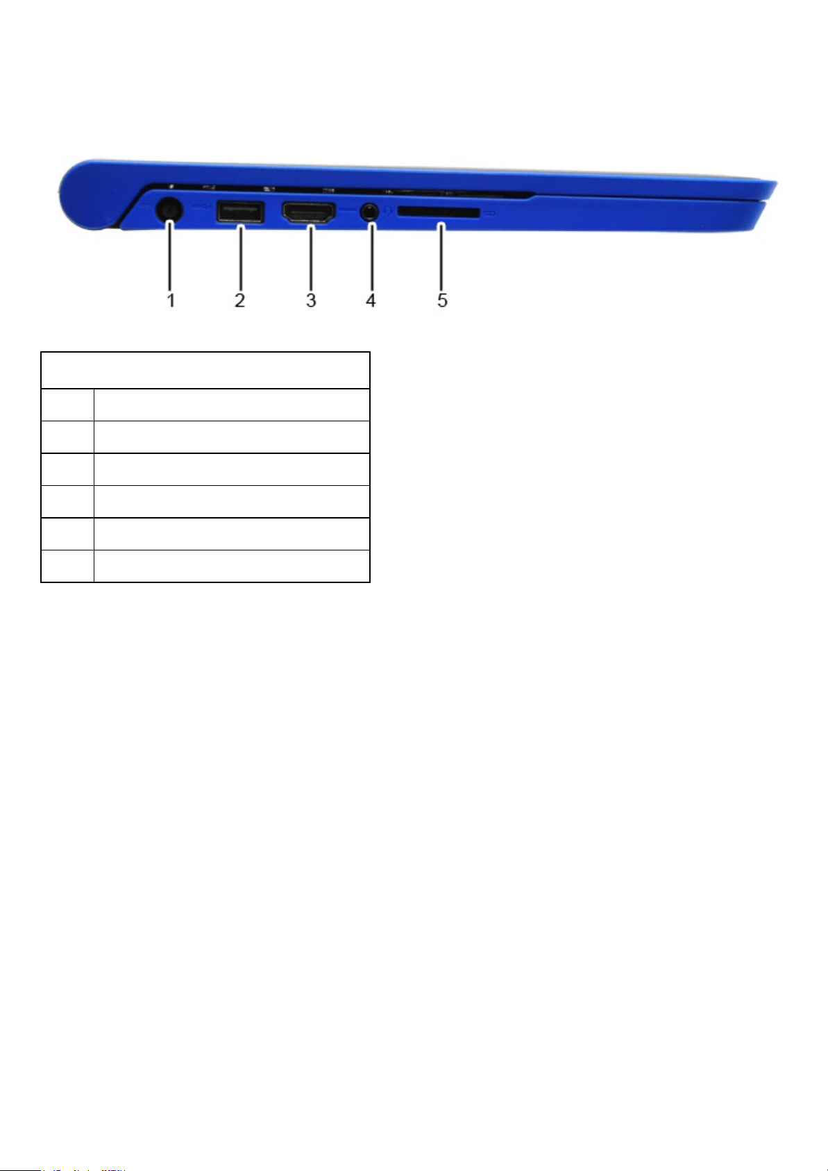
LeftView
The Dell™ Chromebook™ 11 (3120) system left view and features are as below:
Chassis Left View Features and Locations
Label Description
1 DC-in Jack
2 USB 3.0 with BC (Battery Charging) 1.2
3 HDMI
4 Audio in Jack
5 SD Card Reader
1/1
Page 7
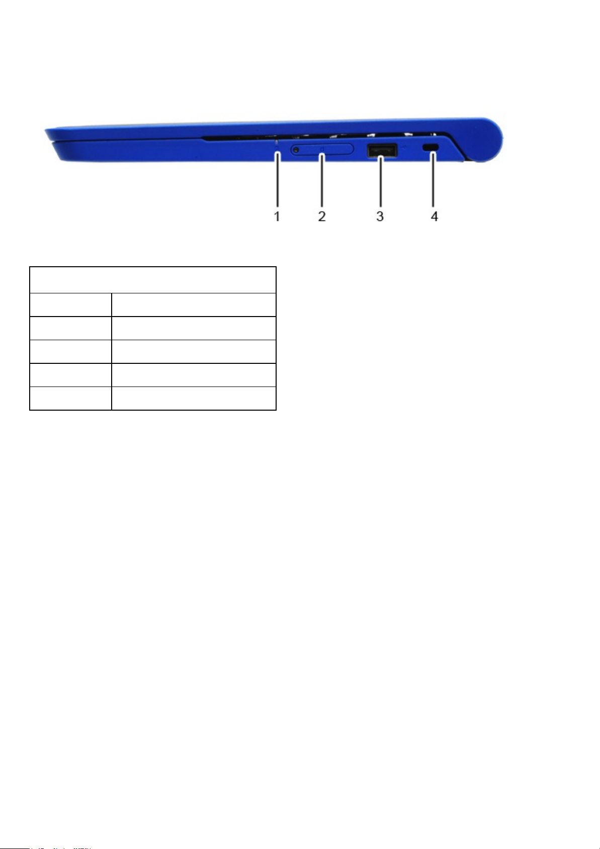
RightView
The Dell™ Chromebook™ 11 (3120) system right view and features are as below:
Chassis Right View Features and Locations
Label Description
1 Battery LED
2 SIM Card Slot
3 USB 2.0
4 K-Lock Slot
1/1
Page 8
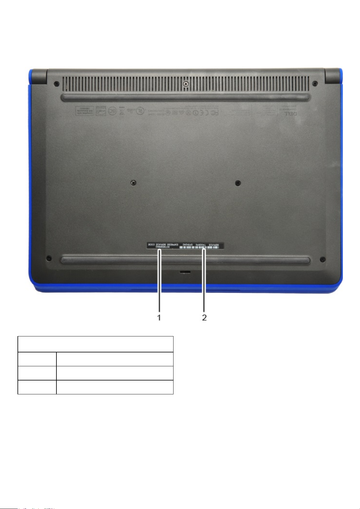
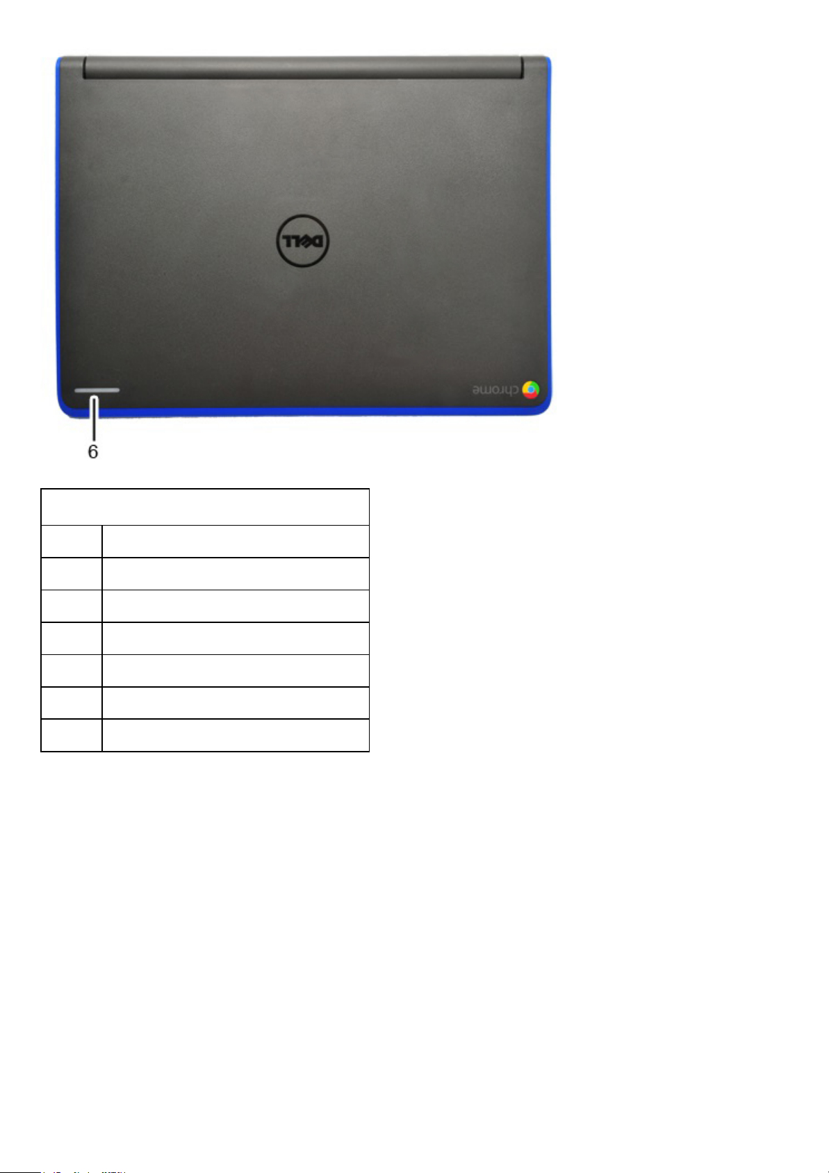
BottomView
The Dell™ Chromebook™ 11 (3120) system bottom view and features are as below:
Chassis Bottom View Features and Locations
Label Description
1 Express Service Code
2 Service Tag
1/1
Page 9
ChassisLED
This page contains all the information about LEDs on Dell™ Chromebook™ 11 (3120).
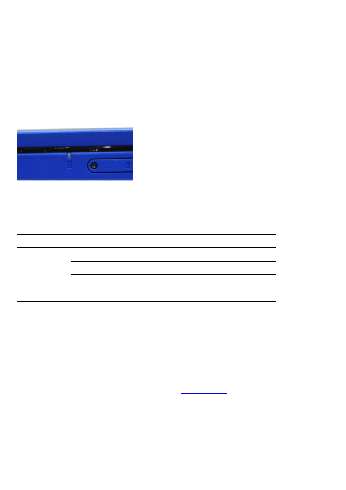
BatteryLED
The battery status LED light is located at the right side of the chassis, as shown in the image below.
Battery Status LED
LED Light Status Description
Off
AC powered, charge level higher than 97%
Battery powered, charge level higher than 10%
Battery powered, charge level less than 10%, machine in S5 state
White AC powered, charge level less than 97%, charging
Amber Battery powered, charge level less than 10%, machine in S0 or S3 state
Blinking Amber Battery error
DellActivityLight
Chromebook 11 (3120) comes with a 7 color Dell Activity light LEDs outside of the LCD back cover which
can be use for interactivity between students and teachers.
For more information about Dell Activity Light, please visit Dell Bright Light
in the software section.
Location of the Dell Activity Light as highlighted in the image below.
1/4
Page 10
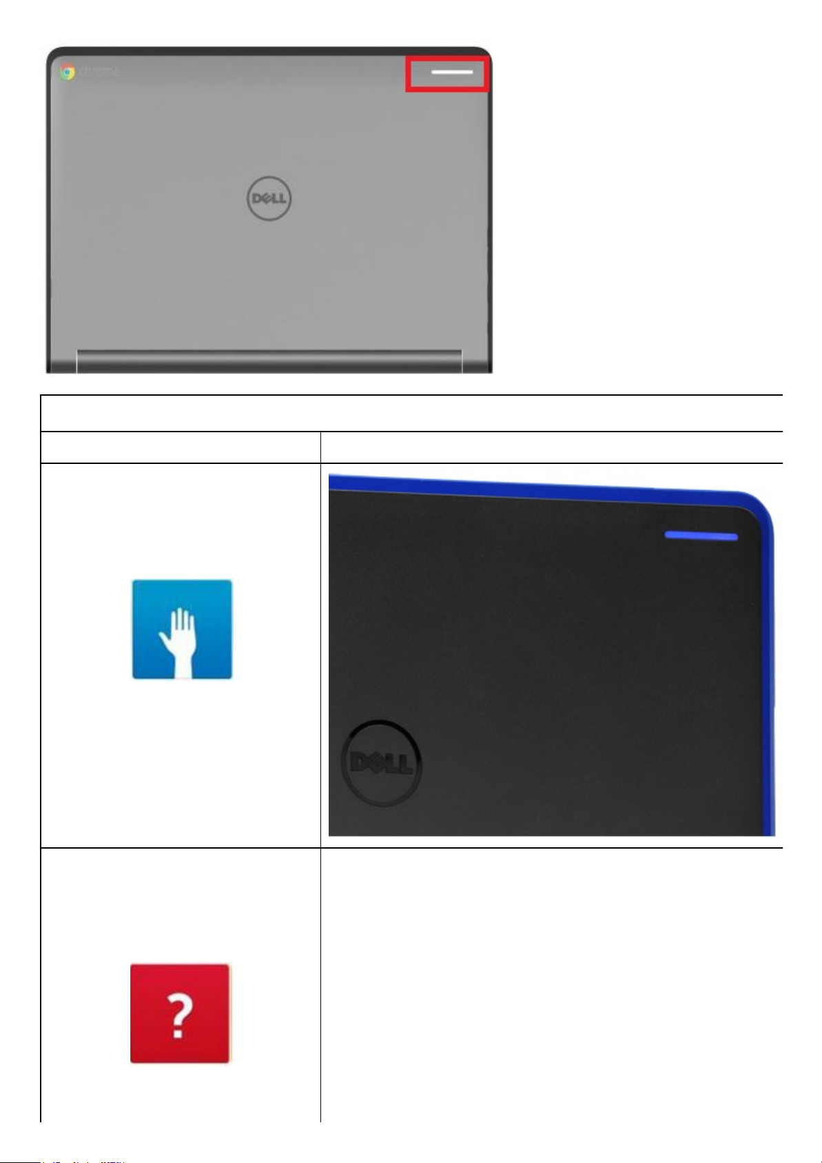
Dell Activity Light
LED Light Status Chassis LED Light
Blue
Red
2/4
Page 11
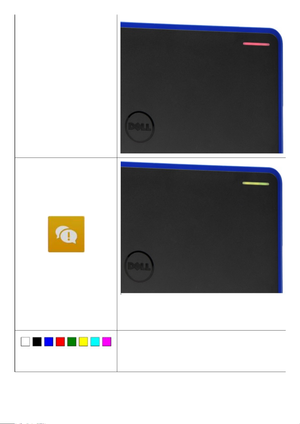
Yellow
Others
WebcamLED
3/4
Page 12
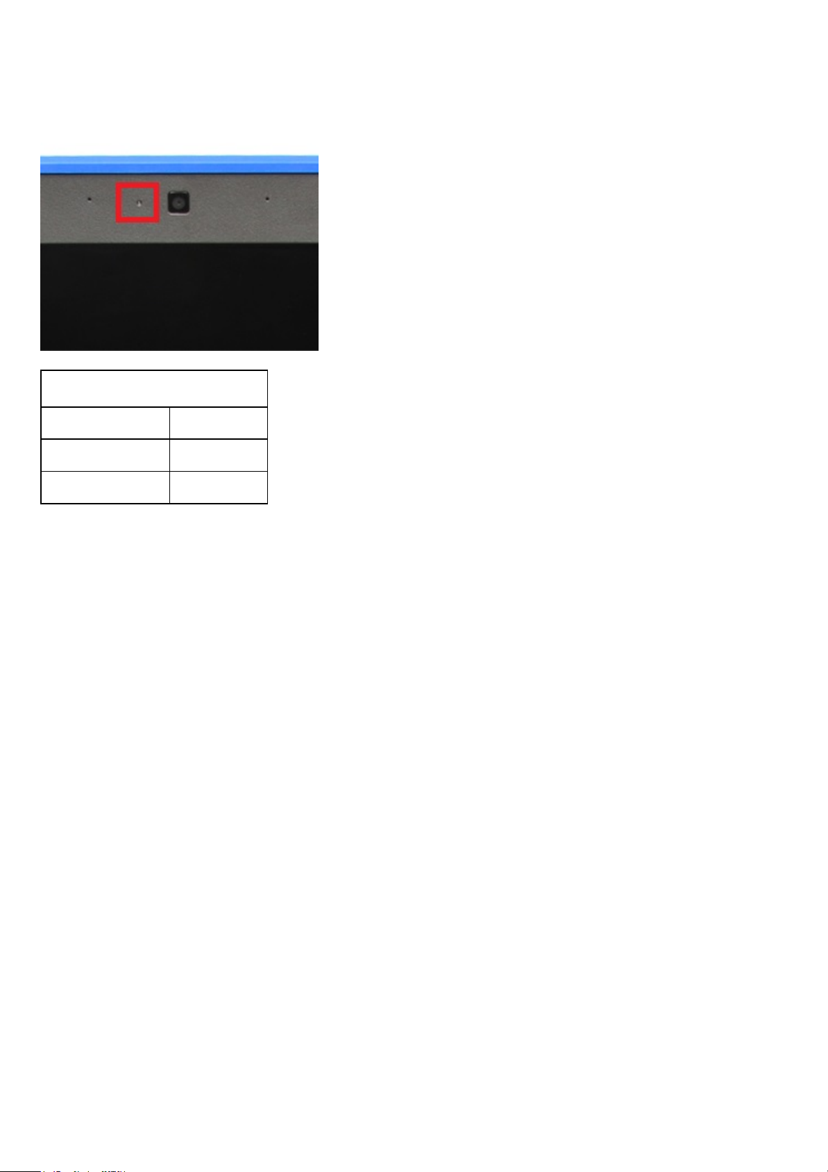
Chromebook 11 (3120) will have a webcam LED indicator on the LCD bezel, as shown in the image below.
Webcam Status LED
LED Light Status Description
Off Webcam off
White Webcam on
4/4
Page 13

FieldServiceInformation
This section covers field service information.
The information in this section is specifically for field service personnel who perform installation, diagnosis,
and repair activities. Field personnel are required to know the issues and procedures in this document
whether or not they perform all the service tasks.
Information in this section is required knowledge, but should never override regional or local policies and
procedures
The sections and primary pages in this document are as follows:
Safety Precautions — Generic safety precautions for every service event.
Tools & Utilities — Hand tools needed to service the Dell™ Chromebook™ 11 (3120).
Need to Know — Information and instructions for the Chromebook that requires additional
attention. This section may contain critical call outs, New, Unique, Different and Difficult (NUDDs),
and common error codes.
Diagnostic — Available diagnostic tools for the Chromebook 11 (3120).
Disassembly and Reassembly — Instructions for removing each replaceable part, with information
needed before, during, and after parts replacement.
RMA Shim — Information and instructions which must be done whenever a hardware replacement
takes place.
1/1
Page 14
SafetyPrecautions
Observe the following safety precautions when you perform any installation or break/fix procedures
involving disassembly or reassembly:
Turn off the system and all attached peripherals.
Disconnect the system and all attached peripherals from AC power, and then remove the battery.
Disconnect all network cables, telephone or telecommunications lines from the system.
Use a wrist grounding strap and mat when working inside any computer system to avoid
electrostatic discharge (ESD) damage.
After removing a system component, carefully place the removed component on an anti-static mat.
Wear shoes with non-conductive rubber soles to help reduce the risk of being shocked or seriously
injured in an electrical accident.
StandbyPower
Dell products with standby power must be completely unplugged before the case is opened. Systems that
incorporate standby power are essentially powered while turned off. The internal power enables the system
to be remotely turned on (wake on LAN), suspended into a sleep mode, and have other advanced power
management features.
After you unplug a system and before you remove components, wait approximately 30 to 45 seconds to
allow the charge to drain from the circuits. Remove the battery from portable computers.
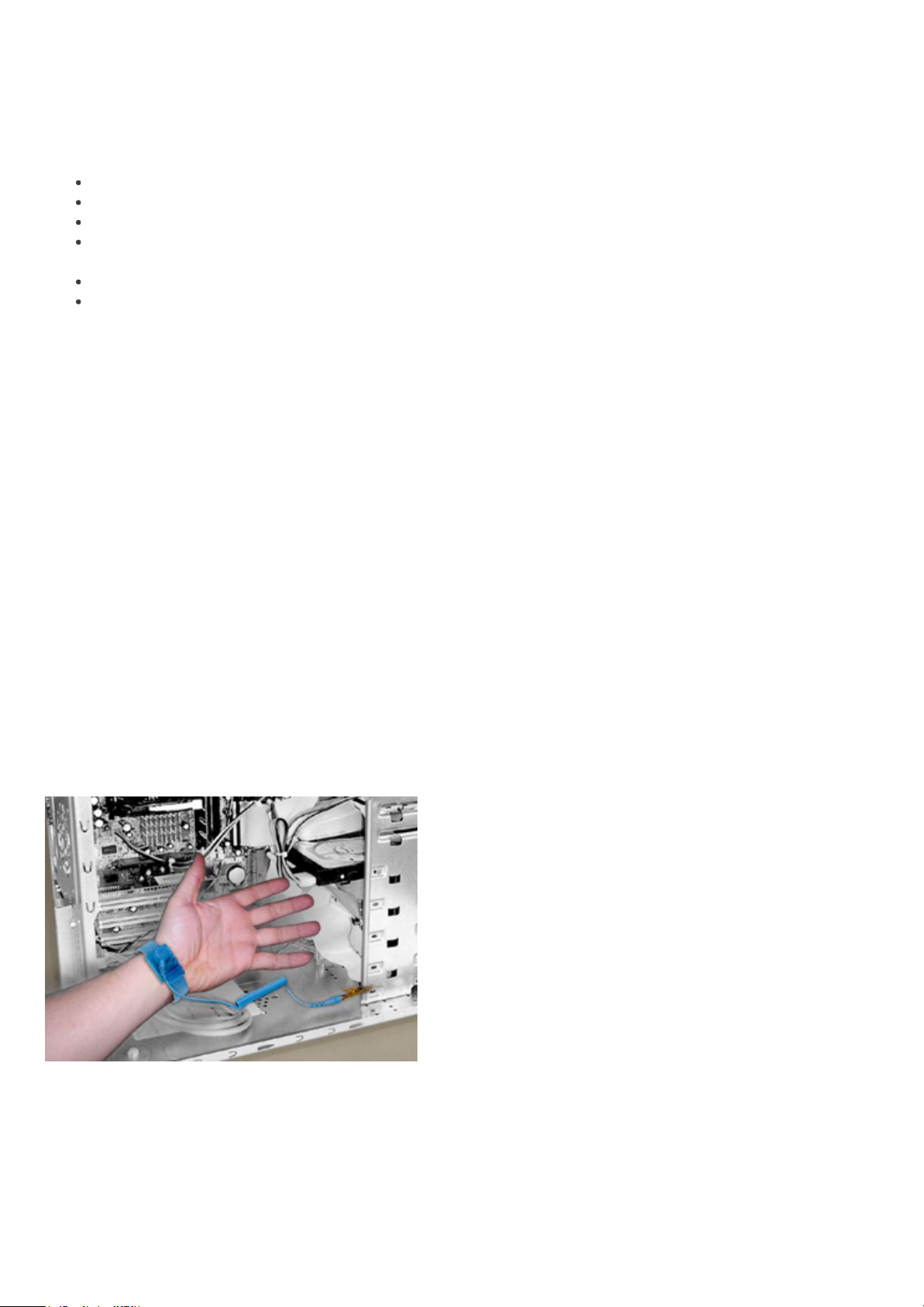
Bonding
Bonding is a method for connecting two or more grounding conductors to the same electrical potential.
This is done through the use of a Field Service ESD kit. When connecting a bonding wire, always ensure
that it is connected to bare metal and never to a painted or non-metal surface. The wrist strap should be
secure and in full contact with your skin, and be sure to always remove all jewelry such as watches,
bracelets, or rings prior to bonding yourself and the equipment.
Bonding Properly
ElectrostaticDischargeProtection
ESD is a major concern when you handle electronic components, especially sensitive components such as
expansion cards, processors, memory DIMMs, and system boards. Very slight charges can damage circuits
in ways that may not be obvious, such as intermittent problems or a shortened product life span. As the
industry pushes for lower power requirements and increased density, ESD protection is an increasing
1/7
Page 15
concern.
Due to the increased density of semiconductors used in recent Dell products, the sensitivity to static
damage is now higher than in earlier Dell products. For this reason some previously approved methods of
handling parts are no longer applicable.
There are two recognized types of ESD damage: catastrophic and intermittent failures.
Catastrophic —The damage causes an immediate and complete loss of device functionality. An
example of catastrophic failure is a memory DIMM that has received a static shock and immediately
generates a "No POST/No Video" symptom with a beep code emitted for missing or nonfunctional
memory.
NOTE: Catastrophic failures represent approximately 20 percent of ESD-related failures.
Intermittent —The DIMM receives a static shock, but the tracing is merely weakened and does not
immediately produce outward symptoms related to the damage. The weakened trace may take
weeks or months to melt, and in the meantime may cause degradation of memory integrity,
intermittent memory errors, etc.
NOTE: Intermittent failures represent approximately 80 percent of ESD-related failures. The
high rate of intermittent failures means that most of the time when damage occurs, it is not
immediately recognizable.
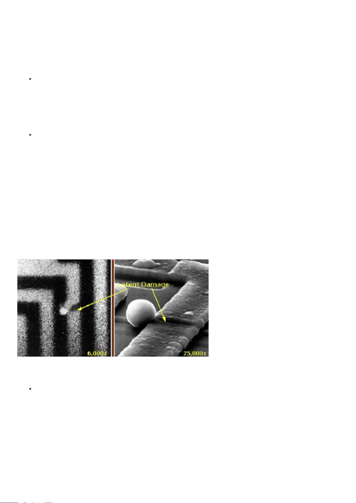
The more difficult type of damage to recognize and troubleshoot is the intermittent (also called latent or
“walking wounded”) failure. The following image shows an example of intermittent damage to a memory
DIMM trace. Although the damage is done, the symptoms may not become an issue or cause permanent
failure symptoms for some time after the damage occurs.
Intermittent (Latent) Damage to a Wiring Trace
Do the following to prevent ESD damage:
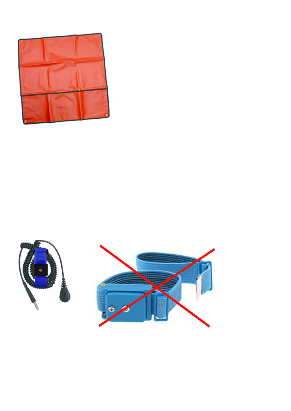
Use a wired ESD wrist strap that is properly grounded.
The use of wireless anti-static straps is no longer allowed; they do not provide adequate protection.
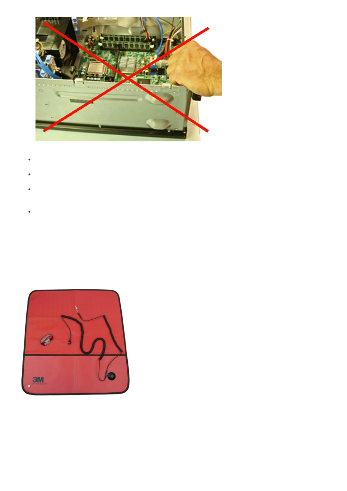
Touching the chassis before handling parts does not ensure adequate ESD protection on parts with
increased sensitivity to ESD damage.
Chassis "Bare Metal" Grounding (Unacceptable)
2/7
Page 16
Handle all static-sensitive components in a static-safe area. If possible, use anti-static floor pads and
workbench pads.
When handling static-sensitive components, grasp them by the sides, not the top. Avoid touching
pins and circuit boards.
When unpacking a static-sensitive component from its shipping carton, do not remove the
component from the anti-static packing material until you are ready to install the component. Before
unwrapping the anti-static packaging, be sure to discharge static electricity from your body.
Before transporting a static-sensitive component, place it in an anti-static container or packaging.
TheESDFieldServiceKit
The unmonitored Field Service kit is the most commonly used. Each Field Service kit includes three main
components: anti-static mat, wrist strap, and bonding wire.
ESD Field Service Kit
AntiStaticMat
The anti-static mat is dissipative and should be used to safely place parts on during service procedures.
When using an anti-static mat, your wrist strap should be snug and the bonding wire should be connected
to the mat and to bare-metal on the system being worked on. Once deployed properly, service parts can
be removed from the ESD bag and placed directly on the mat. Remember, the only safe place for ESDsensitive items are in your hand, on the ESD mat, in the system, or inside a bag.
3/7
Page 17
Anti-Static Mat
WristStrapandBondingWire
The wrist strap and bonding wire can be either directly connected between your wrist and bare metal on
the hardware if the ESD mat is not required, or connected to the anti-static mat to protect hardware that is
temporarily placed on the mat. The physical connection of the wrist strap and bonding wire between your
skin, the ESD mat, and the hardware is known as bonding. Use only Field Service kits with a wrist strap, mat,
and bonding wire.Never use wireless wrist straps.
Always be aware that the internal wires of a wrist strap are prone to damage from normal wear and tear,
and must be checked regularly with a wrist strap tester in order to avoid accidental ESD hardware damage.
It is recommended to test the wrist strap and bonding wire a minimum of once per week.
Wrist Strap and Bonding Wire
Wireless ESD Strap (Unacceptable)
ESDWristStrapTester
4/7
Page 18
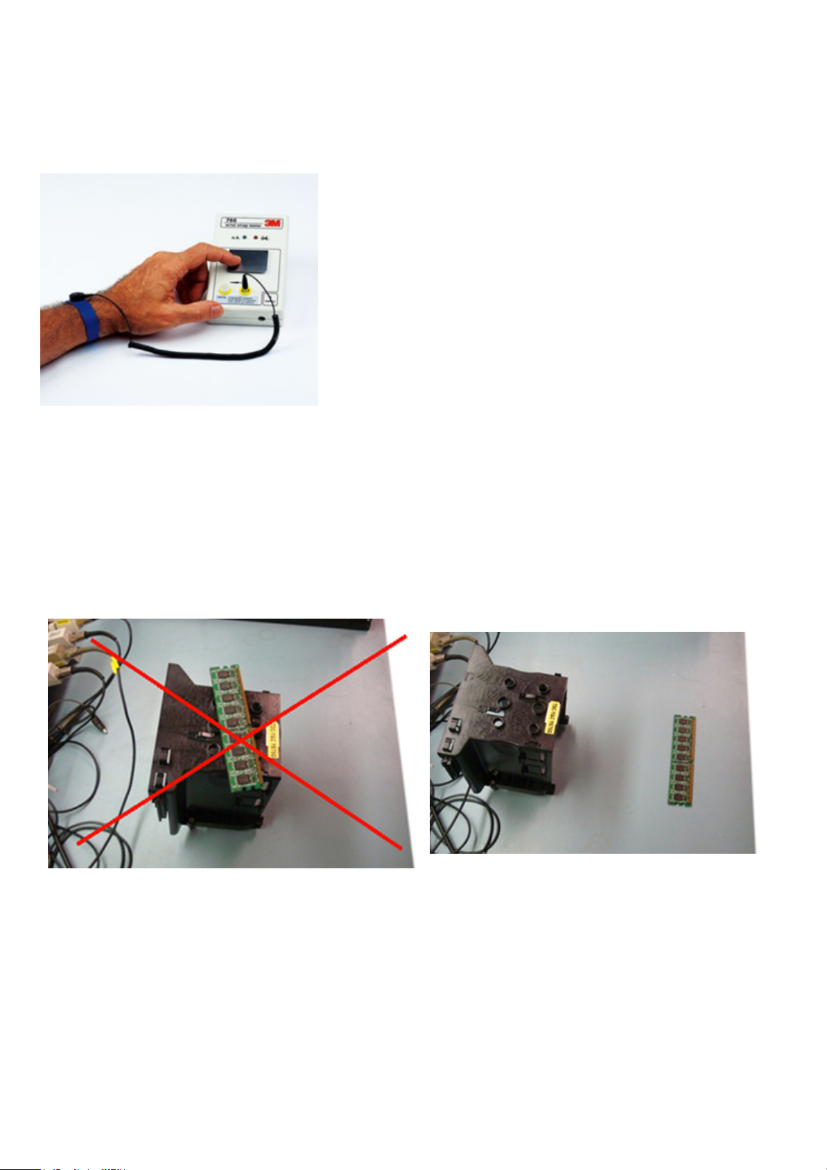
The wires inside of an ESD strap are prone to damage over time. When using an unmonitored kit, it is best
InsulatorElements
It is critical to keep ESD sensitive devices, such as plastic heat sink casings, away from internal parts that are
insulators and often highly charged.
Unacceptable — DIMM lying on an insulator part
(plastic heat sink shroud)
Acceptable — DIMM separated from the
insulator part
ConsidertheWorkingEnvironment
Before deploying the ESD Field Service kit, assess the situation at the customer location. For example,
deploying the kit for a server environment is different than for a desktop or portable environment. Servers
are typically installed in a rack within a data center; desktops or portables are typically placed on office
desks or cubicles.
Always look for a large open flat work area that is free of clutter and large enough to deploy the ESD kit
with additional space to accommodate the type of system that is being repaired. The workspace should
practice to regularly test the strap prior to each service call, and at a minimum, test once per week. A wrist
strap tester is the best method for doing this test. If you do not have your own wrist strap tester, check
with your regional office to find out if they have one. To perform the test, plug the wrist-strap’s bondingwire into the tester while it is strapped to your wrist and push the button to test. A green LED is lit if the test
is successful; a red LED is lit and an alarm sounds if the test fails.
Wrist Strap Tester
5/7
Page 19

also be free of insulators that can cause an ESD event. On the work area, insulators such as Styrofoam and
other plastics should always be moved at least 12 inches or 30 centimeters away from sensitive parts before
physically handling any hardware components.
ESDPackaging
All ESD-sensitive devices must be shipped and received in static-safe packaging. Metal, static-shielded bags
are preferred. However, you should always return the damaged part using the same ESD bag and packaging
that the new part arrived in. The ESD bag should be folded over and taped shut and all the same foam
packing material should be used in the original box that the new part arrived in.
ESD-sensitive devices should be removed from packaging only at an ESD-protected work surface, and
parts should never be placed on top of the ESD bag because only the inside of the bag is shielded. Always
place parts in your hand, on the ESD mat, in the system, or inside an anti-static bag.
ESD Packaging
TransportingSensitiveComponents
When transporting ESD-sensitive components such as replacement parts or parts to be returned to Dell, it
is critical to place these parts in anti-static bags for safe transport.
ESDProtectionSummary
It is strongly suggested that all field service engineers use the traditional wired ESD grounding wrist strap
and protective anti-static mat at all times when servicing Dell products. In addition, it is critical that
engineers keep sensitive parts separate from all insulator parts while performing service and that they use
6/7
Page 20

anti-static bags for transporting sensitive components.
LiftingEquipment
WARNING: Do not lift greater than 50 pounds. Always obtain assistance from another person or
persons, or use a mechanical lifting device.
Adhere to the following guidelines when lifting equipment:
1. Get a firm balanced footing. Keep your feet apart for a stable base, and point your toes out.
2. Bend your knees. Do not bend at the waist.
3. Tighten stomach muscles. Abdominal muscles support your spine when you lift, offsetting the force
of the load.
4. Lift with your legs, not your back.
5. Keep the load close. The closer it is to your spine, the less force it exerts on your back.
6. Keep your back upright, whether lifting or setting down the load. Do not add the weight of your
body to the load. Avoid twisting your body and back.
7. Follow the same techniques in reverse to set the load down.
7/7
Page 21
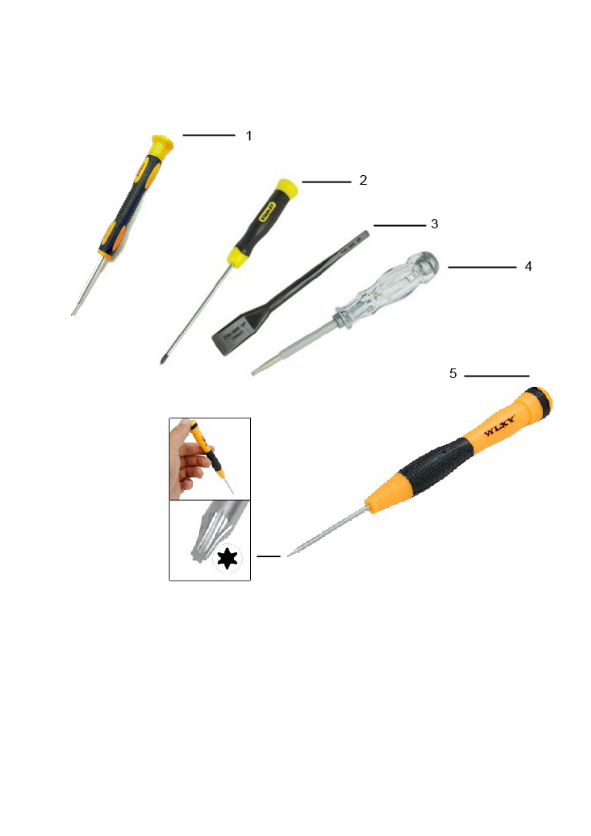
ToolsRequired
A set of required and optional tools are necessary to service the product.
1. Small Phillips-head screwdriver, size #1
2. Small Phillips-head screwdriver, size #1
3. Plastic scribe
4. Small flat-head screwdriver
5. Tork 5 screwdriver
1/1
Page 22

DisassemblyandReassembly
This section covers all the disassembly and reassembly of the Dell™ Chromebook™ 11 (3120).
1/1
Page 23
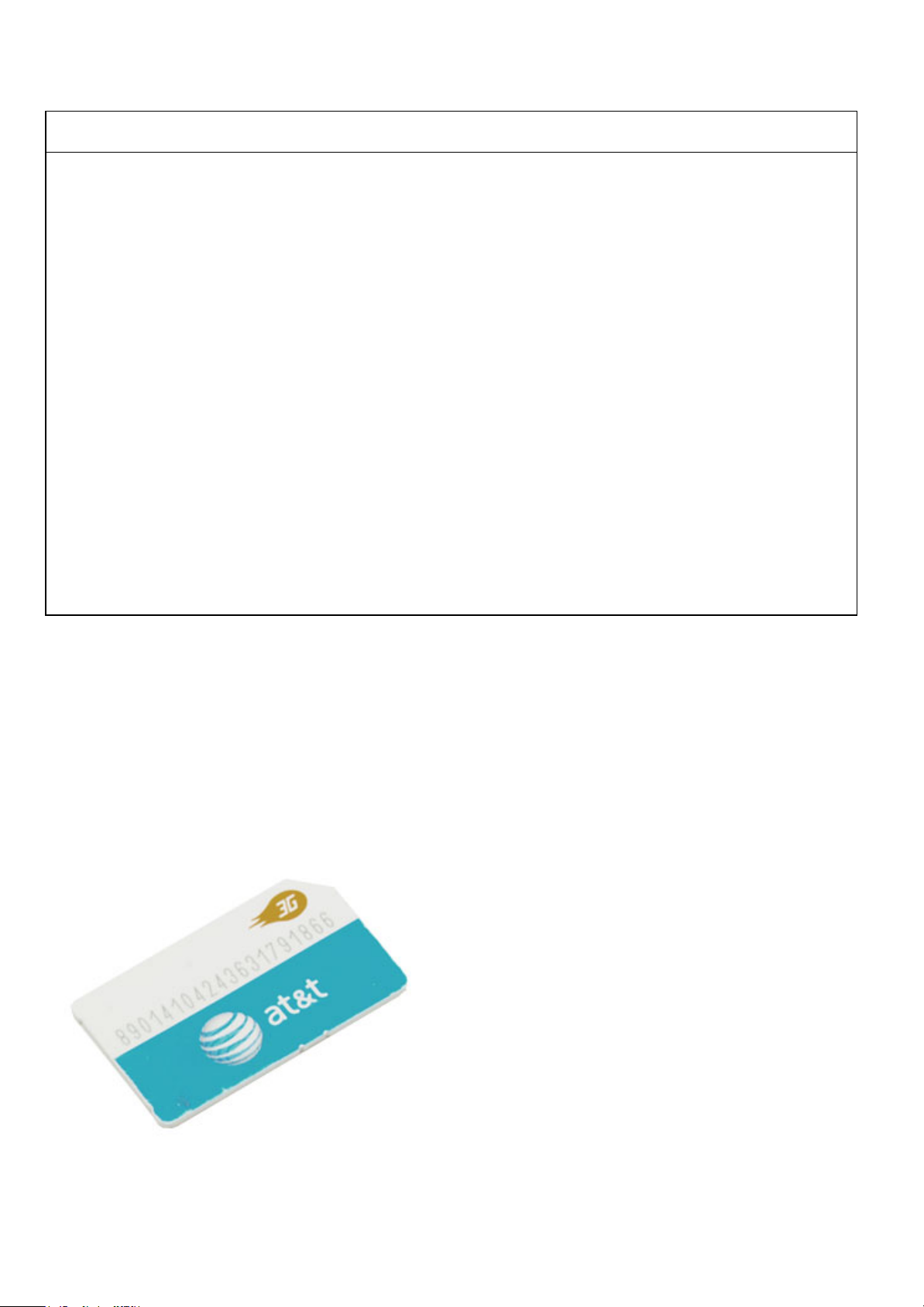
SimCardDisassembly
Sim Card Disassembly Video
PREREQUISITES
Pre-removal parts:
1. None
Sim Card
Establishing image.
1/5
Page 24
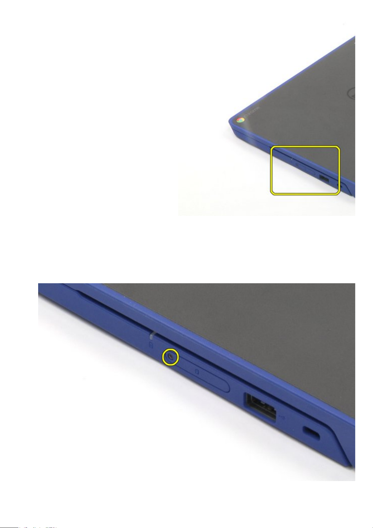
SimCardDisassembly
1. Remove the T5 screw.
2. Remove the cover.
2/5
Page 25
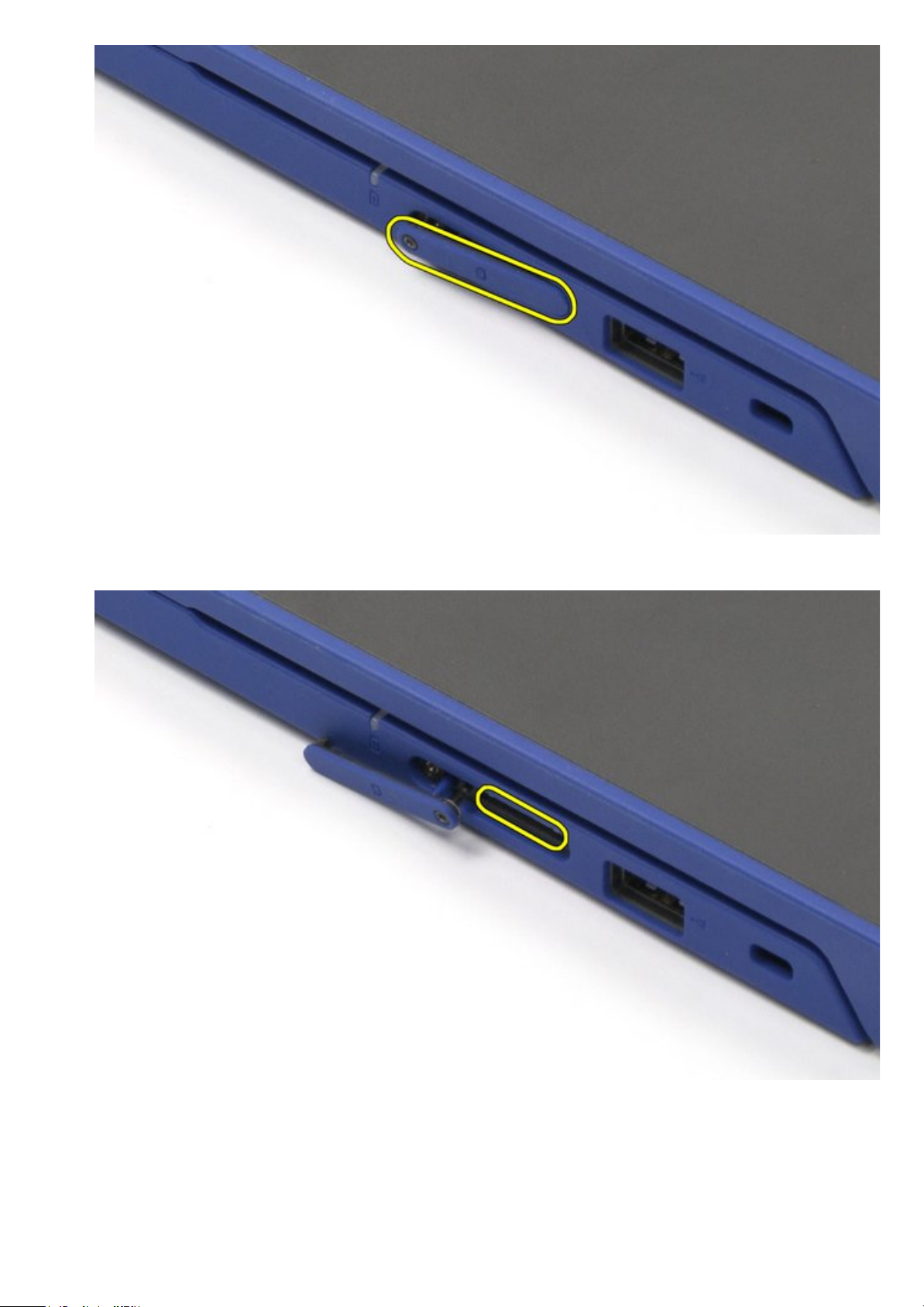
3. Use the push pin to eject the sim card.
4. Remove the sim card.
3/5
Page 26
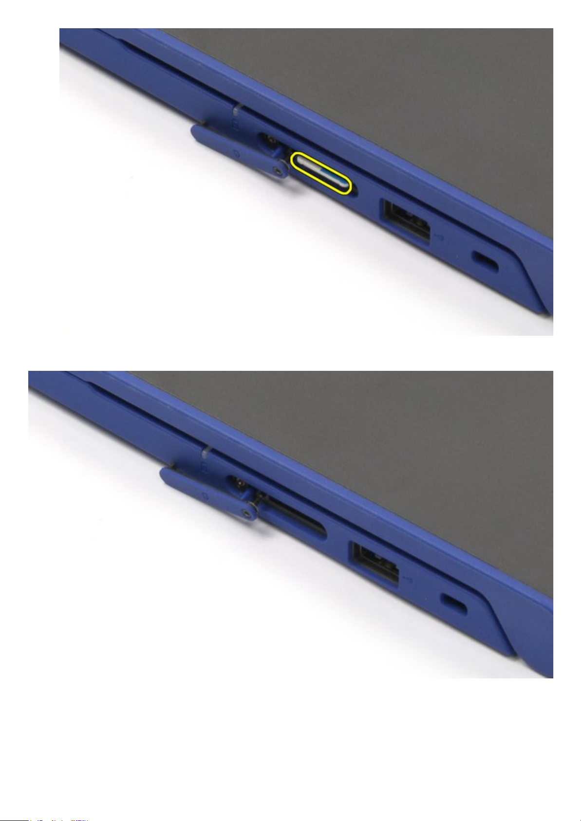
The removal is complete.
SimCardReassembly
1. Insert the sim card.
2. Close the cover.
4/5
Page 27

3. Tighten the T5 screw.
5/5
Page 28

BottomCoverDisassembly
Bottom Cover Disassembly Video
PREREQUISITES
Pre-removal parts:
1. None
Bottom Cover
Establishing image.
1/4
Page 29

BottomCoverDisassembly
1. Loosen the seven (7) screws securing the bottom cover.
2. Pry up the bottom cover carefully, starting from the top corners.
2/4
Page 30

3. Lift up and remove the bottom cover.
The removal is complete.
3/4
Page 31

BottomCoverReassembly
1. Replace the bottom cover back into its original location.
2. Gently push the cover back to make sure that it is secured in place.
3. Tighten all seven (7) screws.
4/4
Page 32

BatteryDisassembly
Battery Disassembly Video
PREREQUISITES
Pre-removal parts:
1. Bottom Cover
Battery Establishing image.
1/4
Page 33

BatteryDisassembly
1. Remove the two (2) screws that secure the battery in place.
2. Slowly pull the battery to disconnect the battery cable from system board, and remove the battery
from the system board.
2/4
Page 34

The removal is complete.
BatteryReassembly
1. Place the battery back into its original location.
2. Reconnect the battery cable.
3/4
Page 35

3. Tighten the two (2) screws to secure the battery in place.
AfterServiceInstructions
1. Reconnect the system to its electrical outlet.
2. Turn on the system and attached peripherals.
3. Let the system boot.
4/4
Page 36

WLANCardDisassembly
WLAN Card Disassembly Video
PREREQUISITES
Pre-removal parts:
1. Bottom Cover
2. Battery
WLAN Card Establishing image.
1/5
Page 37

WLANCardDisassembly
1. Remove the cable holder securing the antenna cables.
2. Disconnect the antenna cables from the WLAN card.
2/5
Page 38

3. Remove one screw securing the WLAN card.
4. Remove the WLAN card.
3/5
Page 39

The removal is complete.
WLANCardReassembly
1. Place the WLAN card back into its original location.
2. Reconnect the antenna cable.
4/5
Page 40

3. Tighten the one (1) screw to secure the WLAN card in place.
AfterServiceInstructions
1. Reconnect the system to its electrical outlet.
2. Turn on the system and attached peripherals.
3. Let the system boot.
5/5
Page 41

I/ODaughterBoardDisassembly
I/O Daughter Board Disassembly Video
PREREQUISITES
Pre-removal parts:
1. Bottom Cover
2. Battery
3. WLAN Card
I/O Daughter Board Establishing image.
1/4
Page 42

I/ODaughterBoardDisassembly
1. Carefully disconnect the Flex cable.
2. Remove the two (2) screws securing the I/O daughter board in place.
2/4
Page 43

3. Lift up and remove the I/O daughter board.
The removal is complete.
3/4
Page 44

I/ODaughterBoardReassembly
1. Place the I/O daughter board back into its original location.
2. Reconnect the Flex cable.
3. Tighten the two (2) screws to secure the I/O daughter board in place.
AfterServiceInstructions
1. Reconnect the system to its electrical outlet.
2. Turn on the system and attached peripherals.
3. Let the system boot.
4/4
Page 45

SystemBoardDisassembly
System Board Disassembly Video
PREREQUISITES
Remove the following parts:
1. Bottom cover
2. Battery
3. WLAN card
System Board Establishing image.
1/5
Page 46

SystemBoardDisassembly
1. Disconnect the 1) I/O cable, 2) touch pad, 3) keyboard, 4) speaker, 5) DC-in jack, and 6) eDP cables.
2/5
Page 47

2. Remove the nine screws.
3. Lift up and remove the system board.
3/5
Page 48

The removal is complete.
NOTE: Please perform RMA Shim after the system board replacement. For more information, please
see RMA Shim
.
NOTE:
The RMA Shim USB key will be dispatched or bundled together with the replacement system board. The
RMA Shim USB software on the USB key is the service-lite version, which will only contain the
4/5
Page 49

Shop Floor and Google Required Test Module.
After completing the break-fix event, always return the RMA Shim USB key together with the faulty
system board.
SystemBoardReassembly
1. Place the system board back into its original location.
2. Reconnect all the cables.
3. Tighten the nine screws to secure the system board in place.
AfterServiceInstructions
1. Reconnect the system to its electrical outlet.
2. Turn on the system and attached peripherals.
3. Let the system boot.
5/5
Page 50

SpeakersDisassembly
Speakers Disassembly Video
PREREQUISITES
Pre-removal parts:
1. Bottom Cover
2. Battery
Speakers Establishing image.
1/4
Page 51

SpeakersDisassembly
1. Disconnect the keyboard, touchpad, and I/O cables.
2. Disconnect the speaker connector from the system board.
2/4
Page 52

3. Unthread the speaker cable and remove the speakers.
The removal is complete.
3/4
Page 53

SpeakersReassembly
1. Place the speakers back into their original location.
2. Reconnect all the cables.
AfterServiceInstructions
1. Reconnect the system to its electrical outlet.
2. Turn on the system and attached peripherals.
3. Let the system boot.
4/4
Page 54

DCInJackDisassembly
DC-In Jack Disassembly Video
PREREQUISITES
Pre-removal parts:
1. Bottom Cover
2. Battery
DC-In Jack Establishing image.
1/4
Page 55

DCInJackDisassembly
1. Disconnect the DC-In jack connector from the system board.
2. Remove the screw securing the DC-In jack in place.
2/4
Page 56

3. Lift up the DC-In jack.
The removal is complete.
3/4
Page 57

DCInJackReassembly
1. Place the DC-In jack back into its original location.
2. Tighten the screw to secure the DC-in jack in place.
3. Reconnect all the cables.
AfterServiceInstructions
1. Reconnect the system to its electrical outlet.
2. Turn on the system and attached peripherals.
3. Let the system boot.
4/4
Page 58

LCDAssemblyDisassembly
LCD Assembly Disassembly Video
PREREQUISITES
Pre-removal parts:
1. Bottom Cover
2. Battery
LCD Assembly Establishing image.
1/5
Page 59

LCDAssemblyDisassembly
1. Disconnect the eDP and wireless cables.
2. Remove the four (4) screws.
2/5
Page 60

3. Lift up the two (2) hinges.
4. Lift up the palm rest and remove it.
3/5
Page 61

The removal is complete.
LCDAssemblyReassembly
1. Place the LCD Assembly back into its original location on the palm rest.
2. Reconnect all the cables.
4/5
Page 62

3. Tighten the four (4) screws to the system base.
AfterServiceInstructions
1. Reconnect the system to its electrical outlet.
2. Turn on the system and attached peripherals.
3. Let the system boot.
5/5
Page 63

LCDBezelDisassembly
LCD Bezel Disassembly Video
PREREQUISITES
Pre-removal parts:
1. Bottom Cover
2. Battery
3. LCD Assembly
LCD Bezel Establishing image.
1/5
Page 64

LCDBezelDisassembly
1. Remove the two (2) mylar screw covers.
NOTE: The screw cover on the LCD bezel is made up of a mylar sticker, and it can be hard to
remove with just a normal plastic scribe. To remove this screw, simply use the regular Philips
2/5
Page 65

driver and puncture the mylar cover.
2. Remove the two (2) screws.
3. Pry from the bottom and work your way up.
3/5
Page 66

4. Remove the bezel.
The removal is complete.
4/5
Page 67

LCDBezelReassembly
1. Place the LCD Bezel back into its original location.
2. Tighten the two (2) screws to secure the bezel in place.
3. Replace the mylar screw covers.
5/5
Page 68

LCDPanelDisassembly
LCD Panel Disassembly Video
PREREQUISITES
Pre-removal parts:
1. Bottom Cover
2. Battery
3. LCD Assembly
LCD Panel Establishing image.
1/5
Page 69

LCDPanelDisassembly
1. Remove the four (4) screws.
2. Lift the LCD up and rotate it 180 degrees.
2/5
Page 70

3. Remove the connector.
4. Remove the LCD.
3/5
Page 71

The removal is complete.
LCDPanelReassembly
1. Place the LCD Panel back into its original location and reconnect the connector.
2. Tighten the four (4) screws to secure the LCD panel in place.
4/5
Page 72

AfterServiceInstructions
1. Reconnect the system to its electrical outlet.
2. Turn on the system and attached peripherals.
3. Let the system boot.
5/5
Page 73

CameraDisassembly
Camera Disassembly Video
PREREQUISITES
Pre-removal parts:
1. Bottom Cover
2. Battery
3. LCD Assembly
Camera Establishing image.
1/4
Page 74

CameraDisassembly
1. Pry the camera out from the sticky base.
2. Disconnect the camera cable and remove the camera.
2/4
Page 75

The removal is complete.
CameraReassembly
1. Place the camera back into its original location.
2. Reconnect the connector.
3/4
Page 76

AfterServiceInstructions
1. Reconnect the system to its electrical outlet.
2. Turn on the system and attached peripherals.
3. Let the system boot.
4/4
Page 77

Left/RightHingeDisassembly
Left/Right Hinge Disassembly Video
PREREQUISITES
Pre-removal parts:
1. Bottom Cover
2. Battery
3. LCD Assembly
4. LCD Bezel
Left / Right Hinge Establishing image.
1/5
Page 78

Left/RightHingeDisassembly
1. Remove the four (4) screws on each hinge (eight (8) screws in total).
2/5
Page 79

2. Remove the hinges.
3/5
Page 80

The removal is complete.
Left/RightHingeReassembly
1. Place the left and right hinges back into their original location.
2. Tighten all eight (8) screws to secure the left and right hinges in place.
4/5
Page 81

5/5
Page 82

eDPCableDisassembly
eDP Cable Disassembly Video
PREREQUISITES
Pre-removal parts:
1. Bottom Cover
2. Battery
3. LCD Assembly
4. LCD Bezel
eDP Cable Establishing image.
1/3
Page 83

eDPCableDisassembly
Disconnect the eDP cable from the camera and unthread it to remove the eDP cable.
The removal is complete.
2/3
Page 84

eDPCableReassembly
1. Reconnect the cable to the camera.
2. Place the eDP Cable back into its original location.
AfterServiceInstructions
1. Reconnect the system to its electrical outlet.
2. Turn on the system and attached peripherals.
3. Let the system boot.
3/3
Page 85

Palmrest(Base)
NOTE: The keyboard and touchpad are not separate removable parts; they are part of the palm rest
assembly.
PREREQUISITES
Pre-removal parts:
1. Bottom Cover
2. Battery
3. WLAN Card
4. I/O Daughter Board
5. System Board
6. Speakers
7. DC-In Jack
8. LCD Assembly
Palmrest (Base) Establishing image.
PalmrestReassembly
1/2
Page 86

Replace the pre-removal parts in descending order.
2/2
Page 87

LCDBackCover(Base)
NOTE: The LCD back cover is the base for non-touch systems. For touch systems, there is a touch
hinge LCD assembly available to be dispatched.
PREREQUISITES
Pre-removal parts:
1. Bottom Cover
2. Battery
3. WLAN Card
4. I/O Daughter Board
5. System Board
6. Speakers
7. DC-In Jack
8. LCD Assembly
9. LCD Bezel
10. LCD Panel
11. Camera
12. Left/Right Hinge
13. eDP cable
LCD Back Cover (Base) Establishing image.
1/2
Page 88

LCDBackCoverReassembly
Replace all the pre-removal parts in descending order.
2/2
 Loading...