

Page 1

Dell™ PowerEdge™ 100 and 110 Appliances and
PowerEdge™ 350 Systems
RACK INSTALLATION GUIDE
www.dell.com
support.dell.com
Page 2

____________________
Information in this document is subject to change without notice.
© 2001 Dell Computer Corporation. All rights reserved.
Reproduction in any manner whatsoever without the written permission of Dell Computer Corporation is strictly forbidden.
Trademarks used in this text: Dell, the DELL logo, PowerEdge, and Powe rAp p are trademarks of Dell Computer Corporation. Other
trademarks and trade names may be used in this document to refer to either the entities claiming the marks and names or their
products. Dell Computer Corporation disclaims any proprietary interest in trademarks and trade names other than its own.
January 2001 P/N 2D786 Rev. A00
Page 3
Safety Instructions
Use the following safety guidelines to ensure your own personal safety and to help
protect your server, storage system, or appliance from potential damage. For complete safety, regulatory, and warranty information, refer to your system’s System
Information document.
Notes, Notices, Cautions, and Warnings
Throughout this guide, blocks of text may be accompanied by an icon and printed in
bold type or in italic type. These blocks are notes, notices, cautions, and warnings,
and they are used as follows:
NOTE: A NOTE indicates important information that helps you make better use of
your computer system.
NOTICE: A NOTICE indicates either potential damage to hardware or loss
of data and tells you how to avoid the problem.
CAUTION: A CAUTION indicates a potentially hazardous situation which, if
not avoided, may result in minor or moderate injury.
WARNING: A WARNING indicates a potentially hazardous situation which,
if not avoided, could result in death or serious bodily injury.
Precautions for Rack-Mountable Products
Observe the following precautions for rack stability and safety. Also refer to the rack
installation documentation accompanying the system and the rack for specific warning and/or caution statements and procedures.
Servers, storage systems, and appliances are considered to be components in a rack.
Thus, “component” refers to any server, storage system, or appliance, as well as to
various peripherals or supporting hardware.
WARNING: Installing Dell system components in a Dell rack without the
front and side stabilizers installed could cause the rack to tip over, potentially resulting in bodily injury under certain circumstances. Therefore,
always install the stabilizers before installing components in the rack.
v
Page 4

After installing system/components in a rack, never pull more than one
component out of the rack on its slide assemblies at one time. The weight
of more than one extended component could cause the rack to tip over and
injure someone.
NOTE: Dell’s servers, storage systems, and appliances are certified as components
for use in Dell’s rack cabinet using the Dell customer rack kit. The final installation of
Dell systems and rack kits in any other brand of rack cabinet has not been approved by
any safety agencies. It is the customer’s responsibility to have the final combination of
Dell systems and rack kits for use in other brands of rack cabinets evaluated for suitability by a certified safety agency.
• System rack kits are intended to be installed in a Dell rack by trained service tech-
nicians. If you install the kit in any other rack, be sure that the rack meets the
specifications of a Dell rack.
• Do not move large racks by yourself. Due to the height and weight of the rack,
Dell recommends a minimum of two people to accomplish this task.
• Before working on the rack, make sure that the stabilizers are secure to the rack,
extend to the floor, and that the full weight of the rack rests on the floor. Install
front and side stabilizers on a single rack or front stabilizers for joined multiple
racks before working on the rack.
• Always load the rack from the bottom up, and load the heaviest item in the rack
first.
• Make sure that the rack is level and stable before extending a component from
the rack.
• Use caution when pressing the component rail release latches and sliding a com-
ponent into or out of a rack; the slide rails can pinch your fingers.
• After a component is inserted into the rack, carefully extend the rail into a locking
position, and then slide the component into the rack.
• Do not overload the AC supply branch circuit that provides power to the rack. The
total rack load should not exceed 80 percent of the branch circuit rating.
• Ensure that proper airflow is provided to components in the rack.
• Do not step on or stand on any system/component when servicing other
systems/components in a rack.
vi
Page 5

Contents
Two-Post Center-Mount Rack Kit Installation . . . . . . . . . . . . . . . . . . . . . . . . . . . . . 1-1
Rack Kit Contents. . . . . . . . . . . . . . . . . . . . . . . . . . . . . . . . . . . . . . . . . . . . . . . 1-2
Recommended Tools and Supplies . . . . . . . . . . . . . . . . . . . . . . . . . . . . . . . . . 1-2
Marking the Rack . . . . . . . . . . . . . . . . . . . . . . . . . . . . . . . . . . . . . . . . . . . . . . . 1-3
Attaching the Brackets. . . . . . . . . . . . . . . . . . . . . . . . . . . . . . . . . . . . . . . . . . . 1-4
Installing the System in the Rack . . . . . . . . . . . . . . . . . . . . . . . . . . . . . . . . . . . 1-4
Two-Post Flush-Mount Rack Kit Installation . . . . . . . . . . . . . . . . . . . . . . . . . . . . . . 1-5
Rack Kit Contents. . . . . . . . . . . . . . . . . . . . . . . . . . . . . . . . . . . . . . . . . . . . . . . 1-5
Recommended Tools and Supplies . . . . . . . . . . . . . . . . . . . . . . . . . . . . . . . . . 1-6
Marking the Rack . . . . . . . . . . . . . . . . . . . . . . . . . . . . . . . . . . . . . . . . . . . . . . . 1-7
Installing the Bracket in the Rack. . . . . . . . . . . . . . . . . . . . . . . . . . . . . . . . . . . 1-8
Installing the Inner Rails on the System Chassis . . . . . . . . . . . . . . . . . . . . . . . 1-9
Installing the System in the Rack . . . . . . . . . . . . . . . . . . . . . . . . . . . . . . . . . . . 1-9
Installing Tab Covers . . . . . . . . . . . . . . . . . . . . . . . . . . . . . . . . . . . . . . . . . . . 1-10
Four-Post Rack Kit Installation. . . . . . . . . . . . . . . . . . . . . . . . . . . . . . . . . . . . . . . . 1-11
Rack Kit Contents. . . . . . . . . . . . . . . . . . . . . . . . . . . . . . . . . . . . . . . . . . . . . . 1-11
Before You Begin . . . . . . . . . . . . . . . . . . . . . . . . . . . . . . . . . . . . . . . . . . . . . . 1-13
Recommended Tools and Supplies . . . . . . . . . . . . . . . . . . . . . . . . . . . . . . . . 1-13
Installing the Rack Kit. . . . . . . . . . . . . . . . . . . . . . . . . . . . . . . . . . . . . . . . . . . 1-13
Removing the Doors From the 42-U Rack . . . . . . . . . . . . . . . . . . . . . . . 1-14
Removing the Doors From the 24-U Rack . . . . . . . . . . . . . . . . . . . . . . . 1-16
Installing the Slide Assemblies in the Four-Post Rack . . . . . . . . . . . . . . 1-17
Installing the Inner Rails on the System Chassis . . . . . . . . . . . . . . . . . . 1-21
Installing the System in the Four-Post Rack. . . . . . . . . . . . . . . . . . . . . . . . . . 1-21
Installing the Cable-Management Arm . . . . . . . . . . . . . . . . . . . . . . . . . . 1-22
Replacing the Rack Doors . . . . . . . . . . . . . . . . . . . . . . . . . . . . . . . . . . . . . . . 1-24
Replacing the Rack Doors on a 42-U Rack . . . . . . . . . . . . . . . . . . . . . . . 1-24
Replacing the Rack Doors on a 24-U Rack . . . . . . . . . . . . . . . . . . . . . . . 1-24
vii
Page 6

Index
Figures Figure 1-1. Two-Post Center-Mount Rack Kit Contents . . . . . . . . . . . . . . . . . . . 1-2
Figure 1-2. Two-Post Open-Frame Relay Rack 1-U Hole Spacing . . . . . . . . . . . . 1-3
Figure 1-3. Securing the System in the Rack . . . . . . . . . . . . . . . . . . . . . . . . . . . 1-4
Figure 1-4. Two-Post Flush-Mount Rack Kit Contents. . . . . . . . . . . . . . . . . . . . . 1-6
Figure 1-5. Two-Post Open-Frame Relay Rack 1-U Hole Spacing . . . . . . . . . . . . 1-7
Figure 1-6. Installing the Bracket in the Rack . . . . . . . . . . . . . . . . . . . . . . . . . . . 1-8
Figure 1-7. Securing the Inner Rails to the System Chassis . . . . . . . . . . . . . . . . 1-9
Figure 1-8. Securing the System in the Rack . . . . . . . . . . . . . . . . . . . . . . . . . . 1-10
Figure 1-9. Installing the Tab Cover. . . . . . . . . . . . . . . . . . . . . . . . . . . . . . . . . . 1-11
Figure 1-10. Four-Post Rack Kit Contents . . . . . . . . . . . . . . . . . . . . . . . . . . . . . . 1-12
Figure 1-11. Opening the 42-U Rack Door. . . . . . . . . . . . . . . . . . . . . . . . . . . . . . 1-14
Figure 1-12. Removing the 42-U Rack Doors . . . . . . . . . . . . . . . . . . . . . . . . . . . 1-15
Figure 1-13. Opening the 24-U Rack Door. . . . . . . . . . . . . . . . . . . . . . . . . . . . . . 1-16
Figure 1-14. Removing the 24-U Rack Doors . . . . . . . . . . . . . . . . . . . . . . . . . . . 1-17
Figure 1-15. One Rack Unit . . . . . . . . . . . . . . . . . . . . . . . . . . . . . . . . . . . . . . . . . 1-18
Figure 1-16. Using Template to Mark Vertical Rails. . . . . . . . . . . . . . . . . . . . . . . 1-19
Figure 1-17. Installing the Slide Assemblies . . . . . . . . . . . . . . . . . . . . . . . . . . . . 1-20
Figure 1-18. Installing the Inner Rails . . . . . . . . . . . . . . . . . . . . . . . . . . . . . . . . . 1-21
Figure 1-19. Installing the System in the Rack . . . . . . . . . . . . . . . . . . . . . . . . . . 1-22
Figure 1-20. Installing the Cable-Management Arm . . . . . . . . . . . . . . . . . . . . . . 1-23
viii
Page 7

Dell™ PowerApp™ 100 and 110 Appliances and PowerEdge™ 350 Systems — Rack Installation Guide
This installation guide provides instructions for trained service technicians installing
one or more Dell
guide includes procedures for the following three rack kits:
PowerApp 100 or 110 or PowerEdge 350 systems in a rack. This
• Two-post center-mount
• Two-post flush-mount
• Four-post rack cabinet
One rack kit is required for each system to be installed in the rack.
Two-Post Center-Mount Rack Kit Installation
This procedure provides instructions for installing a Dell system in a two-post openframe relay rack, such as those found in telecommunications equipment facilities.
Both 3-inch and 6-inch wide two-post racks are accommodated.
The two-post open-frame relay rack must be properly secured to the floor, to the
ceiling or upper wall, and where applicable, to adjacent racks, using floor and wall
fasteners and bracing specified or approved by the rack manufacturer or by industry
standards. See the two-post open-frame relay rack manufacturer’s installation documentation for precautionary warnings and information before attempting this
installation.
CAUTION: Do not attempt to install the system into a two-post open-frame
relay rack that has not been securely anchored in place. Damage to the
system and personal injury may result.
See “Safety Instructions” at the front of this document for additional safety informa-
tion regarding rack installation.
support.dell.com Rack Installation Guide 1-1
Page 8
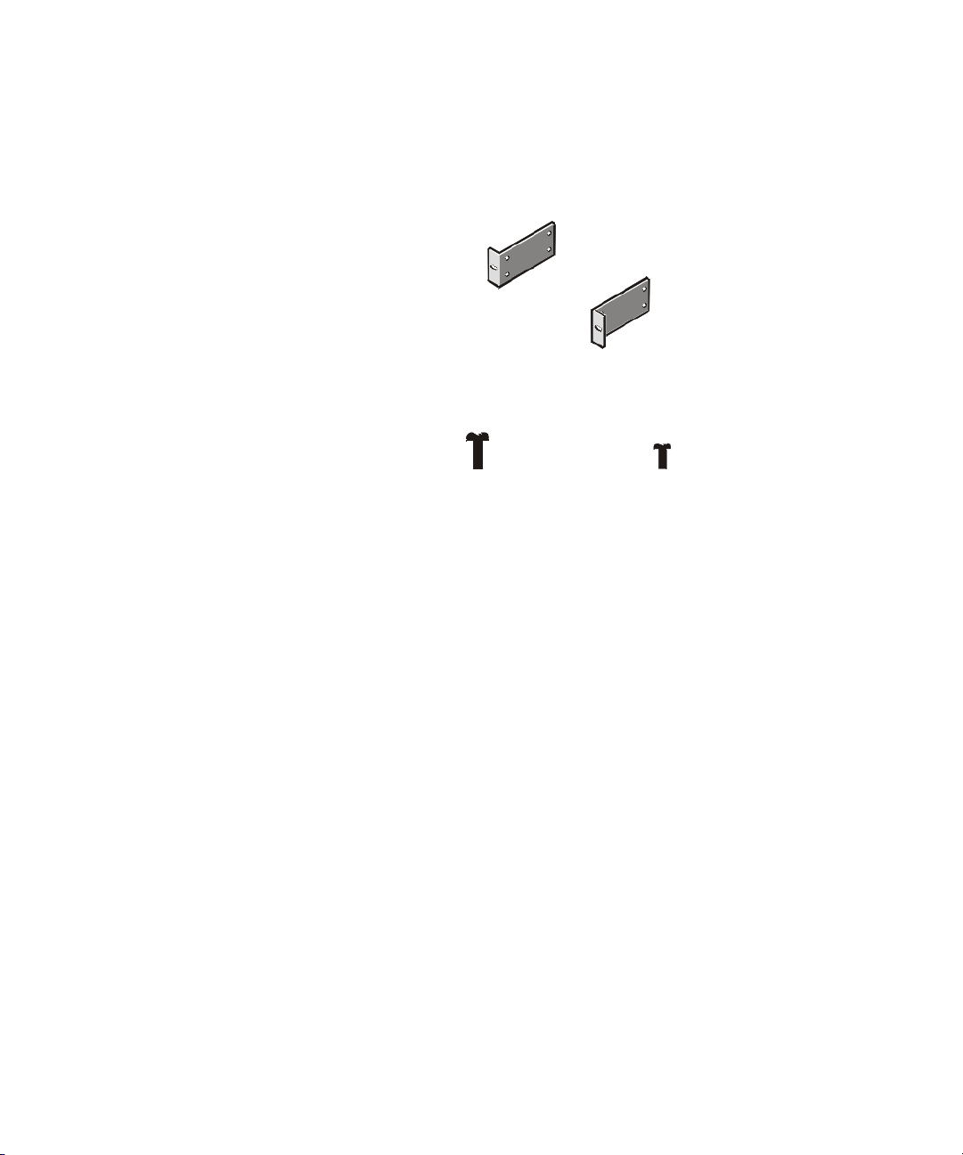
Rack Kit Contents
The rack kit includes the following items (see Figure 1-1):
• Two center-mount brackets
• Four 10-24 x 0.375-inch pan-head Phillips (or slotted) screws
• Two 12-24 x 0.5-inch pan-head Phillips screws
center-mount brackets (2)
12-24 x 0.5-inch pan-head
Phillips screws (2)
Figure 1-1. Two-Post Center-Mount Rack Kit Contents
10-24 x 0.375-inch panhead Phillips screws (4)
Recommended Tools and Supplies
You need the following tools and supplies to install the system in a two-post openframe relay rack:
• #2 Phillips screwdriver
• Masking tape or a felt-tip pen, for use in marking the mounting holes to be used
1-2 Rack Installation Guide
Page 9
Marking the Rack
1. Determine where you want to place the bottom of the system.
CAUTION: If you are installing more than one system, install the first system in the lowest available position in the rack.
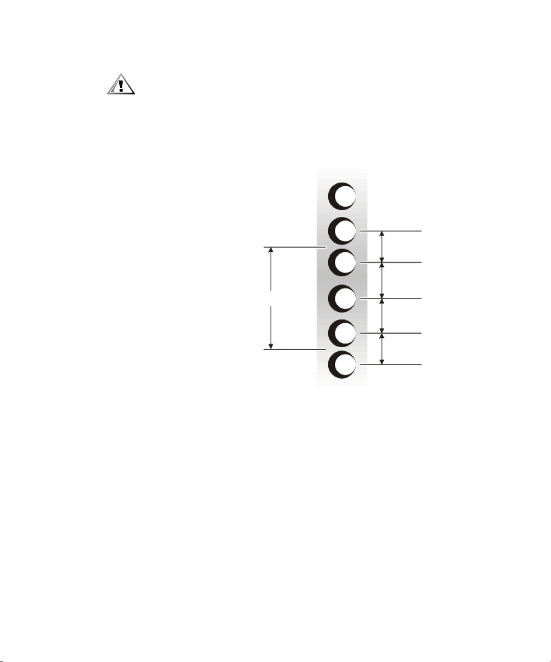
2. Mark the upper and lower-mounting positions on the two posts.
Each 1-U (1.75-inch) vertical space has three holes, with center-to-center spacing
between holes (beginning at the center of the top hole of a 1-U space) of 0.625,
0.625, and 0.5 inch (see Figure 1-2).
0.5 inch
0.625 inch
1.75 inches (1 U)
0.625 inch
0.5 inch
Figure 1-2. Two-Post Open-Frame Relay Rack 1-U Hole Spacing
support.dell.com Rack Installation Guide 1-3
Page 10
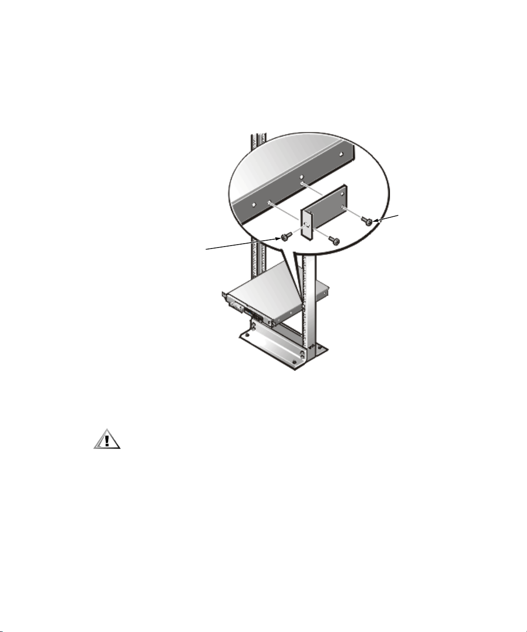
Attaching the Brackets
1. Locate one of the two brackets and align it over the two threaded holes on the
side of the system (see Figure 1-3).
2. Secure the bracket to the system chassis using two 10-24 x 0.375-inch screws
(see Figure 1-3).
Repeat this step to install the remaining bracket on the other side of the system.
10-24 x 0.375-inch
12-24 x 0.5-inch
pan-head
Phillips screws
pan-head Phillips
screws (2 per
bracket)
Figure 1-3. Securing the System in the Rack
Installing the System in the Rack
CAUTION: Due to the size and weight of the system, never attempt to install
the system by yourself.
1. Lift the system into position between the two posts, with the hole in the mount-
2. Secure the system to the rack using a 12-24 x 0.5-inch screw through the mount-
3. Attach the front bezel, if it is not already attached, to the system (see the
1-4 Rack Installation Guide
ing bracket aligned one hole above the mark you made in the two posts.
ing bracket to the front of the left and right posts (see Figure 1-3).
Installation and Troubleshooting Guide for instructions).
This completes the two-post center-mount rack installation.
Page 11

Two-Post Flush-Mount Rack Kit Installation
This procedure provides instructions for installing a Dell system in a two-post openframe relay rack, such as those found in telecommunications equipment facilities.
Both 3-inch and 6-inch wide 2-post racks are accommodated.
The two-post open-frame relay rack must be properly secured to the floor, to the
ceiling or upper wall, and where applicable, to adjacent racks, using floor and wall
fasteners and bracing specified or approved by the rack manufacturer or by industry
standards. Refer to the two-post open-frame relay rack manufacturer’s installation
documentation for precautionary warnings and information before attempting this
installation.
CAUTION: Do not attempt to install the system into a two-post open-frame
relay rack that has not been securely anchored in place. Damage to the
system and personal injury may result.
See “Safety Instructions” found earlier in this guide for additional safety information
regarding rack installation.
Rack Kit Contents
The two-post flush-mount rack kit includes the following items (see Figure 1-4):
• Two flush-mount brackets
• Two inner mounting rails
• Four 12-24 x 0.5-inch pan-head Phillips (or slotted) screws
• Four 10-24 x 0.25-inch flat-head slotted screws for securing the inner mounting
rails to the sides of the system
• One 1-U template
support.dell.com Rack Installation Guide 1-5
Page 12

inner mounting rails (2)
flush-mount brackets (2)
1-U template
Figure 1-4. Two-Post Flush-Mount Rack Kit Contents
Recommended Tools and Supplies
You need the following tools and supplies to install the system in a two-post openframe relay rack:
• #2 Phillips screwdriver
• Masking tape or a felt-tip pen, for use in marking the mounting holes to be used
1-6 Rack Installation Guide
10-24 x 0.25 inch flathead Phillips screws (4)
12-24 x 0.5-inch panhead Phillips screws (4)
Page 13

Marking the Rack
1. Determine where you want to place the bottom of the system.
CAUTION: If you are installing more than one system, install the first system in the lowest available position in the rack.
2. Place the 1-U template over the front of the two-posts of the rack in the desired
location.
3. Position the bottom of the template in line with the desired bottom position of
the system chassis.
4. Mark the upper and lower-mounting positions on the vertical rails as shown by
the V-notches on the sides of the template.
Each 1-U (1.75-inch) vertical space has three holes, with center-to-center spacing
between holes (beginning at the center of the top hole of a 1-U space) of 0.625,
0.625, and 0.5 inch (see Figure 1-5).
0.5 inch
0.625 inch
1.75 inches (1 U)
0.625 inch
0.5 inch
Figure 1-5. Two-Post Open-Frame Relay Rack 1-U Hole Spacing
support.dell.com Rack Installation Guide 1-7
Page 14

Installing the Bracket in the Rack
CAUTION: The 1-U mounting bracket is designed to support a single system. Do not attempt to install any other system in this bracket. Damage to
the system and personal injury may result.
CAUTION: Due to the size and weight of the system, never attempt to install
the system by yourself.
1. Slide the back portion of the bracket to its widest opening and place the mounting bracket into the rack, with the bottom of the bracket at the marks you made
earlier (see Figure 1-6).
2. Slide the back part of the bracket toward the front, with the pins entering the
lower screw holes in the rack, at the marks you made earlier. Secure the bracket
front and back to the rack with a 12-24 x 0.5-inch screw.
Repeat this step to install the remaining bracket on the other side of the rack.
12-24 x 0.5 inch screws (4)
Figure 1-6. Installing the Bracket in the Rack
1-8 Rack Installation Guide
Page 15

Installing the Inner Rails on the System Chassis
1. Locate the two inner rails and position one to the side of the chassis (see
Figure 1-7).
Ensure that the flat end of the inside rail is toward the front of the chassis and
that the end with two threaded holes is located at the back of the chassis. The
flat central part of the inside rail must be facing the chassis, with the raised upper
and lower rail surface facing outward (see Figure 1-7).
Figure 1-7. Securing the Inner Rails to the System Chassis
2. Secure each inner rail to the chassis using two 10-32 x 0.25-inch flat-head screws.
Installing the System in the Rack
CAUTION: Due to the size and weight of the system, never attempt to install
the system by yourself.
1. Remove the optional bezel from the system front panel. Press the tab on each
end of the bezel and pull the bezel straight out from the chassis.
2. Lift the system into position in front of the installed mounting bracket.
support.dell.com Rack Installation Guide 1-9
Page 16

3. Move the system back with its inside rail engaging the mounting bracket. Slide
the system completely into position and secure it to the rack using the captive
fasteners at the outer edge of the front panel (see Figure 1-8).
An internally threaded stud projecting from the front of the tray flanges accepts
the captive fastener on the front of the system.
captive
fasteners
Figure 1-8. Securing the System in the Rack
4. Attach the front bezel, if it was removed in step 1, to the system (see the
Installing Tab Covers
CAUTION: The system’s two-post flush-mount slide assembly does not have
a safety stop. Use care when sliding the system in and out of the rack; the
system could fall out of the rack, possibly resulting in bodily injury and
damage to the system.
1. Push the system completely into the rack.
2. Center the thumbscrew on the tab cover with the clearance hole on the system
1-10 Rack Installa t i o n Gu ide
Installation and Troubleshooting Guide for instructions).
tab, and align the slot on the tab cover with the opening on the system tab (see
Figure 1-9).
Page 17

server tab
thumbscrew
Figure 1-9. Installing the Tab Cover
3. Hold the tab cover firmly onto the server tab and engage the thumbscrew with
the receiving fastener on the slide bracket.
4. Repeat steps 1 through 3 to install the tab cover on the other side of the system.
This completes the two-post flush-mount rack installation.
Four-Post Rack Kit Installation
This procedure provides instructions for installing a Dell system in a four-post rack cabinet. Both 24-U and 42-U racks are accommodated.
Rack Kit Contents
The rack kit includes the following items (see Figure 1-10):
• One pair of slide assemblies
• One cable-management arm
• Four 10-32 x 0.5-inch pan-head Phillips screws
• Six 10-24 x 0.375-inch pan-head Phillips screws
• One 1-U template for a four-post rack
NOTE: If you purchased a Dell rack along with your system, the slide assemblies may
be preinstalled in the rack.
support.dell.com Rack Installation Guide 1-11
Page 18

cable-management arm assembly
slide assemblies with
mounting brackets (1 pair)
1-U template
Figure 1-10. Four-Post Rack Kit Contents
1-12 Rack Installation Guide
10-32 x 0.5-inch
pan-head Phillips
screws (4)
10-24 x 0.375-inch
pan-head Phillips
screws (6)
Page 19

Before You Begin
Before you begin installing your system in the rack, carefully read “Safety Instructions,” found earlier in this guide.
NOTICE: This rack kit is intended to be installed in a Dell rack by trained
service technicians. If you install the kit in any other rack, be sure that the
rack meets the specifications of American National Standards Institute
(ANSI)/Electronic Industries Association (EIA) standard ANSI/EIA-310-D-92,
International Electrotechnical Commission (IEC) 297, and Deutsche Industrie Norm (DIN) 41494. One rack kit is required for each Dell server,
storage system, or appliance that is installed in a rack.
Recommended Tools and Supplies
You need the following tools and supplies to install the system in a four-post rack
cabinet:
• A #2 Phillips screwdriver
• A flat-blade screwdriver
• Masking tape or a felt-tip pen, for use in marking the mounting holes to be used
Installing the Rack Kit
NOTES: If you purchased a Dell rack along with your system, the slide assemblies
may be preinstalled in the rack.
For instructions on installing the system itself, see “Installing the System in the FourPos t Rack” found later in this guide.
To install the slide assemblies in the rack, perform the following steps:
1. Remove the rack’s front and back doors.
2. Install the slide assemblies in the rack.
The subsections that follow include instructions for performing these tasks.
support.dell.com Rack Installation Guide 1-13
Page 20

Removing the Doors From the 42-U Rack
CAUTION: To prevent personal injury due to the size and weight of the
doors, never attempt to remove the doors by yourself.
CAUTION: Store the two doors where they will not injure someone if the
doors accidently fall over.
This procedure provides instructions for removing doors from earlier 42-U Dell racks.
If you have a newer Dell PowerEdge 4210 rack, refer to the procedures contained in
the Dell PowerEdge 4210 Rack Installation Guide.
1. Open the latch on the front door (see Figure 1-11).
Slide the button cover up as far as it will go, press the push button, rotate the
handle clockwise until the latch releases, and then pull the door open.
Figure 1-11. Opening the 42-U Rack Door
push-button
cover
push button
handle
1-14 Rack Installation Guide
Page 21

2. Remove the front door from the rack as shown in Figure 1-12.
a. One person should grasp the top of the door to stabilize it. The other person
should grasp the bottom of the door.
b. The person holding the bottom of the door should press the hinge release
lever on the bottom hinge and then pull the door away from the rack.
c. The person holding the top of the door should press the hinge release lever
on the top hinge and then pull the door away from the rack.
hinge
release
lever
Figure 1-12. Removing the 42-U Rack Doors
3. Repeat steps 1 and 2 to remove the back door from the rack.
support.dell.com Rack Installation Guide 1-15
Page 22

Removing the Doors From the 24-U Rack
CAUTION: To prevent personal injury due to the size and weight of the
doors, never attempt to remove or replace the doors by yourself.
1. Unlock and twist the handle clockwise (see Figure 1-13).
2. Open the front door.
Figure 1-13. Opening the 24-U Rack Door
1-16 Rack Installation Guide
Page 23

3. Remove the front door from the rack as shown in Figure 1-14.
a. With the door open, lift out and fully retract all hinge pins.
b. Once all the hinge pins have been lifted out and retracted, lift the door out.
hinge pin
hinge insert
hinge
Figure 1-14. Removing the 24-U Rack Doors
CAUTION: Store the two doors where they will not injure someone if the
doors accidently fall over.
If you want to reverse the door so that the handle is on the other side, perform the
following steps:
1. With the door open, lift out and fully retract all hinge pins.
2. Remove the hinges and door brackets from the door frame.
3. Replace the hinges and door brackets on the opposite side and switch the position of the handle.
4. Replace the rack door (see the section, “Replacing the Rack Doors,” found later
in this guide).
Installing the Slide Assemblies in the Four-Post Rack
NOTE: If the slide assemblies were preinstalled by Dell, you can skip this section.
support.dell.com Rack Installation Guide 1-17
Page 24

You must allow 1 U (1.75 inches) of vertical space for each system you install in the
rack.
NOTE: The vertical rails of the rack are marked by small indentations in 1-U increments (see Figure 1-15).
1 U (1.75 inches)
Figure 1-15. One Rack Unit
For more information about requirements for installing components in a rack, see
the Dell Rack Advisor software available on the Dell World Wide Web site at
http://support.dell.com.
WARNING: If you are installing more than one system, install the slide
assemblies so that the first system is installed in the lowest available position in the rack.
1-18 Rack Installation Guide
Page 25

To install the slide assemblies in the rack, perform the following steps:
1. Place the front of the template on the vertical rails at the front of the rack where
you want to install the system.
2. Ensure that the printing on the template identifies the side facing outwards as
the template front.
3. Position the bottom of the template in line with the desired bottom position of
the system chassis.
4. Mark the rack’s front vertical rails with a felt-tipped marker or place masking tape
where the system’s upper and lower edges will be located (see Figure 1-16).
5. Make a mark or place tape on the vertical rails next to the template’s V-shaped
notches.
1 U (1.75 inches) between
slide assemblies
(drawing is not to scale)
1-U template
Figure 1-16. Using Template to Mark Vertical Rails
support.dell.com Rack Installation Guide 1-19
Page 26

6. At the front of the rack cabinet, position one of the slide assemblies so that its
mounting-bracket flange fits between the marks or tape you placed on the rack,
marking the upper and lower edges of the template (see Figure 1-17).
The hooks on the bottom of the mounting bracket should enter the holes beside
the lower marks you made in the vertical rails.
7. Secure the front of the mounting-bracket flange with a 10-32 x 0.5-inch pan-head
Phillips screw in the front vertical rail (see Figure 1-17).
8. Push back on the back mounting-bracket flange until the mounting hook locks into
the matching square hole on the back vertical rail.
9. Repeat steps 6 through 8 for the remaining slide assembly on the other side of
the rack.
10-32 x 0.5-inch
pan-head Phillips
screw (2 per slide
assembly)
mounting-bracket
flange
Figure 1-17. Installing the Slide Assemblies
1-20 Rack Installation Guide
front of rack
slide assemblies (2)
Page 27

Installing the Inner Rails on the System Chassis
To install the inner rails to the sides of the system, perform the following steps.
CAUTION: The system may weigh up to 10 kilograms (23 pounds) when
fully loaded. To prevent personal injury, do not attempt to move the system
by yourself.
1. Place the system on its side (see Figure 1-18) on a piece of foam or cardboard (to
prevent damage to the system) while you install the inner rails to the sides of the
system.
inner rail (2)
10-24 x 0.375-inch panhead Phillips screws (6)
Figure 1-18. Installing the Inner Rails
2. Secure each inner rail to the side of the chassis with three 10-24 x 0.375-inch panhead Phillips screws (see Figure 1-18).
Installing the System in the Four-Post Rack
WARNING: If you are installing more than one system, install the first system in the lowest available position in the rack.
WARNING: Never pull more than one component out of the rack at a time.
1. Pull the two interior slide assemblies out of the rack until they lock in the
extended position.
CAUTION: Because of the size and weight of the system, never attempt to
install the system in the slide assemblies by yourself.
2. Lift the system into position in front of the extended slides.
Grasp the system with one hand on the right side of the system and the other
hand on the left side of the system.
support.dell.com Rack Installation Guide 1-21
Page 28

3. Align the inner rails you installed on the sides of the system with the open portion of the slide assemblies (see Figure 1-19).
4. Push the system into the slide assemblies until the system stops (see
Figure 1-19).
inner rail
captive thumbscrews (2)
Figure 1-19. Installing the System in the Rack
5. Press in on the release latch on each extended slide and push the chassis into the
6. Tighten the captive thumbscrews on each side of the front chassis panel to
Installing the Cable-Management Arm
To install the cable-management arm on the back of the system, perform the following steps:
1. Facing the back of the rack cabinet, locate the threaded hole on the back of the
1-22 Rack Installation Guide
rack.
secure the system to the rack.
slide assembly and secure the end of the cable-management arm (the end having
a bracket and captive thumbscrew) to the right side vertical rail (see Figure 1-20).
The bracket snaps into the square mounting holes on the vertical rail and is
secured with a captive thumbscrew.
Page 29

pin
captive
fastener
Figure 1-20. Installing the Cable-Management Arm
2. Align the free end of the cable-management arm (the end with the pin and captive thumbscrew) to the back end of the right (or left) side inner rail (as viewed
from the back) of the system.
3. Secure the cable-management arm to the inner rail with the captive thumbscrew
(see Figure 1-20).
4. Attach the input/output (I/O) cables to their respective expansion cards on the
back of the system.
5. Connect the remaining cables to the system.
For details, see your system’s Installation and Troubleshooting Guide and User’s
Guide.
6. Secure the cables to the cable-management arm:
a. After connecting the cables to the system, unscrew the thumbscrews that
secure the front of the server to the front vertical rail.
b. Slide the system forward to the fully extended position.
c. Route the cables along the cable-management arm, allowing some additional
cable slack at the hinge positions, and secure the cables to the cablemanagement arm with the Velcro straps attached to the cable-management
arm.
support.dell.com Rack Installation Guide 1-23
Page 30

7. Slide the system in and out of the rack to verify that the cables are routed
correctly and do not bind, stretch, or pinch with the movement of the cablemanagement arm.
NOTE: As you pull the system out to its furthest extension, the slide assemblies
will lock in the extended position. To push the system back into the rack, press
the locking latch on the side of the slide to release the locks, and then slide the
system completely into the rack.
Replacing the Rack Doors
The following subsections describe procedures for replacing the rack doors on earlier
Dell 42-U and 24-U racks. If you have a Dell PowerEdge 4210 rack, see the procedures
contained in the Dell PowerEdge 4210 Rack Installation Guide.
Replacing the Rack Doors on a 42-U Rack
CAUTION: To prevent personal injury due to the size and weight of the
doors, never attempt to remove or replace the doors by yourself.
1. Lift the front door into position and align the hinges with the holes in the rack as
shown in Figure 1-12.
2. Slide the hinges into the holes in the rack until the hinge release levers lock the
hinges into position.
3. Close the door latch by rotating the handle counterclockwise until it stops, push
in the handle until it locks in position, and then slide the button cover down over
the push button (see Figure 1-11).
4. Repeat steps 1 through 3 to install the back door.
Replacing the Rack Doors on a 24-U Rack
CAUTION: To prevent personal injury due to the size and weight of the
doors, never attempt to remove or replace the doors by yourself.
1. Lift the front door into position and align the hinges with the holes in the rack
2. Line up the door hinges and then press them down.
3. Close the door latch by rotating the handle counterclockwise until it stops, and
4. Repeat steps 1 through 3 to install the back door.
1-24 Rack Installation Guide
(see Figure 1-14).
then push the handle in until it locks in position (see Figure 1-13).
This completes the four-post rack kit installation.
Page 31

Index
A
attaching inner rails
two-post flush-mount kit
attaching the brackets
two-post center-mount kit, 1-4
two-post flush-mount kit
, 1-9
, 1-8
C
cable-management arm installation
four-post rack
cables
routing
cautions
contents illustrated
contents listed
, v
four-post kit, 1-12
two-post center-mount kit
two-post flush-mount kit
four-post kit
two-post center-mount kit
two-post flush-mount kit
, 1-22
, 1-23
, 1-2
, 1-6
, 1-11
, 1-2
, 1-5
D
Dell Web site, 1-18
doors
removing
24-U
, 1-16
42-U
, 1-15
replacing
24-U rack
42-U rack
, 1-24
, 1-24
F
four-post Dell rack installation, 1-11
H
hole spacing
two-post rack kit
, 1-3
I
inner rails
installing
installation
four-post rack kit
two-post center-mount kit
two-post flush-mount kit
, 1-9, 1-21
, 1-11
, 1-1
, 1-5
support.dell.com Rack Installation Guide 1
Page 32

installing in four-post rack
cable-management arm
slide assemblies
installing slide assemblies
four-post rack
installing the brackets
two-post rack kit, 1-8
installing the system
four-post rack
two-post center-mount rack
two-post flush-mount rack
, 1-20
, 1-17
, 1-21
K
kit contents
four-post rack
two-post center-mount rack
two-post flush-mount rack
, 1-11
M
marking the rack
four-post rack
two-post center-mount rack
two-post flush-mount rack
marking the vertical rails
four-post rack
, 1-19
, 1-19
, 1-23
, 1-9
, 1-5
, 1-7
, 1-4
, 1-2
, 1-3
R
rack-mount precautions, 1-4, 1-5, 1-13
routing cables
, 1-23
S
system
installing in four-post rack
installing in two-post center-mount
rack, 1-4
installing in two-post flush-mount rack
1-9
weight
, 1-21
, 1-22
T
tab covers
installing
template
four-post rack
two-post flush-mount
tools and supplies
four-post kit
two-post center-mount kit
two-post flush-mount kit
two-post center-mount kit installation
two-post flush-mount installation
, 1-10
, 1-12
, 1-6
, 1-13
, 1-2
, 1-6
1-1
, 1-5
,
,
N
notational conventions, v
notes
P
PowerEdge 4210 rack, 1-14, 1-24
2 Rack Installation Guide
, v
V
vertical rails
marking
W
warnings, v
, 1-19
 Loading...