

Page 1
T5, T14D, T20C, T24C, T40
Blast Chiller/Shock Freezers
Service, Installation and Care Manual
Please read this manual completely before attempting to install or operate this equipment! Notify carrier of
damage! Inspect all components immediately. See page 2.
Blast Chillers/Shock Freezers
IMPORTANT INFORMATION
READ BEFORE USE
PLEASE SAVE THESE INSTRUCTIONS!
Effective Date August 2006
Page 2

CONTENTS
1. GENERAL DOCUMENTATION
1.1 General information page 5
1.2 Installation page 5
1.3 Transport and handling page 5
1.4 Unpacking - disposal of packaging materials page 5
1.5 General safety regulations page 6
2. INSTALLATION
2.1 Data plate information page 6
2.2 Positioning page 6
2.3 Ambient temperature and air circulation page 7
2.4 Electrical connections page 7
2.5 Refrigeration component connections - remote assemblies page 7
2.6 Condensate drainage connection page 7
2.7 Information for the installation technician page 8
2.8 Safety and control systems page 8
2.9 Appliance disposal page 8
3. ADVICE TO ENSURE EFFICIENT APPLIANCE OPERATION
3.1 Shut-down procedures page 9
3.2 Operating tips page 9
3.2.1 Precooling page 9
3.2.2 Loading the appliance page 9
4. DESCRIPTION OF THE CONTROL PANEL page 10
4.1 Push-buttons page 11
5. PROGRAMMING AND OPERATING INSTRUCTIONS
5.1 Starting up the appliance page 12
5.2 Soft blast chilling by temperature page 13
5.3 Soft timed blast chilling page 14
Hard blast chilling page 14
5.4 Hard blast chilling by temperature page 15
5.5 Hard timed blast chilling page 16
5.6 Blast freezing by temperature page 17
5.7 Timed blast freezing page 18
Page 3

6. APPLIANCE FUNCTIONS
6.1 Date and time settings page 19
6.2 Ice cream surface hardening page 19
6.3 Muting the beeper and alarm reset page 19
6.4 Program storage page 19
6.5 Displaying the three latest HACCP alarms page 20
6.6 Printing out stored data page 20
6.7 Forced ventilation function page 20
6.8 User programming page 20
6.9 Manual defrosting page 20
6.10 Automatic defrost cycles page 20
7. ALARM MANAGEMENT
7.1 Storage of data/errors page 22
7.2 Alarms list page 22
8. MAINTENANCE AND CLEANING
8.1 General safety regulations page 27
8.2 Cleaning the condenser page 27
8.3 Cleaning the cell page 28
8.4 Defrost water drainage page 28
Page 4
1. GENERAL DOCUMENTATION
1.1. General information
• This manual is an integral part of the product,
providing all the information required to ensure
correct installation, operation and maintenance
of the machine.
• Read the manual carefully, making reference
to it for machine operation. Keep the manual
in a safe place where it can be accessed by all
authorised operators (installers, operators and
service personnel).
• The machine has been designed for professional
applications only and should only be operated
by qualied personnel.
• The machine must only be used for the purposes
for which it was designed, i.e. for chilling and
freezing food products.
The machine must not be used for products
requiring constant temperature control and
recording, such as:
- heat-sensitive chemicals,
- medicines or
- blood products.
• The manufacturer declines all responsibility
for any damage caused by incorrect or
unreasonable machine use, such as:
• improper use by untrained persons;
• technical modications or operations not suited
to specic models;
• use of non-original or non-specic spare parts;
• failure to follow the instructions given in this
manual.
1.2 Installation
In the event that the machine is tted with
a remote condenser unit, the installation
technician is responsible for checking all
connections in compliance with the instructions
given by Deleld for plant and machine
installation.
1.3 Transport and handling
• To load or unload the machine and/or
components from/onto the means of transport,
use a lift truck or fork lift equipped with forks
that are at least half the length of the machine
housing; use a crane if the machine is tted with
eye bolts. Select the lifting equipment suited
to the weight and overall dimensions of the
packaged machine/components.
• When handling the machine/ components,
apply all precautions to prevent damage, in
compliance with the information given on the
packaging material
1.4 Unpacking
• Remove all cardboard, wood or other materials
from the wood base on which the machine is
set. Lift the machine/components with suitable
means (e.g. lift truck), remove the wood base,
then position the machine/components in the
allocated site.
• Once all packing material has been removed,
check that the machine has not been damaged
in any way.
• Remove the protective
PVC lm on the stainless
steel panels from all
internal and external
surfaces (g. 2).
• Always wear protective
gloves when handling
packing material and the
wood base.
• NB Dispose of packing materials in compliance
with disposal regulations applied in the country
where the machine is to be installed. Never
dispose of materials in the environment.
1.5 General safety regulations
Failure to observe the recommendations made
by the present manual will be at the entire
responsibility of the machine user. The main
safety regulations are as follows:
- do not touch the machine with moist or wet
hands or feet;
- never operate the machine while barefoot;
- do not insert screwdrivers, cooking utensils
or any other object between the guards and
moving parts;
- before performing cleaning or routine
maintenance operations, disconnect the
machine from the power supply at the
master switch and the main knife switch (if
present);
- never pull on the power cable to disconnect
the machine from the power supply.
Page 5
2. INSTALLATION
2.1 Data plate information
• Check that the data specied on the plate
correspond to the characteristics of the power
supply (V, kW, Hz, no. phases and power
available).
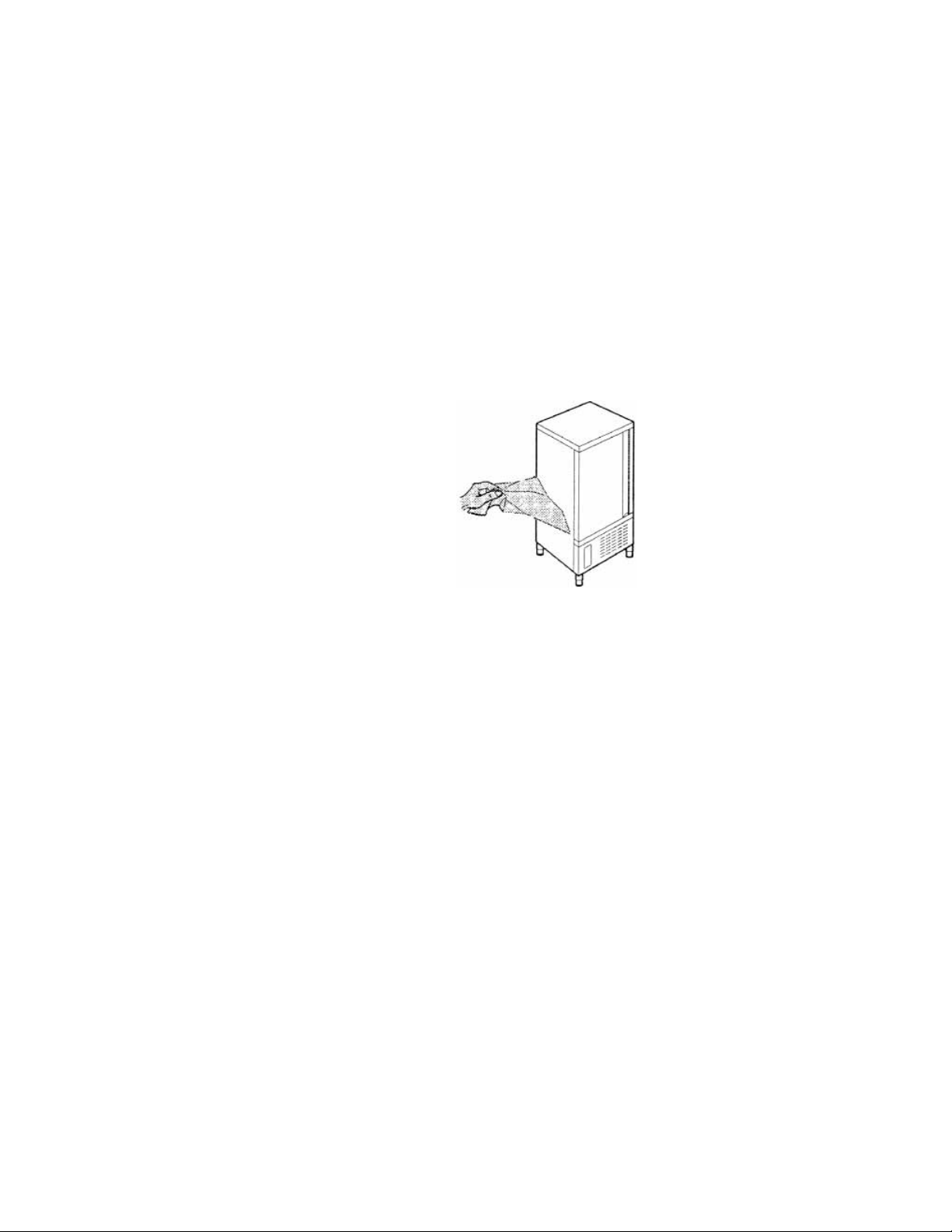
• The dataplate with appliance specications
is located at the rear exterior of the machine
and/or on the electrical
boards (g. 3). The setup of individual units
and the installation of
condensers are subject to
the re-safety regulations
of the country in which the machine is installed;
seek all necessary advice from the local reghting authorities. Bear in mind that the
intervention of safety valves or plug fuses in the
refrigerating circuit will lead to the immediate
discharge of refrigerant into the environment.
2.2 Positioning
• The machine must be installed in complete
compliance with safety regulations, procedures
and standing laws.
• Position the machine in the allocated site.
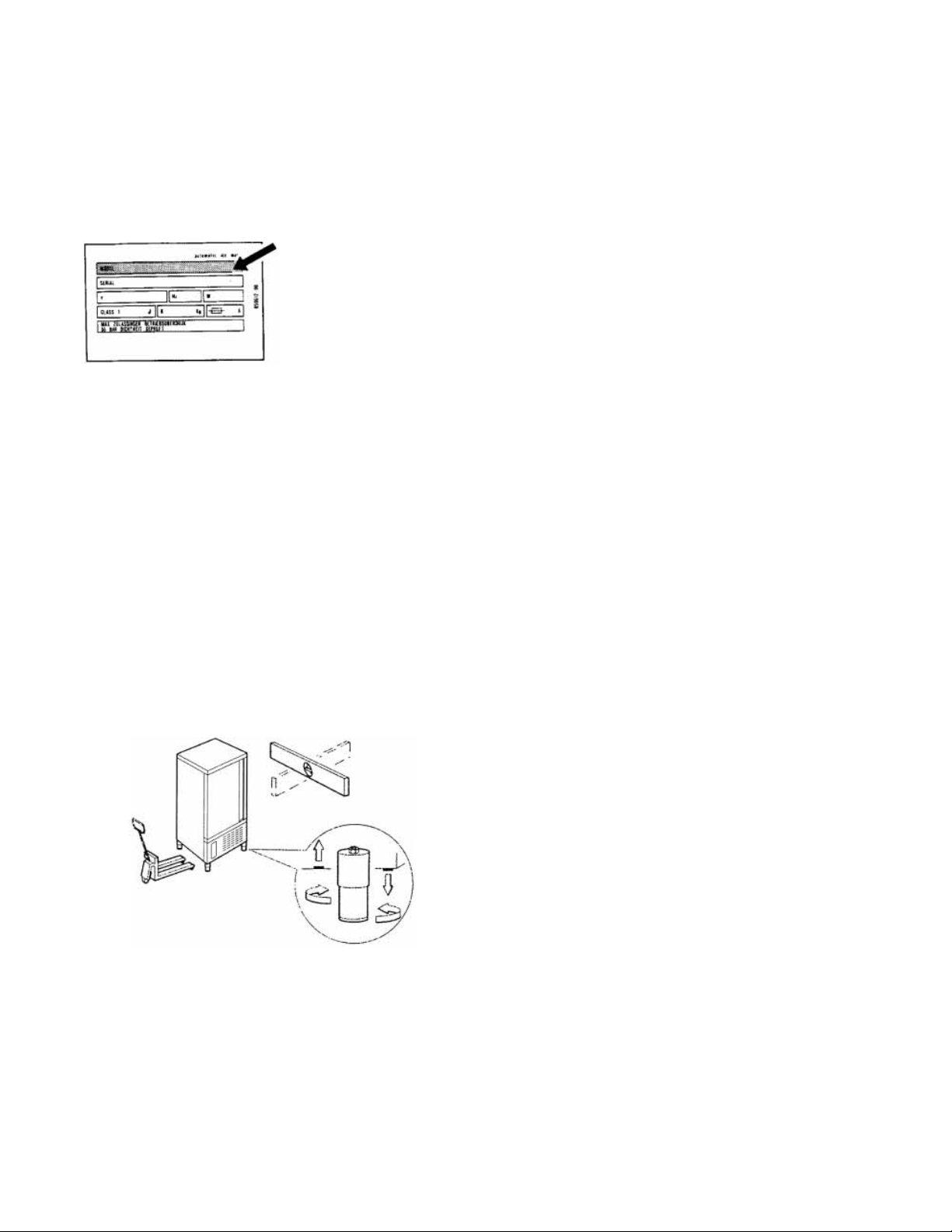
• Adjust the machine feet by turning the foot
clockwise until the appliance is perfectly level.
In the case of particularly heavy equipment, use
appropriate lifting means.
(g. 4).
• If the appliance is not perfectly level, correct
operation and condensate ow-o will not be
assured.
AVOID
• direct exposure to sunlight;
• closed sites with high temperatures and poor air
circulation;
• installing the machine near sources of heat
Installation Clearance Requirements
All Cabinets:
12” clearance above top
12” clearance on sides and rear
Remote condensing units for T20, T24 and T40
models.
24” clearance above top
6” clearance on sides and rear
2.3 Ambient temperature and air circulation
For air-cooled appliances, the maximum ambient
temperature for operation is 90°F / 32°C. Correct
operation cannot be guaranteed at higher
temperatures. The machine may operate safely
to a maximum temperature of 100°F / 38°C.
Remote condensing units may be installed
indoors next to the unit or within 25 ft. Consult
Deleld if placementwill be greater than 25
ft. away. Remote condensing units may also
be installed outdoors but require a U.L. listed
enclosure which is supplied as an option from
Deleld. Sucient air circulation must be
guaranteed at all times.
2.4 Electrical connections
A dedicated thermal-magnetic circuit breaker
compliant with established regulations must be
installed on the appliance power line.
• Connected electrical cables must correspond
to the technical data (as specied on electrical
drawings provided by the installation
technician).
Connect the earthing conductor to an ecient
earthing system.
THE MANUFACTURER DECLINES ALL LIABILITY
AND GUARANTEE OBLIGATIONS IN THE EVENT
OF INJURY TO PERSONS OR DAMAGE TO
EQUIPMENT AND OBJECTS DUE TO INCORRECT
INSTALLATION AND/OR FAILURE TO COMPLY
WITH STANDING INSTALLATION REGULATIONS.
Page 6

2.6 Condensate drainage connection
For models T20C-T24C-T40 t a condensate
water drainage hose with a minimum diameter
of 1” . Provide a waste pipe with a trap with a
diameter of at least 1 1/2” at oor level.
2.7 Information for the installation technician
Before starting up the machine, check that it has
been correctly installed.
1. Check that there are no gas leaks from weldings
or joints made during installation works.
2. Check that the pipes connecting the condenser
to the remote condensing unit have been well
insulated.
3. Check all wiring connections.
4. Check electrical input.
5. Check the standard pressure in the refrigerant
system.
6. Perform at least one blast freezing cycle (to the
SET temperature) and one manual defrosting
cycle. In the event that the appliance or
the remote condensing unit have not been
transported in a vertical position (e.g. on
the back) or have been overturned during
installation works, allow at least 4 hours before
starting up the equipment.
2.8 Safety and control systems
• Door microswitch: shuts down fan operation in
the cell when the door is opened.
• General fuses: protect the power circuit against
short circuiting and overloads.
• Compressor heat relay: intervenes in the event
of overloads or operating faults.
• Safety pressure switch: intervenes in the event of
excessive pressure in the refrigerant circuit.
• Plug fuses: intervene in the event of verpressure
or operating fault in the safety pressure switch
(see above).
• Chamber temperature control: operated by the
electronic board by means of a probe inside the
cell.
• Temperature control end defrost cycle:
controlled by the electronic board by means of
the probe in the evaporator.
2.9 Appliance disposal
After the useful life of the applicance has been
realized, be sure to demolish and dispose of the
machine in compliance with the regulations
applied in the country of installation,
particularly in regards to refrigerant gas and
compressor lubricant oil.
Page 7
3. ADVICE TO ENSURE EFFICIENT APPLIANCE OPERATION
3.1 Shut-down procedures
In the event of emergency, shut down the
appliance by switching o power at the
main panel, by means of a breaker or power
disconnect or by removing the plug from the
power socket.
3.2 Operating tips
Before starting up the appliance, clean the
inside of the compartment thoroughly.
3.2.1 Pre-cooling
Before using the appliance for the rst time,
or after a prolonged period of disuse, precool
the compartment by running an empty cycle
until the set operating temperature has been
reached.
To ensure optimal performance without any
alteration to food quality: arrange food products
in such a way as to favour the circulation of cold
air throughout the compartment; open the door
as little as possible.
3.2.2 Loading the appliance
a) Ensure that foods to be chilled and/or frozen
are separate and do not have a thickness greater
than 2’’/50mm-3’’/80mm. Do not load the
appliance beyond the quantity recommended
by the manufacturer.
c) Position trays inside the tray compartment as
far as they will go, as close as possible to the
evaporator.
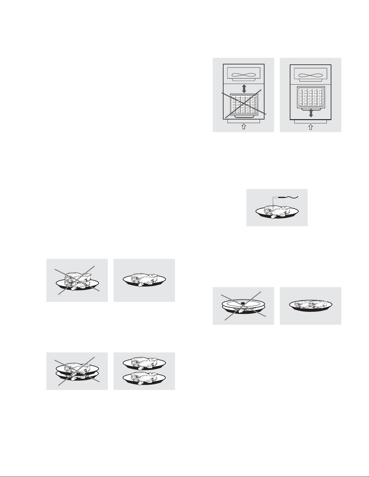
d) Position the core probe at the centre of the
largest product or food item; make sure that the
tip of the probe does not protrude or touch the
tray. The probe must be cleaned and sanitised
before each new cycle (operation) to prevent
inadvertent contamination.
e) Avoid covering the trays and/or containers with
insulating covers or lm. The more the product
is insulated, the more time is required for
chilling or freezing. Trays should be packaged
when the product has been chilled, before
being placed in storage.
b) Ensure that there is sucient clearance
between trays to enable free air circulation. If
the appliance is not completely full, distribute
the trays and foods evenly throughout the
available space.
Page 8
+38o
0o
+38o
HARD
oC
HACCP PROGRAM
6
5
15
1
12
10
3
5a
4
5b
14
7
8
9
11
2
13
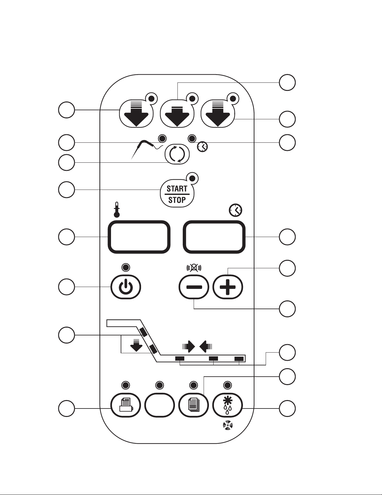
4. DESCRIPTION OF THE VERTICAL CONTROL PANEL
Page 9
4.1
PUSH-BUTTONS
:
1.
ON /OFF (STAND BY)
2.
SOFT BLAST CHILLING CYCLE (+38°F / +3°C)
3.
HARD BLAST CHILLING CYCLE (+38°F / +3°C)
4.
BLAST FREEZING CYCLE (0°F / -18°C)
5.
END CYCLE BY TIME / PROBE (TEMPERATURE)
5A.
PROBE CHILLING INDICATOR LED
5B.
TIMED CHILLING INDICATOR LED
6.
CYCLE START / STOP
7.
INCREASE VALUE
8.
DECREASE VALUE
9.
RECIPE PROGRAMS (CHILLING CYCLES)
10.
HACCP AND PRINTER (OPTIONAL)
11.
DEFROSTING / FORCED VENTILATION
12.
CHILLING / FREEZING CYCLE INDICATOR LED
13.
STORAGE INDICATOR LED
14.
TIME DISPLAY
15.
TEMPERATURE DISPLAY
oC
HACCP
PROGRAM
0o
+38o
HARD
+38o
Page 10
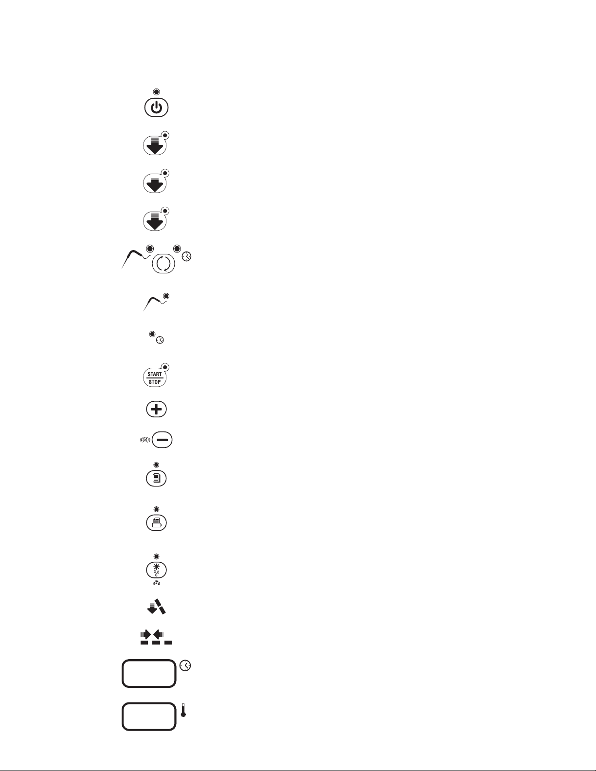
PUSH-BUTTONS
:
ON /OFF (STAND BY)
SOFT BLAST CHILLING CYCLE (+38°F / +3°C)
HARD BLAST CHILLING CYCLE (+38°F / +3°C)
BLAST FREEZING CYCLE (0°F / -18°C)
END CYCLE BY TIME / PROBE (TEMPERATURE)
PROBE CHILLING INDICATOR LED
TIMED CHILLING INDICATOR LED
CYCLE START / STOP
INCREASE VALUE
DECREASE VALUE
RECIPE PROGRAMS (CHILLING CYCLES)
HACCP AND PRINTER (OPTIONAL)
DEFROSTING / FORCED VENTILATION
CHILLING / FREEZING CYCLE INDICATOR LED
STORAGE INDICATOR LED
TIME DISPLAY
HACCP
PROGRAM
0o
+38o
HARD
+38o
PUSH-BUTTONS
:
ON /OFF (STAND BY)
SOFT BLAST CHILLING CYCLE (+38°F / +3°C)
HARD BLAST CHILLING CYCLE (+38°F / +3°C)
BLAST FREEZING CYCLE (0°F / -18°C)
END CYCLE BY TIME / PROBE (TEMPERATURE)
PROBE CHILLING INDICATOR LED
TIMED CHILLING INDICATOR LED
CYCLE START / STOP
INCREASE VALUE
DECREASE VALUE
RECIPE PROGRAMS (CHILLING CYCLES)
HACCP AND PRINTER (OPTIONAL)
DEFROSTING / FORCED VENTILATION
CHILLING / FREEZING CYCLE INDICATOR LED
STORAGE INDICATOR LED
TIME DISPLAY
TEMPERATURE DISPLAY
oC
HACCP
PROGRAM
0o
+38o
HARD
+38o
PUSH-BUTTONS
:
ON /OFF (STAND BY)
SOFT BLAST CHILLING CYCLE (+38°F / +3°C)
HARD BLAST CHILLING CYCLE (+38°F / +3°C)
BLAST FREEZING CYCLE (0°F / -18°C)
END CYCLE BY TIME / PROBE (TEMPERATURE)
PROBE CHILLING INDICATOR LED
0o
+38o
HARD
+38o
PUSH-BUTTONS
:
ON /OFF (STAND BY)
SOFT BLAST CHILLING CYCLE (+38°F / +3°C)
HARD BLAST CHILLING CYCLE (+38°F / +3°C)
BLAST FREEZING CYCLE (0°F / -18°C)
END CYCLE BY TIME / PROBE (TEMPERATURE)
0o
+38o
HARD
+38o
PUSH-BUTTONS
:
ON /OFF (STAND BY)
PUSH-BUTTONS
:
ON /OFF (STAND BY)
PUSH-BUTTONS
:
ON /OFF (STAND BY)
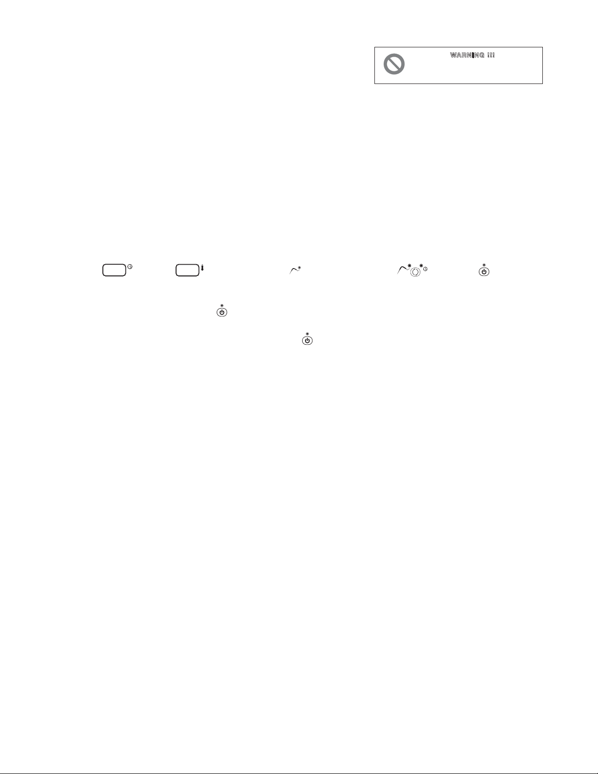
5. PROGRAMMING AND OPERATING INSTRUCTIONS
GB
WWAARRNNIINNGG!!!!!
!
THESE OPERATIONS MUST BE PERFORMED
BY A CERTIFIED INSTALLATION
TECHNICIAN ONLY.
5.1 STARTING UP THE APPLIANCE (only for T14D / T20C / T24C / T40)
PRE HEATING FUNCTION OF COMPRESSOR SUP
When power is initially supplied to the cabinet, a 2-hour pre-heating phase starts and the display shows
some blinking dashes “---”. During this phase the machine cannot be started. This important information is
shown on a yellow label placed inside the door.
Initial pre-heating is necessary in order to safeguard the compressor’s life. Only if strictly necessary (and
under the customer’s responsibility) it is possible to by-pass countdown by pressing push button “Printer/
HACCP” for about 5 seconds.
This function is not activated if machine stops/starts operating due to lack of power during working cycle.
When the appliance is powered up, it can be:
• ON displays 15 and 16 and left LED 5A on push-button 5 on, LED 1
o
• OFF-STAND-BY LED on push-button 1 on
To switch from one status to another, press push-button 1 .
Whenever the appliance switches from STAND-BY status to ON, a self-test is carried out: all LEDs and displays
are switched on, push-buttons are checked, then the installed software version is displayed.
OPERATION
The main work cycles (chilling/freezing) performed by the appliance:
• SOFT BLAST CHILLING (+38°F / +3°C)
Pre-cooked food is rapidly chilled (90’) to a temperature of +38°F / +3°C, thus preventing proliferation
of bacteria and preventing dehydration of the cooked food due to evaporation. Food can
thus be stored perfectly for 5 to 7 days without altering its original qualities. The soft cycle is recommended
for delicate, thin foods such as rice, vegetables and fried foods.
• HARD BLAST CHILLING (+38°F / +3°C)
This process is designed to cool food products with a thickness greater than 2-3 cm/1’’ and is very eective
for dense, greasy or large-sized foods. Variable air temperatures are used to accelerate penetration of cold
into the product.
• BLAST FREEZING (0°F / -18°C)
This function freezes the product completely to a temperature of 0°F / -18°C in approximately 4 hours.
The rapidity of the process prevents formation of macrocrystals essential to ensure that the product
retains its original consistency and quality when thawed for consumption.
• AUTOMATIC CONSERVATION
At the end of each cycle (chilling or freezing), the appliance will automatically switch to the
required storage temperature.
Two dierent end-cycle modes are available for each cycle:
• BY TEMPERATURE - the cycle ends when the probe reaches the required temperature.
• TIMED - cycle length is pre-set
Page 11

IMPORTANT: work cycles and modes can only be selected when the appliance is ON (LED on push -
PUSH-BUTTONS
:
ON /OFF (STAND BY)
SOFT BLAST CHILLING CYCLE (+38°F / +3°C)
HARD BLAST CHILLING CYCLE (+38°F / +3°C)
BLAST FREEZING CYCLE (0°F / -18°C)
END CYCLE BY TIME / PROBE (TEMPERATURE)
PROBE CHILLING INDICATOR LED
TIMED CHILLING INDICATOR LED
CYCLE START / STOP
0o
+38o
HARD
+38o
PUSH-BUTTONS
:
ON /OFF (STAND BY)
SOFT BLAST CHILLING CYCLE (+38°F / +3°C)
+38o
PUSH-BUTTONS
:
ON /OFF (STAND BY)
SOFT BLAST CHILLING CYCLE (+38°F / +3°C)
HARD BLAST CHILLING CYCLE (+38°F / +3°C)
BLAST FREEZING CYCLE (0°F / -18°C)
END CYCLE BY TIME / PROBE (TEMPERATURE)
0o
+38o
HARD
+38o
PUSH-BUTTONS
:
ON /OFF (STAND BY)
SOFT BLAST CHILLING CYCLE (+38°F / +3°C)
HARD BLAST CHILLING CYCLE (+38°F / +3°C)
BLAST FREEZING CYCLE (0°F / -18°C)
END CYCLE BY TIME / PROBE (TEMPERATURE)
PROBE CHILLING INDICATOR LED
0o
+38o
HARD
+38o
PUSH-BUTTONS
:
ON /OFF (STAND BY)
SOFT BLAST CHILLING CYCLE (+38°F / +3°C)
HARD BLAST CHILLING CYCLE (+38°F / +3°C)
BLAST FREEZING CYCLE (0°F / -18°C)
END CYCLE BY TIME / PROBE (TEMPERATURE)
PROBE CHILLING INDICATOR LED
TIMED CHILLING INDICATOR LED
CYCLE START / STOP
0o
+38o
HARD
+38o
PUSH-BUTTONS
:
ON /OFF (STAND BY)
SOFT BLAST CHILLING CYCLE (+38°F / +3°C)
HARD BLAST CHILLING CYCLE (+38°F / +3°C)
BLAST FREEZING CYCLE (0°F / -18°C)
END CYCLE BY TIME / PROBE (TEMPERATURE)
PROBE CHILLING INDICATOR LED
0o
+38o
HARD
+38o
PUSH-BUTTONS
:
ON /OFF (STAND BY)
SOFT BLAST CHILLING CYCLE (+38°F / +3°C)
HARD BLAST CHILLING CYCLE (+38°F / +3°C)
BLAST FREEZING CYCLE (0°F / -18°C)
END CYCLE BY TIME / PROBE (TEMPERATURE)
PROBE CHILLING INDICATOR LED
TIMED CHILLING INDICATOR LED
CYCLE START / STOP
INCREASE VALUE
DECREASE VALUE
RECIPE PROGRAMS (CHILLING CYCLES)
HACCP AND PRINTER (OPTIONAL)
DEFROSTING / FORCED VENTILATION
CHILLING / FREEZING CYCLE INDICATOR LED
HACCP
PROGRAM
0o
+38o
HARD
+38o
PUSH-BUTTONS
:
ON /OFF (STAND BY)
SOFT BLAST CHILLING CYCLE (+38°F / +3°C)
HARD BLAST CHILLING CYCLE (+38°F / +3°C)
BLAST FREEZING CYCLE (0°F / -18°C)
END CYCLE BY TIME / PROBE (TEMPERATURE)
PROBE CHILLING INDICATOR LED
TIMED CHILLING INDICATOR LED
CYCLE START / STOP
INCREASE VALUE
DECREASE VALUE
RECIPE PROGRAMS (CHILLING CYCLES)
HACCP AND PRINTER (OPTIONAL)
DEFROSTING / FORCED VENTILATION
CHILLING / FREEZING CYCLE INDICATOR LED
STORAGE INDICATOR LED
TIME DISPLAY
TEMPERATURE DISPLAY
oC
HACCP
PROGRAM
0o
+38o
HARD
+38o
PUSH-BUTTONS
:
ON /OFF (STAND BY)
SOFT BLAST CHILLING CYCLE (+38°F / +3°C)
HARD BLAST CHILLING CYCLE (+38°F / +3°C)
BLAST FREEZING CYCLE (0°F / -18°C)
END CYCLE BY TIME / PROBE (TEMPERATURE)
PROBE CHILLING INDICATOR LED
TIMED CHILLING INDICATOR LED
CYCLE START / STOP
INCREASE VALUE
DECREASE VALUE
RECIPE PROGRAMS (CHILLING CYCLES)
HACCP AND PRINTER (OPTIONAL)
DEFROSTING / FORCED VENTILATION
CHILLING / FREEZING CYCLE INDICATOR LED
STORAGE INDICATOR LED
TIME DISPLAY
HACCP
PROGRAM
0o
+38o
HARD
+38o
PUSH-BUTTONS
:
ON /OFF (STAND BY)
SOFT BLAST CHILLING CYCLE (+38°F / +3°C)
HARD BLAST CHILLING CYCLE (+38°F / +3°C)
BLAST FREEZING CYCLE (0°F / -18°C)
END CYCLE BY TIME / PROBE (TEMPERATURE)
PROBE CHILLING INDICATOR LED
TIMED CHILLING INDICATOR LED
CYCLE START / STOP
INCREASE VALUE
DECREASE VALUE
RECIPE PROGRAMS (CHILLING CYCLES)
HACCP AND PRINTER (OPTIONAL)
DEFROSTING / FORCED VENTILATION
CHILLING / FREEZING CYCLE INDICATOR LED
STORAGE INDICATOR LED
TIME DISPLAY
HACCP
PROGRAM
0o
+38o
HARD
+38o
PUSH-BUTTONS
:
ON /OFF (STAND BY)
SOFT BLAST CHILLING CYCLE (+38°F / +3°C)
HARD BLAST CHILLING CYCLE (+38°F / +3°C)
BLAST FREEZING CYCLE (0°F / -18°C)
END CYCLE BY TIME / PROBE (TEMPERATURE)
PROBE CHILLING INDICATOR LED
TIMED CHILLING INDICATOR LED
CYCLE START / STOP
INCREASE VALUE
DECREASE VALUE
RECIPE PROGRAMS (CHILLING CYCLES)
HACCP AND PRINTER (OPTIONAL)
DEFROSTING / FORCED VENTILATION
CHILLING / FREEZING CYCLE INDICATOR LED
STORAGE INDICATOR LED
TIME DISPLAY
TEMPERATURE DISPLAY
oC
HACCP
PROGRAM
0o
+38o
HARD
+38o
PUSH-BUTTONS
:
ON /OFF (STAND BY)
SOFT BLAST CHILLING CYCLE (+38°F / +3°C)
HARD BLAST CHILLING CYCLE (+38°F / +3°C)
BLAST FREEZING CYCLE (0°F / -18°C)
END CYCLE BY TIME / PROBE (TEMPERATURE)
PROBE CHILLING INDICATOR LED
TIMED CHILLING INDICATOR LED
CYCLE START / STOP
INCREASE VALUE
DECREASE VALUE
RECIPE PROGRAMS (CHILLING CYCLES)
HACCP AND PRINTER (OPTIONAL)
DEFROSTING / FORCED VENTILATION
CHILLING / FREEZING CYCLE INDICATOR LED
STORAGE INDICATOR LED
TIME DISPLAY
HACCP
PROGRAM
0o
+38o
HARD
+38o
PUSH-BUTTONS
:
ON /OFF (STAND BY)
SOFT BLAST CHILLING CYCLE (+38°F / +3°C)
HARD BLAST CHILLING CYCLE (+38°F / +3°C)
BLAST FREEZING CYCLE (0°F / -18°C)
END CYCLE BY TIME / PROBE (TEMPERATURE)
PROBE CHILLING INDICATOR LED
TIMED CHILLING INDICATOR LED
CYCLE START / STOP
INCREASE VALUE
DECREASE VALUE
0o
+38o
HARD
+38o
button 6 o)
IMPORTANT: The appliance will automatically defrost if coil temperature falls below 45˚F. It will not go into
defrost during a chill or freeze cycle. When it is in defrost a new cycle can not be initiated until defrost is
complete.
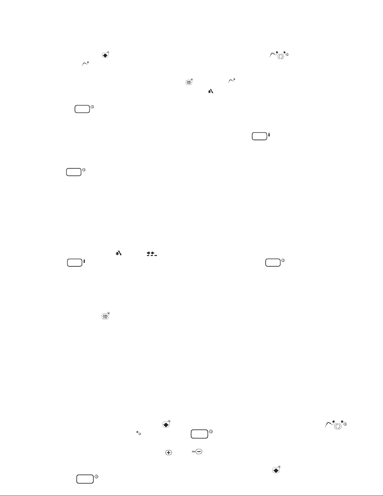
5.2 SOFT BLAST CHILLING BY TEMPERATURE (pre-cooked, hot foods)
• To select this cycle, press push-button 2 (relative LED lights up), then press push-button 5
to select the temperature mode (LED 5A on)
• Insert the core probe into the core of the product to be chilled.
• Start up the cycle by pressing push-button 6 . LED 5A and those related to the push-buttons
pressed illuminate throughout the cycle, while LEDs 12 ash.
• Display 15 indicates the maximum blast chilling time (starting temperature to end of the
blast chilling temperature (factory setting 90 minutes).
• The temperature measured by the core probe is shown by display 16 .
• The instrument timer starts the countdown of the maximum blast chilling time as soon as the temperature
measured by the core probe falls below the temperature of +149°F / +65°C (the dot at
the bottom right of display 15 ashes).
• During the blast chilling cycle, the air temperature is around +32°F / 0°C and may get as low as 23˚F/-5˚C.
This function is designed to guarantee uniform cooling of the product, preventing frost formation
on the surfaces. During the blast chilling cycle, the compressor may therefore stop and restart,
depending on the reading of the compartment temperature probe.
• The blast chilling phase ends only when the core probe (inserted in the product core) indicates
that the set blast chilling temperature (+38°F / +3°C) has been reached as signalled by an intermittent
beep for a minute. During the beep, LEDs 13 and 14 ash.
Display 16 indicates the temperature inside the compartment, while display 15 shows blast
chilling time reset to zero.
• If at the end of the maximum blast chilling interval the core probe continues to display a temperature
higher than the value for the end of blast chilling, the displays will indicate an alarm for
excessively long chilling (ALL 14) alternating with the temperature and time; at the same time, the
alarm beep will be activated.
The blast chilling cycle continues until the end chilling temperature has been reached; display 15
counts back the minutes remaining until the end of the cycle.
Press push-button 8 to mute the alarm; press push-button again to clear the alarm display.
Page 12

• At the end of the chilling cycle, the appliance automatically switches to the set storage temperature
PUSH-BUTTONS
:
ON /OFF (STAND BY)
SOFT BLAST CHILLING CYCLE (+38°F / +3°C)
HARD BLAST CHILLING CYCLE (+38°F / +3°C)
BLAST FREEZING CYCLE (0°F / -18°C)
END CYCLE BY TIME / PROBE (TEMPERATURE)
PROBE CHILLING INDICATOR LED
TIMED CHILLING INDICATOR LED
CYCLE START / STOP
INCREASE VALUE
DECREASE VALUE
RECIPE PROGRAMS (CHILLING CYCLES)
HACCP AND PRINTER (OPTIONAL)
DEFROSTING / FORCED VENTILATION
CHILLING / FREEZING CYCLE INDICATOR LED
HACCP
PROGRAM
0o
+38o
HARD
+38o
PUSH-BUTTONS
:
ON /OFF (STAND BY)
SOFT BLAST CHILLING CYCLE (+38°F / +3°C)
HARD BLAST CHILLING CYCLE (+38°F / +3°C)
BLAST FREEZING CYCLE (0°F / -18°C)
END CYCLE BY TIME / PROBE (TEMPERATURE)
PROBE CHILLING INDICATOR LED
TIMED CHILLING INDICATOR LED
CYCLE START / STOP
INCREASE VALUE
DECREASE VALUE
RECIPE PROGRAMS (CHILLING CYCLES)
HACCP AND PRINTER (OPTIONAL)
DEFROSTING / FORCED VENTILATION
CHILLING / FREEZING CYCLE INDICATOR LED
STORAGE INDICATOR LED
TIME DISPLAY
TEMPERATURE DISPLAY
oC
HACCP
PROGRAM
0o
+38o
HARD
+38o
PUSH-BUTTONS
:
ON /OFF (STAND BY)
SOFT BLAST CHILLING CYCLE (+38°F / +3°C)
HARD BLAST CHILLING CYCLE (+38°F / +3°C)
BLAST FREEZING CYCLE (0°F / -18°C)
END CYCLE BY TIME / PROBE (TEMPERATURE)
PROBE CHILLING INDICATOR LED
TIMED CHILLING INDICATOR LED
CYCLE START / STOP
0o
+38o
HARD
+38o
PUSH-BUTTONS
:
ON /OFF (STAND BY)
SOFT BLAST CHILLING CYCLE (+38°F / +3°C)
+38o
PUSH-BUTTONS
:
ON /OFF (STAND BY)
SOFT BLAST CHILLING CYCLE (+38°F / +3°C)
HARD BLAST CHILLING CYCLE (+38°F / +3°C)
BLAST FREEZING CYCLE (0°F / -18°C)
END CYCLE BY TIME / PROBE (TEMPERATURE)
0o
+38o
HARD
+38o
PUSH-BUTTONS
:
ON /OFF (STAND BY)
SOFT BLAST CHILLING CYCLE (+38°F / +3°C)
HARD BLAST CHILLING CYCLE (+38°F / +3°C)
BLAST FREEZING CYCLE (0°F / -18°C)
END CYCLE BY TIME / PROBE (TEMPERATURE)
PROBE CHILLING INDICATOR LED
TIMED CHILLING INDICATOR LED
0o
+38o
HARD
+38o
PUSH-BUTTONS
:
ON /OFF (STAND BY)
SOFT BLAST CHILLING CYCLE (+38°F / +3°C)
HARD BLAST CHILLING CYCLE (+38°F / +3°C)
BLAST FREEZING CYCLE (0°F / -18°C)
END CYCLE BY TIME / PROBE (TEMPERATURE)
PROBE CHILLING INDICATOR LED
TIMED CHILLING INDICATOR LED
CYCLE START / STOP
INCREASE VALUE
DECREASE VALUE
RECIPE PROGRAMS (CHILLING CYCLES)
HACCP AND PRINTER (OPTIONAL)
DEFROSTING / FORCED VENTILATION
CHILLING / FREEZING CYCLE INDICATOR LED
STORAGE INDICATOR LED
TIME DISPLAY
HACCP
PROGRAM
0o
+38o
HARD
+38o
PUSH-BUTTONS
:
ON /OFF (STAND BY)
SOFT BLAST CHILLING CYCLE (+38°F / +3°C)
HARD BLAST CHILLING CYCLE (+38°F / +3°C)
BLAST FREEZING CYCLE (0°F / -18°C)
END CYCLE BY TIME / PROBE (TEMPERATURE)
PROBE CHILLING INDICATOR LED
TIMED CHILLING INDICATOR LED
CYCLE START / STOP
INCREASE VALUE
DECREASE VALUE
0o
+38o
HARD
+38o
PUSH-BUTTONS
:
ON /OFF (STAND BY)
PUSH-BUTTONS
:
ON /OFF (STAND BY)
SOFT BLAST CHILLING CYCLE (+38°F / +3°C)
HARD BLAST CHILLING CYCLE (+38°F / +3°C)
BLAST FREEZING CYCLE (0°F / -18°C)
END CYCLE BY TIME / PROBE (TEMPERATURE)
PROBE CHILLING INDICATOR LED
TIMED CHILLING INDICATOR LED
0o
+38o
HARD
+38o
:
ON /OFF (STAND BY)
SOFT BLAST CHILLING CYCLE (+38°F / +3°C)
HARD BLAST CHILLING CYCLE (+38°F / +3°C)
BLAST FREEZING CYCLE (0°F / -18°C)
END CYCLE BY TIME / PROBE (TEMPERATURE)
PROBE CHILLING INDICATOR LED
TIMED CHILLING INDICATOR LED
CYCLE START / STOP
INCREASE VALUE
DECREASE VALUE
RECIPE PROGRAMS (CHILLING CYCLES)
HACCP AND PRINTER (OPTIONAL)
DEFROSTING / FORCED VENTILATION
CHILLING / FREEZING CYCLE INDICATOR LED
HACCP
PROGRAM
0o
+38o
HARD
+38o
PUSH-BUTTONS
:
ON /OFF (STAND BY)
SOFT BLAST CHILLING CYCLE (+38°F / +3°C)
HARD BLAST CHILLING CYCLE (+38°F / +3°C)
BLAST FREEZING CYCLE (0°F / -18°C)
END CYCLE BY TIME / PROBE (TEMPERATURE)
PROBE CHILLING INDICATOR LED
TIMED CHILLING INDICATOR LED
CYCLE START / STOP
INCREASE VALUE
DECREASE VALUE
RECIPE PROGRAMS (CHILLING CYCLES)
HACCP AND PRINTER (OPTIONAL)
DEFROSTING / FORCED VENTILATION
CHILLING / FREEZING CYCLE INDICATOR LED
STORAGE INDICATOR LED
TIME DISPLAY
TEMPERATURE DISPLAY
oC
HACCP
PROGRAM
0o
+38o
HARD
+38o
PUSH-BUTTONS
:
ON /OFF (STAND BY)
for an indenite interval (like a standard storage appliance).
LEDs 13 switch o while LEDs 14 light up.
• The compartment temperature is constantly shown on display 16; during this cycle, defrost
cycles are performed at regular intervals with duration set as required (parameter programming reserved for
installation technician). The factory setting for positive storage temperature is +36°F / +2°C.
• Press push-button 6 to set the appliance to STOP status (relative LED switches o), ready for a new
cycle.
To modify the nal blast chilling temperature, consult the user programming instructions.
IMPORTANT: During chilling or shock freezing by core sensor it’s possible to read:
- The room temperature by pressing push button
- The evaporator temperature by pressing push button
5.3 SOFT TIMED BLAST CHILLING
• Press push-button 2 (relative LED lights up), then press push-button 5 to select the timer mode
(LED 5B on). Display 15 shows the maximum chilling time (set by default to 90 minutes).
To modify this time, press push-buttons 7 and 8 (time in minutes).
• Press push-button 6 to start the appliance. LED 5B and push-button LEDs remain on and LEDs 13
ash throughout the cycle.
Internal cell temperature is shown on display 16 .
• When the maximum chilling time has counted back to 0, the chilling cycle is completed and the appliance
automatically switches to the set positive storage temperature for an indenite interval.
• LEDs illuminate and the beep is activated when the cycle is nished (as in the chilling cycle by
temperature). The same applies for the positive storage function.
Press push-button 6 to set the appliance to STOP status (relative LED switches o), ready for a new cycle.
IMPORTANT: Use the storage function sparingly. After chilling, food products should be placed in
storage cabinets.
HARD BLAST CHILLING
When the HARD function is used, chilling takes place in two stages:
• an initial “Hard” stage when the air temperature is brought down to below 32°F / 0°C in order to accelerate
chilling;
• a second “Soft” stage, involving air temperatures around 32°F.
IMPORTANT: During chilling or shock freezing by time it’s possible to read the evaporator
temperature by pressing push button
Page 13
5.4 HARD BLAST CHILLING BY TEMPERATURE
PUSH-BUTTONS
:
ON /OFF (STAND BY)
SOFT BLAST CHILLING CYCLE (+38°F / +3°C)
HARD BLAST CHILLING CYCLE (+38°F / +3°C)
+38o
HARD
+38o
PUSH-BUTTONS
:
ON /OFF (STAND BY)
SOFT BLAST CHILLING CYCLE (+38°F / +3°C)
HARD BLAST CHILLING CYCLE (+38°F / +3°C)
BLAST FREEZING CYCLE (0°F / -18°C)
END CYCLE BY TIME / PROBE (TEMPERATURE)
0o
+38o
HARD
+38o
PUSH-BUTTONS
:
ON /OFF (STAND BY)
SOFT BLAST CHILLING CYCLE (+38°F / +3°C)
HARD BLAST CHILLING CYCLE (+38°F / +3°C)
BLAST FREEZING CYCLE (0°F / -18°C)
END CYCLE BY TIME / PROBE (TEMPERATURE)
PROBE CHILLING INDICATOR LED
0o
+38o
HARD
+38o
PUSH-BUTTONS
:
ON /OFF (STAND BY)
SOFT BLAST CHILLING CYCLE (+38°F / +3°C)
HARD BLAST CHILLING CYCLE (+38°F / +3°C)
BLAST FREEZING CYCLE (0°F / -18°C)
END CYCLE BY TIME / PROBE (TEMPERATURE)
PROBE CHILLING INDICATOR LED
TIMED CHILLING INDICATOR LED
CYCLE START / STOP
0o
+38o
HARD
+38o
PUSH-BUTTONS
:
ON /OFF (STAND BY)
SOFT BLAST CHILLING CYCLE (+38°F / +3°C)
HARD BLAST CHILLING CYCLE (+38°F / +3°C)
BLAST FREEZING CYCLE (0°F / -18°C)
END CYCLE BY TIME / PROBE (TEMPERATURE)
PROBE CHILLING INDICATOR LED
0o
+38o
HARD
+38o
PUSH-BUTTONS
:
ON /OFF (STAND BY)
SOFT BLAST CHILLING CYCLE (+38°F / +3°C)
HARD BLAST CHILLING CYCLE (+38°F / +3°C)
BLAST FREEZING CYCLE (0°F / -18°C)
END CYCLE BY TIME / PROBE (TEMPERATURE)
PROBE CHILLING INDICATOR LED
TIMED CHILLING INDICATOR LED
CYCLE START / STOP
INCREASE VALUE
DECREASE VALUE
RECIPE PROGRAMS (CHILLING CYCLES)
HACCP AND PRINTER (OPTIONAL)
DEFROSTING / FORCED VENTILATION
CHILLING / FREEZING CYCLE INDICATOR LED
HACCP
PROGRAM
0o
+38o
HARD
+38o
PUSH-BUTTONS
:
ON /OFF (STAND BY)
SOFT BLAST CHILLING CYCLE (+38°F / +3°C)
HARD BLAST CHILLING CYCLE (+38°F / +3°C)
BLAST FREEZING CYCLE (0°F / -18°C)
END CYCLE BY TIME / PROBE (TEMPERATURE)
PROBE CHILLING INDICATOR LED
TIMED CHILLING INDICATOR LED
CYCLE START / STOP
INCREASE VALUE
DECREASE VALUE
RECIPE PROGRAMS (CHILLING CYCLES)
HACCP AND PRINTER (OPTIONAL)
DEFROSTING / FORCED VENTILATION
CHILLING / FREEZING CYCLE INDICATOR LED
STORAGE INDICATOR LED
TIME DISPLAY
TEMPERATURE DISPLAY
oC
HACCP
PROGRAM
0o
+38o
HARD
+38o
PUSH-BUTTONS
:
ON /OFF (STAND BY)
SOFT BLAST CHILLING CYCLE (+38°F / +3°C)
HARD BLAST CHILLING CYCLE (+38°F / +3°C)
BLAST FREEZING CYCLE (0°F / -18°C)
END CYCLE BY TIME / PROBE (TEMPERATURE)
PROBE CHILLING INDICATOR LED
TIMED CHILLING INDICATOR LED
CYCLE START / STOP
INCREASE VALUE
DECREASE VALUE
RECIPE PROGRAMS (CHILLING CYCLES)
HACCP AND PRINTER (OPTIONAL)
DEFROSTING / FORCED VENTILATION
CHILLING / FREEZING CYCLE INDICATOR LED
STORAGE INDICATOR LED
TIME DISPLAY
TEMPERATURE DISPLAY
oC
HACCP
PROGRAM
0o
+38o
HARD
+38o
PUSH-BUTTONS
:
ON /OFF (STAND BY)
SOFT BLAST CHILLING CYCLE (+38°F / +3°C)
HARD BLAST CHILLING CYCLE (+38°F / +3°C)
BLAST FREEZING CYCLE (0°F / -18°C)
END CYCLE BY TIME / PROBE (TEMPERATURE)
PROBE CHILLING INDICATOR LED
TIMED CHILLING INDICATOR LED
CYCLE START / STOP
INCREASE VALUE
DECREASE VALUE
RECIPE PROGRAMS (CHILLING CYCLES)
HACCP AND PRINTER (OPTIONAL)
DEFROSTING / FORCED VENTILATION
CHILLING / FREEZING CYCLE INDICATOR LED
STORAGE INDICATOR LED
HACCP
PROGRAM
0o
+38o
HARD
+38o
PUSH-BUTTONS
:
ON /OFF (STAND BY)
SOFT BLAST CHILLING CYCLE (+38°F / +3°C)
HARD BLAST CHILLING CYCLE (+38°F / +3°C)
BLAST FREEZING CYCLE (0°F / -18°C)
END CYCLE BY TIME / PROBE (TEMPERATURE)
PROBE CHILLING INDICATOR LED
TIMED CHILLING INDICATOR LED
CYCLE START / STOP
0o
+38o
HARD
+38o
PUSH-BUTTONS
:
ON /OFF (STAND BY)
SOFT BLAST CHILLING CYCLE (+38°F / +3°C)
HARD BLAST CHILLING CYCLE (+38°F / +3°C)
+38o
HARD
+38o
PUSH-BUTTONS
:
ON /OFF (STAND BY)
SOFT BLAST CHILLING CYCLE (+38°F / +3°C)
HARD BLAST CHILLING CYCLE (+38°F / +3°C)
BLAST FREEZING CYCLE (0°F / -18°C)
END CYCLE BY TIME / PROBE (TEMPERATURE)
0o
+38o
HARD
+38o
PUSH-BUTTONS
:
ON /OFF (STAND BY)
SOFT BLAST CHILLING CYCLE (+38°F / +3°C)
HARD BLAST CHILLING CYCLE (+38°F / +3°C)
BLAST FREEZING CYCLE (0°F / -18°C)
END CYCLE BY TIME / PROBE (TEMPERATURE)
PROBE CHILLING INDICATOR LED
TIMED CHILLING INDICATOR LED
0o
+38o
HARD
+38o
PUSH-BUTTONS
:
ON /OFF (STAND BY)
SOFT BLAST CHILLING CYCLE (+38°F / +3°C)
HARD BLAST CHILLING CYCLE (+38°F / +3°C)
BLAST FREEZING CYCLE (0°F / -18°C)
END CYCLE BY TIME / PROBE (TEMPERATURE)
PROBE CHILLING INDICATOR LED
TIMED CHILLING INDICATOR LED
CYCLE START / STOP
INCREASE VALUE
DECREASE VALUE
RECIPE PROGRAMS (CHILLING CYCLES)
HACCP AND PRINTER (OPTIONAL)
DEFROSTING / FORCED VENTILATION
CHILLING / FREEZING CYCLE INDICATOR LED
STORAGE INDICATOR LED
TIME DISPLAY
HACCP
PROGRAM
0o
+38o
HARD
+38o
PUSH-BUTTONS
:
ON /OFF (STAND BY)
SOFT BLAST CHILLING CYCLE (+38°F / +3°C)
HARD BLAST CHILLING CYCLE (+38°F / +3°C)
BLAST FREEZING CYCLE (0°F / -18°C)
END CYCLE BY TIME / PROBE (TEMPERATURE)
PROBE CHILLING INDICATOR LED
TIMED CHILLING INDICATOR LED
CYCLE START / STOP
INCREASE VALUE
DECREASE VALUE
0o
+38o
HARD
+38o
PUSH-BUTTONS
:
ON /OFF (STAND BY)
SOFT BLAST CHILLING CYCLE (+38°F / +3°C)
HARD BLAST CHILLING CYCLE (+38°F / +3°C)
+38o
HARD
+38o
PUSH-BUTTONS
:
ON /OFF (STAND BY)
SOFT BLAST CHILLING CYCLE (+38°F / +3°C)
HARD BLAST CHILLING CYCLE (+38°F / +3°C)
BLAST FREEZING CYCLE (0°F / -18°C)
END CYCLE BY TIME / PROBE (TEMPERATURE)
PROBE CHILLING INDICATOR LED
TIMED CHILLING INDICATOR LED
CYCLE START / STOP
INCREASE VALUE
DECREASE VALUE
RECIPE PROGRAMS (CHILLING CYCLES)
HACCP AND PRINTER (OPTIONAL)
DEFROSTING / FORCED VENTILATION
CHILLING / FREEZING CYCLE INDICATOR LED
STORAGE INDICATOR LED
TIME DISPLAY
HACCP
PROGRAM
0o
+38o
HARD
+38o
• Press push-button 3 (relative LED lights up), then press push-button 5 to select the temperature
mode (LED 5A on). Insert the core probe into the core of the product to be chilled.
• Start up the cycle by pressing push-button 6 . LED 5A and those relative to the push-buttons
pressed illuminate throughout the cycle, while LEDs 13 ash.
• Display 15 indicates the maximum blast chilling time (starting temperature to end of the blast
chilling temperature - factory setting - 90 minutes).
• The temperature measured by the core probe is shown by display 16 .
• The instrument timer starts the countdown of the maximum blast chilling time as soon as the temperature
measured by the core probe falls below the temperature of +149°F / +65°C (the dot at the bottom right of
display 15 ashes).
• Once the cycle has been started, the appliance operates initially with an air temperature below +32°F / 0°C
(LED on push-button 3 ashes), then with temperatures around +32°F / 0°C (LED on push-button 3 on).
The rst stage of the cycle is completed when the core probe detects a temperature of +68°F / +20°C in the
product core.
• The blast chilling phase ends only when the core probe (inserted in the product core) indicates that the set
blast chilling temperature (+38°F / +3°C) has been reached as signalled by an intermittent beep for a minute.
During the beep, LEDs 13 and 14 ash.
Display 16 indicates the temperature inside the cell, while display 15 shows blast chilling time
reset to zero.
• The alarm (ALL 14) and conservation functions cut in with relative indicators in the same way as for timed
Soft blast chilling.
• Press push-button 6 to set the appliance to STOP status (relative LED switches o), ready for a new cycle.
IMPORTANT
HARD blast chilling aords a considerable reduction in working time, and is particularly suited to foods with
a high fat content, for large pieces or for packaged products.
SOFT chilling is recommended for delicate and nely chopped products, such as vegetables, mousses, etc..
IMPORTANT: During chilling or shock freezing by core sensor it’s possible to read:
- The evaporator temperature by pressing push button
5.5 HARD TIMED BLAST CHILLING
• To select this cycle, press push-button 3 (relative LED lights up), then press push-button 5 to
select the “timed” mode (LED 5B on). Display 15 shows the maximum chilling time (set by default
to 90 minutes).
To modify this time, press push-buttons 7 and 8 (time in minutes).
• To set the time of the rst negative temperature stage, press push-button 3 for ve seconds, then wait
for display 15 to show the ashing value.
Page 14

The time setting (in minutes) can be modied by means of push-buttons 7
PUSH-BUTTONS
:
ON /OFF (STAND BY)
SOFT BLAST CHILLING CYCLE (+38°F / +3°C)
HARD BLAST CHILLING CYCLE (+38°F / +3°C)
BLAST FREEZING CYCLE (0°F / -18°C)
END CYCLE BY TIME / PROBE (TEMPERATURE)
PROBE CHILLING INDICATOR LED
TIMED CHILLING INDICATOR LED
CYCLE START / STOP
INCREASE VALUE
0o
+38o
HARD
+38o
PUSH-BUTTONS
:
ON /OFF (STAND BY)
SOFT BLAST CHILLING CYCLE (+38°F / +3°C)
HARD BLAST CHILLING CYCLE (+38°F / +3°C)
BLAST FREEZING CYCLE (0°F / -18°C)
END CYCLE BY TIME / PROBE (TEMPERATURE)
PROBE CHILLING INDICATOR LED
TIMED CHILLING INDICATOR LED
CYCLE START / STOP
INCREASE VALUE
DECREASE VALUE
0o
+38o
HARD
+38o
PUSH-BUTTONS
:
ON /OFF (STAND BY)
SOFT BLAST CHILLING CYCLE (+38°F / +3°C)
HARD BLAST CHILLING CYCLE (+38°F / +3°C)
+38o
HARD
+38o
PUSH-BUTTONS
:
ON /OFF (STAND BY)
SOFT BLAST CHILLING CYCLE (+38°F / +3°C)
HARD BLAST CHILLING CYCLE (+38°F / +3°C)
BLAST FREEZING CYCLE (0°F / -18°C)
END CYCLE BY TIME / PROBE (TEMPERATURE)
PROBE CHILLING INDICATOR LED
TIMED CHILLING INDICATOR LED
CYCLE START / STOP
0o
+38o
HARD
+38o
PUSH-BUTTONS
:
ON /OFF (STAND BY)
SOFT BLAST CHILLING CYCLE (+38°F / +3°C)
HARD BLAST CHILLING CYCLE (+38°F / +3°C)
BLAST FREEZING CYCLE (0°F / -18°C)
END CYCLE BY TIME / PROBE (TEMPERATURE)
PROBE CHILLING INDICATOR LED
TIMED CHILLING INDICATOR LED
0o
+38o
HARD
+38o
PUSH-BUTTONS
:
ON /OFF (STAND BY)
SOFT BLAST CHILLING CYCLE (+38°F / +3°C)
HARD BLAST CHILLING CYCLE (+38°F / +3°C)
BLAST FREEZING CYCLE (0°F / -18°C)
END CYCLE BY TIME / PROBE (TEMPERATURE)
PROBE CHILLING INDICATOR LED
TIMED CHILLING INDICATOR LED
CYCLE START / STOP
INCREASE VALUE
DECREASE VALUE
RECIPE PROGRAMS (CHILLING CYCLES)
HACCP AND PRINTER (OPTIONAL)
DEFROSTING / FORCED VENTILATION
CHILLING / FREEZING CYCLE INDICATOR LED
HACCP
PROGRAM
0o
+38o
HARD
+38o
PUSH-BUTTONS
:
ON /OFF (STAND BY)
SOFT BLAST CHILLING CYCLE (+38°F / +3°C)
HARD BLAST CHILLING CYCLE (+38°F / +3°C)
BLAST FREEZING CYCLE (0°F / -18°C)
END CYCLE BY TIME / PROBE (TEMPERATURE)
PROBE CHILLING INDICATOR LED
TIMED CHILLING INDICATOR LED
CYCLE START / STOP
INCREASE VALUE
DECREASE VALUE
RECIPE PROGRAMS (CHILLING CYCLES)
HACCP AND PRINTER (OPTIONAL)
DEFROSTING / FORCED VENTILATION
CHILLING / FREEZING CYCLE INDICATOR LED
STORAGE INDICATOR LED
TIME DISPLAY
TEMPERATURE DISPLAY
oC
HACCP
PROGRAM
0o
+38o
HARD
+38o
PUSH-BUTTONS
:
ON /OFF (STAND BY)
SOFT BLAST CHILLING CYCLE (+38°F / +3°C)
HARD BLAST CHILLING CYCLE (+38°F / +3°C)
+38o
HARD
+38o
PUSH-BUTTONS
:
ON /OFF (STAND BY)
SOFT BLAST CHILLING CYCLE (+38°F / +3°C)
HARD BLAST CHILLING CYCLE (+38°F / +3°C)
+38o
HARD
+38o
PUSH-BUTTONS
:
ON /OFF (STAND BY)
SOFT BLAST CHILLING CYCLE (+38°F / +3°C)
HARD BLAST CHILLING CYCLE (+38°F / +3°C)
BLAST FREEZING CYCLE (0°F / -18°C)
END CYCLE BY TIME / PROBE (TEMPERATURE)
PROBE CHILLING INDICATOR LED
TIMED CHILLING INDICATOR LED
CYCLE START / STOP
0o
+38o
HARD
+38o
PUSH-BUTTONS
:
ON /OFF (STAND BY)
SOFT BLAST CHILLING CYCLE (+38°F / +3°C)
HARD BLAST CHILLING CYCLE (+38°F / +3°C)
BLAST FREEZING CYCLE (0°F / -18°C)
0o
+38o
HARD
+38o
PUSH-BUTTONS
:
ON /OFF (STAND BY)
SOFT BLAST CHILLING CYCLE (+38°F / +3°C)
HARD BLAST CHILLING CYCLE (+38°F / +3°C)
BLAST FREEZING CYCLE (0°F / -18°C)
END CYCLE BY TIME / PROBE (TEMPERATURE)
0o
+38o
HARD
+38o
PUSH-BUTTONS
:
ON /OFF (STAND BY)
SOFT BLAST CHILLING CYCLE (+38°F / +3°C)
HARD BLAST CHILLING CYCLE (+38°F / +3°C)
BLAST FREEZING CYCLE (0°F / -18°C)
END CYCLE BY TIME / PROBE (TEMPERATURE)
PROBE CHILLING INDICATOR LED
0o
+38o
HARD
+38o
PUSH-BUTTONS
:
ON /OFF (STAND BY)
SOFT BLAST CHILLING CYCLE (+38°F / +3°C)
HARD BLAST CHILLING CYCLE (+38°F / +3°C)
BLAST FREEZING CYCLE (0°F / -18°C)
END CYCLE BY TIME / PROBE (TEMPERATURE)
PROBE CHILLING INDICATOR LED
TIMED CHILLING INDICATOR LED
CYCLE START / STOP
0o
+38o
HARD
+38o
PUSH-BUTTONS
:
ON /OFF (STAND BY)
SOFT BLAST CHILLING CYCLE (+38°F / +3°C)
HARD BLAST CHILLING CYCLE (+38°F / +3°C)
BLAST FREEZING CYCLE (0°F / -18°C)
END CYCLE BY TIME / PROBE (TEMPERATURE)
PROBE CHILLING INDICATOR LED
0o
+38o
HARD
+38o
PUSH-BUTTONS
:
ON /OFF (STAND BY)
SOFT BLAST CHILLING CYCLE (+38°F / +3°C)
HARD BLAST CHILLING CYCLE (+38°F / +3°C)
BLAST FREEZING CYCLE (0°F / -18°C)
END CYCLE BY TIME / PROBE (TEMPERATURE)
PROBE CHILLING INDICATOR LED
TIMED CHILLING INDICATOR LED
CYCLE START / STOP
INCREASE VALUE
DECREASE VALUE
RECIPE PROGRAMS (CHILLING CYCLES)
HACCP AND PRINTER (OPTIONAL)
DEFROSTING / FORCED VENTILATION
CHILLING / FREEZING CYCLE INDICATOR LED
HACCP
PROGRAM
0o
+38o
HARD
+38o
PUSH-BUTTONS
:
ON /OFF (STAND BY)
SOFT BLAST CHILLING CYCLE (+38°F / +3°C)
HARD BLAST CHILLING CYCLE (+38°F / +3°C)
BLAST FREEZING CYCLE (0°F / -18°C)
END CYCLE BY TIME / PROBE (TEMPERATURE)
PROBE CHILLING INDICATOR LED
TIMED CHILLING INDICATOR LED
CYCLE START / STOP
0o
+38o
HARD
+38o
PUSH-BUTTONS
:
ON /OFF (STAND BY)
SOFT BLAST CHILLING CYCLE (+38°F / +3°C)
HARD BLAST CHILLING CYCLE (+38°F / +3°C)
BLAST FREEZING CYCLE (0°F / -18°C)
END CYCLE BY TIME / PROBE (TEMPERATURE)
PROBE CHILLING INDICATOR LED
TIMED CHILLING INDICATOR LED
CYCLE START / STOP
INCREASE VALUE
DECREASE VALUE
RECIPE PROGRAMS (CHILLING CYCLES)
HACCP AND PRINTER (OPTIONAL)
HACCP
PROGRAM
0o
+38o
HARD
+38o
Press push-button 3
again to return to standard display.
and 8
.
• Start up the cycle by pressing push-button 6
LEDs 13
ash throughout the cycle.
• Internal cell temperature is shown on display 16
. LED 5B
and push-button LEDs remain on and
.
• Once the cycle has been started, the appliance operates initially with an air temperature below +32°F /
0°C (LED on push-button 3
3
on). For example: HARD timed chilling cycle 90 minutes. First stage of 40 minutes with negative air
ashes), then with temperatures around +32°F / 0°C (LED on push-button
temperature. Second cycle stage of 50 minutes with air temperature around +32°F / 0°C.
• When the maximum chilling time has counted back to 0, the chilling cycle is completed and the appliance
automatically switches to the set positive storage temperature for an indenite interval.
• LEDs illuminate and the beep is activated when the cycle is nished (as in the temperature chilling cycle).
The same applies for the storage function.
• Press push-button 6 to set the appliance to STOP status (relative LED switches o), ready for a new
cycle.
IMPORTANT: During chilling or shock freezing by time it’s possible to read the evaporator temperature by
pressing push button
5.6 BLAST FREEZING BY TEMPERATURE
• To select this cycle, press push-button 4 (relative LED lights up), then press push-button 5 to
select the temperature mode (LED 5A on). Insert the core probe into the core of the product to be chilled.
• Start up the cycle by pressing push-button 6 . LED 5A and those relative to the pushbuttons pressed
illuminate throughout the cycle, while LEDs 13 ash.
• The appliance proceeds to operate in the same way as that described for the positive chilling cycle.
During this cycle the compressor operates in continuous mode to enable the appliance to reach the cycle
end temperature in the shortest time possible (default temperature at product core is set at 0°F / -18°C).
Maximum freezing time is 240 minutes.
• The alarm (ALL 14) for excessively-long freezing and conservation functions cut in with relative indicators in
the same way as for timed Soft blast chilling. The factory setting for negative storage temperature is -13°F /
-25°C.
• LEDs illuminate and the beep is activated when the cycle is nished (as in the soft chilling cycle by
temperature). The same applies for the storage function.
Press push-button 6 to set the appliance to STOP status (relative LED switches o), ready for a new cycle.
IMPORTANT: During chilling or shock freezing by core sensor it’s possible to read:
- The evaporator temperature by pressing push button
Page 15

5.7 TIMED BLAST FREEZING
PUSH-BUTTONS
:
ON /OFF (STAND BY)
SOFT BLAST CHILLING CYCLE (+38°F / +3°C)
HARD BLAST CHILLING CYCLE (+38°F / +3°C)
BLAST FREEZING CYCLE (0°F / -18°C)
0o
+38o
HARD
+38o
PUSH-BUTTONS
:
ON /OFF (STAND BY)
SOFT BLAST CHILLING CYCLE (+38°F / +3°C)
HARD BLAST CHILLING CYCLE (+38°F / +3°C)
BLAST FREEZING CYCLE (0°F / -18°C)
END CYCLE BY TIME / PROBE (TEMPERATURE)
0o
+38o
HARD
+38o
PUSH-BUTTONS
:
ON /OFF (STAND BY)
SOFT BLAST CHILLING CYCLE (+38°F / +3°C)
HARD BLAST CHILLING CYCLE (+38°F / +3°C)
BLAST FREEZING CYCLE (0°F / -18°C)
END CYCLE BY TIME / PROBE (TEMPERATURE)
PROBE CHILLING INDICATOR LED
TIMED CHILLING INDICATOR LED
0o
+38o
HARD
+38o
PUSH-BUTTONS
:
ON /OFF (STAND BY)
SOFT BLAST CHILLING CYCLE (+38°F / +3°C)
HARD BLAST CHILLING CYCLE (+38°F / +3°C)
BLAST FREEZING CYCLE (0°F / -18°C)
END CYCLE BY TIME / PROBE (TEMPERATURE)
PROBE CHILLING INDICATOR LED
TIMED CHILLING INDICATOR LED
CYCLE START / STOP
INCREASE VALUE
DECREASE VALUE
RECIPE PROGRAMS (CHILLING CYCLES)
HACCP AND PRINTER (OPTIONAL)
DEFROSTING / FORCED VENTILATION
CHILLING / FREEZING CYCLE INDICATOR LED
STORAGE INDICATOR LED
TIME DISPLAY
HACCP
PROGRAM
0o
+38o
HARD
+38o
PUSH-BUTTONS
:
ON /OFF (STAND BY)
SOFT BLAST CHILLING CYCLE (+38°F / +3°C)
HARD BLAST CHILLING CYCLE (+38°F / +3°C)
BLAST FREEZING CYCLE (0°F / -18°C)
END CYCLE BY TIME / PROBE (TEMPERATURE)
PROBE CHILLING INDICATOR LED
TIMED CHILLING INDICATOR LED
CYCLE START / STOP
INCREASE VALUE
DECREASE VALUE
0o
+38o
HARD
+38o
PUSH-BUTTONS
:
ON /OFF (STAND BY)
SOFT BLAST CHILLING CYCLE (+38°F / +3°C)
HARD BLAST CHILLING CYCLE (+38°F / +3°C)
BLAST FREEZING CYCLE (0°F / -18°C)
END CYCLE BY TIME / PROBE (TEMPERATURE)
PROBE CHILLING INDICATOR LED
TIMED CHILLING INDICATOR LED
CYCLE START / STOP
0o
+38o
HARD
+38o
PUSH-BUTTONS
:
ON /OFF (STAND BY)
SOFT BLAST CHILLING CYCLE (+38°F / +3°C)
HARD BLAST CHILLING CYCLE (+38°F / +3°C)
BLAST FREEZING CYCLE (0°F / -18°C)
END CYCLE BY TIME / PROBE (TEMPERATURE)
PROBE CHILLING INDICATOR LED
TIMED CHILLING INDICATOR LED
0o
+38o
HARD
+38o
PUSH-BUTTONS
:
ON /OFF (STAND BY)
SOFT BLAST CHILLING CYCLE (+38°F / +3°C)
HARD BLAST CHILLING CYCLE (+38°F / +3°C)
BLAST FREEZING CYCLE (0°F / -18°C)
END CYCLE BY TIME / PROBE (TEMPERATURE)
PROBE CHILLING INDICATOR LED
TIMED CHILLING INDICATOR LED
CYCLE START / STOP
INCREASE VALUE
DECREASE VALUE
RECIPE PROGRAMS (CHILLING CYCLES)
HACCP AND PRINTER (OPTIONAL)
DEFROSTING / FORCED VENTILATION
CHILLING / FREEZING CYCLE INDICATOR LED
HACCP
PROGRAM
0o
+38o
HARD
+38o
PUSH-BUTTONS
:
ON /OFF (STAND BY)
SOFT BLAST CHILLING CYCLE (+38°F / +3°C)
HARD BLAST CHILLING CYCLE (+38°F / +3°C)
BLAST FREEZING CYCLE (0°F / -18°C)
END CYCLE BY TIME / PROBE (TEMPERATURE)
PROBE CHILLING INDICATOR LED
TIMED CHILLING INDICATOR LED
CYCLE START / STOP
INCREASE VALUE
DECREASE VALUE
RECIPE PROGRAMS (CHILLING CYCLES)
HACCP AND PRINTER (OPTIONAL)
DEFROSTING / FORCED VENTILATION
CHILLING / FREEZING CYCLE INDICATOR LED
STORAGE INDICATOR LED
TIME DISPLAY
TEMPERATURE DISPLAY
oC
HACCP
PROGRAM
0o
+38o
HARD
+38o
PUSH-BUTTONS
:
ON /OFF (STAND BY)
SOFT BLAST CHILLING CYCLE (+38°F / +3°C)
HARD BLAST CHILLING CYCLE (+38°F / +3°C)
BLAST FREEZING CYCLE (0°F / -18°C)
END CYCLE BY TIME / PROBE (TEMPERATURE)
PROBE CHILLING INDICATOR LED
TIMED CHILLING INDICATOR LED
CYCLE START / STOP
0o
+38o
HARD
+38o
PUSH-BUTTONS
:
ON /OFF (STAND BY)
SOFT BLAST CHILLING CYCLE (+38°F / +3°C)
HARD BLAST CHILLING CYCLE (+38°F / +3°C)
BLAST FREEZING CYCLE (0°F / -18°C)
END CYCLE BY TIME / PROBE (TEMPERATURE)
PROBE CHILLING INDICATOR LED
TIMED CHILLING INDICATOR LED
CYCLE START / STOP
INCREASE VALUE
DECREASE VALUE
RECIPE PROGRAMS (CHILLING CYCLES)
HACCP AND PRINTER (OPTIONAL)
HACCP
PROGRAM
0o
+38o
HARD
+38o
• Press push-button 4
(LED 5B
on). Display 15
To modify this time, press push-buttons 7
• Start up the cycle by pressing push-button 6
LEDs 13
ash throughout the cycle.
Internal cell temperature is shown on display 16
(relative LED lights up), then press push-button 5
shows the maximum chilling time (set by default to 240 minutes).
and 8
(time in minutes).
. LED 5B
and push-button LEDs remain on and
.
to select the timer mode
• When the maximum chilling time has counted back to 0, the cycle is completed and the appliance
automatically switches to the set negative storage temperature for an indenite interval.
LEDs illuminate and the beep is activated when the cycle is nished (as in the freezing cycle by temperature).
The same applies for the storage function. The factory setting for negative storage temperature is -13°F /
-25°C.
• Press push-button 6
to set the appliance to STOP status (relative LED switches o), ready for a new
cycle.
IMPORTANT: During chilling or shock freezing by time it’s possible to read the evaporator temperature by
pressing push button
Page 16

PUSH-BUTTONS
:
ON /OFF (STAND BY)
PUSH-BUTTONS
:
ON /OFF (STAND BY)
SOFT BLAST CHILLING CYCLE (+38°F / +3°C)
HARD BLAST CHILLING CYCLE (+38°F / +3°C)
BLAST FREEZING CYCLE (0°F / -18°C)
END CYCLE BY TIME / PROBE (TEMPERATURE)
0o
+38o
HARD
+38o
PUSH-BUTTONS
:
ON /OFF (STAND BY)
SOFT BLAST CHILLING CYCLE (+38°F / +3°C)
HARD BLAST CHILLING CYCLE (+38°F / +3°C)
BLAST FREEZING CYCLE (0°F / -18°C)
END CYCLE BY TIME / PROBE (TEMPERATURE)
PROBE CHILLING INDICATOR LED
TIMED CHILLING INDICATOR LED
CYCLE START / STOP
INCREASE VALUE
DECREASE VALUE
RECIPE PROGRAMS (CHILLING CYCLES)
HACCP AND PRINTER (OPTIONAL)
DEFROSTING / FORCED VENTILATION
CHILLING / FREEZING CYCLE INDICATOR LED
STORAGE INDICATOR LED
TIME DISPLAY
TEMPERATURE DISPLAY
oC
HACCP
PROGRAM
0o
+38o
HARD
+38o
PUSH-BUTTONS
:
ON /OFF (STAND BY)
SOFT BLAST CHILLING CYCLE (+38°F / +3°C)
HARD BLAST CHILLING CYCLE (+38°F / +3°C)
BLAST FREEZING CYCLE (0°F / -18°C)
END CYCLE BY TIME / PROBE (TEMPERATURE)
PROBE CHILLING INDICATOR LED
TIMED CHILLING INDICATOR LED
CYCLE START / STOP
INCREASE VALUE
DECREASE VALUE
RECIPE PROGRAMS (CHILLING CYCLES)
HACCP AND PRINTER (OPTIONAL)
DEFROSTING / FORCED VENTILATION
CHILLING / FREEZING CYCLE INDICATOR LED
STORAGE INDICATOR LED
TIME DISPLAY
HACCP
PROGRAM
0o
+38o
HARD
+38o
PUSH-BUTTONS
:
ON /OFF (STAND BY)
SOFT BLAST CHILLING CYCLE (+38°F / +3°C)
HARD BLAST CHILLING CYCLE (+38°F / +3°C)
BLAST FREEZING CYCLE (0°F / -18°C)
END CYCLE BY TIME / PROBE (TEMPERATURE)
0o
+38o
HARD
+38o
PUSH-BUTTONS
:
ON /OFF (STAND BY)
SOFT BLAST CHILLING CYCLE (+38°F / +3°C)
HARD BLAST CHILLING CYCLE (+38°F / +3°C)
BLAST FREEZING CYCLE (0°F / -18°C)
END CYCLE BY TIME / PROBE (TEMPERATURE)
PROBE CHILLING INDICATOR LED
TIMED CHILLING INDICATOR LED
CYCLE START / STOP
INCREASE VALUE
DECREASE VALUE
0o
+38o
HARD
+38o
PUSH-BUTTONS
:
ON /OFF (STAND BY)
PUSH-BUTTONS
:
ON /OFF (STAND BY)
SOFT BLAST CHILLING CYCLE (+38°F / +3°C)
HARD BLAST CHILLING CYCLE (+38°F / +3°C)
BLAST FREEZING CYCLE (0°F / -18°C)
END CYCLE BY TIME / PROBE (TEMPERATURE)
PROBE CHILLING INDICATOR LED
TIMED CHILLING INDICATOR LED
CYCLE START / STOP
0o
+38o
HARD
+38o
PUSH-BUTTONS
:
ON /OFF (STAND BY)
SOFT BLAST CHILLING CYCLE (+38°F / +3°C)
HARD BLAST CHILLING CYCLE (+38°F / +3°C)
BLAST FREEZING CYCLE (0°F / -18°C)
END CYCLE BY TIME / PROBE (TEMPERATURE)
PROBE CHILLING INDICATOR LED
TIMED CHILLING INDICATOR LED
CYCLE START / STOP
INCREASE VALUE
DECREASE VALUE
RECIPE PROGRAMS (CHILLING CYCLES)
HACCP AND PRINTER (OPTIONAL)
DEFROSTING / FORCED VENTILATION
CHILLING / FREEZING CYCLE INDICATOR LED
STORAGE INDICATOR LED
TIME DISPLAY
HACCP
PROGRAM
0o
+38o
HARD
+38o
PUSH-BUTTONS
:
ON /OFF (STAND BY)
SOFT BLAST CHILLING CYCLE (+38°F / +3°C)
HARD BLAST CHILLING CYCLE (+38°F / +3°C)
BLAST FREEZING CYCLE (0°F / -18°C)
END CYCLE BY TIME / PROBE (TEMPERATURE)
PROBE CHILLING INDICATOR LED
TIMED CHILLING INDICATOR LED
CYCLE START / STOP
INCREASE VALUE
DECREASE VALUE
0o
+38o
HARD
+38o
PUSH-BUTTONS
:
ON /OFF (STAND BY)
SOFT BLAST CHILLING CYCLE (+38°F / +3°C)
HARD BLAST CHILLING CYCLE (+38°F / +3°C)
BLAST FREEZING CYCLE (0°F / -18°C)
END CYCLE BY TIME / PROBE (TEMPERATURE)
PROBE CHILLING INDICATOR LED
TIMED CHILLING INDICATOR LED
CYCLE START / STOP
0o
+38o
HARD
+38o
PUSH-BUTTONS
:
ON /OFF (STAND BY)
SOFT BLAST CHILLING CYCLE (+38°F / +3°C)
HARD BLAST CHILLING CYCLE (+38°F / +3°C)
BLAST FREEZING CYCLE (0°F / -18°C)
END CYCLE BY TIME / PROBE (TEMPERATURE)
PROBE CHILLING INDICATOR LED
TIMED CHILLING INDICATOR LED
CYCLE START / STOP
INCREASE VALUE
DECREASE VALUE
0o
+38o
HARD
+38o
PUSH-BUTTONS
:
ON /OFF (STAND BY)
SOFT BLAST CHILLING CYCLE (+38°F / +3°C)
HARD BLAST CHILLING CYCLE (+38°F / +3°C)
BLAST FREEZING CYCLE (0°F / -18°C)
END CYCLE BY TIME / PROBE (TEMPERATURE)
PROBE CHILLING INDICATOR LED
TIMED CHILLING INDICATOR LED
CYCLE START / STOP
INCREASE VALUE
DECREASE VALUE
RECIPE PROGRAMS (CHILLING CYCLES)
PROGRAM
0o
+38o
HARD
+38o
PUSH-BUTTONS
:
ON /OFF (STAND BY)
SOFT BLAST CHILLING CYCLE (+38°F / +3°C)
HARD BLAST CHILLING CYCLE (+38°F / +3°C)
BLAST FREEZING CYCLE (0°F / -18°C)
END CYCLE BY TIME / PROBE (TEMPERATURE)
PROBE CHILLING INDICATOR LED
TIMED CHILLING INDICATOR LED
CYCLE START / STOP
INCREASE VALUE
DECREASE VALUE
RECIPE PROGRAMS (CHILLING CYCLES)
HACCP AND PRINTER (OPTIONAL)
DEFROSTING / FORCED VENTILATION
CHILLING / FREEZING CYCLE INDICATOR LED
STORAGE INDICATOR LED
TIME DISPLAY
TEMPERATURE DISPLAY
oC
HACCP
PROGRAM
0o
+38o
HARD
+38o
PUSH-BUTTONS
:
ON /OFF (STAND BY)
SOFT BLAST CHILLING CYCLE (+38°F / +3°C)
HARD BLAST CHILLING CYCLE (+38°F / +3°C)
BLAST FREEZING CYCLE (0°F / -18°C)
END CYCLE BY TIME / PROBE (TEMPERATURE)
PROBE CHILLING INDICATOR LED
TIMED CHILLING INDICATOR LED
CYCLE START / STOP
INCREASE VALUE
DECREASE VALUE
RECIPE PROGRAMS (CHILLING CYCLES)
PROGRAM
0o
+38o
HARD
+38o
PUSH-BUTTONS
:
ON /OFF (STAND BY)
SOFT BLAST CHILLING CYCLE (+38°F / +3°C)
HARD BLAST CHILLING CYCLE (+38°F / +3°C)
BLAST FREEZING CYCLE (0°F / -18°C)
END CYCLE BY TIME / PROBE (TEMPERATURE)
PROBE CHILLING INDICATOR LED
TIMED CHILLING INDICATOR LED
CYCLE START / STOP
INCREASE VALUE
DECREASE VALUE
RECIPE PROGRAMS (CHILLING CYCLES)
HACCP AND PRINTER (OPTIONAL)
DEFROSTING / FORCED VENTILATION
CHILLING / FREEZING CYCLE INDICATOR LED
STORAGE INDICATOR LED
TIME DISPLAY
TEMPERATURE DISPLAY
oC
HACCP
PROGRAM
0o
+38o
HARD
+38o
PUSH-BUTTONS
:
ON /OFF (STAND BY)
SOFT BLAST CHILLING CYCLE (+38°F / +3°C)
HARD BLAST CHILLING CYCLE (+38°F / +3°C)
BLAST FREEZING CYCLE (0°F / -18°C)
END CYCLE BY TIME / PROBE (TEMPERATURE)
PROBE CHILLING INDICATOR LED
TIMED CHILLING INDICATOR LED
CYCLE START / STOP
0o
+38o
HARD
+38o
PUSH-BUTTONS
:
ON /OFF (STAND BY)
SOFT BLAST CHILLING CYCLE (+38°F / +3°C)
HARD BLAST CHILLING CYCLE (+38°F / +3°C)
BLAST FREEZING CYCLE (0°F / -18°C)
END CYCLE BY TIME / PROBE (TEMPERATURE)
PROBE CHILLING INDICATOR LED
TIMED CHILLING INDICATOR LED
CYCLE START / STOP
0o
+38o
HARD
+38o
PUSH-BUTTONS
:
ON /OFF (STAND BY)
PUSH-BUTTONS
:
ON /OFF (STAND BY)
SOFT BLAST CHILLING CYCLE (+38°F / +3°C)
HARD BLAST CHILLING CYCLE (+38°F / +3°C)
BLAST FREEZING CYCLE (0°F / -18°C)
END CYCLE BY TIME / PROBE (TEMPERATURE)
PROBE CHILLING INDICATOR LED
TIMED CHILLING INDICATOR LED
CYCLE START / STOP
INCREASE VALUE
DECREASE VALUE
RECIPE PROGRAMS (CHILLING CYCLES)
PROGRAM
0o
+38o
HARD
+38o
PUSH-BUTTONS
:
ON /OFF (STAND BY)
SOFT BLAST CHILLING CYCLE (+38°F / +3°C)
HARD BLAST CHILLING CYCLE (+38°F / +3°C)
BLAST FREEZING CYCLE (0°F / -18°C)
END CYCLE BY TIME / PROBE (TEMPERATURE)
PROBE CHILLING INDICATOR LED
TIMED CHILLING INDICATOR LED
CYCLE START / STOP
INCREASE VALUE
DECREASE VALUE
RECIPE PROGRAMS (CHILLING CYCLES)
HACCP AND PRINTER (OPTIONAL)
DEFROSTING / FORCED VENTILATION
CHILLING / FREEZING CYCLE INDICATOR LED
STORAGE INDICATOR LED
TIME DISPLAY
TEMPERATURE DISPLAY
oC
HACCP
PROGRAM
0o
+38o
HARD
+38o
PUSH-BUTTONS
:
ON /OFF (STAND BY)
SOFT BLAST CHILLING CYCLE (+38°F / +3°C)
HARD BLAST CHILLING CYCLE (+38°F / +3°C)
BLAST FREEZING CYCLE (0°F / -18°C)
END CYCLE BY TIME / PROBE (TEMPERATURE)
PROBE CHILLING INDICATOR LED
TIMED CHILLING INDICATOR LED
CYCLE START / STOP
INCREASE VALUE
DECREASE VALUE
0o
+38o
HARD
+38o
PUSH-BUTTONS
:
ON /OFF (STAND BY)
SOFT BLAST CHILLING CYCLE (+38°F / +3°C)
HARD BLAST CHILLING CYCLE (+38°F / +3°C)
BLAST FREEZING CYCLE (0°F / -18°C)
END CYCLE BY TIME / PROBE (TEMPERATURE)
PROBE CHILLING INDICATOR LED
TIMED CHILLING INDICATOR LED
CYCLE START / STOP
0o
+38o
HARD
+38o
6. APPLIANCE FUNCTIONS
6.1 DATE AND TIME SETTINGS :
PUSH-BUTTON (5)
Set the machine to ON
Press and hold down push-button 5
.
for more
than ve seconds to access the date and time setting
function. Display 16
indicates in sequence
the abbreviations Hr (hours), Mn (minutes), dA (day),
Mo (month) and Yr (year), while display
15
shows their respective settings. To scroll
the abbreviations, press push-button 5
To modify the settings, use push-buttons
7
and 8
.
6.2 ICE CREAM SURFACE HARDENING
PUSH-BUTTON (6)
Set the machine to ON
Press and hold down push-button 6
.
for more
than ve seconds to access the surface hardening
function (push-button LED ashes). The compressor
is switched on; display 15
shows the default
cycle time. Set the cycle time (in minutes) by means
of push-buttons 7
and 8
. Open the cell door,
place the product inside, then shut the door to start
the cycle. All LEDs remain o, with the exception
of the Start LED. When the cycle time has elapsed,
an acoustic signal is given. The appliance remains
on, ready for another ice cream hardening cycle.
Open the cell door, remove the hardened product,
replace it, then shut the door. The machine will
perform another hardening cycle for the time set
for the previous one. Every time the door is opened
and closed after a cycle, the time is reset. To exit the
function, press push-button 6
ADDITIONAL FUNCTIONS
6.3 MUTING THE BEEPER AND ALARM
RESET : PUSH-BUTTON (8)
Press push-button 8
beeper.
Alarms are reset :
• by pressing push-button 8
o;
• automatically if alarm conditions are removed;
see also section 7
to mute the alarm
(Alarm Management).
when the beeper is
6.4 PROGRAM STORAGE:
PUSH-BUTTON (9)
The programming function is used for cycles for
processing products with the same characteristics.
Up to 99 programs can be stored. Select the type
of chilling process (Soft, Hard, Timed Freezing or by
Temperature), then press and hold push-button 9
until display 16
P1 (push-button 9
.
Use push-buttons 7
of the program on display 16
cycle by pressing push-button 6
shows the abbreviation
LED ashes).
and 8
to set the number
. Start up the
. When the cycle
has been completed, the appliance automatically
switches to the set storage temperature for an
indenite time.
Press push-button 6
to set the appliance to STOP
status (relative LED switches o), ready for a new
cycle.
RECALLING A STORED PROGRAM
When the appliance is ON
9
briey; display 16
P1. Use push-buttons 7
, press push-button
will show program
and 8
to select the
required program. Start up the cycle by pressing
push-button 6
.
Page 17

6.5 DISPLAYING THE THREE LATEST
PUSH-BUTTONS
:
ON /OFF (STAND BY)
PUSH-BUTTONS
:
ON /OFF (STAND BY)
SOFT BLAST CHILLING CYCLE (+38°F / +3°C)
HARD BLAST CHILLING CYCLE (+38°F / +3°C)
BLAST FREEZING CYCLE (0°F / -18°C)
END CYCLE BY TIME / PROBE (TEMPERATURE)
PROBE CHILLING INDICATOR LED
TIMED CHILLING INDICATOR LED
CYCLE START / STOP
INCREASE VALUE
DECREASE VALUE
RECIPE PROGRAMS (CHILLING CYCLES)
HACCP AND PRINTER (OPTIONAL)
HACCP
PROGRAM
0o
+38o
HARD
+38o
PUSH-BUTTONS
:
ON /OFF (STAND BY)
SOFT BLAST CHILLING CYCLE (+38°F / +3°C)
HARD BLAST CHILLING CYCLE (+38°F / +3°C)
BLAST FREEZING CYCLE (0°F / -18°C)
END CYCLE BY TIME / PROBE (TEMPERATURE)
PROBE CHILLING INDICATOR LED
TIMED CHILLING INDICATOR LED
CYCLE START / STOP
INCREASE VALUE
DECREASE VALUE
0o
+38o
HARD
+38o
HACCP ALARMS (PUSH-BUTTON 10)
Set the machine to ON
Press and hold down push-button 10
.
for more
than ve seconds (relative LED illuminates) to enter
the alarm display function (date, hour and minute,
alarm type and maximum temperature detected).
Every time the HACCP push-button is pressed, the
stored data are displayed.
EXAMPLE:
ALL.11 Display 15 Display 16
--- Str (start)
12 hr hour
29 min minutes
6 day days
8 mon month
03 yr year
End end
13 Hr
21 min
6 day
8 mon
03 yr
75 maximum temperature
detected inside the cell
6.6 PRINTING OUT STORED DATA
PUSH-BUTTON (10)
With the appliance in STAND-BY status, press and
hold down push-button 10
for more than ve
seconds to print out the latest work cycle.
(With the appliance in STAND-BY status, press push-
6.8 MANUAL DEFROSTING
To activate this function when the appliance is
ON
press push-button 12
(relative LED
illuminates).
If conditions allow it (the temperature detected by
the evaporator probe must be lower than the set
point in the program parameters), the appliance
will perform a defrost cycle. Display 16
will show
“dEF”.
To immediately stop a defrost cycle, press push-
button 12
.
6.9 AUTOMATIC DEFROST CYCLES
The appliance automatically performs defrost cycles
during storage. Three defrost cycles are performed
during a 24-hour period(once every 8 hours).
The appliance automatically restarts once the
defrost cycle has been completed.
6.10 PRINTER OPERATION
If you have to turn the instrument ON/OFF press
ON/OFF
If you have to feed the paper by hand press feed
If you have to change the roll of paper, turn the
instruments o, press the push bottom for opening
the panel at the front of the instrument.
Slip the roll of paper into the lower side of the roller
press feed as long as the roller drags the roll of
paper.
button 10
the appliance is operating and the printer is on, the
once to print out HACCP data). When
current cycle will be printed out.
6.7 FORCED VENTILATION FUNCTION
To activate this function when the appliance is
ON
, press push-button 12
for more than
ve seconds. The fan will continue to operate
even when the cell door is open.
During forced ventilation, display 16
will
show“dEF”.
Put the roll of paper into it’s box
Close the panel at the front of instruments.
Page 18

7. ALARM MANAGEMENT
7.1 Storage of data/errors
The appliance electronic controller is equipped with a system of acoustic and visual signals to indicate the
intervention of safety devices. The table below gives a list of the alarms shown on the panel display
7.2 The software controls the following alarms:
Evaporator probe alarm (ALL 01)
Cause: Exit from operating range (-58°F / -50°C - 212°F / +100°C) for over 30 seconds.
Probe is defective (REPLACE PROBE).
Beeper: Activated (3 seconds, then a pause of 30 seconds) until the mute button is pressed.
Display: Alternates message “ALL 01” with standard display
Reset: Automatically resets only when probe reading has returned to normal.
Core probe alarm (ALL 02)
Cause: Exit from operating range (-58°F / -50°C - 212°F / +100°C) for more than 30 seconds during
current chilling cycle by temperature.
Eect: Interruption of current chilling cycle by temperature and automatic start-up of timed
chilling cycle. Chilling by temperature push-button disabled.
Probe is defective (REPLACE PROBE).
Beeper: Activated (3 seconds, then a pause of 30 seconds) until the mute button is pressed.
Display: Alternates message “ALL 02” with standard display
Alarm relay: Not activated.
Reset: Press the mute push-button (with beeper o).
Resets automatically if probe value returns to normal, but cycle remains in timed mode.
Alternatively, switch o the panel then turn it back on (stand-by).
Compartment probe alarm (ALL 03)
Cause: Exit from operating range (-58°F / -50°C - 212°F / +100°C) for over 30 seconds.
Probe is defective (REPLACE PROBE).
Eect: Any current chilling cycle is interrupted.
If a storage phase is in progress, the compressor and the fan set to stand-by status.
When the appliance is in Stop status, press Start to set the compressor and fan to stand by.
Beeper: Activated (3 seconds, then a pause of 30 seconds) until the mute button is pressed.
Display: Alternates message “ALL 03” with standard display
Reset: Automatically resets only when probe reading has returned to normal.
Page 19

Input SW2 (ALL 05) (door microswitch alarm)
Cause: Input active for more than 5 minutes with appliance in start status.
Door open (close door) Microswitch fault (replace the microswitch)
Beeper: Activated (3 seconds, then a pause of 30 seconds) until the mute button is pressed.
Display: Alternates message “ALL 05” with standard display
Reset: Press the mute push-button (with beeper o).
Automatically resets if input value returns to normal Alternatively, switch o the panel
then turn it back on (stand-by).
Input SW1 alarm (ALL 06) (T5 and T14D models only)
(High pressure switch) for all models
(Compressor thermal-magnetic switch) if installed
(Oil di. pressure switch) if installed
Cause: Input active for more than 5 seconds
Eect: Sets the appliance to STOP.
Reset the max. pressure switch, thermal-magnetic switch or dierential pressure switch.
Beeper: Activated (3 seconds, then a pause of 30 seconds) until the mute button is pressed.
Display: Alternates message “ALL 06” with standard display
Reset: Press the mute push-button (with beeper o) with no alarm cause displayed
Input SW3 alarm (ALL 08)
(Kriwan compressor automatic reset) only for T14D
(Thermostat on the discharge line)
Cause: Input active for more than ve seconds at least three times when appliance is in start mode
Eect: Compressor shuts down and resumes operation when input value returns to normal.
The appliance sets to STOP at third alarm.
Beeper: Activated (3 seconds, then a pause of 30 seconds) until the mute button is pressed.
Display/Led: Alternates message “ALL 08” with standard display
Reset: Press the mute push-button (with beeper o).
Alternatively, switch o the panel then turn it back on (stand-by).
Input Ht1 alarm (ALL 09) (Input in voltage 1 ... fuses).
Input Ht2 alarm (ALL 10) (Input in voltage 2 ... fuses)
Page 20

Excessive temperature alarm (ALL 11)
Cause: (only during storage) cell probe constantly detects a temperature greater than the sum of
positive or negative storage set points with relative alarm delta.
Blackout alarm (ALL 12)
Cause: (only during storage) after the return of power the cell probe detects a temperature
greater than the sum of positive or negative storage set points with relative alarm delta.
This alarm is disregarded if the storage probe is already in alarm status.
Compressor preventive maintenance alarm (ALL 13)
Cause: Compressor operating time is a whole multiple of hours set under password.
Temperature not reached in set time alarm (ALL 14)
Cause: Blast chilling by temperature has lasted longer than the time set for Timeout
Eect: Store the alarm in HACCP memory
Chilling cycle continues.
Beeper: Activated (3 seconds, then a pause of 30 seconds) until the mute button is pressed.
Display: Alternates message “ALL 14” with standard display
Alarm relay: Not activated.
Reset: Press the mute push-button (with beeper o).
Alternatively, switch o the panel then turn it back on (stand-by).
Keyboard/membrane alarm (ALL 15)
Cause: A pressed push-button has been detected when panel is switched on.
Eect: All keys are disabled.
All relays are disabled. All inputs are disregarded. The LED indicator of the pressed
button ashes.
Beeper: Activated (3 seconds, then a pause of 30 seconds) until the mute button is pressed.
Display: Alternates message “ALL 15” with standard display
Reset: Switch o the panel then turn it back on (stand-by).
NB: The appliance cannot be used until this alarm has been removed.
Page 21

INFORMATION ON ALARMS:
During alarms, the beeper is activated and the display shows the message “ALL xx”.
The alarm message is alternated on the display even when the beeper has been silenced, until the alarm has
been cleared.
Alarm relays remain activated as long as the alarm is displayed.
In the case that more than one alarm has been activated, each one is alternately displayed.
When the beeper is activated, the operator can silence it by pressing the relative push-button, after which
the alarm can be cleared, by pressing the beeper reset button again.
Power failures will not erase current alarms.
List of other operating faults not indicated:
FAULT CAUSE SOLUTION
Compressor does not operate 1 - Overload switch has cut in 1 - Seek assistance from a service technician
2 - Power failure 2 - Check connection to power lines
Fans do not rotate 1 - Power failure 1 - Check connection to power lines
2 - Fan fault 2 - Seek assistance from a service technician
to replace fan
3 - Condenser fault 3 - Seek assistance from a service technician
to replace condenser
4 - Protective fuse faulty 4 - Seek assistance from a service technician
to replace fuse
Electronic panel does 1 - Power failure 1 - Check connection to power lines not
switch on
2 - Protective fuses broken 2 - Seek assistance from a service technician
to replace fuses
Compressor operates but 1 - Shortage of refrigerant gas 1 - Seek assistance from a service
does not cool cell technician
2 - Solenoid valve fault 2 - Seek assistance from a service technician
3 - Condenser is soiled 3 - Clean the condenser (see par. 4.2)
Page 22

8. MAINTENANCE AND CLEANING
GB
!!!!!
!
GB
!!!!!
!
GB
WWAARRNNIINNGG!!!!!
!
THESE OPERATIONS MUST BE PERFORMED
BY A CERTIFIED INSTALLATION
TECHNICIAN ONLY.
The information and instructions given in this
section address all persons operating the appliance:
the user, the maintenance technician and nonspecialised personnel.
Ensure that the electrical power to the system
has been disconnected before carrying out any
cleaning or maintenance work on the appliance.
8.1 GENERAL SAFETY REGULATIONS
Recall the following regulations to ensure that all
cleaning and routine maintenance operations are
conducted safely.
- do not touch the machine with moist or wet hands
or feet;
- never operate the machine while barefoot; - do not
insert screwdrivers, cooking utensils or any other
object between the guards and moving parts.
- before performing cleaning or routine maintenance
operations, disconnect the machine from the power
supply at the master switch and by pulling out the
plug;
- never pull on the power cable to disconnect the
machine from the power supply.
Removal of guards and safety devices for the
purposes of routine maintenance is strictly
prohibited. The manufacturer declines all
responsibility for accidents causedby failure to
observe the above regulation.
Before starting up the appliance, clean the inside of
the cell thoroughly, as described in par. 3.2.
IMPORTANT
The condenser has sharp edges. Always wear
protective gloves, goggles and masks when
carrying out the above operations.
8.3 CLEANING THE INTERNAL ROOM
To guarantee hygiene and ensure the quality of
processed foods, clean the interior of the cell
frequently, according to the type of food stored.
Weekly cleaning is recommended.
The interior and components can be cleaned with a
soft cloth or sponge.
Clean with water and non-abrasive neutral
detergents. Rinse with a damp cloth or sponge, or
with a gentle jet of water. Do not use pointed or
abrasive instruments to scrape appliance surfaces.
8.2 CLEANING THE CONDENSER
To ensure correct and ecient air condenser
operation, it must be kept clean to allow free
circulation of air. This operation should be performed
at least once a month.
Use a non-metal brush to remove all dust and debris
from the condenser blades.
Use a vacuum cleaner to prevent the dust removed
from being dispersed in the surrounding area. To
remove greasy deposits, use a brush dipped in
alcohol.
NEVER USE POINTED OR ABRASIVE
INSTRUMENTS TO SCRAPE APPLIANCE SURFACES.
PERFORM THIS OPERATION ONLY AFTER THE
APPLIANCE HAS BEEN SHUT DOWN
NEVER USE ABRASIVE FLUIDS, SOLVENTS
OR THINNERS.
Always wear protective gloves while cleaning.
8.4 DEFROST WATER DRAINAGE
The system is prearranged for automatic and manual
defrosting.
Make sure that the water from the evaporator drains
out into a collecting tray, or provide a
waste pipe with a trap having a discharger of at
least 1 1/2’’ at oor level and that the drain tube
is not clogged.
Page 23
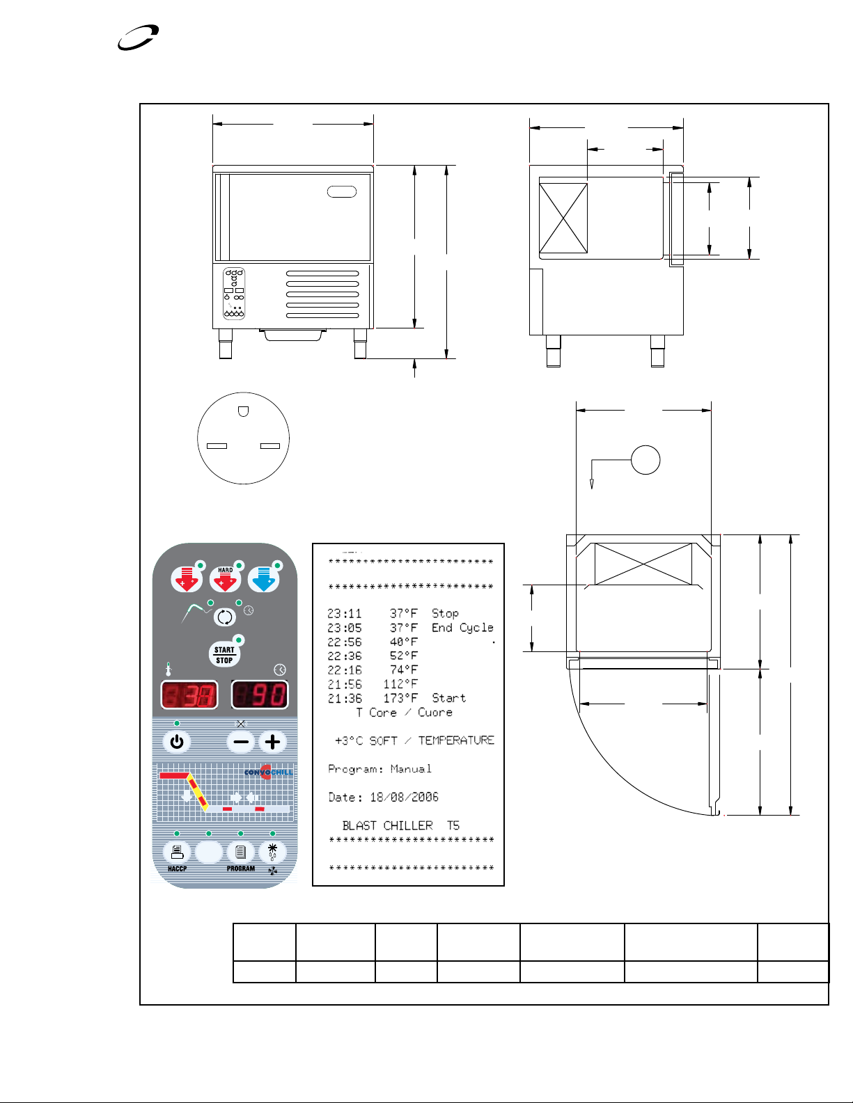
Delfield
™
®
v
v
v
v
v
v
v
!
v
v
v
v
v
v
v
by Delfield
®
38
38
0
™
'
.%-!0
!-00(!3%
v
v
v
v
v
v
v
v
v
v
v
v
T5: Blast Chiller/Shock Freezer
Sample Printout
Model Voltage Comp. H.P. Total Max Amps Max Fuse Size
Average Heat Rejected
(W)
Ship Weight
T5 220-230/1/60 .75 10.0 12.0 2,475 275
Page 24

Delfield
™
®
v
v
v
v
v
v
v
v
v
v
v
v
v
v
.%-!0
8
9
:
'
'
.%-!0
!-00(!3%
!-00(!3%
by Delfield
®
38
38
0
™
T14D: Blast Chiller/Shock Freezer
Sample Printout
Model Voltage Comp. H.P. Total Max Amps Max Fuse Size
T14D 220-230/3/60 3.0 20.0 25.0 9,900 650
Average Heat Rejected
(W)
Ship Weight
Page 25

Delfield
™
®
by Delfield
®
38
38
0
™
DRAIN
DRAIN
REFRIGERANT LINES
ELECTRICAL
DRAIN
DRAIN
DRAIN
Sample Printout
T20C: Blast Chiller/Shock Freezer
Model Voltage Max Fuse Size
Average Heat Rejected
(W)
Ship Weight
T20C 220-230/1/60 15 12895 550 lbs.
Page 26

Delfield
™
®
by Delfield
®
38
38
0
™
Drain
Drain
REFRIGERANT LINES
Drain
Drain
ELECTRICAL LINES
Drain
T24C: Blast Chiller/Shock Freezer
Sample Printout
Model Voltage Max Fuse Size
Average Heat Rejected
(W)
T24C 220-230/1/60 15 12895 550 lbs.
Ship Weight
Page 27

Delfield
™
®
by Delfield
®
38
38
0
™
REFRIGERANT & ELECTRICAL LINES
DRAIN
5.5”
REFRIGERANT & ELECTRICAL LINES
DRAIN
DRAIN
30”
5.5”
T40: Blast Chiller/Shock Freezer
Sample Printout
Model Voltage Max Fuse Size
T40 220-230/1/60 15 22330 850 lbs.
Average Heat Rejected
(W)
Ship Weight
Page 28

Delfield
™
®
39.00
39.00
39.00
Ambient Operating Limits: -20˚F to 120˚F
Note: The Deleld Blast Chiller/Shock Freezer is wired independently of the remote
condensing unit. No interconnecting wiring is required between the blast chiller
and the condensing unit. All condensing units have units have crankcase heaters.
Condensing unit control systems are provided wired from the factory. Field
Connection is made by connecting supply power to the compressor contactor.
Outdoor condensing unit applications require the use of an optional UL listed hood,
deleld P/N CUHOOD, for protection from the elements. Water cooled units are not
recommended for outdoor installation.
Interconnecting piping, curbs or other mounting methods and refrigerant are not
included. Installation must be made by a qualied refrigeration technician. Piping runs
of greater than 100 feet require consultaion with the factory.
T20C/T24C
Deleld Model#: T20-T24CU
Refrigerant 404A
Compressor and Capacity
Compressor and wiring
Condensing Unit Wiring
High Pressure Switch Set Point: 450 psig, 380 psig re-set
Control System
Compressor Reliability Crankcase Heater 65 watts
Flow Control
Optional Outdoor Hood Deleld Model Number: CUHOOD
Shipping Weight
Low pressure switch Set Point: 25psig, Range = 15in to 100psig
Oil Pressure Dierential Switch Sensotronic Oil Pressure Switch
Condenser Capacity Control Head Pressure Control Set at 84˚F, 185psig
Reciever Capacity
Accumulator Yes
Condensing Unit 500 Lbs.
Outdoor Hood 100 Lbs.
3 HP Compressor
13560 BTUH @ -32˚F, 90 amb, 104.4 Cond: 27,500BTUH
@ -5˚, 90 amb
208/230V/60Hz/3Ph
Max Fuse Size: 35A
Max Circuit Ampacity:25.4A
46lbs. @ 90% liquid refrigerant ll (31lbs. max
refrigerant charge)
T20C & T24C: Blast Chiller/Shock Freezer Remote Condensing Unit
Page 29

Delfield
™
®
T20-24CUW: Remote Water Cooled Condensing Unit
Ambient Operating Limits: 50˚F to 110˚F
Note: The Deleld Blast Chiller/Shock Freezer is wired independently of the remote
condensing unit. No interconnecting wiring is required between the blast chiller
and the condensing unit. All condensing units have units have crankcase heaters.
Condensing unit control systems are provided wired from the factory. Field
Connection is made by connecting supply power to the compressor contactor.
Outdoor condensing unit applications require the use of an optional UL listed hood,
deleld P/N CUHOOD, for protection from the elements. Water cooled units are not
recommended for outdoor installation.
Interconnecting piping, curbs or other mounting methods and refrigerant are not
included. Installation must be made by a qualied refrigeration technician. Piping runs
of greater than 100 feet require consultaion with the factory.
T20C/T24C
Deleld Model#: T20-T24CUW
Refrigerant 404A
Compressor and Capacity
Compressor and wiring
Condensing Unit Wiring
High Pressure Switch Set Point: 450 psig, 380 psig re-set
Control System
Compressor Reliability Crankcase Heater 65 watts
Flow Control
Shipping Weight Condensing Unit 600 Lbs.
Low pressure switch Set Point: 25psig, Range = 15in to 100psig
Oil Pressure Dierential Switch Sensotronic Oil Pressure Switch
Condenser Capacity Control Head Pressure Control Set at 84˚F, 185psig
Reciever
Accumulator Yes
3 HP Compressor
9,950 BTUH @ -40˚F, 85˚F inlet water, 105˚F Condensing
208/230V/60Hz/3Ph
Max Fuse Size: 35A
Man Circuit Ampacity:25.4A
46lbs. @ 90% liquid refrigerant ll (31lbs. max refrigerant
charge)
Water cooled condensing unit water usage @ 85˚F incoming
water, 105˚F (250psig) R404a condensing:
3HP Condensing Unit
Evaporating Temperature Condenser Water Usage (GPM)
-40˚F 1.8
-30˚F 2.5
-20˚F 3.2
-10˚F 4.0
0˚F 4.9
Page 30

Delfield
™
®
30.00
48.00
36.00
35.00
48.00
27.00
30.00
48.00
Ambient Operating Limits: -20˚F to 120˚F
Note: The Deleld Blast Chiller/Shock Freezer is wired independently of the remote
condensing unit. No interconnecting wiring is required between the blast chiller
and the condensing unit. All condensing units have units have crankcase heaters.
Condensing unit control systems are provided wired from the factory. Field
Connection is made by connecting supply power to the compressor contactor.
Outdoor condensing unit applications require the use of an optional UL listed hood,
deleld P/N CUHOOD, for protection from the elements. Water cooled units are not
recommended for outdoor installation.
Interconnecting piping, curbs or other mounting methods and refrigerant are not
included. Installation must be made by a qualied refrigeration technician. Piping runs
of greater than 100 feet require consultaion with the factory.
T40
Deleld Model#: T40CU
Refrigerant 404A
Compressor and Capacity
Compressor and wiring
Condensing Unit Wiring
High Pressure Switch Set Point: 450 psig, 380 psig re-set
Control System
Compressor Reliability Crankcase Heater 65 watts
Flow Control
Optional Outdoor Hood Deleld Model Number: CUHOOD
Shipping Weight
T40: Blast Chiller/Shock Freezer Remote Condensing Unit
Low pressure switch Set Point: 25psig, Range = 15in to 100psig
Oil Pressure Dierential Switch Sensotronic Oil Pressure Switch
Condenser Capacity Control Head Pressure Control Set at 84˚F, 185psig
Reciever Capacity
Accumulator 500 Cubic Inch Capacity
Oil Separator Yes
Oil Filter Yes
Condensing Unit 600 Lbs.
Outdoor Hood 100 Lbs.
6 HP Compressor
24,150 BTUH @ -32˚F, 90 amb, 102.2 Cond: 46,740BTUH
@ -5˚, 90 amb110.3 Cond.
208/230V/60Hz/3Ph
Max Fuse Size: 60A
Max Circuit Ampacity:42.3A
55.4lbs. @ 90% liquid refrigerant ll (37.5lbs. max
refrigerant charge)
Page 31

Delfield
™
®
Ambient Operating Limits: 50˚F to 110˚F
Note: The Deleld Blast Chiller/Shock Freezer is wired independently of the remote
condensing unit. No interconnecting wiring is required between the blast chiller
and the condensing unit. All condensing units have units have crankcase heaters.
Condensing unit control systems are provided wired from the factory. Field
Connection is made by connecting supply power to the compressor contactor.
Outdoor condensing unit applications require the use of an optional UL listed hood,
deleld P/N CUHOOD, for protection from the elements. Water cooled units are not
recommended for outdoor installation.
Interconnecting piping, curbs or other mounting methods and refrigerant are not
included. Installation must be made by a qualied refrigeration technician. Piping runs
of greater than 100 feet require consultaion with the factory.
T40
Deleld Model#: T40CUW
Refrigerant 404A
6 HP Compressor
Compressor and Capacity
Compressor and wiring
Condensing Unit Wiring
High Pressure Switch Set Point: 450 psig, 380 psig re-set
Control System
Compressor Reliability Crankcase Heater 65 watts
Flow Control
Optional Outdoor Hood Deleld Model Number: CUHOOD
Shipping Weight
Low pressure switch Set Point: 25psig, Range = 15in to 100psig
Oil Pressure Dierential Switch Sensotronic Oil Pressure Switch
Condenser Capacity Control Head Pressure Control Set at 84˚F, 185psig
Reciever Capcity
Accumulator 500 Cubic Inch Capacity
Oil Separator Yes
Oil Filter Yes
Condensing Unit 600 Lbs.
Outdoor Hood 100 Lbs.
24,950 BTUH 4.1gpm waterow @ -32˚F, 90 amb, 102.2
Cond: 18,090 BTUH @-40˚F, 85˚F inlet water, 105˚F
Condensing
208/230V/60Hz/3Ph
Max Fuse Size: 60A
Max Circuit Ampacity:42.3A
55.4lbs. @ 90% liquid refrigerant ll (37.5lbs. max
refrigerant charge)
T40CUW: Remote Water Cooled Condensing Unit
Water cooled condensing unit water usage @ 85˚F incoming
water, 105˚F (250psig) R404a condensing:
6HP Condensing Unit
Evaporating Temperature Condenser Water Usage (GPM)
-40˚F 3.15
-30˚F 4.1
-20˚F 5.2
-10˚F 6.4
0˚F 7.8
Page 32

T5/T14D REFRIGERATION SYSTEM SCHEMATIC
Page 33

9. WIRING DIAGRAMS
Page 34

Page 35

Page 36

Page 37

Page 38

T40 Installation and Assembly
Supplied Equipment List.
T40 Base
T40 Control Box
T40 LS Wall Panel
T40 Front Panel
with Door
T40 Back Panel
T40 Top Panel
T40 RS Wall Panel
T40 Remote Condensing Unit
T40 Air Deection
Shields
Alignment Blocks
Cam Hole Covers
Cam Lock T-Handle
Page 39

1. Position cabinet floor on a flat , le vel surface with the slotted
end facing up.
T40 Installation and Assembly
NOT E: D o no t break alignment block when placing panels in
place.
The first panel will be the left side of the unit if you are facing
the door.
NOT E: E ns ure all ca m lo ck s are in the open po si ti on b efore
placing any panels.
Make sure the skir t on the vertical panels covers
the outside of the mounting floor.
Lock bottom locking cams on
the outside of the first panel.
Insert T-handle wrench and
twist clockwise until a positive
stop is achieved.
The panel will now stand on
its own.
• Ensure the entry way is facing forw ard
(gray plastic transition piece)
• Insert one alignment b lo ck i nto the channel in bet ween each
of the locking cams.
NOT E: D o no t le an o r pu sh o n un su pp orted
panels.
3. Attach the back panel to the
mounting floor in the same manner
as the first panel. The back panel
will wrap around both sides.
NOT E: E ns ure all ca m lo ck s are in
the open position before placing
any panels.
NOT E: D o no t break alignment block when placing panels in
place.
Lock the side locking cams on the outside of the first panel
and the left side and bottom locki ng c am s on t he i ns id e of t he
back panel. Inser t T-handle wre nc h an d twist clockwise until a
positive stop is achieved.
• Attach deflector shields either side of the
first panel as shown. The deflector shields
will cover the co rners on the first panel and
are attached with provi de d sc rews.
2. Raise the first panel (with the evaporator, fans and air
channel) onto the mounting floor with the fans facing inside.
• Place bottom of the panel into th e al ignment channel on the
mounting floor for prop er p la cement, using the alignment
block to align panel.
Page 40

T40 Installation and Assembly
4. Attach the right side panel
to the mounting floor in the
same manner as the other two
panels. Lock the side locking
cams on the inside bottom
and side of the panel. Insert
T-handle wrench and twist
clockwise until a positive stop
is achieved.
NOT E: E ns ure all ca m lo ck s are in the open po si ti on b efore
placing any panels.
NOT E: D o no t break alignment block when placing panels in
place.
5. Attach the front panel
in the same manner as the
others. Front panel will
wrap around the sides.
Lock all side and bottom
cams when the panel
is in position. Insert Thandle wrench and twist
clockwise until a positive
stop is achieved.
6. Place the top panel on to the to p of t he c ab in et w it h
the refrigeration holes facing the first panel. Tread the
refrigeration pipes through the supplied holes and ensure
there is no binding.
NOT E: E ns ure all ca m lo ck s are in the open po si ti on b efore
placing any panels.
• Attach the Left side deflector shield to the front pa ne l wi th
provided scre ws. The shield should cover the corner.
Lock all side cams when the panel is in position. Insert
T-handle wrench and twist clockwise until a positive stop is
achieved.
1. Hole for Probes
2. Electrical Hole
3. Refrigerant Line Holes
7. Place the contro l pa ne l on t he outside of the top and front of
the unit. Attach with supplied screws an d sc rew holes.
Page 41

8. Thread electrical from the inside of the unit through the
supplied hole in the top. D o no t cu t an ot he r ho le t o th read
electrical.
T40 Installation and Assembly
This should be done by a qualified refrigerat io n ex pe rt.
Put the compres so r system in a suitable, well aired place no
fart he r th an 2 5 feet. from cabinet.
11. Place interior prob es
1. In teri or Probe1: Place on wall next to the evaporator
2. Food Probe: Place in food prod uc t fo r mo ni tori ng
3. In teri or Probe2: Place on opposite side of cabinet
from evaporator 3/4 of the way to the top of the
cabinet.
9. Thread electrical wires through the top of cont rol box and
connect to controls.
• Attach labeled electrical line to the corresponding labeled
connector on the control panel.
10. Pipe re mo te condensing unit to the refrigerant lines
coming out of the top of the cabinet.
12. Unit must be plumbed with a P-trap to a d rain for
evaporator water discharge.
13. Place cam plugs in all cam holes to cover them. Press until
seated in holes.
14. Install ramp and threshold onto the front o f th e ou ts id e of
the door.
Page 42

Page 43

Page 44

980 S. Isabella Rd., Mt. Pleasant, MI 48858, U.S.A. • (989) 773-7981 or (800) 733-8829 • Fax (888) 779-2040 • www.delfield.com
Delfield reserves the right to make changes in design or specifications without prior notice. ©2007 The Delfield Company. All rights reserved. Printed in the U.S.A.
Mt. Pleasant, MI Covington, TN
Thank you for choosing Delfield!
Help is a phone call away. Help our team of professional, courteous
customer service reps by having your model number and serial number
available at the time of your call (800) 733-8829.
Model: ____________________ S/N: ___________________
Installation Date: ____________
For a list of Delfield’s authorized parts depots,
visit our website at www.delfield.com.
DMCONVOCHILL 06/07
 Loading...