

Delfield N8831, N8845, N8859, N8873, N8887 Specifications
...
PROJECT _____________________________________
NOTE: NOT TO SCALE
NOTE: NOT TO SCALE
6.25"
15.9cm
9.12"
23.16cm
19.87"
50.5cm
24.67"
62.66cm
25.87"
66cm
A
A – 1.20"
A – 3.05cm
NOTE: NOT TO SCALE
11.87"
30.2cm
TYPICAL PLAN VIEW
N8700-D MODELS
TYPICAL ELEVATION VIEW
N8700-D MODELS
RIGHT END VIEW
ALL N8700-D MODELS
ITEM NUMBER_________________________________
QUANTITY _______________ DATE________________
APPROVAL____________________________________
N8700-D
Drop-In Individually-Controlled Electric Food Wells
Short Form
Specifications
Top shall be one-piece 18-gauge
stainless steel, with .60" (1.524cm)
overhang around perimeter and diestamped 19.87" x 11.87" (50.5 cm
x 30.2 cm) openings with depressed
edges. Formed well below each
opening shall be 6.25" (15.9 cm)
deep. Each well shall have an
individual infinate temperature control
and 1000 watt heating element
attached to bottom of well. Unit is
equipped with .5" drains, (one per
well located in right rear corner
.5" female N.P.T.) manifold and .5"
ball valve. Exterior housing shall be
20-gauge galvanized steel. Unit shall
be insulated on sides and between
wells with 1.00" (2.5 cm) fiberglass;
bottom shall have 2.00" (5.1 cm)
blanket insulation.
Unit shall have all individual controls
wired to a control panel for mounting
in counter or at a remote location; 4'
(1.2 m) length of wiring and conduit
are provided. Unit shall have a threewire electrical junction box to allow
hard-wiring at installation.
Optional Accessories and
Modifications:
• Adapter plates and bars
• Single- or double-service flip-up
sneezeguards
• Telescoping covers
• Omit drains and manifold
Model N8787-D
Mechanical Data — Standard Unit
MODEL COUNTER CUTOUT CONTROL PANEL # OF VOLTS/HERTZ/ SHIP
NUMBER A DIMENSIONS CUTOUT DIMENSIONS FOOD WELLS PHASE AMPS WEIGHT
17.88” (45.4cm) 16.88” X 25” (37.8cm x 58.4cm) 4.62” x 7” (11.7cm x 17.8cm) 1 115/60/1 8.3 39 lbs/ 17 kg
N8717-D
N8731-D
N8745-D
N8759-D
N8773-D
N8787-D
The Delfield Company, 980 S. Isabella Rd., Mt. Pleasant, MI 48858, U.S.A. • (800) 733-8821 • Fax (800) 669-0619 • www.delfield.com
Delfield reserves the right to make changes in design or specifications without prior notice. ©2002 The Delfield Company. All rights reserved. Printed in U.S.A.
31.75” (80.6cm) 30.75” x 25” (73cm x 58.4cm) 4.62” x 10.31” (11.7cm x 26.2cm) 2 115/60/1 17.0 119 lbs/ 54 kg
45.63” (115.9cm) 44.63” x 25” (108.3cm x 58.4cm) 4.62” x 14.5” (11.7cm x 36.8cm) 3 208-230/60/1 15.7 150 lbs/ 68 kg
59.5” (151.1cm) 58.5” x 25” (143.5cm x 58.4cm) 4.62” x 18.69” (11.7cm x 47.5cm) 4 208-230/60/1 20.9 170 lbs/ 77 kg
73.38” (186.4cm) 72.38” x 25” (178.8cm x 58.4cm) 4.62” x 22.88” (11.7cm x 58.1cm) 5 208-230/60/1 26.1 196 lbs/ 88 kg
87.25” (221.4cm) 86.25” x 25” (214cm x 58.4cm) 4.62” x 27” (11.7cm x 68.6cm) 6 208-230/60/1 31.3 232 lbs/ 104 kg
19.87"
50.5cm
24.5"
62.23cm
25.87"
65.71cm
A
A – 1.31"
A – 3.33cm
A – 6"
A – 15.2cm
C
L
8.00"
20.3 cm
B
NOTE: NOT TO SCALE
NOTE: NOT TO SCALE
8"
20.3cm
11"
27.9cm
NOTE: NOT TO SCALE
CONTROL PANEL CUTOUT DIMENSION:
4.62" x 6.00" (11.7 cm x 15.2 cm)
8"
20.3cm
TYPICAL PLAN VIEW
N8800 MODELS
TYPICAL ELEVATION VIEW
N8800 MODELS
RIGHT END VIEW
ALL N8800 MODELS
PROJECT _____________________________________
ITEM NUMBER_________________________________
QUANTITY _______________ DATE________________
APPROVAL____________________________________
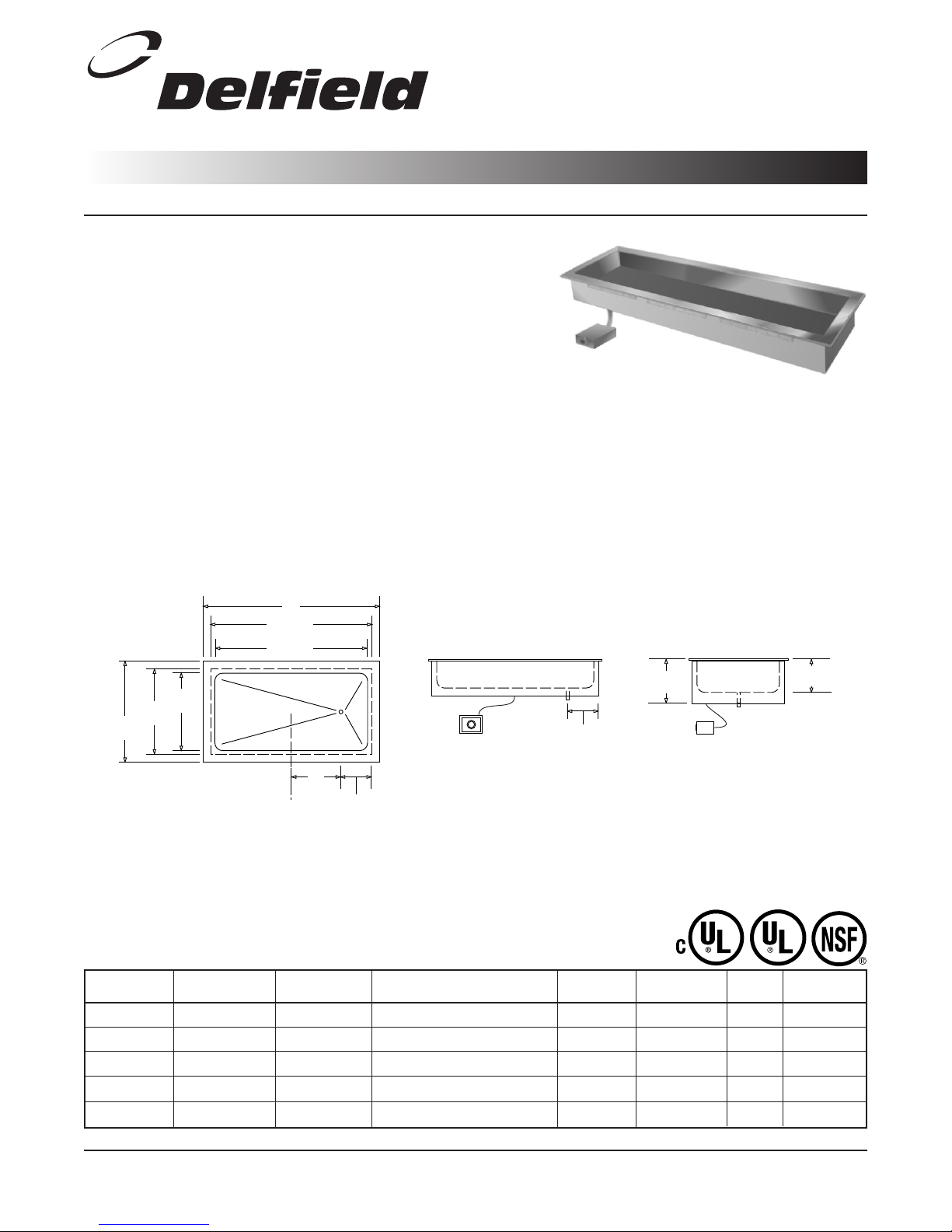
N8800
Drop-In Single-Tank Electric Hot Food Wells
Short Form
Specifications
Top shall be one-piece 18-gauge stain-
less steel, with .60" (1.524 cm) overhang around perimeter. Well shall be
8.00" (20.3 cm) deep, creased to a
1.00" male N.P.T. stainless steel drain.
Unit shall be provided with adapter
bars to allow placement of 12" x 20"
(30.5 cm x 50.8 cm) pans. Unit shall
have the same number of 1000 watt
heating elements as the unit’s 12" x
20" pan capacity, mounted on underside of well. Sides shall be insulated
with 1.00" (2.5 cm) fiberglass; bottom
shall have 2.00" (5.1 cm) blanket
insulation. Exterior housing shall be
20-gauge galvanized steel.
Unit shall have a single thermostat
wired to a control panel for mounting
in counter or at a remote location; 2'
(0.6 m) length of wiring and conduit
are provided. Unit shall have a threewire electrical junction box to allow
hard-wiring at installation.
Optional Accessories and
Modifications:
• Adapter plates and bars
• Single- or double-service flip-up
sneezeguards
• Telescoping covers
Model N8887
Mechanical Data — Standard Unit
MODEL COUNTER CUTOUT # OF 12” X 20” VOLTS/HERTZ/ SHIP WEIGHT
NUMBER A B DIMENSIONS PANS HELD PHASE AMPS LBS/KG
N8831
N8845
N8859
N8873
N8887
The Delfield Company, 980 S. Isabella Rd., Mt. Pleasant, MI 48858, U.S.A. • (800) 733-8821 • Fax (800) 669-0619 • www.delfield.com
Delfield reserves the right to make changes in design or specifications without prior notice. ©2002 The Delfield Company. All rights reserved. Printed in U.S.A.
31.75” (80.6cm) 5.91” (15cm) 30.75” X 25” (73cm x 58.4cm) 2 120/60/1 17.0 124/56
45.63” (115.9cm) 12.84” (32.6cm) 44.63” x 25” (108.3cm x 58.4cm) 3 208-230/60/1 14.4/15.9 150/68
59.5” (151.1cm) 19.78” (50.2cm) 58.5” x 25” (143.5cm x 58.4cm) 4 208-230/60/1 19.2/21.3 189/85
73.38” (186.4cm) 26.71” (67.8cm) 72.38” x 25” (183.8cm x 63.5cm) 5 208-230/60/1 24.0/26.6 200/91
87.25 (221.6cm) 33.65” (85.5cm) 86.25” x 25” (214cm x 58.4cm) 6 208-230/60/1 28.8/31.3 226/102
DS87_8800 01/02
 Loading...