

Delfield MFSC-31, N14-1313-34, N10-1313-34, N10-1313-37, N14-1313-37 Service And Installation Manual
...Page 1
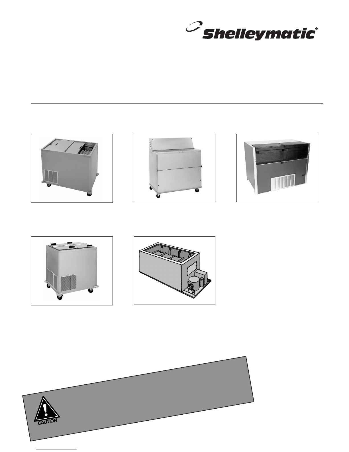
Milk, Ice Cream and Milk & Ice Cream Dispensers
Service and Installation Manual
Please read this manual completely before attempting to install or operate this equipment! Notify carrier of damage! Inspect all
components immediately. See page 2.
N, N6/N10/N14
Free-standing milk or
beverage dispensers
NSCF, SCF
Free-standing ice cream
dispensers and milk & ice
cream dispensers
NDF
Free-standing milk or
beverage dispensers
MF, MFSC, FF,
FFSC, RFF, RFFSC
Built-in milk or beverage,
ice cream, and milk & ice cream
dispensers
NLFAC
Free-standing milk or beverage
dispensers with air curtain
IMPORTANT INFORMATION
READ BEFORE USE
PLEASE SAVE THESE INSTRUCTIONS!
Effective June 2003
Page 2

Milk, Ice Cream & Milk & Ice Cream Dispensers Service and Installation Manual
Milk, Ice Cream & Milk & Ice Cream Dispensers Service and Installation Manual
3
For customer service, call (800) 733-8829, (800) 773-8821, Fax (989) 773-3210, www.deleld.com
CONTENTS
SERIAL NUMBER LOCATION ....................................................2
RECEIVING & INSPECTING EQUIPMENT .................................2
SPECIFICATIONS........................................................................3
REFRIGERANT NOTES...............................................................3
INSTALLATION........................................................................4-5
OPERATION................................................................................6
MAINTENANCE ..........................................................................7
WIRING DIAGRAM ....................................................................8
REPLACEMENT PARTS LISTS..............................................9-10
STANDARD LABOR GUIDELINES............................................11
STANDARD WARRANTIES .................................................12-13
AUTHORIZED PARTS DEPOTS...................................back cover
©2003 The Delfield Company. All rights reserved. Reproduction
without written permission is prohibited. “Delfield” and “Shelleymatic” are
registered trademarks of The Delfield Company.
SERIAL NUMBER LOCATION
Serial number tag locations
MF/MFSC, FF/FFSC and RFF/RFFSC — on the end above the
refrigeration system.
N, N6/N10/N14, and SCF — rear of the unit above the louver.
NDF — Front right hand corner under the lid.
NLFAC — at the rear of the unit by the power cord.
Always have the serial number of your unit available when
calling for parts or service. A complete list of authorized
Delfield parts depots is shown on the back cover of this
manual.
The units represented in this manual are for indoor use only.
RECEIVING AND INSPECTING THE EQUIPMENT
Even though most equipment is shipped crated, care should
be taken during unloading so the equipment is not damaged
while being moved into the building.
1. Visually inspect the exterior of the package and skid or
container. Any damage should be noted and reported
to the delivering carrier immediately.
2. If damaged, open and inspect the contents with the
carrier.
3. In the event that the exterior is not damaged, yet upon
opening, there is concealed damage to the equipment
notify the carrier. Notification should be made verbally
as well as in written form.
4. Request an inspection by the shipping company of the
damaged equipment. This should be done within 10
days from receipt of the equipment.
5. Check the lower portion of the unit to be sure casters
are not bent.
6. Also open the compressor compartment housing and
visually inspect the refrigeration package. Be sure lines
are secure and base is still intact.
7. Freight carriers can supply the necessary damage forms
upon request.
8. Retain all crating material until an inspection has been
made or waived.
Uncrating the Equipment
First cut and remove the banding from around the crate.
Remove the front of the crate material, use of some tools will
be required. If the unit is on legs remove the top of the crate
as well and lift the unit off the skid. If the unit is on casters
it can be rolled off the skid.
2
For customer service, call (800) 733-8829, (800) 773-8821, Fax (989) 773-3210, www.deleld.com
Page 3
SPECIFICATIONS
Milk, Ice Cream & Milk & Ice Cream Dispensers Service and Installation Manual
MODEL LOADING/ AMPS NEMA BTU REF
NUMBER H.P. DISPENSING (115V) PLUG LOAD CAP. CHG.
Self-cont. free-standing milk or beverage dispensers
N-520 1/4 sliding top lids 5.0 5-15P 189 1035 16oz
N-860 1/4 sliding top lids 5.0 5-15P 259 1167 16oz
N-1200 1/4 sliding top lids 5.0 5-15P 328 1273 16oz
N-1530 1/4 sliding top lids 5.0 5-15P 398 1360 16oz
N6-1313-33 1/4 sliding top lids 5.0 5-15P 245 1167 16oz
N6-1313-37 1/4 sliding top lids 5.0 5-15P 245 1167 16oz
N10-1313-33 1/4 sliding top lids 5.0 5-15P 353 1315 16oz
N10-1313-37 1/4 sliding top lids 5.0 5-15P 353 1315 16oz
N14-1313-33 1/4 sliding top lids 5.0 5-15P 455 1422 16oz
N14-1313-37 1/4 sliding top lids 5.0 5-15P 455 1422 16oz
Self-cont. free-standing milk or beverage dispensers
NDF-12 1/4 drop front & flip top lids 5.0 5-15P 687 1204 16oz
NDF-18 1/3 drop front & flip top lids 7.0 5-15P 898 1585 24oz
Self-cont. free-standing milk or beverage dispensers with air curtain (BTU is with
lids closed.)
NLFAC-8 1/3 hinged lids w/air curtain 7.0 5-15P 668 2184 24oz
NLFAC-12 1/2 hinged lids w/air curtain 9.0 5-15P 859 2885 32oz
NLFAC-16 1/2 hinged lids w/air curtain 9.0 5-15P 1050 3193 32oz
MODEL LOADING/DISPENSING AMPS NEMA BTU REF
NUMBER H.P. BODY STYLE (115V) PLUG LOAD CAP. CHG.
Self-cont. free-standing milk and ice cream dispensers
NSCF-48 1/4 hinged top lids 6.0 5-15P 139(ref) 1596(ref) 16oz
414(frz) 796(frz)
Self-cont. free-standing ice cream dispensers
SCF-32 1/4 hinged top lids 6.0 5-15P 709 915 16oz
SCF-48 1/3 hinged top lids 8.0 5-15P 1043 1350 24oz
MODEL CUTOUT AMPS NEMA BTU REF
NUMBER H.P. DIM. (L X D) (115V) PLUG LOAD CHARGE CHG
Self-cont. built-in milk or beverage dispensers *a 2.87” space is required between each cutout
MFSC-2020 1/4 (1) 25” x 22.25” 6.5 5-15P 304 1223 16oz
MFSC-2821 1/4 (1) 10.75” x 21” 6.5 5-15P 264 1166 16oz
MFSC-31 1/4 (2) 10.75” x 21”* 6.5 5-15P 296 1212 16oz
MFSC-44 1/4 (3) 10.75” x 21”* 6.5 5-15P 408 1346 16oz
MFSC-57 1/4 (4) 10.75” x 21”* 6.5 5-15P 519 1447 16oz
MODEL RECOMMENDED CUTOUT BTU
NUMBER H.P. DIMENSIONS (L X D) LOAD
Remote built-in milk or beverage dispensers *a 2.87” space is required between each cutout
MF-2020 1/4 (1) 25.25” x 22.25” 300
MF-2821 1/4 (1) 10.75” x 21” 260
MF-31 1/4 (2)10.75” x 21”* 300
MF-44 1/4 (3)10.75” x 21”* 410
MF-57 1/4 (4) 10.75” x 21”* 520
Remote built-in ice cream dispensers *a 2.87” space is required between each cutout
FF-3324 1/4 (1) 10.75” x 21” 430
FF-2 1/3 (2)10.75” x 21”* 710
MODEL CUTOUT AMPS NEMA BTU REF
NUMBER H.P. DIMENSIONS (L X D) (115V) PLUG LOAD CAP. CHG.
Self-cont. built-in ice cream dispensers *a 2.87” space is required between each cutout
FFSC-3324 1/4 (1) 10.75” x 21” 6.0 5-15P 434 763 16oz
FFSC-2 1/3 (2) 10.75” x 21”* 8.0 5-15P 709 915 24oz
Self-cont. built-in milk & ice cream dispensers *a 2.87” space is required between each cutout
RFFSC-103 1/4 (2) 10.75” x 21”* 6.0 5-15P 139(ref) 1596(ref)
414(frz) 796(frz)
MODEL RECOMMENDED CUTOUT BTU LOAD
NUMBER H.P. DIMENSIONS (L X D) REFG. FRZ.
Remote built-in milk & ice cream dispensers *a 2.87” space is required between each cutout
RFF-103 1/3 (2) 10.75” x 21” 140 410
REFRIGERANT NOTES
MF, MFSC, N, N6/N10/N14, NDF and
NLFAC series refrigerators use HFC-134a
refrigerant.
FF, FFSC, RFF, RFFSC, SCF, and NSCF
freezers use HFC-404A refrigerant.
For customer service, call (800) 733-8829, (800) 773-8821, Fax (989) 773-3210, www.deleld.com
3
Page 4

Milk, Ice Cream & Milk & Ice Cream Dispensers Service and Installation Manual
Milk, Ice Cream & Milk & Ice Cream Dispensers Service and Installation Manual
5
For customer service, call (800) 733-8829, (800) 773-8821, Fax (989) 773-3210, www.deleld.com
INSTALLATION
Location
Be sure the location chosen has a floor strong enough to
support the total weight of the cabinet and contents. Units in
this product line can weigh as much as 1500 pounds when it
is fully stocked. Reinforce the floor as necessary to provide for
maximum loading.
For the most efficient refrigeration, be sure to provide good air
circulation inside and out.
Inside cabinet: Do not pack unit so full that air cannot circulate.
Take care not to block air flow to the fans and allow space
along sides.
Outside cabinet: Be sure that the unit has access to ample
air. Avoid hot corners and locations near stoves and ovens.
It is recommended that the rear of the unit be no less than
two inches from any wall, partition or any other object which
will restrict exhaust air flow.
Leveling
A level cabinet looks better and will perform better because
the cabinet will not be subject to unnecessary strain due to
doors not properly lining up with door frames.
Some models have casters for ease of cleaning underneath
and for mobility. It is important that the unit be installed in a
stable condition with the front casters locked before operating.
Locking the front casters after installation is the owner’s and
operator’s responsibility.
Electrical connection
A standard self-contained unit is provided with a power cord
and three-prong grounded plug.
The unit should be plugged into a receptacle with its own
circuit protection that matches the amperage of the plug.
Refer to the amperage data on page three or the
serial tag data and your local code or the National
Electrical Code to be sure the unit is connected
to the proper power source. A protected circuit of
the correct voltage and amperage must be run for
connection to the unit.
The power supply must be disconnected
whenever performing maintenance or repairing
the equipment!
The unit must never be operated without the
louvered panel in place.
Built-in units
All self-contained units (MFSC, FFSC and RFFSC) are tested
at the factory to assure proper operation. The unit should not
be installed directly next to high heat generating equipment
(ranges, griddles, etc.).
These units are built into the counter from below and must
be supported from the bottom. The counter cut-out sizes and
power supply requirements are shown in the specifications on
page three. All refrigerators have drains located in the bottom
of the tank. An appropriate drainage area or container must
be provided by the customer. Be sure to place the unit so the
pressure control, located near the compressor, can be reached.
For installation of remote units (MF ,FF and RFF), consult a
refrigeration service company to connect refrigeration lines to
the remote condensing unit.
Self-contained refrigerated units (MFSC, FFSC
and RFFSC) require air flow to the compressor.
A louver is provided and must be installed in the
counter in front of the condenser. An equal size
opening at the rear of the cabinet must also be
provided to allow warm air to escape. Failure to
do so will void all product warranties.
Free standing units
All self-contained units (N, N6/10/14, NDF, NLFAC, SCF and
NSCF) are tested at the factory to assure proper operation. The
unit should not be installed directly next to high heat generating
equipment (ranges, griddles, etc.).
These units are free standing, either on legs or casters. The
power supply requirements are shown on page three. All free
standing units have drains located in the bottom of the tank.
An appropriate drainage area or container must be provided by
the customer.
Do not place the unit against a wall or any object that will
block air circulation through the condensing unit. If the unit
must be placed against a wall, leave a minimum of 2” of
space for air flow.
4
For customer service, call (800) 733-8829, (800) 773-8821, Fax (989) 773-3210, www.deleld.com
Page 5
Milk, Ice Cream & Milk & Ice Cream Dispensers Service and Installation Manual
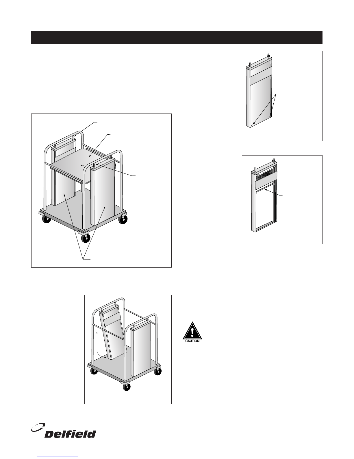
RETAINER
LO
AD TRAY
ELEVATOR HOUSINGS
RETAINER
REMOVE SCREWS,
SLIDE COVER OFF
REMOVE OR
ADD SPRINGS
AS NEEDED
INSTALLATION CONTINUED
How to adjust self-leveling dispenser
Tools Needed: One small flat head screw driver; One Phillips
head screw driver.
1. Always wear safety glasses when adjusting your dispenser.
Also, lock brakes on mobile units before beginning.
2. Unload dispenser and remove stainless steel load tray by
lifting straight up and set it aside (see fig. 1).
(figure 1) Sample unit
3. Use small regular screw driver to loosen each retainer
mounted on stainless steel rod at top of each elevator
housing.
4. To remove
elevator housing,
lift housing
straight up to
clear the stud on
unit base. Then
gently swing the
bottom of the
housing towards
the inside of the
unit and pull
housing out of
the unit (see fig.
2). Lay housing
on flat surface.
(figure 2) Remove elevator housing
5. Use Phillips head
screw driver to
remove front panel
on the elevator
housing (see fig. 3).
6. If carrier is riding
too high, you need
to remove springs.
With carrier all the
way to the top,
gently disengage
one spring at a
time, unhooking
(figure 3) Remove front panel
bottom loop out of
carrier bracket (see
fig. 4). Remove as
many springs as
necessary.
If carrier is riding too
low, you need to add
springs. With carrier
all the way to the top,
gently engage one
spring at a time by
hooking bottom loop
of spring into carrier
bracket. Add as many
(figure 4) Remove or add springs
springs as necessary.
7. When finished, put elevator housing back in unit and put
stainless steel load tray back on elevator housings. Load
unit to test dispensing level. If spring adjustment does
not position carrier properly, repeat procedure #6 trying
different springs. If this does not work, a different set
of springs may be required. To order, call The Delfield
Company Parts and Service Department at 800.733.8829
8. If level is appropriate, put front panels back on and
tighten retainer.
CAUTION: Dispenser should not be operated
with front panels off elevator housing.
NOTE: When adjusting the elevators make sure each have the
same number and size of springs connected to the carrier on
both sides. This will prevent the load tray from binding.
For customer service, call (800) 733-8829, (800) 773-8821, Fax (989) 773-3210, www.deleld.com
5
Page 6
Milk, Ice Cream & Milk & Ice Cream Dispensers Service and Installation Manual
Milk, Ice Cream & Milk & Ice Cream Dispensers Service and Installation Manual
7
For customer service, call (800) 733-8829, (800) 773-8821, Fax (989) 773-3210, www.deleld.com
OPERATION: N, N6/10/14, NDF, NLFAC, MF & MFSC SERIES
N, N6/10/14, NDF, NLFAC and MFSC Series milk
dispensers are set at the factory to maintain temperatures
between 36°F and 40°F. No further adjustment should be
necessary. To begin operation on self-contained models,
plug the electrical supply cord into a receptacle with the
correct voltage. Remote models will require a connection to
a separate refrigeration system.
Loading: N, MF & MFSC Series
To load, place a complete layer of cartons or bottles
standing upright on the load tray. Then place a divider tray
on top of this layer, then another layer of cartons or bottles
on this tray, then another tray and another layer, etc. As
each additional tray is loaded, the elevators gradually lower.
The last layer may be placed on top without the use of
another tray. When loading the average tall half pint bottles,
four layers may be loaded into each compartment standing
upright and the fifth layer laying down.
It is very important to use the divider trays
provided between each successive layer of
contents to assure the correct balance of the
load and the proper action of the elevating
mechanism.
Wire racks, when used, should be loaded completely. When
placing one rack on top of the other, be sure the stacking
lugs are properly aligned.
Loading: N6/10/14 Series
These cabinets are designed to dispense 13” x 13” x 11”
high (maximum dimensions) dairy cases. Place one case
loaded with milk on the carrier and then place a second case
loaded with milk on top of the first case. Press down on
the cases leaning them toward the retaining bracket located
under the top lid track, then gradually release pressure on
the cases so that the top edge of the case engages with the
retaining bracket.
The elevating mechanism is designed to keep the contents
several inches below the top of the cabinet when fully loaded.
This distance serves two purposes:
A. It keeps the top layer of milk completely refrigerated even
when the lids are removed.
B. It insures that the lids will operate without striking the
contents as successive layers are added.
Loading: NDF Series
These cabinets are designed to dispense 13” x 13” x 11”
high (maximum dimensions) dairy cases. They do not have
a self-leveling mechanism. Simply place the cases on top of
each other inside the cabinet through the wide opening in the
top and front.
Loading: NLFAC Series
These cabinets are designed to dispense 13” x 13” x 11”
high (maximum dimensions) dairy cases. Model NLFAC-8
holds eight cases; four on the bottom and four on the top.
Model NLFAC-12 holds twelve cases; six on the bottom and
six on the top. Model NLFAC-16 holds sixteen cases, eight on
the bottom and eight on the top.
Milk cases are loaded through the wide opening in the top
and front of the unit. Fold the hinged lids up and back and
rest them on the top. The cabinet interior has self-locating
guides installed to make loading easy.
OPERATION: FFSC, RFFSC, SCF & NSCF SERIES
FFSC and SCF Series ice cream dispensers are set at the
factory to maintain temperatures between -5°F and 0°F.
RFFSC and NSCF Series combination milk and ice cream
dispensers are set at the factory to maintain temperatures
between 36°F and 40°F for refrigerated product and between
-5°F and 0°F for frozen product. Each combination unit is
constructed with two tanks and separate controls. No further
adjustments should be necessary. To begin operation plug
the electrical supply cord into a receptacle with the correct
voltage.
6
For customer service, call (800) 733-8829, (800) 773-8821, Fax (989) 773-3210, www.deleld.com
Loading
To load, place two layers of ice cream on the load tray,
then a tray, two additional layers of ice cream, then another
tray, etc. Do not stack ice cream above the frost line on
the interior of the freezer. See the instructions for the MF
units (above) for loading the refrigerated portion of the
combination units.
Page 7

Milk, Ice Cream & Milk & Ice Cream Dispensers Service and Installation Manual
MAINTENANCE
Cleaning the unit
The interior and exterior can be cleaned using soap and
warm water. If this is not sufficient, try ammonia and water
or a non-abrasive liquid cleaner.
The lid and lid openings should be cleaned with a sponge
and mild soap solution on a daily basis to maintain their
ability to seal.
When cleaning the exterior, always rub with
the “grain” of the stainless steel to avoid
marring the finish. Do not use an abrasive
cleaner because it will scratch the stainless
steel and plastic.
Do not use a sharp tool or knife to scrape any
gaskets as this may tear the gasket and ruin its
ability to seal.
Do not use full strength degreasing agents on
the gaskets as they could cause the gasket to
crack and become brittle.
The inside wall of these units house the
evaporator coil (cooling coil). Never use a
sharp object to remove frost or ice as this may
cause the unit to lose its freon charge and will
void all warranties.
Cleaning the NLFAC milk dispensers
The following special instructions apply to the model NLFAC
dispenser only. After cleaning the interior and exterior as
described above, be sure to return the milk case loading
tray to the bottom of the unit. The load tray is required
not only for easy self-locating of milk cases, but it also
ensures proper air flow through the evaporator coil for the
air curtain.
Any restriction to the air flow path, including
leaving the milk case load tray out of the
cabinet, will result in the voiding of your
warranties.
A drain is supplied to simplify cleaning of the interior.
Open the clamp used to close off the drain tube. Drain
accumulated liquid from the cabinet. Be sure to re-clamp
the tubing before resuming operation of the NLFAC unit.
Honeycomb Cleaning Procedure
Remove the honeycomb material from the equipment.
Soak in fresh hot dishwater for five minutes. Rinse by
spraying soap off with warm water, directing the spray into
the holes. Repeat rinsing steps until material is visibly
clean. Soak in sanitizing solution for five minutes. Replace
into equipment.
Cleaning the condenser
To maintain peak refrigeration performance, the
condenser coil fins must be cleaned of dust,
grease and food particles every 60 days.
If conditions are such that the condenser is totally blocked in
two months, the frequency of cleaning should be increased.
The condenser can be cleaned with a stiff brush or vacuum
cleaner. Using high pressure such as compressed air is
recommended to thoroughly clean the coil.
Failure to follow the recommended methods and
frequency of condenser coil cleaning will result
in reduced refrigeration efficiency and possible
damage to the equipment. It may also invalidate
your warranties.
Low pressure control settings
The factory recommended low pressure control settings
for using HFC-134a refrigerant are 30 psig cut-in with a 20
psig differential. For units using HFC-404A refrigerant, the
pressure control settings are 30 psig cut-in with a 25 psig
differential.
The temperature is controlled by an adjustable pressure
control located in the machine compartment. An adjustable
control has the word COLDER near the knob, with an arrow
to indicate the adjustment direction. These controls are
field adjustable and do not require a service agent. If you
have any questions, feel free to contact the Delfield Service
Department.
In attempting to adjust the pressure control, you can
do damage to your unit by accidentally adjusting the
differential. Please make small incremental adjustments
if a temperature adjustment is necessary, please contact
the service department at Delfield (800) 733-8829 #1, or
your local
service agent.
Delfield is not
responsible
for charges
incurred
while having
the pressure
control
adjusted.
Defrosting
If there is 3/8” accumulation of ice formation on the interior
wall, the unit must be turned off to defrost.
For customer service, call (800) 733-8829, (800) 773-8821, Fax (989) 773-3210, www.deleld.com
7
Page 8

Milk, Ice Cream & Milk & Ice Cream Dispensers Service and Installation Manual
Milk, Ice Cream & Milk & Ice Cream Dispensers Service and Installation Manual
9
For customer service, call (800) 733-8829, (800) 773-8821, Fax (989) 773-3210, www.deleld.com
G
N
L1
PRESSURE CONTROL
CONDENSING UNIT
MODELS — MFSC, & RFFSC
G
N
L1
PRESSURE CONTROL
CONDENSING UNIT
MODELS — N, SCF, NSCF, & NDF
ON/OFF SWITCH
MODEL —NLFAC
L1 N G
DT1 CONDENSING UNIT
THERMOSTAT
EVAP. FANS
DEFROST TIMER
WIRING DIAGRAMS
8
For customer service, call (800) 733-8829, (800) 773-8821, Fax (989) 773-3210, www.deleld.com
Page 9

Milk, Ice Cream & Milk & Ice Cream Dispensers Service and Installation Manual
PARTS REPLACEMENT
MFSC-2020
Plastic drain 3324242
1” rubber drain stopper 3234021
Lrg. elevator assy 0201737
Bearing 6320007
Extension spring .58 lbs 6150201
Extension spring .28 lbs 6150202
Retainer 6530024
Carrier 0047745
Throat collar 0044074
Lid assy 0201525
Hinge #1 extruded 6230109
Plastic hinge insert 6230110
Top lid assy 0047769
Exp. valve 3516062
Exp. valve cover 0052417
Cond. unit 3526674
Filter dryer 3516101
Pressure control 2193927
Louver 2214110003
Cord/plug assy. 2183348
MFSC-2821, MFSC-31, MFSC-44,
MFSC-57
Plastic drain 3234242
1” rubber drain stopper 3234021
Small elevator assy. 0201768
Bearing 6320007
Small elevator plate carrier 0048574
Extension spring .58 lbs 6150201
Retainer 6530024
Carrier 0048347
Large drip proof lid 3234188
Throat collar 6700029
Divider tray 0040006
Cond. unit 3526674
Filter dryer 3516101
Pressure control 2193927
Exp. valve 3516062
Exp. valve cover 0052417
Louver 2214110003
Cord/plug assy. 2183348
MF-2020
Plastic drain 3234242
1” rubber drain stopper 3234021
Large elevator assy. 0201737
Bearing 6320007
Extension spring .58 lbs 6150201
Extension spring .28 lbs 6150202
Retainer 6530024
Carrier 0047745
Throat collar 0044074
Lid assy. 0201525
Extruded hinge 6230109
Plastic hinge 6230110
Exp. valve 3516062
Exp. valve cover 0052417
MF-2821, MF-31, MF-44, MF-57
Plastic drain 3234242
1” rubber drain stopper 3234021
Small elevator assy. 0201768
Bearing 6320007
Extension spring .58 lbs 6150201
Retainer 6530024
Carrier 0048347
Large drip proof lid 3234188
Throat collar 6700029
Divider tray 0040006
Exp. valve 3516062
Exp. valve cover 0052417
FFSC-3324
Plastic drain 3234242
1” rubber drain stopper 3234021
Small elevator assy. 0201768
Bearing 6320007
Extension spring .58 lbs 6150201
Retainer 6530024
Carrier 0048347
Large drip proof lid 3234188
Throat collar 6700029
Divider tray 0040006
Cond. unit 3526709
Filter dryer 3516101
Pressure control 2193927
Exp. valve 3516273
Exp. valve cover 0051417
Louver 2214110003
Cord/plug assy. 2183348
FFSC-2
Plastic drain 3234242
1” rubber drain stopper 3234021
Small elevator assy. 0201768
Bearing 6320007
Extension spring .58 lbs 6150201
Retainer 6530024
Carrier 0048347
Large drip proof lid 3234188
Throat collar 6700029
Divider tray 0040006
Cond. unit 3526710
Filter dryer 3516101
Pressure control 2193927
Exp. valve 3516273
Exp. valve cover 0051417
Louver 2214110003
Cord/Plug Assy. 2183348
FF-3324
Plastic drain 3234242
1” rubber drain stopper 3234021
Small elevator assy. 0201768
Bearing 6320007
Extension spring .58 lbs 6150201
Retainer 6530024
Carrier 0048347
Large drip proof lid 3234188
Throat collar 6700029
Divider tray 0040006
Exp. valve 3516273
Exp. valve cover 0051417
FF-2
Plastic drain 3234242
1” rubber drain stopper 3234021
Small elevator assy. 0201768
Bearing 6320007
Extension spring .58 lbs 6150201
Retainer 6530024
Carrier 0048347
Large drip proof lid 3234188
Throat collar 6700029
Divider tray 0040006
Exp. valve 3516273
Exp. valve cover 0051417
RFFSC-103
Plastic drain 3234242
1” rubber drain stopper 3234021
Small elevator assy. 0201768
Bearing 6320007
Extension spring .58 lbs 6150201
Retainer 6530024
Carrier 0048347
Large drip proof lid 3234188
Throat collar 6700029
Divider tray 0040006
Cond. unit 3526709
Filter dryer 3516101
Pressure control 2193927
Exp. valve 1/4 low 3516225
Exp. valve 1/4 hi 3516273
Exp. valve cover 1701278
Louver 2214110003
EPR valve 3/8 inlet/outlet 3516265
Cord/Plug Assy. 2183348
RFF-103
Plastic drain 3234242
1” rubber drain stopper 3234021
Small elevator assy. 0201768
Bearing 6320007
Extension spring .58 lbs 6150201
Retainer 6530024
Carrier 0048347
Large drip proof lid 3234188
Throat collar 6700029
Divider tray 0040006
Exp. valve 1/4 low 3516225
Exp. valve 1/4 hi 3516273
Exp. valve cover 0052417
N520, N860, N1200
1” plastic drain 3234242
Cond. unit 3526674
Filter dryer 3516101
Pressure control 2193927
Exp. valve 3516062
Sensing blub holding clip 3516205
Top sliding lid assy. 0201316
4” chrome lift cover handle 3234110
Bottom sliding lid assy. 0201317
Louver 9 x 13.50 0048864
Louver 13 x 25 221411003
N-series carrier 0047121
N-series divider tray 0040005
Elevator assy. 0201768
Bearing 6320007
Ext. spring 6150201
Retainer 6230024
Elevator assy. Frzr 0201770
Louver side 13 x 13.50 0047033
Rocker switch 2190154
6” leg with remov. foot 3234645
Cord/plug assy. 2183348
3/4 valve drain 6690493
N-1530
1” plastic drain 3234242
Cond. unit 3526674
Filter dryer 3516101
Pressure control 2193927
Exp. valve 3516062
Sensing blub holding clip 3516205
Top sliding lid assy. 0201318
4” chrome lift cover handle 3234110
Bottom sliding lid assy. 0201319
Louver 9 x 13.50 0048864
Louver 13 x 25 221411003
N-series divider tray 0040005
Bearing 6320007
Ext. spring 6150201
Retainer 6230024
Sliding lid assy bottom 0201317
4” chrome lift cover handle 3234110
Louver side 13 x 13.50 0047033
Rocker switch 2190154
6” leg with remov. foot 3234645
Cord/plug assy. 2183348
3/4 valve drain 6690493
N-6-1313-37, N6-1313-34
1” plastic drain 3234242
Cond. unit 3526674
Filter dryer 3516101
Pressure control 2193927
Exp. valve 3516062
Sensing blub holding clip 3516205
Sliding lid track 6230016
Lid assy bottom 0201331
Lid assy top 0201330
Louver 13 x 13.50 0047033
Louver side 9 x 13.50 0048864
Louver 13 x 25 221411003
Milk crate carrier 0047906
Elevator assy. 0201764
Bearing 6320007
Ext. spring 6150201
Retainer 6230024
Rocker switch 2190154
6” leg with remov. foot 3234645
Cord/plug assy. 2183348
3/4 valve drain 6690493
N-10-1313-34, N-10-1313-37
1” plastic drain 3234242
Cond. unit 3526674
Filter dryer 3516101
Pressure control 2193927
Exp. valve 3516062
Sensing blub holding clip 3516205
Sliding lid track 6230016
Lid assy bottom 0201333
Top sliding lid assy. 0201332
Louver 13 x 13.50 0047033
Louver side 9 x 13.50 0048864
Louver 13 x 25 221411003
Milk crate carrier 0047906
Elevator assy. 0201764
Bearing 6320007
Ext. spring 6150201
Retainer 6230024
Rocker switch 2190154
6” leg with remov. foot 3234645
Cord/plug assy. 2183348
3/4 valve drain 6690493
N-14-1313-34
1” plastic drain 3234242
Cond. unit 3526674
Filter dryer 3516101
Pressure control 2193927
Exp. valve 3516062
Sensing blub holding clip 3516205
Sliding lid track 6230016
Lid assy bottom 0201333
Top sliding lid assy. 0201334
Louver 13 x 13.50 0047033
Louver side 9 x 13.50 0048864
Louver 13 x 25 221411003
Bearing 6320007
Ext. spring 6150201
Retainer 6230024
Rocker switch 2190154
6” leg with remov. foot 3234645
Cord/plug assy. 2183348
3/4 valve drain 6690493
Continued on the next page.
For customer service, call (800) 733-8829, (800) 773-8821, Fax (989) 773-3210, www.deleld.com
9
Page 10

Milk, Ice Cream & Milk & Ice Cream Dispensers Service and Installation Manual
Milk, Ice Cream & Milk & Ice Cream Dispensers Service and Installation Manual
11
For customer service, call (800) 733-8829, (800) 773-8821, Fax (989) 773-3210, www.deleld.com
PARTS REPLACEMENT
N-14-1313-37
1” plastic drain 3234242
Cond. unit 3526674
Filter dryer 3516101
Pressure control 2193927
Exp. valve 3516062
Sensing blub holding clip 3516205
Sliding lid track 6230016
Lid assy bottom 0201333
Top sliding lid assy. 0201334
Louver 13 x 13.50 0047033
Louver side 9 x 13.50 0048864
Louver 13 x 25 221411003
Bearing 6320007
Ext. spring 6150201
Retainer 6230024
Milk crate carrier 0047906
Elevator assy. 0201764
Rocker switch 2190154
6” leg with remov. foot 3234645
Cord/plug assy. 2183348
3/4 valve drain 6690493
NDF-12
4” caster 3234180
Cond. unit 3526674
Filter dryer 3516101
Pressure control 2193927
Dry door tension catch 3234307
Thermometer 3516059
1” Plastic drain 3234242
Top lid assy. 0201176
Snap in gasket 6700007
Key lock 6230003
Hinge/pin assy. LH 0201178
Hinge/pin assy. RH 0201177
Front lid assy 0201181
Bumper 9321005
Corner bumper 6230170
Cord/plug assy. 2183348
Drain valve 6690493
NDF-18
4” caster 3234180
Cond unit 3526675
Filter dryer 3516101
Pressure control 2193927
Dry door tension catch 3234307
Thermometer 3516059
1” Plastic drain 3234242
Top lid assy. 0201184
Snap in gasket 6700008
Key lock 6230003
Hinge/pin assy. LH 0201178
Hinge/pin assy. RH 0201177
Front lid assy 0201185
Bumper 9321005
Corner bumper 6230170
Cord/plug assy. 2183348
Drain valve 6690493
NFLAC-8
Glass door lock assy 3234684
5” caster 3234161
Door track 6230007
Cond unit 3526675
Filter dryer 3516101
Cord/plug assy. 2183348
Thermometer dial 3516133
Rocker switch 2190154
Timer 2194345
Evap. Coil 3516065
Exp. valve 3516062
Honeycomb difuser clear 1701083
Egg crate diffuser black 1701082
Fan blade 3516172
Fan guard 3516173
Fan motor 2162691
Thermostat 2194536
Cover assy. 0202128
Lid assy front 0202130
Thimble 6230014
Alum in-between hinge 6230017
Heavy duty hinge 6230020
Plastic hinge insert 6230110
Milk crate divider 0047067
Louver 13. X 22 0060131
Louvered door frame 0048910
Louvered door front LH 0048085
Hinge ag 1” 3234067
Magnetic snap in catch 3234156
Dry door steel strike SMK01071
Bumper 9321079
NFLAC-12
Glass door lock assy 3234684
5” caster 3234161
Door track 6230008
Cond. unit 3526688
Filter dryer 3516101
Cord/plug assy. 2183348
Bushing 6190096
Thermometer dial 3516133
Rocker switch 2190154
Timer 2194345
Evap. coil 3516065
Exp. valve 3516062
Honeycomb difuser clear 1701083
Egg crate diffuser black 1701082
Fan blade 3516172
Fan guard 3516173
Fan motor 2162691
Thermostat 2194536
Cover assy. 0202132
Lid assy front 0202133
Thimble 6230014
Alum. in-between hinge 6230018
Heavy duty hinge 6230020
Plastic hinge insert 6230110
Milk crate divider 0047067
Louver 13 x 25 2214110003
Louvered door front RH 0048922
Louvered door front LH 0048097
Hinge ag 1” 3234067
Magnetic snap in catch 3234156
Dry door steel strike SMK01071
Bumper 9321079
NFLAC-16
Glass door lock assy 3234684
5” caster 3234161
Door track 6230009
Cond unit 3526689
Filter dryer 3516101
Cord/plug assy. 2183348
Bushing 6190096
Thermometer dial 3516133
Rocker switch 2190154
Timer 2194345
Evap. coil 3516065
Exp. valve 3516062
Honeycomb difuser clear 1701083
Egg crate diffuser black 1701082
Fan blade 3516172
Fan guard 3516173
Fan motor 2162691
Thermostat 2194536
Cover assy. 0202141
Lid assy front 0202142
Thimble 6230014
Alum in-between hinge 6230019
Heavy duty hinge 6230020
Plastic hinge insert 6230110
Milk crate divider 0047067
Louver 13 x 25 2214110003
Louvered door front RH 0048922
Louvered door front LH 0048097
Hinge ag 1” 3234067
Magnetic snap in catch 3234156
Dry door steel strike SMK01071
Bumper 9321079
SCF-32
1” plastic drain 3234242
1” rubber drain stopper 3234021
Exp. valve 3516225
Sensing bulb holding clip 3516205
Cond. unit 3526709
Filter dryer 3516101
Pressure control 2193927
Cord/plug assy. 2183348
Exp. valve cover 1701278
Elevator assy. 0201768
Bearing 6320007
Extension spring .058 lbs 6150201
Retainer 6230024
Carrier large 0048347
Divider tray 0040006
Large drip proof lid 3234188
Louver side 13 x 13.50 0047033
Louver 13 x 25 221411003
Louver side 9 x 13.50 0048864
Rocker switch 2190154
6” leg with removable foot 3234645
Drain valve 6690493
SCF-48
1” plastic drain 3234242
1” rubber drain stopper 3234021
Exp. valve 3516225
Sensing bulb holding clip 3516205
Cond. unit 3526710
Filter dryer 3516101
Pressure control 2193927
Cord/plug assy. 2183348
Exp. valve cover 1701278
Elevator assy. 0201768
Bearing 6320007
Extension spring .058 lbs 6150201
Retainer 6230024
Carrier large 0048347
Divider tray 0040006
Large drip proof lid 3234188
Louver side 13 x 13.50 0047033
Louver 13 x 25 221411003
Louver side 9 x 13.50 0048864
Rocker switch 2190154
6” leg with removable foot 3234645
Drain valve 6690493
NSCF-48
1” plastic drain 3234242
Cond. unit 3526709
Filter dryer 3516101
Pressure control 2193927
Exp. valve 2516225
Exp. valve 3516273
Sensing bulb holding clip 3516205
Expansion valve cover 1701278
EPR valve 3516265
Cord/plug assy. 2183348
Elevator assy. 0201768
Bearing 6320007
Extension spring .058 lbs 6150201
Retainer 6230024
Carrier large 0048347
Divider tray 0040006
Large drip proof lid 3234188
Louver side 13 x 13.50 0047033
Louver 13 x 25 221411003
Louver side 9 x 13.50 0048864
Rocker switch 2190154
6” leg with removable foot 3234645
Drain valve 6690493
SCF-50
5” caster 3234161
1” plastic drain 3234242
1” rubber drain stopper 3234021
Elevator assy. 0201768
Bearing 6320007
Extension spring .058 lbs 6150201
Retainer 6230024
Carrier large 0048347
Divider tray 0040006
Large drip proof lid 3234188
Cond. unit 3526709
Filter dryer 3516101
Pressure control 2193927
Cord/plug assy. 2183348
Louver end at 221411001
Louver front rear 221411000
Rocker switch 2190154
Drain valve 6690493
10
For customer service, call (800) 733-8829, (800) 773-8821, Fax (989) 773-3210, www.deleld.com
Page 11

Milk, Ice Cream & Milk & Ice Cream Dispensers Service and Installation Manual
STANDARD LABOR GUIDELINES TO REPAIR OR REPLACE PARTS ON DELFIELD EQUIPMENT
Advice and recommendations given by Delfield Service Technicians do not constitute or guarantee any special coverage.
• A maximum of 1-hour is allowed to diagnose a defective component.
• A maximum of 1-hour is allowed for retrieval of parts not in stock.
• A maximum travel distance of 100 miles round trip and 2-hours will be reimbursed.
• Overtime, installation/start-up, normal control adjustments, general maintenance, glass breakage, freight damage, and/or
correcting and end-user installation error will not be reimbursed under warranty unless pre-approved with a Service Work
Authorization from Delfield. You must submit the number with the service claim.
LABOR OF 1-HOUR IS ALLOWED TO REPLACE:
• Thermostat • Contactor/Relay
• Infinite Switch • Transformer
• Door Jamb Switch • Evaporator/Condenser Fan Motor and Blade
• Solenoid Coil • Circulating Fan Motor and Blade
• Hi-limit/Thermal Protector Switch • Microprocessor Control
• Fan Delay/Defrost Termination Switch • Water Level Sensor/Probe
• Compressor Start Components and Overload Protector • Door Hinges, Locks, and Gaskets
• Defrost Timer • Condensate Element
• Thermometer • Springs/Lowerator
• Gear Box
LABOR OF 2 HOURS TO REPLACE:
• Drawer Tracks/Cartridges • Defrost Element
• Pressure Control • Heating Element
• Solenoid Valve • Locate/Repair Leak
LABOR OF 3 HOURS TO REPLACE:
• EPR or CPR Valve • Condenser or Evaporator Coil
• Expansion Valve
LABOR OF 4 HOURS TO REPLACE
• Compressor
This includes recovery of refrigerant and leak check.
$35.00 maximum reimbursement for refrigerant recovery (includes recovery machine, pump, torch, oil, flux, minor fittings,
solder, brazing rod, nitrogen, or similar fees.)
REFRIGERANTS
• R22 A maximum of $4.00/lb. or 25¢/oz. will be reimbursed.
• R134A A maximum of $5.00/lb. or 31¢/oz. will be reimbursed.
• R404A A maximum of $12.00/lb. or 75¢/oz. will be reimbursed.
For customer service, call (800) 733-8829, (800) 773-8821, Fax (989) 773-3210, www.deleld.com
11
Page 12

Milk, Ice Cream & Milk & Ice Cream Dispensers Service and Installation Manual
Milk, Ice Cream & Milk & Ice Cream Dispensers Service and Installation Manual
13
For customer service, call (800) 733-8829, (800) 773-8821, Fax (989) 773-3210, www.deleld.com
STANDARD ONE YEAR WARRANTY (ONE YEAR PARTS, 90 DAYS LABOR.)
The Deleld Company (“Deleld”) warrants to the Original Purchaser
of the Deleld product (herein called the “Unit”) that such Unit, and all
parts thereof, will be free from defects in material and workmanship
under normal use and service for a period of one (1) year from
the date of shipment of the Unit to the Original Purchaser or, if the
Original Purchaser returns the warranty card completely lled out
including the date of installation within thirty (30) days of receipt
of the Unit, one (1) year from the date of installation. During this
one year warranty period, Deleld will repair or replace any defective
part or portion there of returned to Deleld by the Original Purchaser
which Deleld determines was defective due to faulty material or
workmanship. The Original purchaser will pay all labor, crating, freight
and related costs incurred in the removal of the Unit of defective
component and shipment to Deleld, except that during a period of
either ninety (90) days from the date of shipment of the Unit to the
Original Purchaser or, if the Original Purchaser returns the warranty
card completely lled out including the date of installation within thirty
(30) days of receipt of the Unit, ninety (90) days from the date of
installation Deleld will pay all related labor costs. Deleld will pay the
return costs if the Unit or part thereof was defective.
The term “Original Purchaser” as used herein means that person, rm,
association, or corporation for whom the Unit was originally installed.
This warranty does not apply to any Unit or part thereof that has
been subjected to misuse, neglect, alteration, or accident, such as
accidental damage to the exterior nish, operated contrary to the
recommendations specied by Deleld; or repaired or altered by anyone
other than Deleld in any way so as to, in Deleld’s sole judgement,
affect its quality or efciency. This warranty does not apply to any Unit
that has been moved from the location where it was originally installed.
This warranty also does not cover the refrigerator drier or the light
bulbs used in the Unit. The warranty is subject to the user’s normal
maintenance and care responsibility as set forth in the Service and
Installation Manual, such as cleaning the condenser coil, and is in
lieu of all other obligations of Deleld. Deleld neither assumes, nor
authorizes any other person to assume for Deleld, any other liability
in connection with Deleld’s products.
basis, with credit being issued after the part has been received and
inspected at Deleld’s plant and determined by Deleld to be within this
warranty.
Under no condition does this warranty give the Original Purchaser the
right to replace the defective Unit with a complete Unit of the same
manufacturer or of another make. Unless authorized by Deleld in
writing, this warranty does not permit the replacement of any part,
including the motor-compressor, to be made with the part of another
make or manufacturer.
No claims can be made under this warranty for spoilage of any products
for any reason, including system failure.
The installation contractor shall be responsible for building access,
entrance and eld conditions to insure sufcient clearance to allow any
hood(s), vent(s), or Unit(s) if necessary, to be brought into the building.
Deleld will not be responsible for structural changes or damages
incurred during installation of the Unit or any exhaust system.
Deleld shall not be liable in any manner for any default or delay in
performance hereunder caused by or resulting from any contingency
beyond Deleld’s control, including, but not limited to, war,
governmental restrictions or restraints, strike, lockouts, injunctions,
re, ood, acts of nature, short or reduced supply of raw materials, or
discontinuance of the parts by the original part manufacturer.
Except as provided in any Additional Four Year Protection Plan,
if applicable, and the Service Labor Contract, if applicable, the
foregoing is exclusive and in lieu of all other warranties, whether
written or oral, express or implied. This warranty supersedes
and excludes any prior oral or written representations or
warranties. Deleld expressly disclaims any implied warranties
of merchantability, tness for a particular purpose of compliance
with any law, treaty, rule or regulation relating to the discharge of
substances into the environment. The sole and exclusive remedies
of any person relating to the Unit, and the full liability of Deleld for
any breach of this warranty, will be as provided in this warranty.
Removal or defacement of the original Serial Number or Model Number
from any Unit shall be deemed to release Deleld from all obligations
hereunder or any other obligations, express or implied.
Parts furnished by suppliers to Deleld are guaranteed by Deleld only
to the extent of the original manufacturer’s express warranty to Deleld.
Failure of the Original Purchaser to receive such manufacturer’s express
warranty to Deleld. Failure of the Original Purchaser to receive such
manufacturers warranty shall in no way create any warranty, expressed
or implied, or any other obligation or liability on Deleld’s part in respect
thereof.
IF THE CUSTOMER IS USING A PART THAT RESULTS IN A VOIDED
WARRANTY AND A DELFIELD AUTHORIZED REPRESENTATIVE
TRAVELS TO THE INSTALLATION ADDRESS TO PERFORM WARRANTY
SERVICE, THE SERVICE REPRESENTATIVE WILL ADVISE CUSTOMER
THE WARRANTY IS VOID. SUCH SERVICE CALLS WILL BE BILLED
TO CUSTOMER AT THE AUTHORIZED SERVICE CENTER’S THEN
APPLICABLE TIME AND MATERIALS RATES. CONSIDER: CUSTOMER
MAY INITIATE A SERVICE AGREEMENT WITHOUT PARTS COVERAGE.
If shipment of a replacement part is requested prior to the arrival in
the Deleld factory of the part claimed to be defective, the Original
Purchaser must accept delivery of the replacement part of a C.O.D.
12
For customer service, call (800) 733-8829, (800) 773-8821, Fax (989) 773-3210, www.deleld.com
Other than this Deleld Standard One Year Limited Warranty, any
applicable Deleld Additional Four Year Protection Plan or applicable
Deleld Service Labor Contract, the Original Purchaser agrees and
acknowledges that no other warranties are offered or provided in
connection with or for the unit or any other part thereof.
In no event will Deleld be liable for special, incidental or consequential
damages, or for damages in the nature of penalties.
IF DURING THE WARRANTY PERIOD, CUSTOMER USES A PART FOR
THIS DELFIELD EQUIPMENT OTHER THAN AN UNMODIFIED NEW
OR RECYCLED PART PURCHASED DIRECTLY FROM DELFIELD OR
ANY OF ITS AUTHORIZED SERVICE CENTERS AND/OR THE PART
BEING USED IS MODIFIED FROM ITS ORIGINAL CONFIGURATION,
THIS WARRANTY WILL BE VOID. FURTHER, DELFIELD AND ITS
AFFILIATES WILL NOT BE LIABLE FOR ANY CLAIMS DAMAGES OR
EXPENSES INCURRED BY THE CUSTOMER WHICH ARISE DIRECTLY
OR INDIRECTLY, IN WHOLE OR IN PART, DUE TO THE INSTALLATION
OF ANY MODIFIED PART AND/OR PART RECEIVED FROM AN
UNAUTHORIZED SERVICE CENTER. If the warranty becomes void,
Customer may purchase from Deleld, if available, a Service
Agreement or service at the then current time and materials rate.
For more information on Deleld warranty’s log on and check out the
service section of our web site at www.deleld.com.
Page 13

Milk, Ice Cream & Milk & Ice Cream Dispensers Service and Installation Manual
ADDITIONAL FOUR YEAR PROTECTION PLAN (FOR MOTOR-COMPRESSOR ONLY)
Installation
Deleld Model# Serial # Date
General Conditions
Deleld shall not be liable in any manner for any default or delay
in performance hereunder caused by or resulting from any
contingency beyond Deleld’s control, including, but not limited
In addition to the Standard One Year Warranty on the MotorCompressor contained in the above listed Deleld product (the
“Unit”), The Deleld Company (“Deleld”) also agrees to repair, or
exchange with similar or interchangeable parts in design and capacity
at Deleld’s option, the defective Motor-Compressor contained in the
Unit (the “Motor-Compressor), or any part thereof, for the Original
Purchaser only, at any time during the four (4) years following the
initial one (1) year period commencing on the date of installation for
the Original Purchaser. Failure of the Original Purchaser to register
the registration card containing the Original Purchasers name,
address, date of installation, model number and serial number of
the Unit containing the Motor-Compressor within 30 days from the
date of installation shall void this warranty. This additional warranty
is only available if the Motor-Compressor is inoperative due to defects
in material or factory workmanship, as determined by Deleld in
its sole judgement and discretion. The Original Purchaser shall be
responsible for returning the defective Motor-Compressor to Deleld
prepaid, F.O.B. at the address shown on the back cover of this manual.
The term “Original Purchaser” as used herein means that person, rm,
association, or corporation for whom the Unit was originally installed.
The term “Motor-Compressor” as used herein does not include unit
base, air or water cooled condenser, receiver, electrical accessories
such as relay, capacitors, refrigerant controls, or condenser fan/motor
assembly. This warranty does not cover labor charges incidental to
the replacement of parts. This warranty further does not include
any equipment to which said condensing unit is connected, such as
cooling coils, temperature controls or refrigerant metering devices.
This warranty shall be void if the Motor-Compressor, in Deleld’s
sole judgement, has been subjected to misuse, neglect, alteration
or accident, operated contrary to the recommendations specied
by the Unit manufacturer, repaired or altered by anyone other than
Deleld in any way so as, in Deleld’s sole judgment, to affect its
quality or efciency or if the serial number has been altered, defaced
or removed. This Warranty does not apply to a Motor-Compressor in
any Unit that has been moved from the location where it was originally
installed. The addition of methyl chloride to the condensing unit or
refrigeration system shall void this warranty.
to, war, governmental restrictions or restraints, strike, lockouts,
injunctions, re, ood, acts of nature, short or reduced supply
of raw materials, or discontinuance of any part or the Motor-
Compressor by the unit manufacturer.
Replacement of a defective Motor-Compressor is limited to one (1)
Motor-Compressor by us during the four (4) year period. Deleld
shall replace the Motor-Compressor at no charge.
This warranty does not give the Original Purchaser of the Motor-
Compressor the right to purchase a complete replacement Motor-
Compressor of the same make or of another make. It further does
not permit the replacement to be made with a Motor-Compressor
of another kind unless authorized by Deleld. In the event Deleld
authorizes the Original Purchaser to purchase a replacement
Motor-Compressor locally, only the wholesale cost of the Motor-
Compressor is refundable.
Expressly excluded from this warranty are damages resulting from
spoilage of goods.
Except as provided in any applicable Standard One Year Limited
Warranty or applicable Service Labor Contract, the foregoing
is exclusive and in lieu of all other warranties, whether written
or oral, express or implied. This Warranty supersedes and
excludes any prior oral or written representations or warranties.
Deleld expressly disclaims any implied warranties of
merchantability, tness for a particular purpose or compliance
with any law, treaty, rule or regulation relating to the Motor-
Compressor, and the full liability of Deleld for any breach of this
warranty, will be as provided in this warranty.
Other than any applicable Deleld Standard One year Limited
Warranty, this Deleld Additional Four Year Protection Plan and any
applicable Deleld Service Labor Contract, the Original Purchaser
agrees and acknowledges that no other warranties are offered or
provided in connection with or for the Motor-Compressor or any
part thereof.
In no event will Deleld be liable for special, incidental or
consequential damages, or for damages in the nature of penalties.
For customer service, call (800) 733-8829, (800) 773-8821, Fax (989) 773-3210, www.deleld.com
13
Page 14

Milk, Ice Cream & Milk & Ice Cream Dispensers Service and Installation Manual
Milk, Ice Cream & Milk & Ice Cream Dispensers Service and Installation Manual
15
For customer service, call (800) 733-8829, (800) 773-8821, Fax (989) 773-3210, www.deleld.com
NOTES:
14
For customer service, call (800) 733-8829, (800) 773-8821, Fax (989) 773-3210, www.deleld.com
Page 15

NOTES:
Milk, Ice Cream & Milk & Ice Cream Dispensers Service and Installation Manual
For customer service, call (800) 733-8829, (800) 773-8821, Fax (989) 773-3210, www.deleld.com
15
Page 16
980 S. Isabella Rd., Mt. Pleasant, MI 48804-0470, U.S.A. • (989) 773-7981 or (800) 733-8821 • Fax (800) 669-0619 • www.delfield.com
Delfield reserves the right to make changes in design or specifications without prior notice. ©2003 The Delfield Company. All rights reserved. Printed in the U.S.A.
1336 Main Street
Buffalo, NY 14209
800.722.1252
716.884.7425
716. 884.0410 FAX
serves: CT, DC, DE, MA, MD, ME,
NH, NJ, NY, PA, RI, VA, VT, WV
3) Appliance Installation Service
15024 Staff Court
Gardena, CA 90248
1.800.531.1111
1.800.782.5747
Email: orders@pacparts.com
www.pacparts.com
serves: AZ, CA, HI, NV, OR
4) Pacific Coast Parts
2916 Sidco Drive
Nashville, TN 37204
615.726.0351
800.737.0351
615.259.4100 FAX
serves: TN, AL
14) T.M.A.
14450 Ewing Ave S. #100
Burnsville, MN 55306
800.422.2823
952.894.4427
952.894.2164 FAX
serves: IA, MN, MT, ND, SD, WI
5) Contract Ice
3909 St. Timothy Lane
St. Ann, MO 63074
800.972.7670
314.427.7477
314. 427.8190 FAX
serves: AR, IA, IL, KS,
KY, MO, NE, OK, TX, NM, LA
6) E.M.C.O. Sales & Distributors
2920 N.W. 109th Avenue
Miami, FL 33172
305 994.9994
305.994.9992 FAX
International parts depot
9) Global Parts and Supplies
2120 Solona St.
PO Box 14009
Fort Worth, TX 76117-0009
1.800.433.1804 toll free
1.800.272.7358 fax
serves: AR, LA, NM, OK, TX
7) Stove Parts Supply/GCS Service
9923 S.W. 178th St.
Vashon, WA 98070
888.872.2465
206-463-1772
206.463.4431 FAX
serves: AK, HI, ID, MT, OR, WA
12) Performance Refrigeration Parts
2200 Norcross Parkway, Suite 210
Atlanta, GA 30071
800.235.6516
770.446.6177
770.446.3157 FAX
serves: FL, GA, MS, NC, SC, VA
13) Southeastern Restaurant Services
1816 West 26th Street
Erie, PA 16508-1149
800.332.3732
814.456.3732
814.452.4843 FAX
serves: MD, NJ, OH, PA, VA, WV
2) A.I.S. Commercial Parts & Service
1177 Kamato Road
Mississauga, Ontario L4W1X4
800.427.6668
800.361.7745 FAX
serves: Canada
8) Garland Group
980 South Isabella Road
Mt. Pleasant, MI 48858
800.733.8829
989.773.7981
989.773.3210 FAX
custom parts direct from Delfield
1) The Delfield Company
44792 Helm
Plymouth, MI 48170
888.828.4454
734.451.2043
734.451.3215 FAX
serves: MI, IN, WI, OH
11) MicroDine, Inc.
3000 S. Wyandot
Englewood, CO 80110
(800) 624-2117
(303) 7618861 FAX
serves: AZ, CO, KS, NE, NM, OK, UT, WY
10) Hawkins Commercial Appl. Serv.
NORTH
AMERICA
4
4
12
9
10
1
11
7
6
5
14
3
13
8
2
12
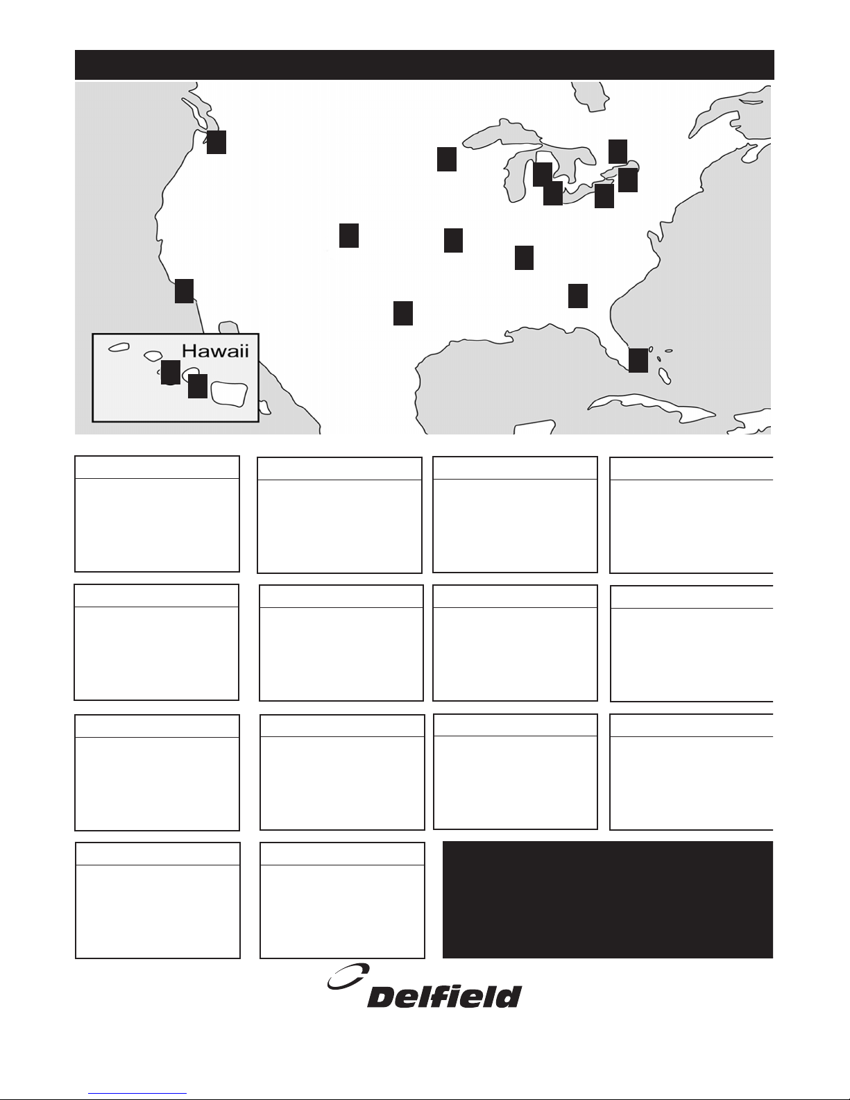
Delfield has 14 conveniently located Parts Depots to
ensure parts are handled promptly and accurately.
Delfield reserves the right to update or make changes
to this list without prior notice
Please call 1-800-733-8829 or check the web at www.delfield.com
for a list of the current Parts Depots.
AUTHORIZED PARTS DEPOTS
MMMILKICE 06/03
 Loading...