

Page 1

Blended Ice Machine
Multiplex Models MS-8
Service Manual
Manufactured exclusively for
McDonald’s® By:
Manitowoc Foodservice
Tel. (888) 436-5442
Tel. (989) 773-7981
Fax (888) 779-2040
MS-8-1H, MS-8-1LH
MS-8-EH, MS-8-ELH
MS-8-AH, MS-8-ALH
MS-8-BH, MS-8-BLH
MS-8-CH, MS-8-CLH
MS-8-FH, MS-8-FLH
MS000A01, MS000A02
MS000A03, MS000A04
MS000A05, MS000A06
Blended Ice Machine
Multiplex
January 2012
Printed in
The United States of America
Page 2

Important Warning And Safety Information
WARNING READ THIS MANUAL THOROUGHLY BEFORE OPERATING, INSTALLING,
OR PERFORMING MAINTENANCE ON THE EQUIPMENT.
WARNING FAILURE TO FOLLOW INSTRUCTIONS IN THIS MANUAL CAN CAUSE
PROPERTY DAMAGE, INJURY OR DEATH.
WARNING DO NOT STORE OR USE GASOLINE OR OTHER FLAMMABLE VAPORS OR
LIQUIDS IN THE VICINITY OF THIS OR ANY OTHER APPLIANCE.
WARNING UNLESS ALL COVER AND ACCESS PANELS ARE IN PLACE AND
PROPERLY SECURED, DO NOT OPERATE THIS EQUIPMENT.
WARNING THIS APPLIANCE IS NOT INTENDED FOR USE BY PERSONS WHO LACK
EXPERIENCE OR KNOWLEDGE, UNLESS THEY HAVE BEEN GIVEN
SUPERVISION OR INSTRUCTION CONCERNING USE OF THE APPLIANCE
BY A PERSON RESPONSIBLE FOR THEIR SAFETY.
WARNING THIS APPLIANCE IS NOT TO BE PLAYED WITH.
WARNING DO NOT CLEAN WITH WATER JET.
WARNING DO NOT USE ELECTRICAL APPLIANCES INSIDE THE FOOD STORAGE
COMPARTMENT OF THIS APPLIANCE.
CAUTION Observe the following:
• Minimum clearances must be maintained from all walls and combustible materials.
• Keep the equipment area free and clear of combustible material.
• Adequate clearance for air openings.
• Operate equipment only on the type of electricity indicated on the specification plate.
• Retain this manual for future reference.
We reserve the right to make product improvements at any time.
Specifi cations and design are subject to change without notice.
Page 3

General Information
Model Numbers . . . . . . . . . . . . . . . . . . . . . . . . . . . . . . . . . . . . . . . . . . . . . . . . . . . . . . . . . . . . 5
Serial Number Location . . . . . . . . . . . . . . . . . . . . . . . . . . . . . . . . . . . . . . . . . . . . . . . . . . . . . . 5
Warranty Information . . . . . . . . . . . . . . . . . . . . . . . . . . . . . . . . . . . . . . . . . . . . . . . . . . . . . . . . 5
Component Identifi cation . . . . . . . . . . . . . . . . . . . . . . . . . . . . . . . . . . . . . . . . . . . . . . . . . . . . . 6
Electrical . . . . . . . . . . . . . . . . . . . . . . . . . . . . . . . . . . . . . . . . . . . . . . . . . . . . . . . . . . . . . . . . . 7
Clearance Requirements . . . . . . . . . . . . . . . . . . . . . . . . . . . . . . . . . . . . . . . . . . . . . . . . . . . . . 8
Heat of Rejection . . . . . . . . . . . . . . . . . . . . . . . . . . . . . . . . . . . . . . . . . . . . . . . . . . . . . . . . . . . 8
General Specifi cations . . . . . . . . . . . . . . . . . . . . . . . . . . . . . . . . . . . . . . . . . . . . . . . . . . . . . . . 8
Location . . . . . . . . . . . . . . . . . . . . . . . . . . . . . . . . . . . . . . . . . . . . . . . . . . . . . . . . . . . . . . . . . . 8
General Maintenance Instructions . . . . . . . . . . . . . . . . . . . . . . . . . . . . . . . . . . . . . . . . . . . . . . 9
Daily Preventive Maintenance Card . . . . . . . . . . . . . . . . . . . . . . . . . . . . . . . . . . . . . . . . . . . . 10
Weekly Preventive Maintenance Card . . . . . . . . . . . . . . . . . . . . . . . . . . . . . . . . . . . . . . . . . . 12
Operation
How to Make a Drink . . . . . . . . . . . . . . . . . . . . . . . . . . . . . . . . . . . . . . . . . . . . . . . . . . . . . . . . 17
How to Replace a Product Bag . . . . . . . . . . . . . . . . . . . . . . . . . . . . . . . . . . . . . . . . . . . . . . . . 18
Shaver Blade Replacement . . . . . . . . . . . . . . . . . . . . . . . . . . . . . . . . . . . . . . . . . . . . . . . . . . . 19
Energize Sequence Flowchart . . . . . . . . . . . . . . . . . . . . . . . . . . . . . . . . . . . . . . . . . . . . . . . . . 20
Make a Drink Energized Component Flowchart . . . . . . . . . . . . . . . . . . . . . . . . . . . . . . . . . . . 21
Rinsing Energized Flowchart . . . . . . . . . . . . . . . . . . . . . . . . . . . . . . . . . . . . . . . . . . . . . . . . . . 24
Manager’s Menu Screen . . . . . . . . . . . . . . . . . . . . . . . . . . . . . . . . . . . . . . . . . . . . . . . . . . . . . 26
Centering the Scale . . . . . . . . . . . . . . . . . . . . . . . . . . . . . . . . . . . . . . . . . . . . . . . . . . . . . . . . . 26
Table of Contents
Troubleshooting
Display Assembly . . . . . . . . . . . . . . . . . . . . . . . . . . . . . . . . . . . . . . . . . . . . . . . . . . . . . . . . . . 27
Blender And Scale . . . . . . . . . . . . . . . . . . . . . . . . . . . . . . . . . . . . . . . . . . . . . . . . . . . . . . . . . . 28
Cooling . . . . . . . . . . . . . . . . . . . . . . . . . . . . . . . . . . . . . . . . . . . . . . . . . . . . . . . . . . . . . . . . . . 29
Cabinet/Product Thermistors . . . . . . . . . . . . . . . . . . . . . . . . . . . . . . . . . . . . . . . . . . . . . . . . . . 29
Ice Shaver/Ice Bin Cover . . . . . . . . . . . . . . . . . . . . . . . . . . . . . . . . . . . . . . . . . . . . . . . . . . . . . 30
Product Dispensing . . . . . . . . . . . . . . . . . . . . . . . . . . . . . . . . . . . . . . . . . . . . . . . . . . . . . . . . . 31
Rinsing And Water Dispensing . . . . . . . . . . . . . . . . . . . . . . . . . . . . . . . . . . . . . . . . . . . . . . . . 32
Refrigeration Operation . . . . . . . . . . . . . . . . . . . . . . . . . . . . . . . . . . . . . . . . . . . . . . . . . . . . . . 33
Will Not Run Flowchart . . . . . . . . . . . . . . . . . . . . . . . . . . . . . . . . . . . . . . . . . . . . . . . . . . . . . . 34
Weight Beam Diagnostic Flowchart . . . . . . . . . . . . . . . . . . . . . . . . . . . . . . . . . . . . . . . . . . . . . 36
Ice Shaver Will Not Run Flowchart . . . . . . . . . . . . . . . . . . . . . . . . . . . . . . . . . . . . . . . . . . . . . 37
Component Check Procedures
ON/OFF Rocker Switch . . . . . . . . . . . . . . . . . . . . . . . . . . . . . . . . . . . . . . . . . . . . . . . . . . . . . . 38
Transformer . . . . . . . . . . . . . . . . . . . . . . . . . . . . . . . . . . . . . . . . . . . . . . . . . . . . . . . . . . . . . . . 38
Control Board Fuse . . . . . . . . . . . . . . . . . . . . . . . . . . . . . . . . . . . . . . . . . . . . . . . . . . . . . . . . . 39
IO (Input/Output) Board . . . . . . . . . . . . . . . . . . . . . . . . . . . . . . . . . . . . . . . . . . . . . . . . . . . . . . 39
LCD Touchscreen & Microprocessor Control Board . . . . . . . . . . . . . . . . . . . . . . . . . . . . . . . . 40
Cabinet Temperature Thermistor . . . . . . . . . . . . . . . . . . . . . . . . . . . . . . . . . . . . . . . . . . . . . . . 40
Product Chase Temperature Thermistor . . . . . . . . . . . . . . . . . . . . . . . . . . . . . . . . . . . . . . . . . 41
Chase Fan . . . . . . . . . . . . . . . . . . . . . . . . . . . . . . . . . . . . . . . . . . . . . . . . . . . . . . . . . . . . . . . . 41
1/12 3
Page 4

Table of Contents (continued)
Component Check Procedures, continued
Evaporator Fan . . . . . . . . . . . . . . . . . . . . . . . . . . . . . . . . . . . . . . . . . . . . . . . . . . . . . . . . . . . . 42
Condenser Fan . . . . . . . . . . . . . . . . . . . . . . . . . . . . . . . . . . . . . . . . . . . . . . . . . . . . . . . . . . . . 42
Ice Bin Lid Microswitch . . . . . . . . . . . . . . . . . . . . . . . . . . . . . . . . . . . . . . . . . . . . . . . . . . . . . . 42
Product Pump . . . . . . . . . . . . . . . . . . . . . . . . . . . . . . . . . . . . . . . . . . . . . . . . . . . . . . . . . . . . . 43
Solenoid Valves . . . . . . . . . . . . . . . . . . . . . . . . . . . . . . . . . . . . . . . . . . . . . . . . . . . . . . . . . . . . 43
Shaver Motor . . . . . . . . . . . . . . . . . . . . . . . . . . . . . . . . . . . . . . . . . . . . . . . . . . . . . . . . . . . . . . 43
Circuit Breaker . . . . . . . . . . . . . . . . . . . . . . . . . . . . . . . . . . . . . . . . . . . . . . . . . . . . . . . . . . . . . 44
Blender Motor . . . . . . . . . . . . . . . . . . . . . . . . . . . . . . . . . . . . . . . . . . . . . . . . . . . . . . . . . . . . . 44
Manual Rinse Push Button . . . . . . . . . . . . . . . . . . . . . . . . . . . . . . . . . . . . . . . . . . . . . . . . . . . 44
Compressor Electrical Diagnostics . . . . . . . . . . . . . . . . . . . . . . . . . . . . . . . . . . . . . . . . . . . . . 45
Discharge Pressure High Checklist . . . . . . . . . . . . . . . . . . . . . . . . . . . . . . . . . . . . . . . . . . . . . 46
Discharge Pressure Low Checklist . . . . . . . . . . . . . . . . . . . . . . . . . . . . . . . . . . . . . . . . . . . . . 46
Suction Pressure High Checklist . . . . . . . . . . . . . . . . . . . . . . . . . . . . . . . . . . . . . . . . . . . . . . . 46
Suction Pressure Low Checklist . . . . . . . . . . . . . . . . . . . . . . . . . . . . . . . . . . . . . . . . . . . . . . . 46
Recovery/Evacuation . . . . . . . . . . . . . . . . . . . . . . . . . . . . . . . . . . . . . . . . . . . . . . . . . . . . . . . . 47
Assembly & Replacement Parts List
Base . . . . . . . . . . . . . . . . . . . . . . . . . . . . . . . . . . . . . . . . . . . . . . . . . . . . . . . . . . . . . . . . . . . . 48
Top . . . . . . . . . . . . . . . . . . . . . . . . . . . . . . . . . . . . . . . . . . . . . . . . . . . . . . . . . . . . . . . . . . . . . . 49
Duct Outlet . . . . . . . . . . . . . . . . . . . . . . . . . . . . . . . . . . . . . . . . . . . . . . . . . . . . . . . . . . . . . . . . 50
Door . . . . . . . . . . . . . . . . . . . . . . . . . . . . . . . . . . . . . . . . . . . . . . . . . . . . . . . . . . . . . . . . . . . . . 50
Miscellaneous . . . . . . . . . . . . . . . . . . . . . . . . . . . . . . . . . . . . . . . . . . . . . . . . . . . . . . . . . . . . . 50
Top Valve & Pump . . . . . . . . . . . . . . . . . . . . . . . . . . . . . . . . . . . . . . . . . . . . . . . . . . . . . . . . . . 51
Lower Pump . . . . . . . . . . . . . . . . . . . . . . . . . . . . . . . . . . . . . . . . . . . . . . . . . . . . . . . . . . . . . . 51
VitaMix Assembly . . . . . . . . . . . . . . . . . . . . . . . . . . . . . . . . . . . . . . . . . . . . . . . . . . . . . . . . . . 52
Condensing Unit . . . . . . . . . . . . . . . . . . . . . . . . . . . . . . . . . . . . . . . . . . . . . . . . . . . . . . . . . . . 53
Evaporator Coil . . . . . . . . . . . . . . . . . . . . . . . . . . . . . . . . . . . . . . . . . . . . . . . . . . . . . . . . . . . . 53
Refrigerant Recovery/Evacuation & Charging Procedures
Charging Procedures . . . . . . . . . . . . . . . . . . . . . . . . . . . . . . . . . . . . . . . . . . . . . . . . . . . . . . . . 54
System Contamination Cleanup . . . . . . . . . . . . . . . . . . . . . . . . . . . . . . . . . . . . . . . . . . . . . . . 54
Mild System Contamination Cleanup Procedure . . . . . . . . . . . . . . . . . . . . . . . . . . . . . . . . . . . 55
Severe System Contamination Cleanup Procedure . . . . . . . . . . . . . . . . . . . . . . . . . . . . . . . . 55
R-290 Service Procedure . . . . . . . . . . . . . . . . . . . . . . . . . . . . . . . . . . . . . . . . . . . . . . . . . . . . 56
Filter-Driers . . . . . . . . . . . . . . . . . . . . . . . . . . . . . . . . . . . . . . . . . . . . . . . . . . . . . . . . . . . . . . . 56
Total System Refrigerant Charge . . . . . . . . . . . . . . . . . . . . . . . . . . . . . . . . . . . . . . . . . . . . . . 56
Operating Pressures Chart . . . . . . . . . . . . . . . . . . . . . . . . . . . . . . . . . . . . . . . . . . . . . . . . . . . 56
Specifi cations/Wiring Diagrams/Schematics
Wiring Diagrams . . . . . . . . . . . . . . . . . . . . . . . . . . . . . . . . . . . . . . . . . . . . . . . . . . . . . . . . . . . 57
Blender Scale & Shaver Schematics . . . . . . . . . . . . . . . . . . . . . . . . . . . . . . . . . . . . . . . . . . . . 58
Electronic Control Board . . . . . . . . . . . . . . . . . . . . . . . . . . . . . . . . . . . . . . . . . . . . . . . . . . . . . 60
BIM Warranty Guidelines . . . . . . . . . . . . . . . . . . . . . . . . . . . . . . . . . . . . . . . . . . . . . . . . . . . . . . . . . . . . . . . . 61
Notes. . . . . . . . . . . . . . . . . . . . . . . . . . . . . . . . . . . . . . . . . . . . . . . . . . . . . . . . . . . . . . . . . . . . . . . . . . . . . . . . . 62
4 1/12
Page 5

General Information
Model Numbers
This manual covers the Blended Ice Machine, model
numbers MS-8-1H, MS-8-1LH, MS-8-EH, MS-8-ELH,
MS-8-AH, MS-8-ALH, MS-8-BH, MS-8-BLH, MS-8CH, MS-8-CLH, MS-8-FH, MS-8-FLH, MS000A01,
MS000A02, MS000A03, MS000A04, MS000A05 and
MS000A06.
Serial Number Location
This number is required when requesting information
from your local distributor. The serial number is listed
on the SERIAL NUMBER DECAL affi xed to the middle
of the lower back panel on the Blended Ice Machine. A
second decal is located on the front right side of cup
dispenser.
General Warranty Information
Your Blended Ice Machine comes with a three-year
warranty on parts and labor and a fi ve-year warranty on
compressor. Consult your local Multiplex Distributor for
terms and conditions of your warranty. Your warranty
specifi cally excludes all general adjustments, cleaning,
accessories and related servicing.
The warranty card must be returned to activate the
warranty on this equipment. If a warranty card is not
returned, the warranty period can begin when the
equipment leaves the Multiplex factory.
No equipment may be returned to without a written
Return Materials Authorization (RMA). Equipment
returned without an RMA will be refused at dock and
returned to the sender at the sender’s expense.
Please contact your local distributor for return
procedures.
The following Warranty outline is provided for your
convenience. For a detailed explanation, read the
warranty bond shipped with each product.
Contact your local Multiplex representative or Multiplex
if you need further warranty information.
PARTS
Multiplex warrants Blended Ice Machine parts against
defects in materials and workmanship, under normal
use and service for three (3) years from the date of
original installation.
The compressor is covered by an additional two (2) year
part only warranty beginning on the date of the original
installation.
LABOR
Labor required to repair or replace defective
components is covered for three (3) years from the date
of original installation.
EXCLUSIONS
The following items are not included in the Blended Ice
Machine warranty coverage:
Normal maintenance, adjustments and cleaning as
outlined in this manual.
Repairs due to unauthorized modifi cations to the
Blended Ice Machine or use of non-standard parts
without prior written approval from Multiplex.
Damage caused by improper installation of the Blended
Ice Machine, electrical supply, water supply or drainage,
or damage caused by fl oods, storms, or other acts of
God.
Premium labor rates due to holidays, overtime, etc.;
travel time; fl at rate service call charges; mileage and
miscellaneous tools and material charges not listed
on the payment schedule. Additional labor charges
resulting from the inaccessibility of equipment are also
excluded.
Parts or assemblies subjected to misuse, abuse,
neglect or accidents.
Damage or problems caused by installation, cleaning
and/or maintenance procedures inconsistent with the
technical instructions provided in this manual.
AUTHORIZED WARRANTY SERVICE
To comply with the provisions of the warranty, a
refrigeration service company qualifi ed and authorized
by your Multiplex Distributor, or a Contracted Service
Representative must perform the warranty repair.
SERVICE CALLS
Normal maintenance, adjustments and cleaning
as outlined in this manual are not covered by the
warranty. If you have followed the procedures listed in
this manual, and the Blended Ice Machine still does
not perform properly, call your Local Distributor or the
Multiplex Service Department.
1/12 5
Page 6
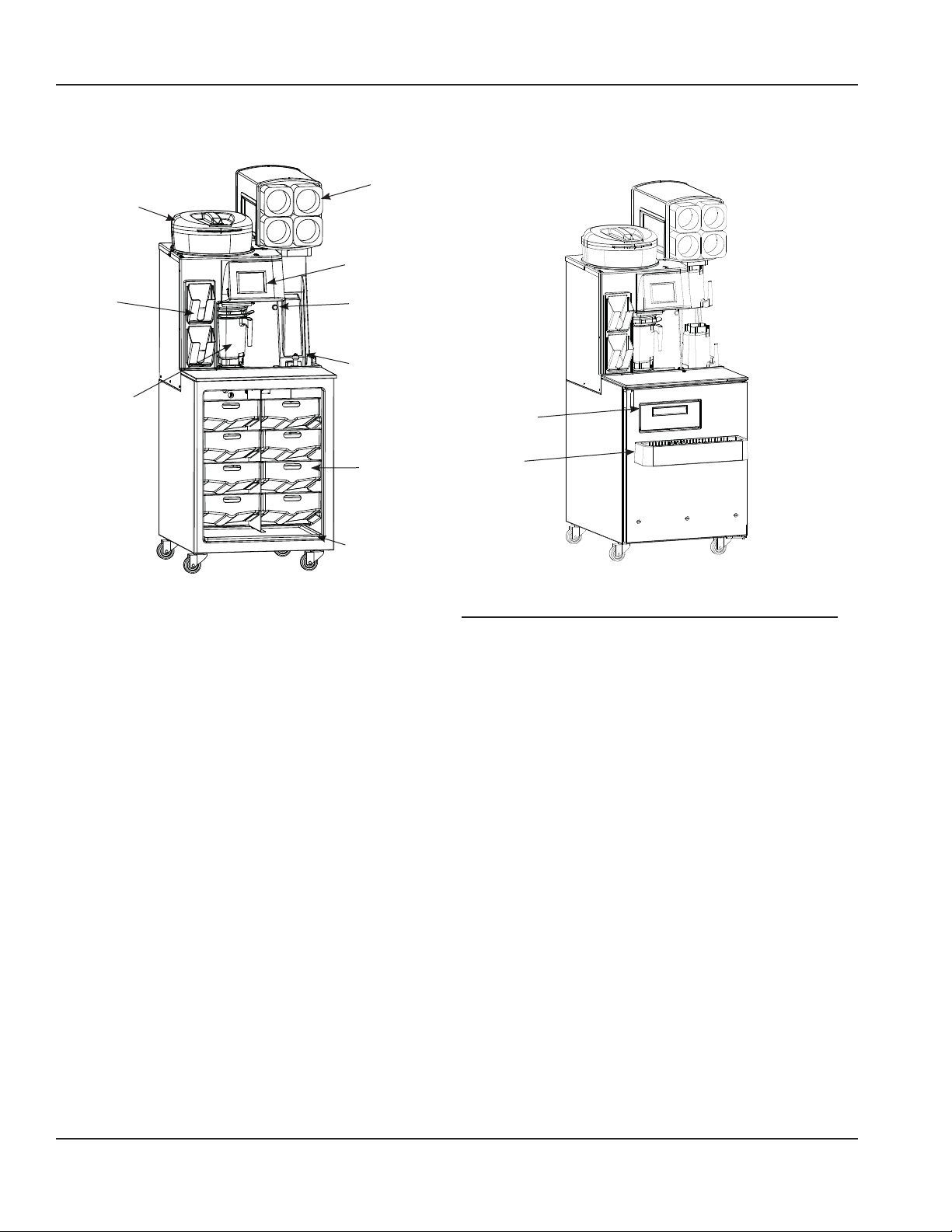
Component Identifi cation
Cup
Dispenser
Ice Hopper Lid
(VMP00133)
(1706175)
Touch
Screen
Lid
Dispenser
(1706142)
Blender Fill
Pitcher
Manual Rinse
Button
Blender Rinse
Location
Product
Bins
(1706268)
Pull Out Tray
(076-CDZ-0000)
General System Overview
The Blended Ice Machine is a self-contained dispensing
unit that allows the operator to make fl avor combinations
of blended ice drinks. It contains product fl avoring in a
reach-in enclosure, a refrigeration system and an ice
shaving machine.
The operator controls and accesses the unit using
a lighted touch screen. Icons on the Drink Selection
screen represent the primary fl avor combinations for
the blended ice drinks. A second screen provides drink
size options (S, M, L) and ingredient options, such as
“no yogurt.” Menu changes and additions are uploaded
using a USB mass storage device.
On-screen instructions also include operator procedures
for cleaning/sanitizing, checking inventory, replacing
product bags, selecting drink sizes and manually
preparing drinks. Managers and technicians have
access to menu/software updates, diagnostics and
other service screens.
Whipped
Cream Door
(000-187-0016)
Syrup Rail
(1706194)
Syrup Rail Divider
(1706195)
Part Description Number
Cleaning Kit 000-BIC-0008
Cleaning Pitcher 3239631
Cup Dispenser 1706175
Gasket, Door 1706208
Gasket, Whipped Cream Door 1706209
Hinge Kit RF000066
Ice Hopper Lid VMP00133
Lid Dispenser 1706142
Product Bin 1706268
Pull Out Tray 076-CDZ-0000
Syrup Rail 1706194
Syrup Rail Divider 1706195
Whipped Cream Door 000-187-0016
6 1/12
Page 7

Electrical
GENERAL
!
Warning
All wiring must conform to local, state and national
codes.
MINIMUM CIRCUIT AMPACITY
The minimum circuit ampacity is used to help select
the wire size of the electrical supply. (Minimum circuit
ampacity is not the Blended Ice Machine’s running amp
load.) The wire size (or gauge) is also dependent upon
location, materials used, length of run, etc., so it must
be determined by a qualifi ed electrician.
ELECTRICAL REQUIREMENTS
Refer to Blended Ice Machine Model/Serial Plate for
voltage/amperage specifi cations. A dedicated electrical
circuit is required.
MINIMUM CIRCUIT AMPERAGE CHART
Important
Due to continuous improvements, this information is
for reference only. Please refer to the serial number
tag to verify electrical data. Serial tag information
overrides information listed on this page.
Model
Numbers
MS-8-1H,
MS-8-1LH,
MS-8-FH,
MS-8-FLH,
MS000A05,
MS000A06
MS-8-BH
MS-8-BLH
MS-8-AH,
MS-8-ALH,
MS-8-CH,
MS-8-CLH,
MS-8-EH,
MS-8-ELH,
MS000A01,
MS000A02,
MS000A03,
MS000A04
Voltage/Cycle
115/60/1 16.0 20A
230-240/60/1 9.8 16A
230-240/50/1 9.8 16A
Total
Amps
Breaker
Size
GROUNDING INSTRUCTIONS
!
Warning
The machine must be grounded in accordance with
national and local electrical codes.
This appliance must be grounded. In the event of
malfunction or breakdown, grounding provides a path
of least resistance for electric current to reduce the
risk of electric shock. This appliance is equipped with
a cord having an equipment-grounding conductor
and a grounding plug. The plug must be plugged
into an appropriate outlet that is properly installed
and grounded in accordance with all local codes and
ordinances.
EXPORT NOTE: For export models replace the supply
2
cord with a 1.5mm
minimum, 3 conductor H05VV-F
harmonized cord.
1/12 7
Page 8

Clearance Requirements
Model Air Cooled
Top 8" (20 cm)
Sides 6" (15 cm)
Back 6" (15 cm)
Front 30" (76 cm)
Heat of Rejection
Heat of Rejection
Air Conditioning
BTUh/kW
2100/0.62 2600/0.76
Peak
General Specifi cations
Temperature Control Setting 36°F setpoint 4°F differential
2°C setpoint 2°C differential
controlled by software
Ice Capacity 23 lbs (10 kg)
Shipping Weight 430 lbs (195 kg)
Product Bin Capacity 19.8lbs (9kg) per bin
CO
Regulator Setting 40psi (276 kPa)
2
Water Regulator Setting 30psi (207 kPa)
Location
The location selected for the Blended Ice Machine must
meet the following criteria.
• The air temperature must be at least 40°F (4°C), but
must not exceed 90°F (32°C), climate class 4.
• The location must not be near heat-generating
equipment or in direct sunlight and must be
protected from weather.
• Water temperature min/max = 40°F/110°F
(4°C/43°C).
• Water pressure min/max = 20 psi/40 psi
(138kPa/276kPa)
• Always use the water supply line supplied when
installing this appliance. Never reuse an old supply
line.
• Main supply CO
Machine regulator min/max = 55 psi/150 psi
(379kPa/1034kPa)
Carbon Dioxide (CO2) displaces oxygen. Exposure
to a high concentration of CO2 gas causes tremors,
which are followed rapidly by loss of consciousness
and suffocation. If a CO2 gas leak is suspected,
particularly in a small area, immediately ventilate
the area before repairing the leak. CO2 lines and
pumps must not be installed in an enclosed space.
An enclosed space can be a cooler or small room
or closet. This may include convenience stores with
glass door self serve coolers. If you suspect CO2
may build up in an area, venting of the B-I-B pumps
and / or CO2 monitors must be utilized.
pressure to Blended Ice
2
!
Warning
8 1/12
Page 9

Maintenance
Door Gasket Maintenance
Door gaskets require regular cleaning to prevent mold and
mildew build up and also to retain the elasticity of the gasket.
Gasket cleaning can be done with the use of warm soapy water.
Avoid full strength cleaning products on gaskets as this can
cause them to become brittle and crack. Never use sharp tools
or knives to scrape or clean the gasket. Gaskets can be easily
replaced and do not require the use of tools or an authorized
service person. The gaskets are “Dart” style and can be pulled
out of the groove in the door and new gaskets can be “pressed”
back into place.
Drain Maintenance - Base
Each unit has a drain located inside the unit that removes
the condensation from the evaporator coil and routes it to an
external condensate evaporator pan. Each drain can become
loose or disconnected during normal use. If you notice water
accumulation on the inside of the unit be sure the drain tube
is connected to the evaporator drain pan. If water is collecting
underneath the unit make sure the end of the drain tube is in
the condensate evaporator in the machine compartment. The
leveling of the unit is important as the units are designed to
drain properly when level. Be sure all drain lines are free of
obstructions.
Caster Maintenance
Wipe casters with a damp cloth monthly to prevent corrosion.
The power switch must be turned to OFF and the
unit disconnected from the power source whenever
performing service, maintenance functions or
cleaning the refrigerated area.
Refrigerators
The interior and exterior can be cleaned using soap and
warm water. If this isn’t suffi cient, try ammonia and water or a
nonabrasive liquid cleaner. When cleaning the exterior, always
rub with the “grain” of the stainless steel to avoid marring the
fi nish. Do not use an abrasive cleaner because it will scratch the
stainless steel and can damage the breaker strips and gaskets.
Stainless Steel Care and Cleaning
To prevent discoloration or rust on stainless steel several
important steps need to be taken. First, we need to understand
the properties of stainless steel. Stainless steel contains 70- 80%
iron, which will rust. It also contains 12-30% chromium, which
forms an invisible passive fi lm over the steel’s surface, which
acts as a shield against corrosion. As long as the protective
layer is intact, the metal is still stainless. If the fi lm is broken
or contaminated, outside elements can begin to breakdown the
steel and begin to form discoloration or rust. Proper cleaning of
stainless steel requires soft cloths or plastic scouring pads.
NEVER USE STEEL P ADS, WIRE BRUSHES OR SCRAPERS!
Cleaning solutions need to be alkaline based or non-chloride
cleaners. Any cleaner containing chlorides will damage
the protective fi lm of the stainless steel. Chlorides are also
commonly found in hard water, salts, and household and
industrial cleaners. If cleaners containing chlorides are used be
sure to rinse repeatedly and dry thoroughly. Routine cleaning
of stainless steel can be done with soap and water. Extreme
stains or grease should be cleaned with a non-abrasive cleaner
and plastic scrub pad. Always rub with the grain of the steel.
There are stainless steel cleaners available which can restore
and preserve the fi nish of the steels protective layer. Early signs
of stainless steel breakdown are small pits and cracks. If this
has begun, clean thoroughly and start to apply stainless steel
cleaners in attempt to restore the passivity of the steel.
Never use an acid based cleaning solution! Many
food products have an acidic content, which can
deteriorate the fi nish. Be sure to clean the stainless
steel surfaces of ALL food products. Common items
include, tomatoes, peppers and other vegetables.
Cleaning the Condenser Coil
In order to maintain proper refrigeration performance, the
condenser fi ns must be cleaned of dust, dirt and grease
regularly. It is recommended that this be done at least every
three months. If conditions are such that the condenser is totally
blocked in three months, the frequency of cleaning should be
increased. Clean the condenser with a vacuum cleaner or stiff
brush. If extremely dirty, a commercially available condenser
cleaner may be required.
Failure to maintain a clean condenser coil can initially cause high
temperatures and excessive run times. Continuous operation
with a dirty or clogged condenser coil can result in compressor
failure. Neglecting the condenser coil cleaning procedures will
void any warranties associated with the compressor and cost to
replace the compressor.
Never use a high-pressure water wash for this
cleaning procedure as water can damage the
electrical components located near or at the
condenser coil.
Doors/Hinges
Over time and with heavy use doors the hinges may become
loose. If this happens tighten the screws that mount the hinge
brackets to the frame of the unit. Loose or sagging doors can
cause the hinges to pull out of the frame, which may damage
both the doors and the hinges. In some cases this may require
qualifi ed service agents or maintenance personnel to perform
repairs.
Do not place hot pans on/against the blue ABS
liner. Do not throw items into the storage area.
Failure to follow these recommendations could
result in damage to the interior of the cabinet or
to the blower coil. Overloading the storage area,
restricting the airfl ow, and continuous opening and
closing of the doors and drawers will hamper the
units ability to maintain operational temperature.
Preventing blower coil corrosion
To help prevent corrosion of the blower coil, store all acidic
items, such as pickles and tomatoes, in sealable containers.
Immediately wipe up all spills.
Continuous opening and closing of the doors will hamper the
unit’s ability to maintain optimum refrigeration temperature. Top
section is not intended for overnight storage. Product should be
removed from pans. Pans can remain in unit while empty.
1/12 9
Page 10

Clean Blended Ice Machine (BIM-8)
Why
Time required
Time of day
Hazard icons
To break the bacteria cycle
5 minutes to prepare 15 minutes to complete
At close For 24-hour restaurants: During low-volume periods
Chemicals
Daily BE 23 D1
Blended Ice Machine Models MS-8-1H, MS-8-1LH, MS-8-EH, MS-8-ELH, MS-8-BH, MS-8-BLH, MS-8-CH, MS-8-CLH, MS000A03, MS000A04
Precaution:
Hazard Communication Standard (HCS) –The procedures on this card include the use of chemical products.
These chemical products will be highlighted with bold face letters followed by the abbreviation (HCS) in the
tools portion of the procedure. See the Hazard Communication Standard (HCS) manual for the appropriate
Material Safety Data Sheet(s) (MSDS).
Tools and supplies
Bucket, clean and
sanitized towels
Scoop Bucket, soiled towels KAY 5Sanitizer
Procedure
Cycle touch pad to cleaning.
1
On the Menu Screen press
Cleaning, then Daily
Cleaning.
Gather items shown.
2
solution (HCS)
KAY Beverage
Equipment Cleaner
5
No-Scratch Pad
Remove parts for cleaning and
sanitizing.
Remove the following items
and take them back to the 3
compartment sink to wash,
rinse and sanitize.
x Blender pitchers
x Ice hopper lid
x Syrup rail
x Drip pan
x Splash guard
Do not place parts in “Power
Soaker” or dishwasher.
Empty ice hopper.
3
continued X
Remove ice hopper lid. Use
an ice scoop and an empty
bucket to remove as much ice
as possible from above the ice
shelf. Replace ice hopper lid.
Manually dispense ice.
4
Daily BE 23 D1
Place a blend pitcher on the
pitcher pad. Press Manual Ice
Dispense button until ice
hopper is empty. Remove
blender pitcher of ice and
discard in back sink.
©McDonald’s Corporation · Planned Maintenance Manual · October2011 Page 1of 2
10 1/12
Page 11

Clean Blended Ice Machine (BIM-8)(continued)
With the blender pitchers at
6
the 3-compartment sink, clean
pitchers.
Place one KAY Beverage
Equipment Cleaner packet
into the first pitcher and fill
with hot water from the back
sink. Allow the product to
soak in the pitcher for 5
minutes. Use a no-scratch pad
to remove any film build-up.
Pour the solution into the
second pitcher and soak for 5
minutes. Once this is done,
discard solution, rinse and
sanitize bot h pitchers in t he 3compartment sink. Allow to
air dry.
KAY Beverage Equipment
Cleaner
Sanitize ice chute
7
Use a spray bottle with
Sanitizer solution and a
sanitized towel to sanitize:
x Above and around the
ice chute
x Inside the ice chute
KAY 5 Sanitizer
Re-install all components.
9
Blend pitchers, ice hopper lid,
syrup rails, drip pan and
splash guard.
Clean with APSC the interior of
10
the blended ice machine with a
clean, sanitized towel
dampened with KAY 5
Sanitizer solution:
x Clean inside the
machine.
x Pull out the whipped
cream holder and clean
the holder and sides
inside the machine that
hold the holder
x Clean all door gaskets
KAY 5 Sanitizer
Clean with APSC the exterior
11
of the blended ice machine
with a clean, sanitized towel
dampened with KAY 5
Sanitizer solution:
x Clean lid holders, cup
holder tubes, cabinet,
front of door, top of
work surface, touch
screen, outside of ice
hopper
Blended Ice Machine Models MS-8-1H, MS-8-1LH, MS-8-EH, MS-8-ELH, MS-8-BH, MS-8-BLH, MS-8-CH, MS-8-CLH, MS000A03, MS000A04
Clean pitcher pad and drain
8
area.
x Use coffee pot of hot
water from the back
sink to rinse drain
area and drain.
x Spray the drain area
with Sanitizer
solution and wipe
with a clean sanitize
towel.
x Clean top and sides
of the pad.
KAY 5 Sanitizer
KAY 5 Sanitizer
Daily BE 23 D1
©McDonald’s Corporation · Planned Maintenance Manual · October2011 Page 2of 2
1/12 11
Page 12

Clean Blended Ice Machine (BIM-8)
Why
Time required
Time of day
Hazard icons
To break the bacteria cycle
10 minutes to prepare 50 minutes to complete
At close For 24-hour restaurants: During low-volume periods
Electricity
Chemicals
Weekly BE 23 W1
Blended Ice Machine Models MS-8-1H, MS-8-1LH, MS-8-EH, MS-8-ELH, MS-8-BH, MS-8-BLH, MS-8-CH, MS-8-CLH, MS000A03, MS000A04
Sharp Objects/Surfaces
Precaution:
Hazard Communication Standard (HCS) –The procedures on this card include the use of chemical products.
These chemical products will be highlighted with bold face letters followed by the abbreviation (HCS) in the
tools portion of the procedure. See the Hazard Communication Standard (HCS) manual for the appropriate
Material Safety Data Sheet(s) (MSDS).
Tools and supplies
Cleaning Pitcher Cleaning Tubes Bucket with SolidSense All
Bucket, clean,
sanitizer-soaked towels
Bucket, soiled towels KAY 5SanitizerSolution Scoop Empty bucket KAY Beverage Equipment
Purpose Super Concentrate
(APSC)
Procedure
Cycle touch pad to cleaning.
1
On the Menu screen press
Cleaning, then Weekly
Cleaning.
Bucket with 2 KAY5
Sanitizer (HCS) packet
4
Bucket with rinse water Bio-Shield Dispenser Bio-Shield Tower Drain
Cleaner
Cleaner
Taylor Lube HP or
Carpigiani Carpilub e
Manually dispense ice.
Place a blend pitcher on the
pitcher pad. Press Manual Ice
Dispense button until ice
hopper is empty. Remove
blender pitcher of ice and
discard in back sink.
Fill each labeled bucket to the
5
fill line with the appropriate
solution and bring to machine.
Fill APSC bucket with hot
SolidSense APSC from
Gather items shown.
2
Empty ice hopper.
3
Remove ice hopper lid. Use
an ice scoop and an empty
bucket to remove as much ice
as possible from above the ice
shelf. Replace ice hopper lid.
dispenser at 3-compartment
sink.
Fill RINSE bucket with
warm, clean water.
Fill SANITIZE bucket with 5
gallons of lukewarm water
and 2 packets of
KAY 5
Sanitizer and mix thoroughly.
continued X
©McDonald’s Corporation · Planned Maintenance Manual · October2011 Page 1of 5
Weekly BE 23 W1
12 1/12
Page 13

Clean Blended Ice Machine (BIM-8)(continued)
Remove product bins and
6
bags.
Remove each product bag
from the product bin and
place in walk-in cooler. Take
product bins to 3compartment sink and wash,
rinse and sanitize. Allow to
air dry.
Connect cleaning tubes.
7
Connect one tube from the
cleaning tubes to each inlet
line. Insert the free end of the
tubes into the bucket of clean
SolidSense APSC solution.
All lines must be cleaned
including unused.
Chemicals
SolidSense APSC solution
Place black cleaning pitcher
8
on pitcher pad.
Press Next.
9
The message window will
display: “APSC cleaning of
Strawberry Banana
then change to the next flavor
until all lines have been
cleaned. If cleaner solution
runs low, press Pause, refill
the bucket with cleaner
solution and press Resume.
After the last line is cleaned,
the next cleaning screen will
appear.
Line”,
Press Next.
11
The message window will
display: “Rinse of
Banana Line”, then change to
the next flavor until all lines
have been rinse d. If water
runs low, press Pause, refill
the bucke t with warm wa t er
and press Resume. After the
last line is cleaned, the next
cleaning screen will appear.
Remove tubes from RINSE
12
bucket and place into the
warm water SANITIZE bucket.
Chemicals
KAY 5 Sanitizer
Press Next.
13
The message window will
display: “Sanitizer fill of
Strawberry Banana
then change to the next flavor
until all lines have been
sanitized. If sanitizer solution
runs low, press Pause, refill
the bucket with sanitizer
solution and press Resume.
Sanitize Hold
14
After the last line is sanitized,
“Sanitize Hold” will appear,
and then the next cleaning
screen will appear.
Remove tubes from Sanitize
15
solution and lay across the top
rim of the bucket.
BleBlended Ice Machine Models MS-8-1H, MS-8-1LH, MS-8-EH, MS-8-ELH, MS-8-BH, MS-8-BLH, MS-8-CH, MS-8-CLH,MS000A03, MS000A04
Strawberry
Line”,
Remove tubes from the APSC
10
bucket and place into the
warm water RINSE bucket.
Press Next.
16
The message window will
display: “Auto purge of
Strawberry Banana
then change to the next flavor
until all lines have been
purged. The next cleaning
screen will appear.
Disconnect the cleaning tubes
17
from each product line.
©McDonald’s Corporation · Planned Maintenance Manual · October2011 Page 2of 5
Line”,
continued X
Weekly BE 23 W1
1/12 13
Page 14

Clean Blended Ice Machine (BIM-8)(continued)
Lube each product line.
18
Use either Taylor Lube HP or
Carpigiani Carpilube. Put a
small amount of lube around
each product line.
Pull the bottom drain pan from
19
inside the machine.
Reconnect product bins and
20
bags.
Retrieve product bags from
walk-in cooler. Install product
bags into the product bins.
Position the rear groove of the
spout on the product bag into
the front slot of the product
bin. Make sure it’s properly
snapped into place. Then
install each product bin into
its proper location.
Replace black cleaning pitcher
21
with blending pitcher.
Place discharged product in
trash or back sink.
Remove Ice hopper lid.
22
Use clean sanitizer-soaked
26
towel to clean inside of
hopper.
Use caution when wip i ng ne ar
the shaver blade.
Sharp Objects/Surfaces
Rinse ice hopper with clean
27
water.
Fill a blend pitcher with clean
water. Slowly pour the clean
water into the ice hopper in a
circular motion, as close to
and as high up the inside
walls as possible, without
splashing outside the unit.
Repeat if needed for a
thorough rinse.
Remove black cleaning pitcher
28
from the pitcher pad, be
careful not to splash any
remaining solution from the
pitcher.
Spray interior of ice hopper
29
with Sanitizer Solution.
Allow to air dry.
Sharp Objects/Surfaces
Use caution when ne ar the
shaver blade.
KAY 5 Sanitizer
BleBlended Ice Machine Models MS-8-1H, MS-8-1LH, MS-8-EH, MS-8-ELH, MS-8-BH, MS-8-BLH, MS-8-CH, MS-8-CLH,MS000A03, MS000A04
Remove parts for cleaning and
30
sanitizing.
Place black cleaning pitcher
23
on the pitcher pad.
Fill a blend pitcher with
24
SolidSense APSC.
Chemicals
SolidSense APSC
Pour in SolidSense APSC.
25
Slowly pour the SolidSense
APSC into the ice hopper in a
circular motion, as close to
and as high up the inside
walls as possible, without
splashing solution outside the
unit.
Remove the following items
and take them back to the 3compartment sink to wash,
rinse and sanitize:
x Blend pitchers
x Scale overflow tray
x Ice hopper lid
x Syrup rail
x Drip pan
x Splash guard
Do not place parts in “Power
Soaker” or dishwasher.
continued X
©McDonald’s Corporation · Planned Maintenance Manual · October2011 Page 3of 5
Weekly BE 23 W1
14 1/12
Page 15

Clean Blended Ice Machine (BIM-8)(continued)
With the blender pitchers at
31
the 3-compartment sink:
Place one KAY Beverage
Equipment Cleaner packet
into the first pitcher and fill
with hot water from the back
sink. Allow the product to
soak in the pitcher for 5
minutes. Use a no-scratch pad
to remove any film build-up.
Pour the solution into the
second pitcher and soak for 5
minutes. Once this is done,
discard solution and rinse and
sanitize bot h pitchers in t he 3compartment sink. Allow to
air dry.
KAY Beverage Equipment
Cleaner
Sanitize ice chute
32
Use a spray bottle with
Sanitizer solution and a
sanitized towel to sanitize:
x Above and around the
ice chute
x Inside the ice chute
Clean with APSC the interior of
35
the blended ice machine with a
clean, sanitized towel
dampened with KAY 5
Sanitizer solution:
x Clean inside the
machine.
x Pull out the whipped
cream holder and clean
the holder and sides
inside the machine that
hold the holder
x Clean all door gaskets
KAY 5 Sanitizer
Clean with APSC the exterior
36
of the blended ice machine
with a clean, sanitized towel
dampened with KAY 5
Sanitizer solution:
x Clean lid holders, cup
holder tubes, cabinet,
front of door, top of
work surface, touch
screen, outside of ice
hopper
BleBlended Ice Machine Models MS-8-1H, MS-8-1LH, MS-8-EH, MS-8-ELH, MS-8-BH, MS-8-BLH, MS-8-CH, MS-8-CLH,MS000A03, MS000A04
KAY 5 Sanitizer
Clean pitcher pad and drain
33
area.
x Use coffee pot of hot
water from the back
sink to rinse drain
area and drain.
x Spray the drain area
with Sanitizer
solution and wipe
with a clean sanitize
towel.
x Clean top and sides
of the pad.
KAY 5 Sanitizer
Re-install all components.
34
Blend pitchers, scale overflow
tray, ice hopper lid, syrup
rails, drip pan and splash
guard.
KAY 5 Sanitizer
Slowly pour two full pitchers of
37
hot water from the back sink
into the rinse area.
On top of the BIO-SHIELD®
38
dispenser open the pressure
relief knob by turning the knob
counter clockwise.
Remove the cap from the BIO-
39
SHIELD® dispenser.
Weekly BE 23 W1
continued X
©McDonald’s Corporation · Planned Maintenance Manual · October2011 Page 4of 5
1/12 15
Page 16

Clean Blended Ice Machine (BIM-8)(continued)
4
4
4
4
4
4
4
Pour two full pitchers of hot
0
water from the back sink into
the dispenser.
Quickly pour one packet of
1
BIO-SHIELD Beverage Tower
Drain Cleaner into the
dispenser.
Immediately replace and
tighten the cap. Then on top
of the BIO-SHIELD®
dispenser close the pressure
relief knob by turning the
knob clockwise. Shake the
dispenser to dissolve the
cleaner.
Drain Cleaner.
Carefully purge a small
2
amount of solution from the
dispenser into the back sink or
utility sink.
This helps prevent
“sputtering” of solution and
possible splashing ba ck onto
clothing or eyes.
Rinse the BIO-SHIELD®
6
dispenser.
Rinse the BIO-SHIELD®
dispens er wi th warm wa te r
and return the dispenser to the
proper storage area.
IMPORTANT! Do not use
the drain for at least four
hours after cleaning. But
the machine can still be
used.
BleBlended Ice Machine Models MS-8-1H, MS-8-1LH, MS-8-EH, MS-8-ELH, MS-8-BH, MS-8-BLH, MS-8-CH, MS-8-CLH,MS000A03, MS000A04
Carefully spray the solution
3
into the rinser sink drain hole.
Open the pressure relief knob
4
again by turning the knob
counter clockwise on top of
the BIO-SHIELD® dispenser.
Remove the cap from the BIO-
5
SHIELD® dispenser.
Weekly BE 23 W1
©McDonald’s Corporation · Planned Maintenance Manual · October2011 Page 5of 5
16 1/12
Page 17

Operation
Procedure to Make a Drink
NOTE: Ice must be present in the ice bin and product
must be connected and primed to produce a drink.
Size and Option Touch Screen
3. Select drink options:
Drink Selection Touch Screen
1. Place a clean blend container on the container pad.
2. Press the touch screen to select the type of drink
desired from list of main menu items. The screen
will advance and list the selection. (If the selection
is incorrect, press return and reselect).
- Select Return to view the previous screen.
- The yogurt button toggles between including and
leaving out the yogurt.
- Select the Multiple button if you want to make
multiple drinks of the same fl avor.
- Select drink size(s).
NOTE: A green box will highlight the selections.
4. The machine will add the proper amount of
ingredients, blend and stop automatically.
5. Pour the drink into a properly sized cup for the drink
selection.
6. Place container in rinse position – container is
automatically rinsed.
1/12 17
Page 18

Procedure to Replace a Product Bag
These instructions can be found on the Touch Screen in
the Help Menu under “Replace Product”.
1. Touchscreen will indicate the bag is empty “Drink
making paused, check product supply”.
2. Press “Replace product”.
3. Use the arrows and the Confi rm button to select the
product to be replaced.
8. Return product bin to its position in cabinet.
9. Press OK on touchscreen panel. This will reset
inventory.
10. Procedure complete. Use the arrows and the
Confi rm button to select another product to be
replaced. Press Return to display the previously
active screen.
4. Remove product bin from cabinet and discard
empty bag.
5. Wipe the inside of the product bin with a clean
sanitize towel.
6. Place bag in product bin with spout down. Position
product bag with the spout facing down. Position
the rear groove of the spout on the product bag
into the front slot of the product bin. Make sure it’s
properly snapped into place.
7. Open the cap on the product bag and tear it off.
18 1/12
Page 19

Shaver Blade Replacement
WARNING: To reduce the risk of injury, unplug the unit before beginning any repair or upgrade
work.
WARNING: Shaver and Blender Blades are sharp! Handle with caution to avoid injury.
NOTE: Actual components may differ slightly in appearance from those shown in this Update.
1. Unplug the unit from its power source.
2. Remove the Lid and the Ice Shelf from the Ice Bin.
3. Remove the Shaver Wheel. To do so, hold the Shaver Wheel fi rmly with one hand while
turning the Paddle nut counterclockwise with the other hand, as shown in Figure A. If the
Paddle Nut is too tight to loosen by hand, use a pair of pliers. After removing the Paddle Nut,
pull the Shaver Wheel up and off of the shaft.
4. The Ice Shaver Blade should now be exposed. Remove the two screws that secure the
blade, as shown in Figure B. Note that the screw holes in the Shaver blade are recessed to
allow the mounting screws to fi t fl ush with the top surface of the blade. When installing the
new Shaver Blade, be sure to mount it with the recessed side facing upward. Also note the
number and type of shims underneath the blade (See Figure C.). The two different types of
shims are easily distinguishable by their thickness. There may be a number of different shim
combinations based on the vintage of your unit, including but not limited to one thin shim
alone, one thick shim alone and one thick shim in combination with up to fi ve thin shims. Be
sure to note this accurately when you remove the blade.
5. The Ice Shaver Blade Replacement Kit, shown in Figure D, includes:
• (1) Shaver Blade (STM519) NOTE: The replacement Shaver Blade may differ in
appearance from the blade currently installed.
• (1) Thick Shim (STM517)
• (4) Thin Shims (STM514)
• (2) Mounting Screws (FST527) NOTE: Mounting Screws may be a different length than
the screws that you currently use.
Replace the old blade with the blade from the kit, along with the same combination of shims
that existed when you removed the old blade. You can reuse the old shims or use the shims
provided in the kit as long as the combination is the same as the original. Be sure to mount
the blade so that the side with recessed screw holes is facing up.
6. Secure the new blade with the new screws provided. The new screws should be compatible
with any shim confi guration even if they are longer than the original screws.
7. Replace the shaver wheel and secure the paddle nut as tightly as possible BY HAND. No
tools should be required to tighten the paddle nut.
8. MAKE SURE THAT THE PADDLE NUT IS TIGHT AND ROTATE THE SHAVER WHEEL
COUNTERCLOCKWISE BY HAND. THERE SHOULD BE NO INTERFERENCE BETWEEN
THE SHAVER WHEEL AND THE ICE SHAVER BLADE. IF THERE IS ANY EVIDENCE
OF INTERFERENCE SUCH AS A SCRAPING NOISE OR DIFFICULTY TURNING THE
SHAVER WHEEL, REMOVE THE SHAVER WHEEL AND THE ICE SHAVER BLADE. YOU
CAN LOWER THE BLADE HEIGHT BY REMOVING SHIMS. START BY REMOVING THE
THIN SHIMS FIRST, ONE AT A TIME. CHECK FOR INTERFERENCE AFTER REMOVING
EACH SHIM. PROCEED TO THE NEXT STEP ONLY WHEN NO INTERFERENCE EXISTS.
FAILURE TO ENSURE CLEARANCE CAN RESULT IN DAMAGE TO THE ICE SHAVER
BLADE AND/OR THE SHAVER WHEEL.
9. Replace the ice shelf.
10. Fill the ice bin about one-third to one-half full of ice and replace the lid.
11. Plug the unit in.
12. Press the Dispense Ice Button for 10 seconds. The unit should dispense between 12 and 25
ounces of ice during the 10 second period. If the unit dispenses less than this, thin shims can
be added one at a time to increase the shave rate. ALWAYS BE AWARE OF CLEARANCE
BETWEEN THE SHAVER WHEEL AND THE ICE SHAVER BLADE. FAILURE TO DO SO
CAN DAMAGE THE MACHINE.
1/12 19
Page 20

Energize Sequence
Power up
nti sweat
htrs
Rocker sw.
on
Transformer
primary
Transformer
secondary
Duct fan
motor
energizes
Evap. Fan mtr.
energizes
L2
Compressor
Evap. – cond.
fans
IO brd
LCD
powers
Duct
thermistor
indicates temp
Warm
alarm
Ice bin sw.
indicates
position
L1
Open alarm
3 minute
delay
Cabinet thermistor
indicates cabinet
temp
Main Control board
energizes comp./cond.
fan motor relay on I.O.
board
IO brd energizes
compressor
Thermistor indicates
set point temp.
attained
De –energizes comp.
3 min. delay
At set point
Comp. off
War
m
Above set point
23
Energize Sequence Flowchart
20 1/12
Page 21

Make a Drink Energized Component
Flowchart
time period
within max.
screen
menu
Main
Select
drink
Verify weight
time based on selections
Pitcher on pad
2x size
solenoid valve &
solenoid valve &
product pump
De-energize
within max.
Verify weight
within time
period
When selected
solenoid valve
and product
energize
yogurt
pump
Energize blender motor for
predetermined amount of
shaver motor
Energize
solenoid valve &
product pump
De-energize
time period
within max.
Verify weight
time period
product pump
Verify weight
Energize
Size and
option
screen
Making a Drink Energized
Component Flow Chart
2
1/12 21
Page 22

i
nco
r
r
e
c
t
Reselect drink
Energizes
solenoid valve
and product
pump
De-energize
solenoid valve and
product pump
When selected
energize yogurt
solenoid valve
and product
pump
De-energize
solenoid valve &
product pump
MAKE A DRINK ENERGIZED COMPONENT
FLOWCHART - CONTINUED
3
Size and
option screen
22 1/12
Page 23

Errors and Corrections
Adjust banana
weight to 3 oz
incorrect
time period
within max.
drink type
Reselect
c
o
rre
c
t
Verify weight
screen
menu
Main
Select
drink
i
n
time based on selections
Pitcher on pad
2x size
solenoid valve &
product pump
De-energize
Verify weight
within time
period
When selected
solenoid valve
and product
energize
yogurt
pump
time period
within max.
Verify weight
Incorrect
Energize solenoid
valve & product
pump
Component Flow Chart
Size and
option
screen
Making a Drink Energized
Energize blender motor for
predetermined amount of
solenoid valve &
Energize
product pump
De-energize
time period
within max.
Verify weight
shaver motor
product
Error out of
4
1/12 23
Page 24

Rinsing Energized
Flow Chart
Try a different
pitcher
Control board energizes water inlet
valve coil
Water valve opens
Valve de-energizes after
predetermined time period
24 1/12
Page 25

Rinsing Energized Flow Chart
and errors / corrections
Replace
relay brd
Check water
supply
Place pitcher in rinse position
Replace magnet or
pitcher
Replace wire
Pitcher magnet closes reed
y
e
s
Check for
no
power at relay
board
no
Manual rinse
button
operates
n
o
Test reed switch
resistance
no
no
Control Board energizes water
switch
inlet valve coil
Water valve opens
Valve de-energizes after
predetermined time period
Switch doesn’t close
Try a different
pitcher
1/12 25
Page 26

Manager’s Menu Screen
After selecting Managers Menu, the pass code
screen appears.
Managers password is 3312 or 71360.
The screen features:
• Upload New Menu and Recipe Data
• F/C Temperature Units
• Update System Parameters
- Date and Time Settings
- Refrigeration Settings
- Valid Weight Ranges
- Specifi c Product Settings
- Ice Dispense Settings
- Water Dispense Settings
- Cleaning Process Settings
- Service Intervals
- Return
• Return
Service password is 89531.
The screen features:
• Update System Parameters
• Scale Calibration
• Periodic Maintenance
• Fault and Diagnostic History
• Input/Output Test
• Smart Equipment Commission
• Return
Factory Service password is 54221.
The screen features:
• Asset and Operation History
• System Parameters
• Blender Motor Replaced
• Shaver Motor Replaced
• Blender Spindle Replaced
• Blender Control Replaced
• Blender Control Fan Replaced
Reset functions password is 93078.
The screen features:
• Reset Inventory
• Reset Hardware History
• Reset Date of Manufacture
• Reset System Parameters
• Reset Born on Date
• Reset Cleaning Timer
Centering Scale Instructions
1. Remove drive coupler.
2. Loosen plate.
3. Center drive coupler to plate.
• Scale Beam Replaced
• Compressor Replaced
• Install New Firmware
• Return
4. Tighten plate screws.
26 1/12
Page 27

Troubleshooting
Display Assembly
Symptom: Potential Cause: Remedy / Checks:
Display Does not turn
on.
The Display turns on
and does not respond
to touches.
Spots on the display,
or display not as
expected.
No Power
Improper /
Disconnected Power
Wiring
I/O Board
Display Assembly
Touch-screen Display
Bad / Disconnected
Touch-screen Display
not seated in enclosure
correctly.
Something is activating
the touch-screen.
Dirty Display 1. Follow the cleaning instructions for the machine.
Display Bad /
Compromised.
1. Verify that the machine is plugged into a working outlet that is rated for the
machine.
2. Verify that the power switch is ON.
3. If the power switch is ON, verify that LED17 and LED 18 of the I/O board are ON,
and LED15 (MICROPROCESSOR) is ON-Flashing.
4. If ALL LEDs are off, remove AC power and verify the wiring/connection to the
24VAC connector (J19) on the I/O board. This includes the main power switch, and the
120/24VAC power transformer.
Caution! High voltage! Be sure to disconnect power to the machine before servicing!
5. If possible, measure the 24VAC input to the I/O board.
6. If the 24VAC input is good, replace the I/O board.
7. If the 24VAC input to the I/O board is bad, Measure the voltages at the transformer.
8. If the 120VAC input is good, and the 24VAC output is bad, replace the transformer.
9. If there is no 120VAC to the transformer, verify 120VAC at outlet.
10. If there is 120VAC to outlet, replace main power switch.
11. If the LED17 and LED18 are ON, and LED15 is OFF, check the ribbon cable
connection to the I/O board.
12. If the ribbon cable connection to the I/O board is good, the cable may have come
disconnected inside the display enclosure. Replace the Display Assembly.
13. If LED17 and LED18 are ON, LED 15 is fl ashing, and the display is not ON, the
display may have become disconnected inside the Display Assembly. Replace the
Display Assembly.
1. Ensure that there is nothing on or resting against the display.
*Note: Issues with the touch-response require that the Display Assembly is
returned for service.
2. Replace the Display Assembly.
*Note: Care should be taken not to spray the display directly or to over-saturate
the display with fl uid as this may damage the display.
1. If there are spots or artifacts associated with the operation of the display, the
display is bad and the Display Assembly needs to be replaced.
Cannot update
Application Software
via USB Flash Drive.
Application Software
on the USB Flash drive
is non-existent, wrong
format, or corrupt.
Incompatible flash
drive.
1. Verify that the fi les on the USB Flash drive are correct. There should be two fi les in
the root directory (eg. “F:” when viewing the USB Flash Drive on a PC.)
File 1: “fi rmware.S19”
File 2: “mfscrc.txt” (or “mfscrc” if the extension is hidden).
2. These fi les MUST be labeled as above, and they MUST be paired from the
released code revision.
*Note: These fi les are paired in the released Application Software .zip fi le. In order
to ensure that they are paired, you will have to get the fi les from the Application
Software .zip fi le.
3. If the fi les are correct, try to load the fi les with a different USB Flash Drive.
4. If the code will not load, replace the Display Assembly.
1/12 27
Page 28

Blender and Scale
Symptom: Potential Cause: Remedy / Checks:
Blender
Communication Error:
“Communication Lost
With Blender. Reset
Power to Machine”
“Lost Connection with
Blender – Restart
Machine”
Blender not spinning.
Scale Reading Wrong
• “Blend Container
Not in Place”
• “Check Blend
Container and
Pad. Valid
Container weight
exceeded.”
No Power to Blender
Control
Blender Cable /
Connection
Blender Control Board
I/O Board
Display Assembly
Stuck / Jammed
Blender
Blend Container Bad
Blender
Scale out of calibration
/ not calibrated
Scale not accurate /
bad.
*Note: If the blender communication is good, LED14 on the I/O board will be ON.
1. Check power connections to Blender Control
2. Check serial cable connection between blender control and I/O board.
3. If the connection is good, replace the serial cable.
4. If possible, check the serial communication to a separate blender control.
5. If the error is removed with separate Blender Control, replace the Blender Control
on unit.
6. If the error remains, replace the I/O board.
7. If the error remains, replace the Display Assembly.
1. Remove the blend container from the scale.
2. Ensure that the blades of the blend container rotate freely.
3. If the blades do not rotate, remove the obstruction or replace the blend container.
4. If the blend container is good, ensure that there is nothing obstructing the operation
of the blender mechanism.
5. From the startup screen, select
6. Enter code “89531”.
7. Select [Test I/O].
8. Select [Blender Ramp].
9. If the blender does not respond, replace the blender assembly.
1. From the startup screen, select [Menu] à [Managers Menu].
2. Enter code “89531”.
3. Select [Calibrate Scale].
4. Follow the on-screen directions exactly to complete calibration.
Note: For best results, ensure that the water used for calibration is measured
accurately.
1. Ensure that there is nothing on the scale or affecting the operation of the scale.
2. From the startup screen, select [Menu] à [Managers Menu].
3. Enter code “89531”.
4. Select [Test I/O].
5. Place an empty pitcher on the scale.
6. Ensure that the pitcher is positioned on the scale correctly.
7. Record the “Scale weight”. ______
8. Measure 8 oz of water and add it to the pitcher.
9. Record the “Scale weight”. ______
10. Subtract the pitcher weight from the pitcher weight with 8oz of water. _______
11. Verify that the resulting weight is 8 oz ± 0.5 oz.
12. If the weight is not as expected, re-calibrate the scale.
13. If, after the second try, the scale is still wrong, replace the scale beam assembly.
[Menu] à [Managers Menu].
28 1/12
Page 29

Cooling
Symptom: Potential Cause: Remedy / Checks:
Faulty Temperature
Thermistor
1. See Product/Cabinet Thermistor debug section.
Cabinet Temperature
Low / Product
Freezing
Product Temperature
High, cabinet temperature good.
• “High Temperature
Alarm”
Compressor not turning off
I/O Board
Faulty Temperature
Thermistor
Duct fan obstructed /
not operating
I/O Board
1. From the startup screen, select
2. Enter code “89531”.
3. Select [Test I/O].
4. The compressor relay should be OFF.
5. If the compressor is still ON, verify that LED1 on the I/O board is OFF.
6. Verify operation of the compressor relay by cycling the relay control on and off
several times.
If the relay is good, the relay activation will have an audible “click”.
7. If the LED is cycling ON and OFF, but the relay is not ‘clicking’ replace the I/O
board.
2. See Product/Cabinet Thermistor debug section.
1. The duct fan should be ON in all modes of operation.
2. Apply power to the Smoothie Machine.
3. Open the cabinet door and observe the duct fan (upper right at the rear of the
cabinet).
4. Verify that the duct fan is not obstructed.
5. If the duct fan is OFF, check the connections from the duct fan to the I/O
Board, J8.
6. If the connections are good, replace the duct fan.
Cabinet / Product Thermistors
Symptom: Potential Cause: Remedy / Checks:
High/Low Product or
Cabinet temperature
reading.
• “Product Sensor
Open Failure”
• “Product Sensor
Short Failure”
• “Cabinet Sensor
Open Failure”
• “Cabinet Sensor
Short Failure”
Faulty Temperature
Thermistor
Bad or loose wiring
I/O Board
Display Assembly
1. From the startup screen, select [Menu] à [Inventory]
2. Record the reading for the product thermistor and the cabinet thermistor.
• An open thermistor will read -20.
• A shorted thermistor will read 140.
3. Check the connections to the I/O board.
4. If the connections are good, swap the cabinet thermistor and the product thermistor
connections on the I/O board.
5. If the problem (open/short/high reading/low reading) follows the thermistor, replace
the faulty thermistor. (Be sure to connect the correct thermistor to the correct connector.)
6. If the problem remains on either the cabinet or product reading, replace the I/O
board.
[Menu] à [Managers Menu].
1/12 29
Page 30

Ice Shaver / Ice Bin Cover
Symptom: Potential Cause: Remedy / Checks:
Ice Bin Lid not in place. 1. Ensure that the Ice Bin Lid is positioned properly on the Ice Bin.
2. See “Ice Bin Lid” for debugging Ice Bin Lid issues.
Ice Shaver does not
activate
• “Not Enough
Shaved Ice in
Container Drink
Preparation
Paused
Fill Ice Bin or Clear
Ice Passageway”
Ice Bin Lid:
• “Ice bin lid not
in place. Secure
ice bin cover to
restore operation”
Ice Shaver breaker
tripped.
Ice Shaver motor bad.
I/O Board bad.
Ice Bin Switch Bad /
Stuck
Cable connection to I/O
board bad.
I/O Board 1. Cycle power to the system to remove the error message and enter the Service
1. Check the breaker at the rear of the machine.
2. Ensure that the Ice Shaver is not jammed.
3. Reset the breaker if necessary.
1. From the startup screen, select
2. Enter code “89531”.
3. Select [Test I/O].
4. Ensure the “Ice Bin Cover” is ON when the cover is in place.
5. Turn ON the shaver motor.
6. If the shaver motor does not turn on, Check LED3 on I/O board.
7. If LED 3 is ON, and the shaver is not operating, remove power to the system
and check wire connections to the shaver motor.
Caution! The Shaver Motor wiring is high voltage! Be sure to disconnect
power to the machine before servicing!
8. If the connections are good, replace shaver assembly
9. If LED 3 is OFF, replace I/O board
1. Secure the Ice bin Lid.
2. If the lid is secure, and the error does not go away, remove the lid and attempt
to activate the SW using a screwdriver or a fl at, dull knife.
3. While attempting to activate the switch, listen and feel for the switch
activation.
4. If the mechanical operation of the switch is bad, Replace the switch or switch
components.
5. If the switch seems like it’s activating, but the error is not removed, check the
switch connection to the I/O board.
6. If the connection is good, check the operation of the I/O board.
1. Check the switch connection to the I/O board.
2. If the connection is good, check the operation of the I/O board.
Menu
2. From the startup screen, select [Menu] à [Managers Menu].
3. Enter code “89531”.
4. Select [Test I/O].
5. Remove the cable connector from J3 (ICE COVER) of the I/O Board.
6. Using a piece of or wire, short pin 1 to pin 3 of J3.
7. Verify that while the short is applied, the display indicates that the Ice Cover is
ON.
8. If the display indicates that the Ice Cover is still OFF, replace the I/O Board.
9. If the display indicates that the Ice Cover is ON, replace the Ice Cover switch.
[Menu] à [Managers Menu].
30 1/12
Page 31

Product Dispensing
Symptom: Potential Cause: Remedy / Checks:
Product Not
Dispensing:
• “Drink Making
Paused”
• “Check Hose at
Pump Location”
• “Product dispense
fault – Check
Product Pomp
Lines and Nozzle”
Air line disconnected
Insufficient air pressure
Regulator Bad
Solenoid Valve Bad or
wiring disconnected /
bad.
I/O Board
Product tubing obstruction
1. Verify that a pressurized air line is connected to the air inlet on the back of the
system.
2. Verify that the air regulator at the rear of the machine is between TBD and
TBD psi.
3. If the Air Line to the system is good, and the regulator is not reading air
pressure, replace the regulator.
1. From the startup screen, select
2. Enter code “89531”.
3. Select [Test I/O].
4. While listening inside the cabinet, turn the suspect valve ON.
The valve will make an audible “click” when activated.
5. If the valve does not activate, ensure that the wiring to the valve is correct.
6. Check the relay operation on the I/O board.
If the relay is good, the relay activation will have an audible “click” and the
corresponding LED will be ON.
7. If the relay is good, and the wiring is good, replace the solenoid valve.
8. If the relay does not activate, replace the I/O board.
1. Follow the maintenance procedures for clearing an obstruction.
[Menu] à [Managers Menu].
1/12 31
Page 32

Rinsing and Water Dispensing
Symptom: Potential Cause: Remedy / Checks:
Blend Container
Rinse does not
activate
Water is not connected or turned
on.
Ensure water is connected and
turned ON (water pressure
gauge)
Blend container is not properly
positioned over the rinse mechanism or improper blend container
being used.
Reed Switch 1. From the startup screen, select
Rinse Valve Bad / Stuck 1. From the startup screen, select [Menu] à [Managers Menu].
I/O Board 1. From the startup screen, select
Turn on the water source and ensure that all water connections are tight.
Ensure that the water pressure is above 30 psi.
Ensure that blend container (with embedded magnet) is positioned properly over
the rinse mechanism.
[Menu] à [Managers Menu].
2. Enter code “89531”.
3. Select [Test I/O].
4. Ensure the “Rinse Reed Switch” is ON when the blend container is present.
5. If the “Rinse Reed Switch” is OFF, ensure that the blend pitcher is properly
positioned.
6. Check the connection from the Reed Switch to J4 of the I/O board.
7. If the connection is good, replace the reed switch.
2. Enter code “89531”.
3. Select [Test I/O].
4. With the “Rinse Reed switch” ON, from the service screen, turn on the
“Rinse Solenoid”.
5. If no water, ensure that LED4 of the I/O board is ON.
6. If LED is ON, check cable connection to rinse valve.
7. If the connections are good, replace the valve.
[Menu] à [Managers Menu].
2. Enter code “89531”.
3. Select [Test I/O].
4. With the Hall Effect switch ON (blend container present), turn on the “Rinse
Solenoid”.
5. Verify that LED4 on the I/O board is ON.
6. If the LED does not activate, replace the I/O board.
Water is not connected or turned
on.
Ensure water is connected and
turned ON (water pressure
gauge)
Water Valve Bad / Stuck 1. From the startup screen, select [Menu] à [Managers Menu].
Manual Water dispense does not
activate. (Service
Menu Only)
I/O Board 1. From the startup screen, select [Menu] à [Managers Menu].
Turn on the water source and ensure that all water connections are tight.
Ensure that the water pressure is above 30 psi.
2. Enter code “89531”.
3. Select [Test I/O].
4. Turn on the “Water Solenoid”.
5. If no water, ensure that LED5 of the I/O board is ON.
6. If LED is ON, check cable connection to water valve.
7. If the connections are good, replace the valve.
2. Enter code “89531”.
3. Select [Test I/O].
4. Turn on the “Water Solenoid”.
5. Verify that LED5 on the I/O board is ON.
6. If the LED does not activate, replace the I/O board.
32 1/12
Page 33

Refrigeration Operation
Default temperature setpoint = 36°F (2.2°C) with a 4°F
(2.2°C) Differential
Normal Operation
The microprocessor control board controls the cabinet
temperature based on the input received from the
cabinet temperature thermistor. The thermistor value
is compared to the control board setpoint. When the
reach-in temperature is equal or greater than the
setpoint (plus half the differential) the compressor relay
closes provided the following conditions are satisfi ed:
1. Power has been uninterrupted to the control board
for a 3 minute period.
OR
1. The 3 minute compressor time delay has expired.
The delay period starts after the compressor has
run and then cycles off.
2. The blender motor is off - If the blender motor is
operating the compressor relay closes when the
blender motor stops (provided # 1 above is true).
The compressor relay opens when the reach-in
temperature is less than the setpoint (minus half the
differential).
Evaporator and Condenser Fan Motor Operation
The condenser fan motor and compressor share the
same relay. The evaporator fan motor relay is energized
continuously and the evaporator fan cycles off only
during cleaning cycle.
Operation in the Clean/Sanitize cycle
During the weekly cleaning/sanitize cycle the evaporator
fan motor relay and the condenser fan motor/
compressor relay are de-energized. The relays cannot
energize until the clean/sanitize cycle is complete.
Upon completion of the clean/sanitize cycle the relays
will energize provided the conditions listed in normal
operation are satisfi ed.
Maximum Compressor Run Time
After 180 minutes of cumulative compressor run time,
the compressor will be de-energized for fi fteen (15)
minutes.
High Temp Alarm
High temp alarm will display when product thermistor
is above 42ºF (5.6°C) for 30 minutes and following
conditions are satisfi ed
3 hours since power is applied
1 hour since cleaning cycle
Error display will reset when temperature reaches 41ºF
(5°C) or below.
Thermistor Failure
If the microprocessor control board receives an open
or shorted cabinet thermistor signal the following will
happen:
1. A fault is displayed on the LCD screen sensor
• Cabinet sensor open
OR
• Cabinet sensor shorted
1. The microprocessor will initiate a default sequence
for the refrigeration system - 12 minutes on, 3
minutes off.
2. The default cycle continues until the fault is
corrected or power is disconnected. Refer to
Cabinet Temperature Thermistor for diagnostic
procedures.
1/12 33
Page 34

Will Not Run Flowchart
'LVFRQQHFWEOHQGHU
'RHVWKHEOHQGHUPRWRU
PRWRU
5HSODFHEOHQGHU
UHVLVWDQFH
PRWRUDQGWHVW
1R $ERYHRKPV
ZKHQUXQPDQXDOO\"
UDPSXSWRKLJKVSHHG
%HORZRKPVEXWQRWRSHQ
<HV
5HSODFHEOHQGHU
FLUFXLWERDUGDQGFDEOH
5HIHUWR
³0DNHD'ULQN(QHUJL]HG&RPSRQHQW
)ORZFKDUW´
SRLQWLQWKHVHTXHQFHRIRSHUDWLRQ
WRGHWHUPLQHSRVVLEOHFRPSRQHQWVDWIDLOXUH
UHTXLUHG
5HSDLUDV
GLDJQRVWLFV
5HIHUWR5HOD\ERDUG
1R %DG
/&'6FUHHQLV%ODFN
<HV
SRZHUDWWKH
$Q\LQGLFDWLRQRI
<HV
*RRG
<HV
PDFKLQH"
5HIHUWR/&'
7RXFKVFUHHQDQG
)DXOW&RGHRQ
0DLQ&RQWURO%RDUG
VFUHHQ"
<HV
GLDJQRVWLFV
1R
/&'GLVSOD\
FKDQJHVVFUHHQV"
1R
<HV
3ODFHFRQWDLQHURQ
PRWRUUXQPDQXDOO\"
3DG'RHVWKHVKDYHU
1R
PRWRU
5HSODFHEOHQGHU
2SHQ
<HV
1R
UXQQLQJ"
&RPSUHVVRU
/&'6FUHHQLV:KLWH
PLQXWH
H[SLUHG"
1R
FRPSUHVVRUGHOD\
&RGH0HVVDJH
5HIHUWR'LDJQRVWLFVIRU)DXOW
:DLWPLQXWHV
5HIHUWR
GLDJQRVWLFV
FRPSUHVVRU
<HV
5HERRWE\
VZLWFK2II2Q
PRYLQJWRJJOH
IUHHO\E\KDQG"
WKHVKDYHUPRWRUWXUQ
'LVFRQQHFWSRZHU 'RHV
1R
1R
5HSODFHVKDYHUPRWRU
&KHFNIRUREVWUXFWLRQV
0DLQ
7RXFKVFUHHQ
'LDJQRVWLFV
&RQWURO%RDUG
5HIHUWR/&'
<HV
%LQVZLWFK
FRPSRQHQWV
&LUFXLW%UHDNHU
7HVWWKHIROORZLQJ
%DG
UHTXLUHG
5HSODFHDV
*RRG
&RQWLQXHG
1H[W3DJH
34 1/12
Page 35

Will Not Run Flowchart, continued
*RRG
5HSODFHVKDYHU
PRWRU
5HSODFHVKDYHU
PRWRU
'LVFRQQHFWVKDYHU
$ERYH2KPV
9'& 1RW9'&
PRWRUDQGWHVW
UHVLVWDQFH
%HORZ2KPV
&RQQHFWPHWHUWRVKDYHUPRWRU
LQSXWZLUHVDQGVHWIRUYROWV'&
5HFRQQHFWSRZHUDQGHQHUJL]H
VKDYHUPRWRUIURPGLDJQRVWLF
VFUHHQ
5HSODFHFRQWUROERDUG
DQGULEERQFDEOH
1/12 35
Page 36

Weight Beam Diagnostic Flowchart
&KHFNWRSDQGVLGHV
9HULI\DOLTXLGVHDO
GRHVQRWH[LVW
EHWZHHQVSODVK
JXDUGDQGSLWFKHU
'HWDLO
8QDEOHWRPDNH
GULQNGXHWRVFDOHRU
ZHLJKWHUURU"
<HV
0DFKLQHOHYHO"
<HV
3URGXFWLFHRUGHEULV
RQXQGHURUDURXQG
SDG"
1R
$Q\WKLQJWRXFKLQJ
WKHSLWFKHU"
1R
1R
1R
<HV
<HV
5HIHUWRIORZFKDUW
IRUGLVSOD\HGHUURU
/HYHOPDFKLQH
&OHDUDUHDRI
GHEULV
5HPRYH
REVWUXFWLRQ
(QWHUPDQDJHUPHQX
&RGH
6HOHFWLQSXWRXWSXW
:HLJKNQRZQDPRXQW
5HSODFHFRXSOLQJ
/&'VFUHHQVKRZV
1R
<HV 1R
0LQ0D[FDOLEUDWLRQUDQJH
3LWFKHUZHLJKWZLWKLQ0LQ
0D["
1R
3HUIRUPSURFHGXUHWR
FHQWHUFRXSOLQJDQGWRUTXH
EHDPVFUHZV
5HDGLQJVDUHQRZ
FRQVLVWHQWUHSHDWDEOH"
1R
5HPRYHFRXSOLQJDQGSODFH
SLWFKHURQSDG
5HDGLQJVDUHQRZFRQVLVWHQWDQG
UHSHDWDEOH"
<HV
1R
<HV
(QWHUPDQDJHUVPHQX
DQGSHUIRUP
FDOLEUDWHVFDOHSURFHGXUH
5HDGLQJVDUHQRZFRQVLVWHQW
DQGUHSHDWDEOH"
6HWPHWHUWR'&P9&RQQHFWOHDGVWR
VRFNHWV
1RUPDOQRZHLJKWUHDGLQJLVEHWZHHQ
P9P9
'HSUHVVEHDPQRUPDOUHDGLQJLV
DSSUR[LPDWHO\P9
1RUPDO
,QVSHFWEHDP
EHDPSOXJ
IRU
FRQWDPLQDQWV
DQGZHDU
<HV
0DNH'ULQN
$EQRUPDO
5HSODFH
EHDPVFDOH
FRQWUROERDUG
:RUQ
5HSODFHEHDPDQG
ULEERQFDEOH
$EQRUPDO
36 1/12
Page 37

Ice Shaver Will Not Run Flowchart
1R
5HIHUWRIORZFKDUWIRU
LQGLFDWHGIDXOW
RQRIIVZLWFK
5HERRWDW
1RQIXQFWLRQDO
5HSODFH/&'VFUHHQ
FRQWUROERDUG
DVVHPEO\
5HIHUWR,FH%LQ/LG
ZRUNV"
RQRIIVZLWFK
0DQXDOEOHQG
1R
5HERRWDW
1RQIXQFWLRQDO
FLUFXLWEUHDNHU
SODFH"
,FHVKDYHU
,FHELQOLGLQ
0LFURVZLWFK
&RPSRQHQW
'LDJQRVWLFV
<HV
<HV
FORVHG"
,FHELQFRYHULVQRWLQSODFH
6HFXUHLFHELQFRYHUWR
7KHHUURUFRGHLV
FRQWLQXHGULQN
SUHSDUDWLRQ
<HV
RULFHIURPIUHH]HUZDVWRRFROGDQG
6KDYHUZKHHOZDVIUR]HQMDPPHG
FRQJHDOHG
)XQFWLRQDO
1R
1R
LFHSDVVDJHZD\
WRUXQ"
QXWLVVHFXUH
FRQWDLQHUGULQNSUHSDUDWLRQ
SDXVHG)LOOLFHELQRUFOHDU
1RWHQRXJKVKDYHGLFHLQ
7KHHUURUFRGHLV
<HV
<HV
WXUQVVORZO\KXPVRU
LQGLFDWHVDWWHPSW
,FH6KDYHU
1R
<HV
YHULI\SDGGOH
5HPRYHLFH
ELQOLGDQG
1R
(UURURQVFUHHQ"
ZKHHOGRHVQRWWXUQ"
VOLSSLQJ"
0RWRUUXQVVKDYHU
<HV
%HOWRUSXOOH\
1H[W 1H[W
2.
<HV
FRUUHFWSRZHUWRVKDYHU
FLUFXLWERDUG"
<HV
FRQQHFWLRQVRQVKDYHU
FRQWUROERDUG
5HOD\ERDUGVHQGLQJ
&KHFNZLULQJDQG
LFH
1RQIXQFWLRQDO
VKDYHUEODGH
RUUHSODFH
5HYHUVH
1R
0RWRU&RPSRQHQW
5HIHUWR6KDYHU
'LDJQRVWLFV
2.
&RPSRQHQW
'LDJQRVWLFV
5HFWLILHU
5HIHUWR
2.
5HIHUWR,FH%LQ
/LG0LFURVZLWFK
&RPSRQHQW
'LDJQRVWLFV
UXQZLWKRXW
VHFXUH"
5HDVVHPEOH
ELQOLGWHVW
UHSODFHLFH
EHDULQJVHL]HG"
3LOORZEORFN
<HV1R
SRVLWLRQVKDUSDQG
6KDYHUEODGHLVLQ
VKDYHUZKHHO
IURPELQWR
6FRRSLFH
DFFHVV
VKDYHUZKHHO
EHQHDWKIRU
DQGFKHFN
GHEULV
QH[W
5HPRYH
1H[W
7KDZDQ\UHPDLQLQJ
GLVSHQVHFKXWHZLWK
LFHLQELQDQG
ZDUPZDWHU
LIUHTXLUHG
<HV
EHOW±UHSODFHSXOOH\
7LJKWHQRUUHSODFH
,FH6KDYHU:LOO1RW5XQ)ORZFKDUW
1/12 37
Page 38

Component Check Procedures
ON/OFF Rocker Switch
FUNCTION
The switch is used to energize and de-energize the
Blended Ice Machine.
SPECIFICATIONS
Double-pole, Double-throw switch.
CHECK PROCEDURE
Use a voltmeter/ohm meter to check rocker switch
operation.
1. Inspect the rocker switch for correct wiring.
2. Isolate the rocker switch by disconnecting the wiring
connectors.
3. Check continuity across the rocker switch terminals.
Switch Setting Meter Reading
ON Closed
OFF Open
1. Replace the rocker switch if continuity readings do
not match both switch settings.
Transformer
FUNCTION
Reduces primary voltage to secondary voltage.
Steps down voltage from 120 or 230 VAC to 24 VDC.
SPECIFICATIONS
Steps down voltage from:
120/60/1 VAC to 24 VAC 75 VA
230/50-60/1 VAC to 24 VAC 75 VA
Normal Room Temperature or Recently De-energized
Resistance:
Primary
120 VDC = 6 to 8 ohms
230 VDC = 3 to 5 ohms
Secondary
120 VDC = .3 to .5 ohms
230 VDC = .1 to 3 ohms
CHECK PROCEDURE
Use an ohmmeter to check operation. Deduct meter and
lead resistance from fi nal readings (short leads together
to determine deduction value).
1. Inspect for correct wiring.
2. Isolate by disconnecting the wiring connectors.
3. Check primary winding resistance through terminals
with an ohm meter.
4. Within resistance range = Transformer is good
5. Outside resistance range = Replace transformer
6. Open = Transformer fuse open, check for shorts to
ground on secondary side and replace transformer.
1/12 38
Page 39

Control Board Fuse
FUNCTION
The control board fuse stops Blended Ice Machine
operation if electrical components fail, causing high amp
draw.
SPECIFICATIONS
Rating 4A 250 volt slow blow.
CHECK PROCEDURE
1. If the LCD display is on, the fuse is good.
!
Warning
Disconnect electrical power to the entire Blended
Ice Machine before proceeding
1. Remove the fuse. Check for continuity across the
fuse with an ohmmeter.
Reading Result
Open (OL) Replace Fuse
Closed (O) Fuse is Good
IO (Input/Output) Board
FUNCTION
Routes signals from sensors to the microprocessor
control board.
Opens and closes relays based on the signals it
receives from the microprocessor control board.
SPECIFICATIONS
24 VAC input
CHECK PROCEDURE
Refer to appropriate fl owchart for the problem you are
encountering. IO board diagnostics are covered by a
process of elimination in the individual fl ow charts.
1. Reboot machine by moving toggle switch off/on
2. If the IO board has lights energized go to step 7.
3. Verify line voltage is present and the power switch is
in the On position.
4. Verify primary voltage is present at the transformer
primary.
5. Verify secondary voltage (24 VAC) is supplied to the
IO board.
24 VAC test across the two pins
test points and ground
6. Verify the IO board fuse is good.
7. Verify 5 VDC at test locations on IO board.
8. Verify 24 VDC at test locations on IO board.
1/12 39
Page 40

LCD Touchscreen & Microprocessor
Control Board
FUNCTION
Touch screen is the user interface with the machine and
sends input to the control board.
Microprocessor Control Board (MCB) monitors inputs
and sends signals to the IO board to energize and deenergize components.
SPECIFICATIONS
The LCD touchscreen display and microprocessor
control board are contained in one module.
CHECK PROCEDURE
1. Reboot machine by moving toggle switch off/on
Refer to appropriate fl owchart for the problem you
are encountering. Touch screen and microprocessor
control board diagnostics are covered by a process of
elimination. Use the individual fl ow charts unless the
LCD screen is entirely black (no power) or entirely white
(powered).
Touch screen is black
• Verify processor board has energized lights - Refer
to Will not Run fl owchart for no lights.
• Verify touchscreen power connector is connected to
control board.
Touch screen is white
• Verify strip connector is secure and connected by
removing and reinserting connector.
• Lift lock
• Remove and evenly reinsert strip into connector.
• Depress lock to secure strip.
• Inspect strip to verify even placement.
• Replace touchscreen and control board assembly.
Cabinet Temperature Thermistor
FUNCTION
Supplies input to control board to indicate cabinet
temperature. The control board energizes and deenergizes the compressor based on input from this
thermistor.
SPECIFICATIONS
10,000 Ohms ± 2% at 25°C (77°F)
CHECK PROCEDURE
NOTE: Use a multimeter to check operation.
1. Reboot machine by moving toggle switch off/on.
2. Inspect for correct wiring.
3. Isolate by disconnecting the wiring connectors.
4. Check continuity across the terminals with an ohm
meter.
• Resistance = Thermistor is good
• Open (OL) = Replace thermistor
NOTE: This thermistor is identical to the the duct
temperature thermistor. Swapping the two thermistor
connections at the IO board can be used for
diagnostics.
40 1/12
Page 41

Product Chase Temperature Thermistor
FUNCTION
Supplies input to control board to indicate chase
temperature. The control board energizes error warning
based on input from this thermistor.
SPECIFICATIONS
10,000 Ohms ± 2% at 25°C (77°F)
CHECK PROCEDURE
NOTE: Use a multimeter to check operation.
1. Reboot machine by moving toggle switch off/on
2. Inspect for correct wiring.
3. Isolate by disconnecting the wiring connectors.
4. Check continuity across the terminals with an ohm
meter.
• Resistance = Thermistor is good
• Open (OL) = Replace thermistor
NOTE: This thermistor is identical to the the cabinet
temperature thermistor. Swapping the two thermistor
connections at the IO board can be used for
diagnostics.
Chase Fan
FUNCTION
Moves cool air from the cabinet through the tubing
chase to maintain cabinet temperature in the beverage
lines.
SPECIFICATIONS
24 VDC 5 watt
CHECK PROCEDURE
1. Isolate by disconnecting the wiring connectors on
the IO board.
2. Check continuity across the terminals with an ohm
meter.
• Resistance = Motor is good
• Open (OL) = Replace motor
TEMPERATURE/RESISTANCE CHART
This chart is used for the product chase and
temperature control thermistors. As the temperature
rises at the thermistor block, the resistance drops.
If the ohmmeter reads “OL,” check the scale setting on
the meter before assuming the thermistor is bad.
Temperature of Thermistor Nominal
Resistance
°C °F
0° - 3° 32° - 37° 32.65 - 28.05
3° - 6° 37° - 43° 28.05 - 24.17
6° - 9° 43° - 48° 24.17 - 20.88
9° - 12° 48° - 54° 20.88 - 18.09
12° - 15° 54° - 59° 18.09 - 15.71
15° - 18° 59° - 64° 15.71 - 13.68
18° - 21° 64° - 70° 13.68 - 11.94
21° - 24° 70° - 75° 11.94 - 10.45
24° - 27° 75° - 80° 10.45 - 9.17
27° - 30° 80° - 86° 9.17 - 8.06
K Ohms (x 1000)
1/12 41
Page 42

Evaporator Fan
FUNCTION
Circulates air across the evaporator and throughout the
cabinet interior.
SPECIFICATIONS
120/60/1 .38 amp
220V, 50/60, 1
CHECK PROCEDURE
1. Use an extendable mirror and fl ashlight to verify fan
blade rotation.
2. Isolate suspect motor by disconnecting the wiring
connectors.
3. Check continuity across the terminals with an ohm
meter.
• Resistance = Motor is good
• Open (OL) = Replace motor
Ice Bin Lid Microswitch
FUNCTION
Prevents operation of machine with ice bin lid removed.
Two micro switches are used, one micro switch signals
the control board to initiate a failure screen and the
second micro switch prevents the shaver motor from
running.
SPECIFICATIONS
Shaver Motor Switch - Inner switch
Control Board Input Switch - Outer switch
Normally Open, Single Throw
CHECK PROCEDURE
NOTE: Use a volt/ohm meter to check switch operation.
1. Inspect switch for correct wiring.
2. Isolate the switch by disconnecting the wiring
connectors.
3. Check continuity across the switch terminals and
refer to correct chart for switch.
Shaver Motor Switch
Position
Depressed C - N/O =Closed
Released C - N/O = Open
Meter Reading
Condenser Fan
FUNCTION
Moves air across the condenser fi ns to provide heat
transfer from the condenser coil to the air stream.
This warm air is used to evaporate any evaporator
condensate from the drain pan.
SPECIFICATIONS
CHECK PROCEDURE
1. Isolate by disconnecting the wiring connectors.
2. Check continuity across the terminals with an ohm
meter.
• Resistance = Motor is good
• Open (OL) = Replace motor
Control Board
Input Switch
Position
Depressed C - N/C =
Released C - N/C = Open C - N/C =
1. Replace the switch if continuity readings do not
match both switch settings.
Meter Reading
C - N/O = Open
Closed
Closed
42 1/12
Page 43

Product Pump
FUNCTION
Transfers product from bag to pitcher.
SPECIFICATIONS
Pressure operated, requires a minimum pressure of 40
PSI (276 kPa). Maximum pressure is 90 PSI (621 kPa).
CHECK PROCEDURE
1. Verify cabinet temperature is not below freezing. A
frozen pump can be thawed and made operational.
2. Perform “clearing a blocked pump procedure”.
3. Verify pressure regulator setting is correct.
4. Verify pressure is present at product pump inlet.
5. Disconnect pressure inlet line and product inlet and
outlet lines from product pump.
6. Point pump inlet/outlet away from face and
reconnect inlet pressure line:
• Pump does not cycle - Replace pump.
Shaver Motor
FUNCTION
Turns shaver wheel to supply shaved ice.
SPECIFICATIONS
Shaver motor has a circuit breaker and diode bridge
block. Both components are located in the IO board
compartment near the shaver motor.
Volts Direct Current (VDC)
Normal Room Temperature Resistance:
120 VDC = 30 ohms or less
230 VDC = 15 ohms or less
CHECK PROCEDURE
NOTE: Use an multimeter to check operation. Deduct
meter and lead resistance from fi nal readings (short
leads together to determine deduction value).
1. Reboot machine by moving toggle switch off/on.
2. Test run manual from touchscreen.
3. Test rectifi er - correct readings are:
• Line voltage alternating current (VAC) inlet power
• Line voltage direct current (VDC) outlet power
Solenoid Valves
FUNCTION
Instantaneously stops fl ow of product through product
tubing.
1. Inspect for correct wiring from rectifi er to shaver
motor.
2. Isolate shaver motor by disconnecting wiring
connectors.
3. Check motor winding resistance through terminals
with an ohm meter.
• Within resistance range = Motor is good
• Outside resistance range = Replace motor
• Open = Replace motor
1/12 43
Page 44

Circuit Breaker
FUNCTION
Disconnects power to the shaver motor if the amperage
is too high.
SPECIFICATIONS
3 amp 250 volts 50/60 cycle
CHECK PROCEDURE
NOTE: Use a voltmeter/ohm meter to check operation.
1. Inspect the rocker switch for correct wiring.
2. Isolate the circuit breaker by disconnecting the
wiring connectors.
3. Check continuity across the circuit breaker terminals.
Switch Setting Meter Reading
ON Closed
Off Open
Replace the circuit breaker when the switch can not
be reset or the continuity readings do not match both
switch settings
Manual Rinse Push Button
FUNCTION
Allows manual rinsing of containers without requiring a
magnet to actuate the water valve.
SPECIFICATIONS
SPST push button switch
CHECK PROCEDURE
NOTE: Use a voltmeter/ohm meter to check rocker
switch operation.
1. Inspect the switch for correct wiring.
2. Isolate the switch by disconnecting the wiring
connectors.
3. Check continuity across the rocker switch terminals.
Switch Setting Meter Reading
ON Closed
Off Open
Replace if continuity readings do not match both switch
settings.
Blender Motor
FUNCTION
Variable speed blender motor powers the blend pitcher
blades.
SPECIFICATIONS
Volts Alternating Current (VAC)
Normal Room Temperature Resistance:
120 VDC = 5 ohms or less
230 VDC = 2.5 ohms or less
CHECK PROCEDURE
NOTE: Use an ohmmeter to check operation. Deduct
meter and lead resistance from fi nal readings (short
leads together to determine deduction value).
1. Reboot machine by moving toggle switch off/on.
2. Test run manual from touchscreen.
3. Inspect for correct wiring.
4. Isolate by disconnecting the wiring connectors.
5. Check motor winding resistance through terminals
with an ohm meter.
• Within resistance range = Motor is good
• Outside resistance range = Replace motor
• Open = Replace motor
44 1/12
Page 45

Compressor Electrical Diagnostics
THE COMPRESSOR DOES NOT START OR WILL
TRIP REPEATEDLY ON OVERLOAD.
Check Resistance (Ohm) Values
Compressor windings can have very low ohm values.
Use a properly calibrated meter.
Perform the resistance test after the compressor cools.
The compressor dome should be cool enough to touch
(below 120°F/49°C) to assure that the overload is
closed and the resistance readings will be accurate.
Single Phase Compressors
Disconnect power then remove the wires from the
compressor terminals.
The resistance values between C and S and between
C and R, when added together, should equal the
resistance value between S and R.
If the overload is open, there will be a resistance
reading between S and R, and open readings between
C and S and between C and R. Allow the compressor to
cool, then check the readings again.
Check Motor Windings to Ground
Check continuity between all three terminals and the
compressor shell or copper refrigeration line. Scrape
metal surface to get good contact. If continuity is
present, the compressor windings are grounded and the
compressor should be replaced.
COMPRESSOR DRAWING LOCKED ROTOR
To determine if the compressor is seized, check the
amp draw while the compressor is trying to start.
The two likely causes of this are a defective starting
component and a mechanically seized compressor.
To determine which you have:
Install high and low side gauges.
Try to start the compressor.
Watch the pressures closely.
If the pressures do not move, the compressor is seized.
Replace the compressor.
DIAGNOSING CAPACITORS
If the compressor attempts to start, or hums and trips
the overload protector, check the starting components
before replacing the compressor.
Visual evidence of capacitor failure can include a bulged
terminal end or a ruptured membrane. Do not assume a
capacitor is good if no visual evidence is present.
A good test is to install a known good substitute
capacitor.
Use a capacitor tester when checking a suspect
capacitor. Clip the bleed resistor off the capacitor
terminals before testing.
DIAGNOSING START COMPONENTS
If the compressor attempts to start, or hums and trips
the overload protector, check the start components
before replacing the compressor.
Capacitor
Visual evidence of capacitor failure can include a bulged
terminal end or a ruptured membrane. Do not assume
a capacitor is good if no visual evidence is present. A
good test is to install a known good substitute capacitor.
Use a capacitor tester when checking a suspect
capacitor. Clip the bleed resistor off the capacitor
terminals before testing.
Relay
The relay has a set of contacts that connect and
disconnect the start capacitor from the compressor start
winding. The contacts on the relay are normally open.
The relay senses the voltage generated by the start
winding and closes and then opens the contacts as the
compressor motor starts. The contact remain open until
the compressor is de-energized.
If the pressures move, the compressor is turning slowly
and is not seized. Check the capacitors and relay.
Compressor Drawing High Amps
The continuous amperage draw on start-up should not
be near the maximum fuse size indicated on the serial
tag.
1/12 45
Page 46

Discharge Pressure High Checklist
Improper Installation
• Refer to “Installation/Visual Inspection Checklist”
Air Condenser
• Dirty condenser fi ns
• High inlet air temperature (Self contained
110°F/43°C max.
• Condenser discharge air recirculation
• Defective fan motor
Other
• Overcharged
• Non-condensable (air) in system
• Wrong type of refrigerant
• Non-Multiplex components in system
• High side refrigerant lines/component restricted
Discharge Pressure Low Checklist
Improper Installation
• Refer to “Installation/Visual Inspection Checklist”
Other
• Undercharged
• Wrong type of refrigerant
• Non-Multiplex components in system
Suction Pressure High Checklist
Improper Installation
• Refer to “Installation/Visual Inspection Checklist”
Discharge Pressure
• Discharge pressure is too high and is affecting low
side
Improper Refrigerant Charge
• Overcharged (also see Discharge Pressure High
Checklist)
• Wrong type of refrigerant
Components
• Compressor fl ooding
• Defective compressor
Other
• Non-Multiplex components in system
Suction Pressure Low Checklist
Improper Installation
• Refer to “Installation/Visual Inspection Checklist”
Discharge Pressure
• Discharge pressure is too low and is affecting low
side – refer to “Freeze Cycle Discharge Pressure
Low Checklist”
Improper Refrigerant Charge
• Undercharged
Wrong type of refrigerant
Other
• Non-Multiplex components in system
• Restricted/plugged liquid line drier
• Restricted/plugged tubing in suction side of
refrigeration system
46 1/12
Page 47

Do not purge refrigerant to the atmosphere. Capture
refrigerant using recovery equipment. Follow the
manufacturer’s recommendations.
Important
Multiplex assumes no responsibility for the use of
contaminated refrigerant. Damage resulting from
the use of contaminated refrigerant is the sole
responsibility of the servicing company.
Important
Replace the liquid line drier before evacuating and
recharging. Use only a Multiplex (O.E.M.) liquid line
fi lter drier to prevent voiding the warranty
Connections
• Blended Ice Machines are critically charged. There
are no refrigerant access ports.
• Locate the high and low side process tubes.
• Install a piercing valve (saddle valve) on both the
high and low side process tubes.
• Remove piercing valves after charging. Unit is
critically charged.
• Purge system with nitrogen while brazing to prevent
build up of copper oxide in the refrigeration system.
• Manifold gauges must be removed properly to
ensure that no refrigerant contamination or loss
occurs. A quick disconnect is required for the high
side connection unless high side valve has shut off.
Recovery/Evacuation
1. Place the rocker switch in the OFF position.
2. Install manifold gauges, charging scale, and
recovery unit or two-stage vacuum pump.
3. Open the high and low side valves on manifold
gauges.
4. Perform recovery or evacuation:
5. Recovery: Operate the recovery unit as directed by
the manufacturer’s instructions.
6. Evacuation prior to recharging: Pull the system
down to 500 microns. Then, allow the pump to run
for an additional half hour. Turn off the pump and
perform a standing vacuum leak check.
7. Check for leaks using an electronic leak detector
after charging the Blended Ice Machine.
1/12 47
Page 48

Base Assembly
Assembly & Replacement Parts List
16
15
14
13
11
12
Parts Common To All Models
Key Part Number Description
1 028-CCZ-0000 Cover, Refg Lines, Back
2 3237375 Coupling, Female, 1/4” Barb
3 3547778 Coupling, Barbed, 1.00
4 270-CDU-0002 Brkt Fitting
5 3237385 Coupling, Male, /14” Barb
6 263-428-0000 Bracket, Shy Cord Hook, Small
8 1706268 Bin, Product, Horizontal
9 9321041 Nut, Acorn, #10-24, Chrome Plated
10 076-CDZ-0000 Pan, Product Drip
11 270-CI5-0000 Support, Cnt, Bin
12 000-187-0014 Assembly, Door, Right Hinge
000-187-0018 Assembly, Door, Le Hinge
13 1706195 Rack Syrup Divider
14 1706194 Rack Syrup
15 270-CI6-0000 Plate, Bin Sprt
16 000-CDS-0005 Assembly, Valve & Pump, Top
17 3547808 Fitting, Product to Pump
18 372-CDY-0003 Shelf, Product Stop
19 000-CDS-0006 Assembly, Lower Pump, LH
- 9324096 Clamp, Oetiker, Hose, Product
- 2162730 Fan, Tube Axial
- 3547769 Tube, 1/4 Polyethylene
- 1702023 Tubing, 9/16OD x 5/16ID, Clear
10
17
1
20
18
19
9
8
Model Speci c Parts
Model
MS-8-1H 000-BN5-0004 000-CD0-0000 000-BIC-0031
MS-8-AH 000-BN5-0006 000-CD0-0001 000-BIC-0030
MS-8-BH 000-BN5-000A 000-CD0-0001 000-BIC-0016
MS-8-CH 000-BN5-0047 000-CD0-0001 000-BIC-0016
MS-8-EH 000-BN5-0006 000-CD0-0001 000-BIC-0016
MS-8-
FH 000-BN5-0004 000-CD0-0000 000-BIC-0040
MS000A01 &
MS000A02
MS000A03 &
MS000A04
MS000A05 &
MS000A06
Key 7
Assembly, Cond Unit,
Smoothie
000-BN5-0006 000-CD0-0001 000-BIC-0044
000-BN5-0006 000-CD0-0001 000-BIC-0043
000-BN5-0004 000-CD0-0000 000-BIC-0031
7
Key 20
Assembly, Evap Coil-Kit, stickers
2
3
4
5
6
1/12 48
Page 49

T op Assembly
18
17
16
15
13
14
Parts Common To All Models
Key Part Number Description
1 2195110 Board, Control, Smoothie
2 359-CCZ-0001 Panel, Upper, Back
3 265-BZZ-0001 Cover, Back, Inlet
4 1706262 Gasket, Switch, BIDM
5 2194400 Switch, Rocker, 20A, 6000
6 3547784 Regulator, Pressure, Water
7 3547785 Regulator, Water, CO2
8 3547828 Valve, Solenoid, Water, Double
9 359-CCJ-0003 Panel, Right, Upper
10 027-CCZ-0002 Cover, Electric Box, Upper
12 1706126 Bracket, Pitcher, Rinse
13 3547773 Fitting, 1/8” MPT to 1/4” PTC
14 1706159 Panel, Front, Top
15 1706142 Bracket, Lid Dispenser
16 2195107 Assembly, Display, UIB
17 1706145 Cover, Ice Bin, Top
18 359-CCJ-0002 Panel, Side, Outer, Side
19 1706221 Gasket, Blender, Outlet
20 9324078 Mount, Sandwich, 1/4-20
21 1706218 Tube, Drain, Dipped
- 9324095 Clamp, Oeticker, 3/8”
- 9324097 Clamp, Oetiker, 1/2”
- 9324098 Clamp, Oetiker, Hose, Drain
- 9324099 Clamp, Oetiker, Hose, Rinse
- 9324100 Clamp, Oetiker, Hose, Vitamix
- 3547832 Coupling, 1/4 Stem x 1/4 Barb
- 3547779 Coupling, 1/4 Stem x 5/16 Barb
- 1706175 Cup Dispenser
- 3237378 Fitting, 1/4” PTC, WYE
- 3547788 Fitting, 3/4”Hose to 3/8”PTC
- 2195313
- 1706183 Gasket, Nozzle Block
- 3547765 Nozzle, Spray, Rinse Area
- 9321035 Nut, 0 25-20
- 9324084 Nut, J-Style, Clip-On
- 2195125 Probe, ermistor, Cab, BIDM
- 2195126 Probe, ermistor, Prod, BIDM
- 2162731 Switch, Manual Rinse
- 3547769 Tube, 1/4 Polyethylene
- 1702022 Tubing, 3/8OD x 1/4ID, Clr Blue
- 1702023 Tubing, 1/2OD, clear
Fuse, 5A, HT, Ceramic, I/O Board
19
20
12
21
1
4
11
10
6
7
5
8
9
Model Speci c Parts
Model
MS-8-1H 2195105 000-BIC-001G MS-8-AH 2195102 000-BIC-001G MS-8-BH 2195102 272-BZZ-0002 MS-8-CH 2195102 272-BZZ-0002 MS-8-EH 2195102 272-BZZ-0002 MS-8-
FH
MS000A01 &
MS000A02
MS000A03 &
MS000A04
MS000A05 &
MS000A06
Key 11
Transformer
2195105 000-BIC-001G 2195102 272-BZZ-0002 -
2195102 272-BZZ-0002
2195105 000-BIC-001G -
-
Splash Guard, Side
2
3
-
Bracket, Holder, Straw,
BIM
312-CCQ-000Q
1/12 49
Page 50

Duct Outlet Assembly
Parts Common To All Models
Key Part Number Description
1 1706148 Cover, Dispense Manifold
2 1706202 Rail, Retainer, Splash
3 1706166 Block, Tube
4 1706281 Bracket, Splash, Pitcher Outer
5 1706284 Bracket, Splash, Inner, Lower
6 1706200 Bracket, Splash, Inner, Upper
7 270-CCQ-0006 Bracket, Dispenser Head
9 372-CCQ-0009 Plate, Ambient H20
- 000-BIC-0010-S Splash Shield Assembly
Door Assembly
Model Speci c Parts
Model
MS-8-1H 1706172
MS-8-AH 1706172
MS-8-BH 1706172
MS-8-CH 1706172
MS-8-EH 1706172
MS-8-
FH
MS000A01 &
MS000A02
MS000A03 &
MS000A04
MS000A05 &
MS000A06
Key 8
Valve, Dispense Oulet, LMS
1706370
1706172
1706172
1706172
Key Part Number
Common To All Models
1 1706208 Gasket, Dr, Smoothie
2 1706209 Gasket Door Access
3 000-187-0016 Door, Whip Cream
4 3237516 Hinge, Concealed Cart., 65INLBS
5 3234226 Bracket, Hinge Bottom RH
3234227 Bracket, Hinge Bottom LH
6 3234228 Bracket, Pivot, Top RH
3234229 Bracket, Pivot, Top LH
- RF000066 Hinge Kit
Description
50 1/12
Page 51

Top Valve & Pump Assembly Lower Pump Assembly
1
2
3
Key
Part Number
Common To All Models
1 380-CD5-0003 Cover, Evap, Smoothie
2 3239655 Pump, Flojet, NSF
3 3239657 Solenoid Valve Manifold, Mac
Description
1
2
Key Part Number
Common To All Models
3239655 Pump, Flojet, NSF
1
2 3239657
Description
Solenoid Valve Manifold, Mac
Miscellaneous Parts
Part Number
Common To All Models
1706138 Bottle, Squeeze, Cleaning
000-BIC-0008 Cleaning Kit
3239631 Cleaning Pitcher
1708541 Overlay, Touch Screen
000-BIC-000C Overlay Kit, Touch Screen
000-BIC-001M Rinse Kit, Double, Valve
1708546 Scale Over ow Tray Assembly
3235029 Tool, Scale & Calibration
1702019 Tubing, 1/2id x5/8od, PVC, Clear (2 length)
1/12 51
Description
Page 52

Notes
VitaMix Assembly
1
2
Parts Common To All Models
Part Number
10
Key
1 VMP00133 Ice Bin Lid
2 VMP00106 PBS Ice Shelf
3 VMP00121 Power Cord
4 VMP00122 Control Board
9
5 VMP00124 Drive Belt, Blender
6 VMP00130 PBS Container Pad
7 VMP00153 Container Base Plate
9 VMP00134 Safety Interlock Push Rod
10 VMP00107 Paddle Nut
- VMP00114 Beam
- VMP00138 Cable, Beam to VM
8
3
- VMP00135 Chain Acct Repair Kit
- VMP00131 Container Wrench (included in VMP00135)
- VMP00123 Drive Belt, Shaver
- VMP00129 Drive Socket
- VMP00158 Ice Bin Gasket
- VMP00109 Ice Bin Grommet 3 Pack
- 3437393 Insulation, Bowl, VM, BIM
7
5
- VMP00136 PBS Centering Tool
- VMP00113 Safety Switch/Recti er Assembly
Description
Model Speci c Parts
Model
MS-8-1H
MS-8-AH
MS-8-BH MS-8-CH MS-8-EH MS-8-FH
MS000A01 &
MS000A02
MS000A03 &
MS000A04
MS000A05 &
MS000A06
6
Key 8
Shaver Blade Kit (with
shims)
VMP00125
VMP00125
-
Shim, 0.007”
--
--
-
Assembly, Blade,
Double
-
Blending Container (W/
blades)
3239676 VMP00139 VMP00112
3237674 VMP00151 VMP00145
VMP00149 VMP00150 3239670 VMP00151 VMP00145
VMP00149 VMP00150 3239670 VMP00151 VMP00145
VMP00149 VMP00150 3239670 VMP00151 VMP00145
VMP00125
---
---
VMP00125
--
--
3239676 VMP00139 VMP00112
3239681
3239681
3239681
-
Blending Container
Only
-
-
-
-
Circuit Breaker
VMP00145
VMP00145
VMP00112
52 1/12
Page 53

Condensing Unit Assembly
2
3
1
4
11
10
9
6
5
Parts Common To All Models
Part Number
Key
Description
4 2160020 Guard, Fan, 7.25
6 3516457 Blade, Fan, 7.25”
7 3517381 Coil, Cond, Smoothie
8 026-C58-0001 Shroud 1/5 HP Cond. Coil
8
7
9 3516322 Filter Dryer, (2) Inlet .25”
11 039-231-0032 Pan, Condensate, Sm
Model Speci c Parts
Key 1
Model
Comp, Cover, Small
Danfoss
MS-8-1H
MS-8-AH
MS-8-BH
MS-8-CH
MS-8-EH
MS-8-FH
MS000A01 &
MS000A02
MS000A03 &
MS000A04
MS000A05 &
MS000A06
3516443 3516446 2194787 2162717 3526997 0074057
3516460 3516452 3516451 2162720 3526994 0074057
- - - 2162720 3527071 0074057
- - - 2162720 3526988 3547588 (.036”ID)
3516460 3516452 3516451 2162720 3526994 0074057
3516443 3516446 2194787 2162717 3526997 0074057
3516460 3516452 3516451 2162720 3526994 0074057
3516460 3516452 3516451 2162720 3526994 0074057
3516443 3516446 2194787 2162717 3526997 0074057
Evaporator Coil Assembly
Parts Common To All Models
Key
1 3517382 Coil, Evap, Smoothie
3 372-A9Y-0002 Bracket, Fan, Evap
4 3517383 Blade, Fan, 4.5”, CW
5 2160022 Guard, Fan, 4.7”
6 019-CD1-0000 Body, Evap. Coil
Part Number
Description
Key 2
Comp, Relay, Ovld,
TF4CLX
Key 3
Capacitor, Start,
280MFD
Model Speci c Parts
Model
MS-8-1H
MS-8-AH
MS-8-BH
MS-8-CH
MS-8-EH
MS-8-FH
MS000A01 &
MS000A02
MS000A03 &
MS000A04
MS000A05 &
MS000A06
Key 5
Motor, Fan
Key 2
Motor, Fan
2162691
2162692
2162692
2162692
2162692
2162691
2162692
2162692
2162691
4
3
1
Key 10
Compressor
-
Tubing, Cap, 0.044ID
x 144”
6
5
2
1/12 53
Page 54

Refrigerant Recovery/Evacuation & Charging Procedures
Charging Procedures
The charge is critical on all Multiplex Blended Ice
Machine. Use a scale to ensure the proper charge is
installed. A quick disconnect is required for the high side
connection.
1. Be sure the rocker switch is in the OFF position.
2. Close the vacuum pump valve and the low side
manifold gauge valve.
3. Open the high side manifold gauge valve.
4. Open the refrigerant cylinder and add the proper
refrigerant charge (shown on nameplate) through
the discharge service valve.
5. Close the high side on the manifold gauge set. Add
any remaining vapor charge through the suction
access fi tting (if necessary).
6. Let the system “settle” for 2 to 3 minutes.
7. Place the rocker switch in the ICE position.
NOTE: Manifold gauges must be removed properly to
ensure that no refrigerant contamination or loss occurs.
1. Make sure that all of the vapor in the charging
hoses is drawn into the Blended Ice Machine before
disconnecting the charging hoses.
• Run the Blended Ice Machine in the freeze cycle.
• Verify the refrigerant cylinder valve is closed.
• Open the high and low side valves on the manifold
gauge set. Any refrigerant in the lines will be pulled
into the low side of the system.
• Allow the pressures to equalize while the Blended
Ice Machine is in the freeze cycle.
• Close the high and low side manifold gauge set.
• Remove the hoses from the Blended Ice Machine
and install the caps.
System Contamination Cleanup
General
This section describes the basic requirements for
restoring contaminated systems to reliable service.
Important
Multiplex assumes no responsibility for the use of
contaminated refrigerant. Damage resulting from
the use of contaminated refrigerant is the sole
responsibility of the servicing company.
DETERMINING SEVERITY OF CONTAMINATION
System contamination is generally caused by either
moisture or residue from compressor burnout entering
the refrigeration system.
Inspection of the refrigerant usually provides the fi rst
indication of system contamination. Obvious moisture or
an acrid odor in the refrigerant indicates contamination.
If either condition is found, or if contamination is
suspected, use a Total Test Kit from Totaline or a similar
diagnostic tool. These devices sample refrigerant,
eliminating the need to take an oil sample. Follow the
manufacturer’s directions.
If a refrigerant test kit indicates harmful levels of
contamination, or if a test kit is not available, inspect the
compressor oil.
1. Remove the refrigerant charge from the Blended Ice
Machine.
2. Remove the compressor from the system.
3. Check the odor and appearance of the oil.
4. Inspect open suction and discharge lines at the
compressor for burnout deposits.
5. If no signs of contamination are present, perform
an acid oil test to determine the type of cleanup
required.
1/12 54
Page 55

CONTAMINATION/CLEANUP CHART
Symptoms/Findings
Required Cleanup Procedure
• No symptoms or suspicion of contamination
Normal evacuation/recharging procedure
• Moisture/Air Contamination symptoms Refrigeration
test kit and/or acid oil test shows contamination
Refrigeration system open to atmosphere for longer
than 15 minutes No burnout deposits in open
compressor lines
Mild contamination cleanup procedure
• Mild Compressor Burnout symptoms Oil appears
clean but smells acrid Refrigeration test kit or acid
oil test shows harmful acid content No burnout
deposits in open compressor lines
Mild contamination cleanup procedure
• Severe Compressor Burnout symptoms Oil is
discolored, acidic, and smells acrid Burnout
deposits found in the compressor, lines, and other
components
Severe contamination cleanup procedure
Mild System Contamination Cleanup
Procedure
1. Replace any failed components.
2. If the compressor is good, change the oil.
3. Replace the liquid line drier.
NOTE: If the contamination is from moisture, use
heat lamps during evacuation. Position them at
the compressor, condenser and evaporator prior to
evacuation. Do not position heat lamps too close to
plastic components, or they may melt or warp.
Dry nitrogen is recommended for this procedure. This
will prevent CFC release.
1. Follow the normal evacuation procedure, except
replace the evacuation step with the following:
• Pull vacuum to 1000 microns. Break the vacuum
with dry nitrogen and sweep the system. Pressurize
to a minimum of 5 psig (34kPa).
• Pull vacuum to 500 microns. Break the vacuum with
dry nitrogen and sweep the system. Pressurize to a
minimum of 5 psig (34kPa).
• Change the vacuum pump oil.
• Pull vacuum to 500 microns. Run the vacuum pump
for 1/2 hour .
NOTE: You may perform a pressure test as a
preliminary leak check. You should use an electronic
leak detector after system charging to be sure there are
no leaks.
1. Charge the system with the proper refrigerant to the
nameplate charge.
2. Operate the Blended Ice Machine.
Severe System Contamination Cleanup
Procedure
1. Remove the refrigerant charge.
2. Remove the compressor.
3. Wipe away any burnout deposits from suction and
discharge lines at compressor.
4. Sweep through the open system with dry nitrogen.
NOTE: Refrigerant sweeps are not recommended, as
they release CFCs into the atmosphere.
5. Install a new compressor and new start
components.
6. Install suction line fi lter-drier in front of compressor.
7. Install a new liquid line drier.
8. Follow the normal evacuation procedure, except
replace the evacuation step with the following:
• Pull vacuum to 1000 microns. Break the vacuum
with dry nitrogen and sweep the system. Pressurize
to a minimum of 5 psig (34 kPa).
• Change the vacuum pump oil.
• Pull vacuum to 500 microns. Break the vacuum with
dry nitrogen and sweep the system. Pressurize to a
minimum of 5 psig (34 kPa).
• Change the vacuum pump oil.
• Pull vacuum to 500 microns. Run the vacuum pump
for 1 additional hour.
9. Charge the system with the proper refrigerant to the
nameplate charge.
10. Operate the refrigeration system for one hour. Then,
check the pressure drop across the suction line
fi lter-drier.
• If the pressure drop is less than 2 psig (14 kPa), the
fi lter-drier should be adequate for complete cleanup.
• If the pressure drop exceeds 2 psig (14 kPa),
change the suction line fi lter-drier and the liquid line
drier. Repeat until the pressure drop is acceptable.
• Operate the refrigeration system for 48 – 72 hours.
Replace the suction line and liquid line drier if
necessary.
1/12 55
Page 56

R-290 Service Procedure
1. All service work must be performed by personnel
qualifi ed to handle fl ammable refrigerants.
2. NO SMOKING
3. Disconnect all power to the unit being serviced.
4. Move the unit to be serviced to a well ventilated
area.
5. Check for leaks using a calibrated Hydro Carbon
leak detector.
6. Keep all electrical equipment and other sources of
ignition back 10’ (two meters).
7. Follow the Recovery/Evacuation procedure above
to repair the refrigeration system.
Filter-Driers
A Multiplex fi lter-drier has high moisture and acid
removal capability.
The size of the fi lter-drier is important. The refrigerant
charge is critical. Using an improperly sized fi lter-drier
will cause the Blended Ice Machine to be improperly
charged with refrigerant.
Drier DML-032S, 1/4” (.64cm) end connection is the
recommended OEM fi eld replacement drier.
Driers are covered as a warranty part. The drier must be
replaced any time the system is opened for repairs.
Total System Refrigerant Charge
This information is for reference only. Refer to the
Blended Ice Machine model/serial number tag to verify
the system charge. Serial plate information overrides
information listed on this page.
Models using R404A refrigerant Air-Cooled
MS-8-1H, MS-8-1LH,
MS-8-AH, MS-8-ALH,
MS-8-EH, MS-8-ELH,
MS-8-FH, MS-8-FLH,
MS000A01, MS000A02,
MS000A03, MS000A04,
MS000A05, MS000A06
MS-8-BH, MS-8-BLH 16 oz (454g)
Models using R290 refrigerant Air-Cooled
MS-8-CH, MS-8-CLH 4.75 oz (135g)
12 oz (340g)
Operating Pressures Chart
Characteristics will vary depending on operating
conditions.
OPERATING PRESSURES
Air Temp.
Entering
Condenser
°F/°C
50/10
70/21
80/27 205-290/1413-1999 48-62/331-427
90/32
100/38
110/43
Discharge Pressure
PSIG/kPa
Suction
Pressure
PSIG/kPa
56 1/12
Page 57

Specifi cations/Wiring Diagrams/Schematics
Wiring Diagram
MS-8-1H, MS-8-1LH
MS-8-FH, MS-8-FLH
MS000A05, MS000A06
1/12 57
Page 58

Wiring Diagram
MS-8-AH, MS-8-ALH
MS-8-BH, MS-8-BLH
MS-8-CH, MS-8-CLH
MS-8-EH, MS-8-ELH
MS000A01, MS000A02
MS000A03, MS000A04
58 1/12
Page 59

Blender Scale Schematic
Shaver Schematic
1/12 59
Page 60

Electronic Control Board
3
4
1
2
1. LCD Ribbon Connector
• Verify strip is even. There is a line on the strip, it needs to be parallel with the edge of the lock
• Lift lock up to 90° to remove and reinsert strip connector
2. Backup Battery
• Verify cable from relay board is connected and locked in place
3. LCD Power Connector
• Verify power connector for LCD touchscreen is securely connected
4. MCB Connector
• Verify strip connector is secure and connected
60 1/12
Page 61

Repair Repair Hours
Calibration . . . . . . . . . . . . . . . . . . . . . . . . . . . . .1
Repair Blender Rotor Jam . . . . . . . . . . . . . . . . . . . . .1
Replace Advanced Bearing Assembly Pulley . . . . . . . . . . .1
Replace Compressor Start Component and Overload Protector .1
Replace Condenser Fan Motor and Blade. . . . . . . . . . . . .1
Replace Door Hinges . . . . . . . . . . . . . . . . . . . . . . .1
Replace Drive Socket . . . . . . . . . . . . . . . . . . . . . . .1
Replace I/O Board . . . . . . . . . . . . . . . . . . . . . . . . .1
Replace I/O Board Fuse*. . . . . . . . . . . . . . . . . . . . . .1
Replace LMS Valves . . . . . . . . . . . . . . . . . . . . . . . .1
Replace Manual Rinse Switch . . . . . . . . . . . . . . . . . . .1
Replace Quick Disconnect . . . . . . . . . . . . . . . . . . . . .1
Replace Resettable Breaker . . . . . . . . . . . . . . . . . . . .1
Replace Scale Beam. . . . . . . . . . . . . . . . . . . . . . . .1
Replace Scale Beam Cable . . . . . . . . . . . . . . . . . . . .1
Replace Shaver Gasket . . . . . . . . . . . . . . . . . . . . . .1
Replace Shaver/Blender Belt* . . . . . . . . . . . . . . . . . . .1
Replace Water or CO2 Regulator . . . . . . . . . . . . . . . . .1
Replace Water Solenoid Valve . . . . . . . . . . . . . . . . . . .1
Locate/Repair a Refrigerant Leak . . . . . . . . . . . . . . . . .2
Replace Advanced Bearing Assembly . . . . . . . . . . . . . . .2
Replace Blender Motor. . . . . . . . . . . . . . . . . . . . . . .2
Replace CO2 Solenoid. . . . . . . . . . . . . . . . . . . . . . .2
Replace Evaporator Fan Motor and Blade. . . . . . . . . . . . .2
Replace Product Pump* . . . . . . . . . . . . . . . . . . . . . .2
Replace Safety Switch/Rectifi er Assembly. . . . . . . . . . . . .2
Replace Shaver Motor . . . . . . . . . . . . . . . . . . . . . . .2
Replace Temperature Probes . . . . . . . . . . . . . . . . . . .2
Replace the Dispense Manifold Cover. . . . . . . . . . . . . . .2
Replace the Duct Fan . . . . . . . . . . . . . . . . . . . . . . .2
Replace the Front Top Panel* . . . . . . . . . . . . . . . . . . .2
Replace Touch Screen . . . . . . . . . . . . . . . . . . . . . . .2
Replace Vitamix Board. . . . . . . . . . . . . . . . . . . . . . .2
Replace Capillary Tube . . . . . . . . . . . . . . . . . . . . . .3
Replace Condenser or Evaporator Coil . . . . . . . . . . . . . .3
Replace Rinse Basin* . . . . . . . . . . . . . . . . . . . . . . .3
Replace Compressor. . . . . . . . . . . . . . . . . . . . . . . .4
*Not covered under warranty.
BIM Warranty Guidelines
1/12 61
Page 62

Notes
62 1/12
Page 63

Notes
1/12 63
Page 64

Multiplex
Thank you for choosing Manitowoc Foodservice!
Help is a phone call away. Help our team of professional, courteous
customer service reps by having your model number and serial number
available at the time of your call (888) 436-5442.
Model: ____________________ S/N: ___________________
Installation Date: ____________
For a list of Manitowoc STAR authorized parts depots,
visit our website at www.manitowocfsg.com.
Multiplex
980 S. Isabella Rd., Mt. Pleasant, MI 48858, U.S.A. • (888) 436-5442 or (989) 773-7981 • Fax (888) 779-2040
DMMcDBIM8Service 12/11
 Loading...