

Page 1
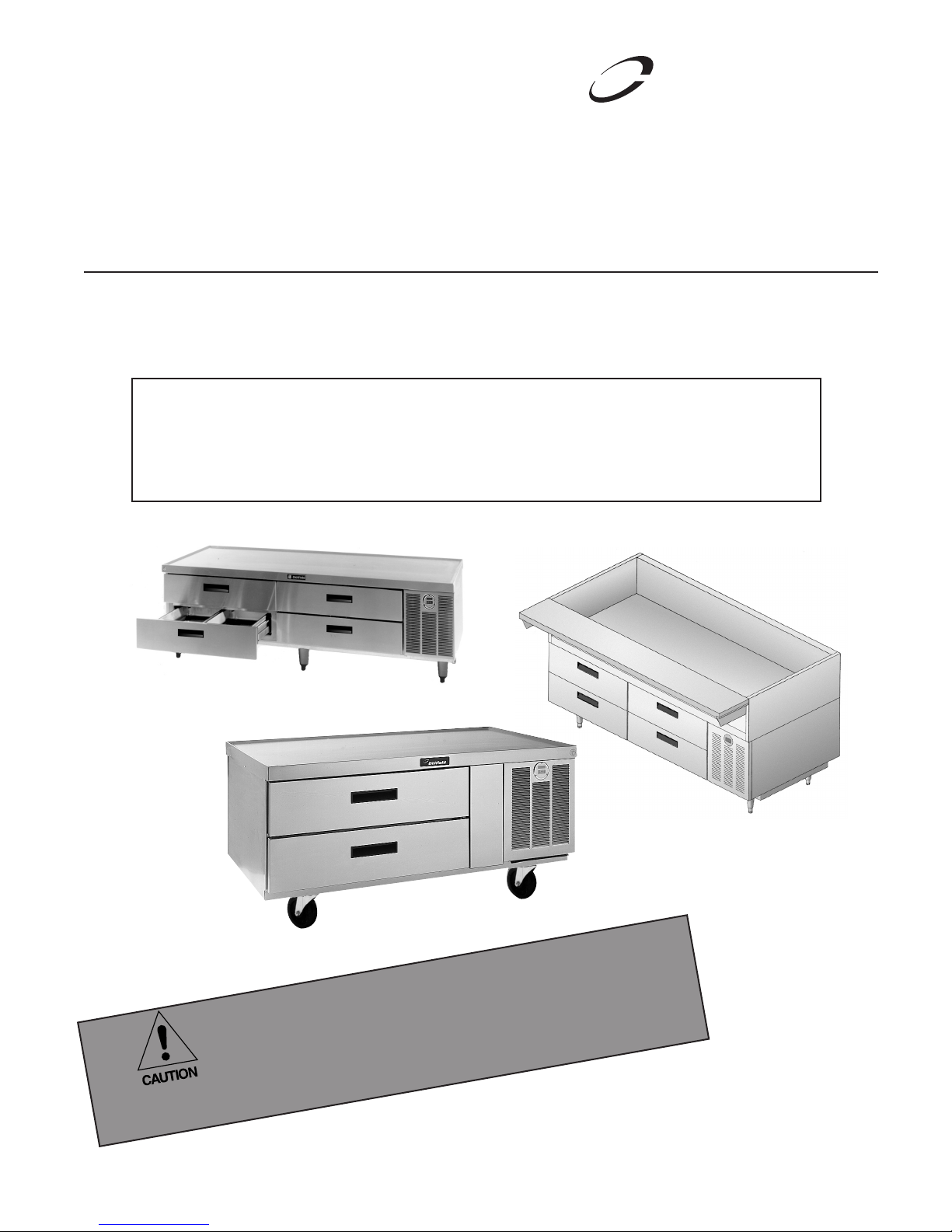
F2000 and F17 Series Equipment Stands
De lfield
™
®
Service, Installation and Care Manual
Please read this manual completely before attempting to install or operate this equipment! Notify carrier of
damage! Inspect all components immediately. See page 2.
Warning
To assure proper operation a 2" airspace must be maintained between the bottom of any cooking equipment
and the top of this unit. Cooking equipment must have a barrier (i.e. bottom, drip pan) between its heat
source and the top of the equipment stand. Failure to comply with this could severely damage the equipment
stand and void all warranties.
IMPORTANT INFORMATION
READ BEFORE USE
PLEASE SAVE THESE INSTRUCTIONS!
Effective Date December 2007
Page 2

F2000/F17 Series Equipment Stand Service and Installation Manual
Delfield
™
®
Contents Serial Number Location
RECEIVING AND INSPECTING ...................................................2
SPECIFICATIONS ................................................................... 3-4
INSTALLATION ....................................................................... 5-6
PRESSURE CONTROL SETTINGS .......................................... 6-7
OPERATION ........................................................................... 6-7
PARAGON TIME CLOCK DIAL ....................................................7
CARE AND CLEANING ...............................................................8
THERMOMETER .........................................................................8
WIRING DIAGRAMS ..................................................................9
WALL ANCHOR ASSEMBLY .....................................................10
CONDENSING UNIT ASSEMBLY DRAWING .............................11
MULLION COIL ASSEMBLY DRAWINGS
REMOTE REFRIG. .................................................................12
SELF CONTAINED REFRIG. ...................................................13
FREEZERS ............................................................................14
DOOR ASSEMBLY ....................................................................15
DRAWER ASSEMBLY DRAWING .............................................15
REPLACEMENT PARTS ...................................................... 16-17
STANDARD WARRANTIES ................................................. 18-20
NOTES ............................................................................... 21-23
The serial number on remote models is located behind the 6"
(15.2 cm) stainless steel panel.
The serial number on self-contained models is located in the
compressor housing.
The serial number tag shows the refrigerant used and the
amount of charge and amperage.
Always have the serial number of your unit available when calling for parts and service.
©2007 The Delfield Company. All rights reserved. Reproduction without written permission is prohibited. “Delfield” is a registered trademark of The Delfield Company.
Receiving and Inspecting the Equipment
Even though most equipment is shipped crated, care should
be taken during unloading so the equipment is not damaged
while being moved into the building.
1. Visually inspect the exterior of the package and skid or
container. Any damage should be noted and reported to
the delivering carrier immediately.
2. If damaged, open and inspect the contents with the
carrier.
3. In the event that the exterior is not damaged, yet upon
opening, there is concealed damage to the equipment
notify the carrier. Notification should be made verbally as
well as in written form.
4. Request an inspection by the shipping company of the
damaged equipment. This should be done within 10 days
from receipt of the equipment.
5. Check the lower portion of the unit to be sure legs or
casters are not bent.
6. Also open the compressor compartment housing and
visually inspect the refrigeration package. Be sure lines
are secure and base is still intact.
7. Freight carriers can supply the necessary damage forms
upon request.
8. Retain all crating material until an inspection has been
made or waived.
Uncrating the Equipment
First cut and remove the banding from around the crate.
Remove the front of the crate material, use of some tools will
be required. If the unit is on legs remove the top of the crate
as well and lift the unit off the skid. If the unit is on casters it
can be "rolled" off the skid.
2
For customer service, call (800) 733-8829, (800) 733-8821, Fax (989) 773-3210, www.delfield.com
Page 3
F2000/F17 Series Equipment Stand Service and Installation Manual
Delfield
™
®
Specifications
MODEL # OF # OF VOLTAGE/ NEMA BTU BTU EVAP. CAP.
NUMBER PANS DRAWERS HERTZ/PHASE AMPS H.P. PLUG WEIGHT LOAD SYSTEM BTU
Low-Profile Freezer Base Equipment Stands
F2748 4 2 115/60/1 10.0 1/2* N/S 295 1032 — 160
F2776 8 4 115/60/1 10.0 3/4* N/S 375 1770 — 160
F2660 4 2 115/60/1 12.0 1/2 5-15P 418 925 1776 —
F2694 8 4 115/60/1 16.0 3/4 5-20P 500 1558 2713 —
*Recommended horsepower N/S=Not Supplied, unit must be hard wired
12x20 RECOMMENDED NEMA BTU EVAP CAP
# OF PANS VOLTS AMPS H.P. PLUG WEIGHT LOAD BTU
Low-Profile Refrigerator Base Equipment Stands
REMOTE
F2852 4 115/60/1 3.0 1/5 N/S 278 461 120
F2856 4 115/60/1 3.0 1/5 N/S 299 461 120
F2862 6 115/60/1 3.0 1/5 N/S 331 518 120
F2875 8 115/60/1 6.0 1/4 N/S 401 717 120
F2880 8 115/60/1 6.0 1/4 N/S 428 726 240
F2887 10 115/60/1 6.0 1/4 N/S 466 859 240
F2899 12 115/60/1 6.0 1/3 N/S 530 973 240
F28110 12 115/60/1 6.0 1/3 N/S 588 1143 240
MODEL 12x20 NEMA BTU BTU EVAP CAP
NUMBER # OF PANS VOLTS AMPS H.P. PLUG WEIGHT LOAD SYSTEM BTU
SELF CONTAINED
F2952C 4 115/60/1 8.0 1/5 5-15P 418 461 1727 NA
F2956C 4 115/60/1 8.0 1/5 5-15P 439 461 1727 NA
F2962C 6 115/60/1 8.0 1/5 5-15P 487 518 1727 NA
F2975C 8 115/60/1 10.0 1/4 5-15P 589 717 2341 NA
F2980C 8 115/60/1 10.0 1/4 5-15P 600 726 2341 NA
F2987C 10 115/60/1 10.0 1/4 5-15P 637 859 2341 NA
F2999C 12 115/60/1 12.0 1/3 5-15P 725 973 2341 NA
F29110C 12 115/60/1 12.0 1/3 5-15P 744 1143 2341 NA
MODEL NUMBER SHELF MODEL
NUMBER OF SHELVES SQUARE FEET LENGTH WEIGHT
Open Shelf Equipment Stands
F17OS36 1 5.6 36” (91.4cm) 200
F17OS48 1 7.6 48” (121.9cm) 250
F17OS60 1 9.6 60” (152.4cm) 300
F17OS72 1 11.6 72” (182.9cm) 350
F17OS84 1 13.6 84” (213.4cm) 400
F17OS96 1 15.7 96” (243.8cm) 475
MODEL NUMBER 12 X 20 X 6 MODEL
NUMBER OF DRAWERS PAN CAPACITY LENGTH WEIGHT
Dry Drawer Equipment Stands
F17DD32 (1) 32” 2 32" (81.28cm) 290
F17DD46 (1) 19” & (1) 27” 3 46" (116.84cm) 350
F17DD54 (2) 27” 4 54" (137.16cm) 390
F17DD64 (2) 32” 4 64" (162.56cm) 430
F17DD73 (1) 19” & (2) 27” 5 73" (185.42cm) 475
F17DD81 (3) 27” 6 81" (205.74cm) 520
F17DD96 (3) 32” 6 96" (243.84cm) 600
For customer service, call (800) 733-8829, (800) 733-8821, Fax (989) 773-3210, www.delfield.com
3
Page 4
F2000/F17 Series Equipment Stand Service and Installation Manual
Delfield
™
®
Specifications
MODEL NUMBER OF NUMBER OF VOLTS/HERTZ/ NEMA BTU DESIGN BTU SYSTEM
NUMBER PANS DRAWERS PHASE AMPS H.P. PLUG WEIGHT LOAD CAPACITY
Self-Contained Refrigerated Base Equipment Stands
F17C52 (2) 32” 4 115/60/1 8.0 1/5 5-15P 410 452 1727
F17C60 (2) 19” & (2) 27” 6 115/60/1 8.0 1/5 5-15P 460 556 1727
F17C68 (4) 27” 8 115/60/1 8.0 1/5 5-15P 500 632 1727
F17C78 (4) 32” 8 115/60/1 8.0 1/5 5-15P 580 726 1727
F17C87 (2) 19” & (4) 27” 10 115/60/1 10.0 1/4 5-15P 625 868 2341
F17C95 (6) 27” 12 115/60/1 10.0 1/4 5-15P 700 1001 2341
F17C110 (6) 32” 12 115/60/1 12.0 1/3 5-15P 750 1143 2341
*12” X 20” X 4” deep pans, supplied and installed by others.
MODEL NUMBER OF PAN* RECOMMENDED VOLTS/HERTZ/ BTU DESIGN EVAP. CAP.
NUMBER DRAWERS CAPACITY HP PHASE AMPS LOAD BTU WEIGHT
Remote Refrigerated Base Equipment Stands
F17R44 (2) 32” 4 1/5 115/60/1 3.0 452 120 300
F17R52 (2) 19” & (2) 27” 6 1/5 115/60/1 3.0 556 120 350
F17R60 (4) 27” 8 1/5 115/60/1 3.0 632 120 396
F17R70 (4) 32” 8 1/5 115/60/1 3.0 726 120 450
F17R79 (2) 19” & (4) 27” 10 1/4 115/60/1 6.0 868 240 525
F17R87 (6) 27” 12 1/4 115/60/1 6.0 1001 240 560
F17R102 (6) 32” 12 1/3 115/60/1 6.0 1143 240 610
*12” X 20” X 4” deep pans, supplied and installed by others.
MODEL NUMBER OF PAN* VOLTS/HERTZ/ NEMA BTU DESIGN BTU SYSTEM
NUMBER DRAWERS CAPACITY H.P. PHASE AMPS PLUG LOAD CAPACITY WEIGHT
Self-Contained Freezer Base Equipment Stands
F17FC60 (2) 32” 4 1/2 115/60/1 12.0 5-15P 1242 1776 450
F17FC76 (2) 19” & (2) 27” 6 3/4 115/60/1 16.0 5-20P 1461 2713 600
F17FC84 (4) 27” 8 3/4 115/60/1 16.0 5-20P 1647 2713 635
F17FC94 (4) 32” 8 3/4 115/60/1 16.0 5-20P 1879 2713 710
*12” X 20” X 4” deep pans, supplied and installed by others.
MODEL NUMBER OF PAN* RECOMMENDED VOLTS/HERTZ/ BTU DESIGN EVAP. CAP.
NUMBER DRAWERS CAPACITY HP PHASE AMPS LOAD BTU WEIGHT
Remote Freezer Base Equipment Stands
F17FR48 (2) 32” 4 1/2 115/60/1 10.0 1242 160 360
F17FR58 (2) 19” & (2) 27” 6 3/4 115/60/1 10.0 1461 160 400
F17FR66 (4) 27” 8 3/4 115/60/1 10.0 1647 160 475
F17FR76 (4) 32” 8 3/4 115/60/1 10.0 1879 160 560
*12” X 20” X 4” deep pans, supplied and installed by others.
4
For customer service, call (800) 733-8829, (800) 733-8821, Fax (989) 773-3210, www.delfield.com
Page 5
Delfield
™
®
Installation
C A U T I O N
Location
This unit is intended for indoor use only. Be sure the location chosen
has a floor strong enough to support the total weight of the cabinet,
cooking equipment and contents. Re in force the floor as necessary to
provide for maximum loading, for complete weight chart, please refer to
page 7.
Good refrigeration is based on good air circulation inside and out.
Inside cabinet: Do not pack refrigerator so full that air cannot circulate.
Outside cabinet: Be sure that the unit has access to ample air to and
from the unit. If air flow is available to the rear of the unit that will help
dissipate exhaust air. In the event the unit is attached to the wall mount
brackets, it is important that air flow is available to the compressor
compartment. Allow air flow to the bottom of the unit as well, avoid hot
corners when possible. Allowing for the proper air flow and ventilation
to the compressor compartment will extend the life of the compressor as
well as ensure proper operation.
Cooking Equipment: WARNING! To assure proper operation a 2"
airspace must be maintained between the bottom of any cooking
equipment and the top of this unit. Cooking equipment must have
a barrier (i.e. bottom, drip pan) between its heat source and the top
of the equipment stand. Failure to comply with this could severely
damage the equipment stand and void all warranties.
Leveling
A level cabinet looks better and will perform better because the drain
pan will drain properly, the doors will line up with the frames properly,
and the cabinet will not be subject to undue strain.
A unit on legs will have an adjustable bullet foot on each leg, adjust
each for a level unit. A unit on casters will not be adjustable. Be sure
the unit is on a level floor, make necessary changes to the floor for
proper level.
Lock all front casters to ensure the stability of the unit.
Wall bracket installation
A wall bracket kit is supplied to secure the equipment stand to an
interior wall.
The wall bracket must be installed properly and the
equipment stand firmly secured to it before using
this unit! Failure to observe this warning may result
in damage to the equipment and/or injury to the
operator! Never use the drawers as steps!
Do not overload the drawers or drop or throw product into the drawer
pans.
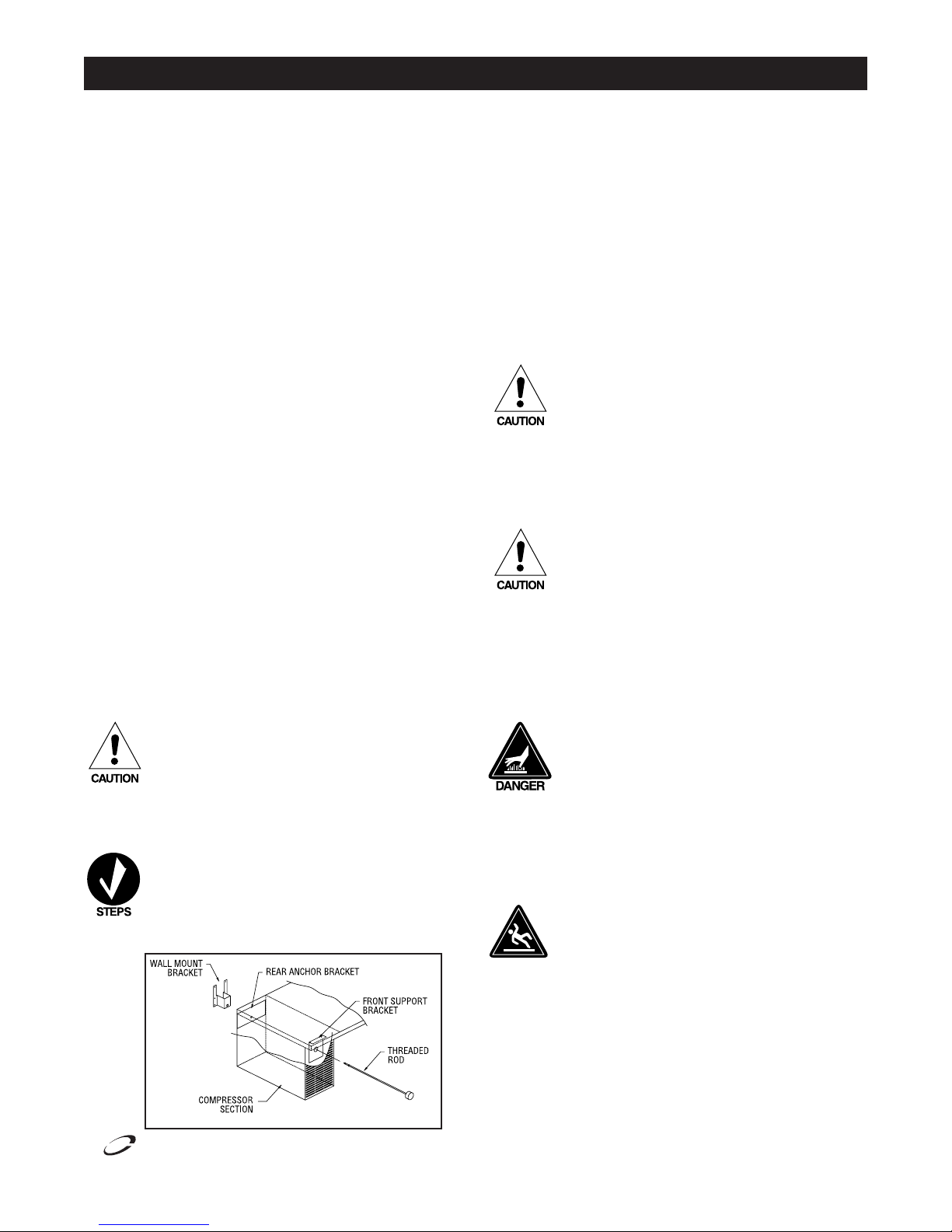
To install the wall bracket, follow these instructions:
1) Place the threaded rod through the front and rear
brackets in the compressor section (see diagram #1).
Thread the rod into the wall bracket, making sure the
longer bracket tabs are above the height of the unit.
2) Tighten the rod until the bracket is held snug against
the back of the unit.
Diagram #1.
Installation
of wall
bracket kit
See page 9
for part #'s
F2000/F17 Series Equipment Stand Service and Installation Manual
3) Move the unit against the wall at the desired location.
4) Secure the wall mount bracket to the wall using the top two holes
provided in the bracket tabs exposed above the unit.
The wall material must be capable of supporting a minimum load of
300 pounds (136 kilograms) in the vertical direction. All screws must
be 1/4" diameter and be capable of transferring the load from the
bracket to the wall.
5) Remove the threaded rod from the wall mount bracket and move the
unit away from the wall, leaving the bracket attached to the wall.
6) Secure the bracket to the wall using the remaining four holes.
7) Move the unit back into place and thread the rod back into the wall
mount bracket.
8) The unit should now be secured to the wall. Test the mounting by
pulling on the unit and checking that all screws are tightened and the
unit is firmly in place. If the unit is secured, you may now place other
equipment on top of the stand and use the unit as required.
Never place any equipment on top of this unit without
first installing the wall bracket as shown above and
ensuring that the equipment is securely anchored and
stable.
9) To remove the unit in order to clean behind it, first remove any
equipment placed on top of the stand. Then rotate the knob on the
threaded rod counter-clockwise to loosen and remove the rod from the
bracket.
Before removing any cooking equipment (including
cooking oils) from the equipment stand, allow time for
the equipment to cool thoroughly. Use extreme care in
moving cooking equipment.
The threaded rod must be reinstalled and tightened
before returning the unit to service!
Some models are supplied on optional casters. These units must also
have the wall bracket installed during use. Equipment stands have a
standard marine edge top.
Be sure all cooking equipment resting on the
equipment stand is properly anchored. Consult the
manufacturer’s instructions for the cooking equipment
to determine the proper mounting technique. It is
the owner’s and operator’s responsibility to securely
anchor cooking equipment to the equipment stand.
Plumbing
Self-contained equipment stands come standard with a condensate
evaporator. If the condensate evaporator fails, the unit’s drain must
have an outlet to an appropriate drainage area or container.
Moisture collecting from improper drainage can
create a slippery surface on the floor and a hazard
to employees. It is the owner’s and operator’s
responsibility to provide a con tain er or outlet for
drainage.
For customer service, call (800) 733-8829, (800) 733-8821, Fax (989) 773-3210, www.delfield.com
5
Page 6
F2000/F17 Series Equipment Stand Service and Installation Manual
Delfield
™
®
Installation — Continued
Electrical connection
Refer to the amperage data on page 3 & 4, the serial tag, your
local code or the National Electrical Code to be sure the unit
is connected to the proper power source. A protected circuit
of the correct voltage and amperage must be run for con nection of the line cord, or permanent connection to the unit.
Operation: Refrigerated Base Equipment Stands
The on/off switch must be turned to OFF and
the unit disconnected from the power source
whenever performing service, maintenance
functions or cleaning the refrigerated area.
Under no circumstances is a self-contained
unit be operated without the louvered panel in
place.
Drawer base equipment stands are designed and pre-set at the
factory to maintain a temperature of 36°F to 40°F (2°C to 4°C).
A solar-powered digital thermometer is located on the front of
the unit to allow monitoring of the drawer housing temperature.
Pressure Control Settings
The drawer housing temperature is controlled by a pressure
control located in the machine compartment.
Minor adjustments can be made to the pressure
control setting by turning the knob in a clockwise
direction for a colder temperature or counter
clockwise for a warmer temperature. In attempting to adjust the pressure control, you can do
damage to your unit by accidentally adjusting the
differential. If you are uncertain of this procedure, we strongly recommend that adjustments
be made by a qualified service agent. Delfield is
not responsible for charges incurred while having
the pressure control adjusted.
Operation: Freezer Base Equipment Stands
Freezer base equipment stands are designed and pre-set at the
factory to maintain a temperature of 0° F (-18° C) to -5° F (-21°
C) interior cabinet temperature at 100° F (38° C) ambient room
temperature. Self-contained units have a digital thermometer
installed in the removable louver. The digital thermometer for
remote units is located in the removable access panel.
Freezers use a Paragon time clock dial (see page 7) for
automatic defrosting of the evaporator coil. See below for
instructions on setting the time of day and general operating
instructions.
T
o Set Time of Day:
Turn the knob of the Paragon time clock dial in the center of the
inner (2 hour) dial and rotate it in a counter-clockwise di rec tion.
This will rotate the outer dial. Continue turning until the correct
time of day on the outer dial lines up with the time pointer.
Operation of Paragon Timer:
The Paragon timer is preset at the factory to provide four defrosts
per day at 6:00 am., 12:00 pm, 6:00 pm and 12:00 mid night. If
it is nec es sary to change the number of de frosts due to unusual
operating conditions it can be accomplished by placing the pins in
the outer dial at the appropriate time of day that defrost initiation is
desired.
Continuous opening and closing of the drawers will hamper the
unit’s ability to maintain optimum refrigeration temperature.
Excess weight on top of the unit will adversely affect the operation of the drawers.
The cooling coil is coated in epoxy to provide long-lasting
service. However, storing all acidic items, such as peppers and
tomatoes with lids that are sealable and immediately wiping up
all spills of either acid or base items will greatly extend the life
of your unit.
Never stand on the unit or its drawers! They are
not designed to hold the weight of an adult, and
may collapse or unit may tip if misused in this
manner.
These units use HFC-404A refrigerant and have a
lock-out high pressure limiting device. Under severe
overloading conditions, in the event of a condenser
fan failure or a plugged or blocked condenser, this
device may shut down the refrigeration system.
When the defrost control goes into defrost, power to the
condensing unit and evap o ra tor fans is in ter rupt ed, and the
defrost heater is energized. The defrost heater warms the
evaporator coil thereby melting all frost ac cu mu lat ed during
the previous refrigeration cycle. Once all frost is eliminated, the
temperature of the coil continues to rise until it reaches 70°F
(27°C). When this temperature is sensed by the defrost limit
control, the defrost control switches to refrigeration mode.
If for any reason the timer remains in defrost for a period of
time greater than 40 minutes, a back-up defrost termination is
also provided.
This back-up is an integral part of the time clock and is set at
the factory at 40 min utes.
It can be changed in the field as fol lows: push down and rotate
pointer on inside (2 hour) dial until it is opposite desired time
period (in min utes).
Caution: Even under the most severe op er at ing con di tions, it
should not be necessary to set the back-up time greater than
60 min utes. Consult the factory if com plete de-icing of the coil
is not ac com plished within this time pe ri od.
6
For customer service, call (800) 733-8829, (800) 733-8821, Fax (989) 773-3210, www.delfield.com
Page 7

Delfield
™
®
Pressure Control Settings
Part # 2193927
Factory recommended low-pressure control settings are:
HFC-404A refrigerators: 85# cut-in and 65# cut-out to main-
tain approximate interior temperature of 38°F.
Differential setting of 20#.
HFC-404A freezers: 32# cut-in and 8# cut-out to main-
tain approximate interior temperature of 0°F to 5°F.
Differential setting of 24#.
Pressure control settings are measured in pounds,
not fahrenheit.
F2000/F17 Series Equipment Stand Service and Installation Manual
Paragon 8145 Time Clock Dial
Part # 2194151
— used on F26 and F27, only
Note: The time clock dial is accessible by removing the
larger plate of the electrical box located behind the removable louver.
Maximum Cooking Equipment Weight Capacity
MODEL TOTAL WEIGHT UNIT WEIGHT DRAWER CAPACITY
F2952C 1200 389 150 652
F2956C 1200 405 150 645
F2962C 1200 479 300 421
F2975C 1800 540 300 960
F2980C 1800 578 300 922
F3987C 1800 672 450 678
F2999C 1800 691 450 659
F29110C 1800 766 450 584
F2660C 1200 418 150 632
F2694C 1800 505 300 995
CAUTION: RISK OF
ELECTRICAL SHOCK
Removing of top panel or timer
cover may expose live electrical
parts. Disconnect power supply
before servicing.
MAX COOKING
EQUIPMENT WEIGHT
For customer service, call (800) 733-8829, (800) 733-8821, Fax (989) 773-3210, www.delfield.com
7
Page 8

F2000/F17 Series Equipment Stand Service and Installation Manual
Delfield
™
®
Care and Cleaning
Stainless Steel Care and Cleaning
To prevent discoloration of rust on stainless steel several important
steps need to be taken. First, we need to understand the properties of
stainless steel. Stainless steel contains 70- 80% iron, which will rust.
It also contains 12-30% chromium, which forms an invisible passive
film over the steels surface, which acts as a shield against corrosion.
As long as the protective layer is intact, the metal is still stainless.
If the film is broken or contaminated, outside elements can begin to
breakdown the steel and begin to form rust of discoloration. Proper
cleaning of stainless steel requires soft cloths or plastic scouring pads.
the condenser coils. The condenser coil may require a spray with the
degreasing agent and then blown through with compressed air. Failure
to maintain a clean condenser coil can initially cause high temperatures
and excessive run times, continuous operation with dirty or clogged
condenser coils can result in compressor failures. Neglecting the
condenser coil cleaning procedures will void any warranties associated
with the compressor or cost to replace the compressor.
Never use a high-pressure water wash for this
cleaning procedure as water can damage the electrical
components located near or at the condenser coil.
NEVER USE STEEL PADS, WIRE BRUSHES OR SCRAPERS!
Cleaning solutions need to be alkaline based or non-chloride cleaners.
Any cleaner containing chlorides will damage the protective film of
the stainless steel. Chlorides are also commonly found in hard water,
salts, and household and industrial cleaners. If cleaners containing
chlorides are used be sure to rinse repeatedly and dry thoroughly upon
completion. Routine cleaning of stainless steel can be done with soap
and water. Extreme stains or grease should be cleaned with a nonabrasive cleaner and plastic scrub pad. It is always good to rub with the
grain of the steel. There are also stainless steel cleaners available which
can restore and preserve the finish of the steels protective layer. Early
signs of stainless steel breakdown can consist of small pits and cracks.
If this has begun, clean thoroughly and start to apply stainless steel
cleaners in attempt to restore the passivity of the steel.
Never use an acid based cleaning solution! Many food
products have an acidic content, which can deteriorate
the finish. Be sure to clean the stainless steel surfaces
of ALL food products. Common items include, tomatoes,
peppers and other vegetables.
Cleaning the Condenser Coil
The condenser coil requires regular cleaning, recommended is every
90 days. In some instances though you may find that there is a large
amount of debris and dust or grease accumulated prior to the 90day time frame. In these cases the condenser coil should be cleaned
every 30 days. If the build up on the coil consists of only light dust
and debris the condenser coil can be cleaned with a simple brush,
heavier dust build up may require a vacuum or even compressed air to
blow through the condenser coil. If heavy grease is present there are
de-greasing agents available for refrigeration use and specifically for
In order to maintain proper refrigeration performance, the
condenser fins must be cleaned of dust, dirt and grease regularly.
It is recommended that this be done at least every three months.
If conditions are such that the condenser is totally blocked in three
months, the frequency of cleaning should be increased. Clean the
condenser with a vacuum cleaner or stiff brush. If extremely dirty, a
commercially available condenser cleaner may be required.
Drawer Gaskets and Slides
See page 14 for drawer assembly drawing.
Drawer gaskets should be cleaned as required to maintain their ability to
seal properly. Do not use sharp tools or knives to scrape the bellows as this
may tear the gasket and eliminate its ability to seal. A soft bristle brush and
solution of soap and water should be all that is required to keep the gaskets
clean. Do not use full strength degreasing agents on the gasket because
they could cause the gasket to become brittle and crack.
The stainless steel drawer system including the drawer boxes, intermediate tracks and exterior tracks should be kept free of food and debris. The
intermediate tracks (the track containing all the rollers) are designed to be
removable without tools and are dishwasher safe. They can also be cleaned
in a sink with detergents and a soft bristle brush. The drawer box which
includes the stainless steel front and gasket are also removable without
tools and should be wiped clean of food and debris. Tracks and drawer
boxes should be cleaned on a daily basis for optimum performance.
Preventing Blower Coil Corrosion
To help prevent corrosion of the blower coil, store all acidic items, such as
peppers and tomatoes, in sealable containers. Immediately wipe up all spills of
items.
Thermometer
Part # 3516059
Thermometer Control Switch
To calibrate control or switch from °F to °C follow these steps.
Remove two screws and rear cover plate from thermometer.
Reposition °F/°C switch to desired setting. Insert probe into an
ice water bath. Ensure ice water temp is at 32°F or 0°C. Adjust
calibration screw to proper display temperature. Reinstall rear
cover and screws.
8
For customer service, call (800) 733-8829, (800) 733-8821, Fax (989) 773-3210, www.delfield.com
Page 9

F2000/F17 Series Equipment Stand Service and Installation Manual
Delfield
™
®
'.,
/./&&
37)4#(
02%3352%
#/.42/,
#//,).'&!.3
#/.$%.3).'5.)4
./4%7)2).'&/2
&3%2)%32%-/4%
).#,5$%3*5.#4)/."/8
7)4(,%!$3&/2&)%,$
#/..%#4)/.!.$7)2).'
4/%6!0/2!4/2&!.3!.$
#/),3/.,9
4)-%2
8
.
4)-%#,/#+
8
&
(
.
0520,%
/2!.'%
2%$
7()4%
&!.
&!.
$%&2/34
(%!4%2
&!.
$%,!9
$%&2/344%2-).!4)/.
"2/7.
",!#+
7()4%
2%$
$%&2/34
,)-)4
#//,).'
5.)4
#/.$%.3).'
5.)4
",!#+
02%3352%
#/.42/,
",!#+
/2!.'%
7()4%
",!#+
",!#+
7()4%
$//2(%!4%2
/.%0%2$//2
*"/8
7()4%
",!#+
4/0/7%23500,9
6(Z
",!#+
7()4%
30$4
37)4#(
*"/8
%6!0/2!4/2#/),!33%-",9
./4%7)2).'&/2
3%2)%32%-/4%
).#,5$%3*5.#4)/."/8
7)4(,%!$3&/2&)%,$
#/..%#4)/.!.$7)2).'
4/%6!0/2!4/2&!.3!.$
#/),3/.,9
#/.$%.3).'5.)4!.$
02%3352%#/.42/,7),,
"%2%0,!#%$7)4(
3/,%./)$6!,6%!.$
4(%2-/34!4
Wiring Diagram: F2900 & F17 Series Refrigerators 115V/60HZ/1PH
Wiring Diagram: F2600 & F17 Series Freezers
G
For customer service, call (800) 733-8829, (800) 733-8821, Fax (989) 773-3210, www.delfield.com
9
Page 10

F2000/F17 Series Equipment Stand Service and Installation Manual
Delfield
™
®
6
7
2
1
3
4
5
COMPRESSOR PAN
FRONT LOUVER
Wall Anchor Assembly
DELFIELD
KEY PART# DESCRIPTION
1 GMK00220 Rear anchor bracket (F2660 frzr)
GMK00221 Rear anchor bracket (F2694 frzr)
GMK00049 Rear anchor bracket (F2700 & F2800)
GMK00219 Rear anchor bracket (F2900 & all F17’s)
2 GMK00050 Front anchor support bracket
3 9321271 Threaded rod, 1/2-13 x 27” long
4 9321312 Retainer nut, 1/2 -13
5 SMK00166 Wall mounting bracket
6 9321122 Snap bushing, 1.50”
7 3234701 Handle
Complete Wall Anchor Assembly
XMK00086 F2660
XMK00087 F2694
XMK00064 All F2700’s & F2800’s
XMK00073 All F2900’s & F17’s
10
For customer service, call (800) 733-8829, (800) 733-8821, Fax (989) 773-3210, www.delfield.com
Page 11

F2000/F17 Series Equipment Stand Service and Installation Manual
Delfield
™
®
Mullion Coil Assembly: Remote Refrigerators
6
11
12
2
3
10
3
8
1
9
4
5
7
DELFIELD
KEY PART# DESCRIPTION
1 PMK00036 pan, drip, evap. coil, refg.
2 AMK00012 coil back
3 AMK00011 coil side
4 SMK00285 bracket, mounting, fan, evap, coil
5 3516173 guard, fan, 6.38” dia., lexan
6 3516095 coil, evap.
7 AMK00013 coil front
8 3516172 blade, fan 5.56, CCW, lexan, clear
9 2162691 motor, fan, 115V
10 3516273 valve, expansion, 1/4, hi, R-404A
11* 3516103 solenoid coil
12* 3516102 solenoid valve
13* 2194536 thermostat
* Remote units only.
13
XMK00107 EVAPORATOR COIL ASSEMBLY
Coil assembly is standard with above parts, less solenoid coil, solenoid valve
and thermostat.
Unit: F17C and F29 Series
XMK00108 EVAPORATOR COIL ASSEMBLY
Coil assembly is standard with above parts less the thermostat.
Unit: F17R102, F17R79, F17R87, F2887, F28102
XMK00109 EVAPORATOR COIL ASSEMBLY
Coil assembly is standard with above parts.
Unit: F17R and F28 Series
For customer service, call (800) 733-8829, (800) 733-8821, Fax (989) 773-3210, www.delfield.com
11
Page 12

F2000/F17 Series Equipment Stand Service and Installation Manual
Delfield
™
®
Mullion Coil Assembly: Self contained refrigerators
5
8
11
6
NOTE: Non-numbered items with ”‡” not
sold separately — available only with
complete assembly.
10
3
4
1
2
12
4
DELFIELD
KEY PART# DESCRIPTION
1 039-231-0000 pan, drip, evap. coil, refg.
‡ back coil
2 AMK00011 side, coil, w/fan
3 264-235-0000 bracket, mounting, fan, evap, coil
4 351-6173 guard, fan, 6.38” dia., lexan
5 351-6095 coil, evap.
‡ front, coil
6 351-6172 blade, fan 5.56, CCW, lexan, clear
7 216-2692 motor, fan, 240V
8 932-1353 screw, #10 x 0.50,
9 218-3313 coil harness with solenoid
10 351-6273 valve, expansion, 1/4, hi, R-404A
11 932-1247 screw, machine, #10-32x37 long
12 932-1068 screw, #10 x .87”
12
For customer service, call (800) 733-8829, (800) 733-8821, Fax (989) 773-3210, www.delfield.com
THE FOLLOWING UNIT REQUIRES A MULLION COIL ASSEMBLY
WITH SOLENOID (XMK00108):
DO000A03 (99”)
Using the key and part number listing at left:
Add part# 351-6074 — solenoid coil
THE FOLLOWING UNIT REQUIRES A MULLION COIL ASSEMBLY
WITH SOLENOID AND THERMOSTAT (XMK00109):
DO000A03 (99”)
Using the key and part number listing at left:
Add part# 219-4224-thermostat.
Add part# 351-6103-solenoid coil.
Add part# 351-6102-solenoid valve.
Page 13

Delfield
™
®
Mullion Coil Assembly: Freezers
F2000/F17 Series Equipment Stand Service and Installation Manual
Used on: F2660, F2694, F2748, F2776, F17FC60, F17FC76,
F17FC84, F17FC94, F17FR48, F17FR58, F17FR66 & F17FR76
NOTE: Non-numbered items with ”+” not
sold seperately — available only with
complete assembly — XMK00061.
10
8
DELFIELD
KEY QUANTITY PART# DESCRIPTION
1 1 SMK00162 pan, drip, freezer mullion coil
‡ 1 AMK00004 back, evap, housing
2 1 AMK00002 side, evap. HSNG., LH
3 2 AMK00005 bracket, fan motor, blower coil
4 1 3516073 coil, evap., freezer
5 1 2194034 heater, defrost
‡ 1 AMK00000 front, evap, housing
6 1 2183310 harness, coil, freezer, male
7 2 2162691 motor, fan, 115V, 50/60
8 2 3516173 guard, fan, 6.38” dia, lexan
9 2 3516172 blade, fan, 5.56, CCW, lexan
10 21 9321353 screw, #10x0.50
11 4 9321247 screw, machine, #10
12 4 9321238 screw, #8x.75
13 1 9321131 screw #10 x .50
14 1 3516271 valve, expansion, 1/4, low, R-4040A
15 1 2194046 control, limit, fan delay/defrst (not shown)
16 Need to order drip pan to get 1” s/s drain (not shown)
11
12
9
7
2
3
‡
5
13
4
‡
16
2
1
For customer service, call (800) 733-8829, (800) 733-8821, Fax (989) 773-3210, www.delfield.com
13
Page 14

F2000/F17 Series Equipment Stand Service and Installation Manual
Delfield
™
®
12 34
Refrigerator Freezer Cartridge only Drawer box Divider Intermediate Intermediate
*Cartridge assy *Cartridge assy (no fronts, no mullions) Bar(s) Left Track Right Track
32" lo profile 000-aew-0030 000-aew-003a RF700100 000-333-0034 264-018-0032, 264-018-0034 3234504 3234492
27" lo profile 000-aew-0031 000-aew-003b RF700101 000-333-0035 264-018-0033 3234517 3234509
24" lo profile 000-aew-0032 000-aew-003c RF700102 000-333-0036 264-018-0036, 264-018-0037 3234504 3234492
19" lo profile 000-aew-0033 000-aew-003d RF700103 000-333-0037 **264-018-0038 3234504 3234492
5678 91011
Refrigerator Freezer Drawer front Drawer front Drawer front Drawer front Gasket
Mullion Mullion assy assy, top assy,middle assy, bottom
32" low profile 000-315-0033 000-315-003b 000-328-0033 na na na 1701197
27" low profile 000-315-0032 000-315-003a 000-328-0032 na na na 1701196
24" low profile 000-315-0031 000-315-0039 000-328-0031 na na na 1701195
19" low profile 000-315-0030 000-315-0038 000-328-0030 na na na 1701194
6
6
1
4
2
3
5
5
Low Profile Refrigerated Drawer Assembly (32” Shown)
Cartridge Style Drawer Systems
Complete cartridge assembly includes: cartridge, drawer
boxes, drawer fronts, and mullion.
**264-018-0038: Divider bar can also be used in all
drawer boxs for 1/6 size pan applications.
Note: Drawer fronts, mullions, gaskets have not
changed, parts are included in Pro-E numbers only. Old
part numbers are still valid for parts and service.
Door Assembly: Low Profile
*OPTIONAL
DOOR
14
For customer service, call (800) 733-8829, (800) 733-8821, Fax (989) 773-3210, www.delfield.com
Low Profile
DELFIELD
KEY PART# DESCRIPTION
XMK00005 complete door assy. 19”, 18.75” x 15.72”
XMK00006 complete door assy. 24", 23.75" x 15.72"
XMK00007 complete door assy. 27”, 26.75” x 15.72”
1 1701187 gasket, door, 19”
1701188 gasket, door 24"
1701189 gasket, door, 27”
2 Not replaceable handle, snap-in, 7” (not replaceable)
3 3234214 hinge, door, top/LH, bottom/RH
4 3234218 hinge, door, top/RH, bottom/LH
5 3234391 hinge, door, L-shaped
6 9321107 bushing, nylon, hinge pin
NOTE: Indicate if door is left or right hinged when
ordering.
Page 15

Delfield
™
®
Parts Replacement
Low Profile Freezer Bases
Models F2660, F2694, F2748, F2776
Standard Parts
000-AEW-003A Drawer Cartridge Assembly 32”
XMK00061 Evaporator Coil Assembly
1701197 Drawer Gasket 32”
2183433 Mullion Heater
2194151 Defrost Timer
2194199 Condensate Heat Element
3234645 Leg
3234161 Caster (Optional)
3516059 Solar Digital Thermometer
XMK00065 Condensate Pan w/heater
Additional Parts
F2660
2183348 Cord/Plug Assembly
2193927 Low Pressure Control
3516101 Filter Drier
SMK00044 Louver Assembly 18”
F2694
2183348 Cord/Plug Assembly
2193927 Low Pressure Control
3516101 Filter Drier
SMK01059 Louver Assembly 24”
Low Profile Refrigerated Bases
Models F2800 Series
Standard Parts
1701000 Cutting Board Cap
2194199 Condensate Heat Element
3234161 Caster (Optional)
3234645 Leg
3516059 Solar Digital Thermometer
9321136 Cutting Board Pin
XMK00065 Condensate Pan W/Element
XMK00109 Evaporator Coil Assembly
Additional Parts
F2844 / F2852/ F2856/ F2880
000-AEW-0030 32” Drawer Cartridge Assembly
1701197 32” Drawer Gasket
F2862
1701194 19” Drawer Gasket
1701196 27” Drawer Gasket
000-AEW-0031 27” Low Profile Drawer Cartridge Assy.
000-AEW-0033 19” Low Profile Drawer Cartridge Assy.
F2875
000-AEW-0030 32” Drawer Cartridge Assembly
1701197 32” Drawer Gasket
000-AEW-0031 27” Low Profile Drawer Cartridge Assy.
1701196 27” Drawer Gasket
F2887
1701194 19” Drawer Gasket
1701196 27” Drawer Gasket
000-AEW-0031 27” Low Profile Drawer Cartridge Assy.
000-AEW-0033 19” Low Profile Drawer Cartridge Assy.
XMK00108 Evaporator Coil Assembly
F2899
1701196 27” Drawer
000-AEW-0031 27” Low Profile Drawer Cartridge Assy.
XMK00108 Evaporator Coil Assy.
F28102/F28110
XMK00108 Evaporator Coil Assy.
1701197 32” Drawer Gasket
000-AEW-0030 32” Low Profile Drawer Cartridge Assy.
XMK00109 Evaporator Coil Assy. W/T-stat
F2000/F17 Series Equipment Stand Service and Installation Manual
F2900 Series
Standard Parts
1701000 Cutting Board Pin
2183348 Cord/Plug Assy.
2193927 Low Pressure Control
3234161 Caster
3234645 Leg
3516059 Digital Thermometer
3516101 Filter Drier
XMK00107 Evaporator Coil Assy.
Additional Parts
F2952/F2952C
1701197 32” Drawer Gasket
000-AEW-0030 32” Low Profile Drawer Cartridge Assy.
SMK00043 Louver 14”
F2956/2956C
1701197 32” Drawer Gasket
000-AEW-0030 32” Low Profile Drawer Cartridge Assy.
SMK00044 Louver 18”
F2962/F2962C
1701194 19” Drawer Gasket
1701196 27” Drawer Gasket
000-AEW-0031 27” Low Profile Drawer Cartridge Assy.
000-AEW-0033 19” Low Profile Drawer Cartridge Assy.
SMK01112 Louver 16”
F2975/F2975C
1701196 27” Drawer Gasket
1701197 32” Drawer Gasket
000-AEW-0031 27” Low Profile Drawer Cartridge Assy.
000-AEW-0030 32” Low Profile Drawer Cartridge Assy.
SMK01112 Louver 16”
F2978/F2978C
1701197 32” Drawer Gasket
000-AEW-0030 32” Low Profile Drawer Cartridge Assy.
F2980/F2980C
1701197 32” Drawer Gasket
000-AEW-0030 32” Low Profile Drawer Cartridge Assy.
SMK01112 Louver 16”
F2987/F2987C
1701194 19” Drawer Gasket
1701196 27” Drawer Gasket
000-AEW-0031 27” Low Profile Drawer Cartridge Assy.
000-AEW-0033 19” Low Profile Drawer Cartridge Assy.
SMK00043 Louver 14”
F2996/F2996C/F2999/F2999C
1701196 27” Drawer Gasket
000-AEW-0031 27” Low Profile Drawer Cartridge Assy.
SMK00044 Louver 18”
F29110/F29110C
1701197 32” Drawer Gasket
000-AEW-0030 32” Low Profile Drawer Cartridge Assy.
SMK00043 Louver 14”
F17C Series
Standard Parts
1701000 Cutting Board Pin Cap
2183348 Cord/Plug Assembly
2193927 Low Pressure Control
3234161 Caster (Optional)
3234645 Leg
3516059 Digital Thermometer
3516101 Filter Drier
9321136 Pin For Cutting Board
XMK00107 Evaporator Coil Assembly
XMK00135 Cutting Board Bracket Assy, Left Hand
XMK00136 Cutting Board Bracket Assy, Right Hand
SMK00043 Louver 14”
Additional Parts
F17C52
1701197 32” Drawer Gasket
000-AEW-0030 32” Low Profile Drawer Cartridge Assy.
F17C60
1701196 27” Drawer Gasket
1701194 19” Drawer Gasket
F17C68
000-AEW-0031 27” Low Profile Drawer Cartridge Assy.
1701196 27” Drawer Gasket
000-AEW-0031 27” Low Profile Drawer Cartridge Assy.
000-AEW-0033 19” Low Profile Drawer Cartridge Assy.
F17C78
1701197 32” Drawer Gasket
000-AEW-0030 32” Low Profile Drawer Cartridge Assy.
F17C87
1701194 19” Drawer Gasket
1701196 27” Drawer Gasket
000-AEW-0031 27” Low Profile Drawer Cartridge Assy.
000-AEW-0033 19” Low Profile Drawer Cartridge Assy.
F17C95
1701196 27” Drawer Gasket
000-AEW-0031 27” Low Profile Drawer Cartridge Assy.
F17C110
1701197 32” Drawer Gasket
000-AEW-0030 32” Low Profile Drawer Cartridge Assy.
F17FC Series
Standard Parts
2183433 Mullion Heater
2183348 Cord/Plug Assembly
2193927 Low Pressure Control
2194151 Defrost Timer
2194199 Condensate Heat Element
3234161 Caster (Optional)
3234645 Leg
3516059 Digital Thermometer
3516101 Filter Drier
XMK00061 Freezer Evaporator Coil Assy.
XMK00065 Condensate Pan W/Element
XMK00135 Cutting Board Bracket Assy, Left Hand
XMK00136 Cutting Board Bracket Assy, Right Hand
Additional Parts
F17FC60
000-AEW-003A Drawer Gasket
SMK00044 Louver 18”
F17FC76
1701196 27” Drawer Gasket
1701194 19” Drawer Gasket
2183432 Heater Mullion Ð 19”
000-AEW-003B Drawer Cartridge Assembly 27”
000-AEW-003D Drawer Cartridge Assembly 19”
SMK01059 Louver 24”
F17FC84
1701196 27” Drawer Gasket
3526712 Condensing Unit ¾ HP, Low, R404A
000-AEW-003B Drawer Cartridge Assembly 27”
SMK01059 Louver 24”
F17FC94
1701197 Drawer Gasket
000-AEW-003A Drawer Cartridge Assembly 32”
SMK01059 Louver 24”
For customer service, call (800) 733-8829, (800) 733-8821, Fax (989) 773-3210, www.delfield.com
15
Page 16

F2000/F17 Series Equipment Stand Service and Installation Manual
Delfield
™
®
Parts Replacement - continued
F17R Series
Standard Parts
3234161 Caster (Optional)
3234645 Leg
3516059 Digital Thermometer
XMK00109 Evaporator Coil Assembly
XMK00135 Cutting Board Bracket Assy. Left
XMK00136 Cutting Board Bracket Assy. Right
Additional Parts
F17R44
1701197 32” Drawer Gasket
000-AEW-0030 32” Low Profile Drawer Cartridge Assy.
F17R52
1701194 19” Drawer Gasket
1701196 27” Drawer Gasket
000-AEW-0031 27” Low Profile Drawer Cartridge Assy.
000-AEW-0033 19” Low Profile Drawer Cartridge Assy.
F17R60
1701196 27” Drawer Gasket
000-AEW-0031 27” Low Profile Drawer Cartridge Assy.
F17R70
1701197 32” Drawer Gasket
000-AEW-0030 32” Low Profile Drawer Cartridge
Assembly
F17R79
1701194 19” Drawer Gasket
1701196 27” Drawer Gasket
000-AEW-0031 27” Low Profile Drawer Cartridge Assy.
000-AEW-0033 19” Low Profile Drawer Cartridge Assy.
XMK00108 Coil Assembly W/Solenoid
F17R87
1701196 27” Drawer Gasket
000-AEW-0031 27” Low Profile Drawer Cartridge Assy.
XMK00108 Coil Assembly W/Solenoid
F17R102
1701197 32” Drawer Gasket
000-AEW-0030 32” Low Profile Drawer Cartridge Assy.
XMK00108 Coil Assembly W/Solenoid
Standard Parts
F17FR Series
2183433 Mullion Heater 19”
2194151 Defrost Timer
2194199 Condensate Heat Element
3234161 Caster (Optional)
3234645 Leg
3516059 Solar Digital Thermometer
XMK00061 Freezer Coil Assembly
XMK00065 Condensate Pan w/element
XMK00135 Cutting Board Bracket Assy., Right Hand
Additional Parts
F17FR48
1701197 Drawer Gasket 32”
000-AEW-003A Drawer Cartridge Assy. 32”
F17FR58
1701194 19” Drawer Gasket
1701196 27” Drawer Gasket
2183432 Mullion Heater 19”
000-AEW-003B Drawer Cartridge Assy. 27”
000-AEW-003D Drawer Cartridge Assy. 19”
F17FR66
1701196 27” Drawer Gasket
000-AEW-003B Drawer Cartridge Assy. 27”
F17FR76
1701197 Drawer Gasket 32”
000-AEW-003A Drawer Cartridge Assy. 32”
F17DD Series
Standard Parts
3234645 Leg
3234161 Caster (Optional)
Additional Parts
F17DD32
000-188-0037 32” Single Dry Drawer Assy
F17DD46
000-188-0034 19” Single Dry Drawer Assy
000-188-0037 32” Single Dry Drawer Assy
F17DD54
000-188-0036 32” Single Dry Drawer Assy
F17DD64
000-188-0037 32” Single Dry Drawer Assy
F17DD73
000-188-0034 19” Single Dry Drawer Assy
000-188-0036 27” Single Dry Drawer Assy
F17DD81
000-188-0036 27” Single Dry Drawer Assy
F17DD96
000-188-0037 32” Single Dry Drawer Assy
F17OS Series
Standard Parts
3234645 Leg
3234161 Caster (Optional)
Cutting board 1 1/4 x 9 1/2 wide, call factory with
required length for price quote.
16
For customer service, call (800) 733-8829, (800) 733-8821, Fax (989) 773-3210, www.delfield.com
Page 17

F2000/F17 Series Equipment Stand Service and Installation Manual
Delfield
™
®
STANDARD WARRANTY -
The Delfield Company (“Delfield”) warrants to the Original Purchaser of the Delfield product (herein called the “Unit”) that such
Unit, and all parts thereof, will be free from defects in material
and workmanship under normal use and service for a period of
one (1) year from the date of shipment of the Unit to the Original Purchaser or, if the Original Purchaser returns the warranty card
completely filled out including the date of installation within thirty (30)
days of receipt of the Unit, one (1) year from the date of installation.
During this one year warranty period, Delfield will repair or replace
any defective part or portion there of returned to Delfield by the
Original Purchaser which Delfield determines was defective due to
faulty material or workmanship. The Original purchaser will pay all
labor, crating, freight and related costs incurred in the removal of
the Unit of defective component and shipment to Delfield, except
that during a period of either ninety (90) days from the date of
shipment of the Unit to the Original Purchaser or, if the Original
Purchaser returns the warranty card completely filled out including
the date of installation within thirty (30) days of receipt of the Unit,
ninety (90) days from the date of installation Delfield will pay all
related labor costs. Delfield will pay the return costs if the Unit or
part thereof was defective.
The term “Original Purchaser” as used herein means that person,
firm, association, or corporation for whom the Unit was originally
installed.
This warranty does not apply to any Unit or part thereof that has
been subjected to misuse, neglect, alteration, or accident, such as
accidental damage to the exterior finish, operated contrary to the
recommendations specified by Delfield; or repaired or altered by
anyone other than Delfield in any way so as to, in Delfield’s sole
judgement, affect its quality or efficiency. This warranty does not
apply to any Unit that has been moved from the location where
it was originally installed. This warranty also does not cover the
refrigerator drier or the light bulbs used in the Unit. The warranty
is subject to the user’s normal maintenance and care responsibility as
set forth in the Service and Installation Manual, such as cleaning the
condenser coil, and is in lieu of all other obligations of Delfield. Delfield
neither assumes, nor authorizes any other person to assume for Delfield,
any other liability in connection with Delfield’s products.
Removal or defacement of the original Serial Number or Model
Number from any Unit shall be deemed to release Delfield from all
obligations hereunder or any other obligations, express or implied.
One year parts, 90 days labor.
the right to replace the defective Unit with a complete Unit of the
same manufacturer or of another make. Unless authorized by
Delfield in writing, this warranty does not permit the replacement of
any part, including the motor-compressor, to be made with the part
of another make or manufacturer.
No claims can be made under this warranty for spoilage of any
products for any reason, including system failure.
The installation contractor shall be responsible for building access,
entrance and field conditions to insure sufficient clearance to allow
any hood(s), vent(s), or Unit(s) if necessary, to be brought into the
building. Delfield will not be responsible for structural changes
or damages incurred during installation of the Unit or any exhaust
system.
Delfield shall not be liable in any manner for any default or delay in
performance hereunder caused by or resulting from any contingency beyond Delfield’s control, including, but not limited to, war,
governmental restrictions or restraints, strike, lockouts, injunctions,
fire, flood, acts of nature, short or reduced supply of raw materials,
or discontinuance of the parts by the original part manufacturer.
Except as provided in any Additional Four Year Protection Plan, if
applicable, and the Service Labor Contract, if applicable, the foregoing
is exclusive and in lieu of all other warranties, whether written or oral,
express or implied. This warranty supersedes and excludes any prior oral
or written representations or warranties. Delfield expressly disclaims
any implied warranties of merchantability, fitness for a particular purpose
of compliance with any law, treaty, rule or regulation relating to the discharge of substances into the environment. The sole and exclusive remedies of any person relating to the Unit, and the full liability of Delfield
for any breach of this warranty, will be as provided in this warranty.
Other than this Delfield Standard One Year Limited Warranty, any
applicable Delfield Additional Four Year Protection Plan or applicable Delfield Service Labor Contract, the Original Purchaser agrees
and acknowledges that no other warranties are offered or provided
in connection with or for the unit or any other part thereof.
In no event will Delfield be liable for special, incidental or consequential damages, or for damages in the nature of penalties.
Parts furnished by suppliers to Delfield are guaranteed by Delfield
only to the extent of the original manufacturer’s express warranty to Delfield. Failure of the Original Purchaser to receive such
manufacturer’s express warranty to Delfield. Failure of the Original
Purchaser to receive such manufacturers warranty shall in no way
create any warranty, expressed or implied, or any other obligation
or liability on Delfield’s part in respect thereof.
If shipment of a replacement part is requested prior to the arrival in
the Delfield factory of the part claimed to be defective, the Original
Purchaser must accept delivery of the replacement part of a C.O.D.
basis, with credit being issued after the part has been received and
inspected at Delfield’s plant and determined by Delfield to be within
this warranty.
Under no condition does this warranty give the Original Purchaser
For customer service, call (800) 733-8829, (800) 733-8821, Fax (989) 773-3210, www.delfield.com
17
Page 18

F2000/F17 Series Equipment Stand Service and Installation Manual
Delfield
™
®
ADDITIONAL FOUR YEAR PROTECTION PLAN -
In addition to the Standard One Year Warranty on the Motor-Compressor contained in the above listed Delfield product (the “Unit”), The
Delfield Company (“Delfield”) also agrees to repair, or exchange with
similar or interchangeable parts in design and capacity at Delfield’s
option, the defective Motor-Compressor contained in the Unit (the
“Motor-Compressor), or any part thereof, for the Original Purchaser
only, at any time during the four (4) years following the initial one (1)
year period commencing on the date of installation for the Original
Purchaser. Failure of the Original Purchaser to register the registration
card containing the Original Purchasers name, address, date of installation,
model number and serial number of the Unit containing the Motor-Compressor within 30 days from the date of installation shall void this warranty.
This additional warranty is only available if the Motor-Compressor
is inoperative due to defects in material or factory workmanship,
as determined by Delfield in its sole judgement and discretion. The
Original Purchaser shall be responsible for returning the defective
Motor-Compressor to Delfield prepaid, F.O.B. at the address shown on
the back cover of this manual.
The term “Original Purchaser” as used herein means that person, firm,
association, or corporation for whom the Unit was originally installed.
The term “Motor-Compressor” as used herein does not include unit
base, air or water cooled condenser, receiver, electrical accessories
such as relay, capacitors, refrigerant controls, or condenser fan/motor
assembly. This warranty does not cover labor charges incidental to
the replacement of parts. This warranty further does not include
any equipment to which said condensing unit is connected, such as
cooling coils, temperature controls or refrigerant metering devices.
This warranty shall be void if the Motor-Compressor, in Delfield’s sole
judgement, has been subjected to misuse, neglect, alteration or accident, operated contrary to the recommendations specified by the Unit
manufacturer, repaired or altered by anyone other than Delfield in any
way so as, in Delfield’s sole judgment, to affect its quality or efficiency
or if the serial number has been altered, defaced or removed. This
Warranty does not apply to a Motor-Compressor in any Unit that has
been moved from the location where it was originally installed. The
addition of methyl chloride to the condensing unit or refrigeration
system shall void this warranty.
General Conditions
Delfield shall not be liable in any manner for any default or delay
in performance hereunder caused by or resulting from any contingency beyond Delfield’s control, including, but not limited to, war,
governmental restrictions or restraints, strike, lockouts, injunctions,
fire, flood, acts of nature, short or reduced supply of raw materials,
or discontinuance of any part or the Motor-Compressor by the unit
manufacturer.
Motor-Compressor by us during the four (4) year period. Delfield
shall replace the Motor-Compressor at no charge.
This warranty does not give the Original Purchaser of the MotorCompressor the right to purchase a complete replacement MotorCompressor of the same make or of another make. It further does
not permit the replacement to be made with a Motor-Compressor
of another kind unless authorized by Delfield. In the event Delfield
authorizes the Original Purchaser to purchase a replacement MotorCompressor locally, only the wholesale cost of the Motor-Compressor
is refundable.
Expressly excluded from this warranty are damages resulting from
spoilage of goods.
Except as provided in any applicable Standard One Year Limited Warranty
or applicable Service Labor Contract, the foregoing is exclusive and in lieu
of all other warranties, whether written or oral, express or implied. This
Warranty supersedes and excludes any prior oral or written representations or warranties. Delfield expressly disclaims any implied warranties
of merchantability, fitness for a particular purpose or compliance with any
law, treaty, rule or regulation relating to the Motor-Compressor, and the full
liability of Delfield for any breach of this warranty, will be as provided in
this warranty.
Other than any applicable Delfield Standard One year Limited Warranty, this Delfield Additional Four Year Protection Plan and any applicable Delfield Service Labor Contract, the Original Purchaser agrees
and acknowledges that no other warranties are offered or provided in
connection with or for the Motor-Compressor or any part thereof.
In no event will Delfield be liable for special, incidental or consequential damages, or for damages in the nature of penalties.
For motor compressor only.
Replacement of a defective Motor-Compressor is limited to one (1)
18
For customer service, call (800) 733-8829, (800) 733-8821, Fax (989) 773-3210, www.delfield.com
Page 19

F2000/F17 Series Equipment Stand Service and Installation Manual
Delfield
™
®
DRAWER WARRANTY -
The Delfield Company (“Delfield”) warrants to the Original Purchaser of the
Delfield drawer system (herein called the “Unit”) that such Unit, and all parts
thereof, will be free from defects in material and workmanship under normal
use and service for a period of one (1) year from the date of shipment of the
Unit to the Original Purchaser or, if the Original Purchaser returns the warranty card completely filled out including the date of installation within thirty
(30) days of receipt of the Unit, one (1) year from the date of installation. In
addition, Delfield warrants the left and right intermediate track deemed the
“Roller track assembly” profiles, this is the part that contains all the Delrin
rollers for ten years. These are the only parts falling under the 10 year warranty. During this one year warranty period, Delfield will repair or replace
any defective part or portion thereof returned to Delfield by the Original
Purchaser which Delfield determines was defective due to faulty material or
workmanship. The Original Purchaser will pay all labor, crating, freight and
related costs incurred in the removal of the Unit or defective component and
shipment to Delfield, except that during a period of either ninety (90) days
from the date of shipment of the Unit to the Original Purchaser or, if the
Original Purchaser returns the warranty card completely filled out including
the date of installation within thirty (30) days of receipt of the Unit, ninety
(90) days from the date of installation Delfield will pay all related labor costs.
Delfield will pay the return costs if the Unit or part thereof was defective.
The term “Original Purchaser” as used herein means that person, firm, association, or corporation for whom the Unit was originally installed.
This Warranty does not apply to any Unit or part hereof that has been subjected to misuse, neglect, alteration, or accident, such as accidental damage
to the exterior finish; operated contrary to the recommendations specified by
Delfield; or repaired or altered by anyone other than Delfield in any way so as
to, in Delfield’s sole judgment, affect its quality or efficiency. This Warranty
does not apply to any Unit that has been moved from the location where it
was originally installed. The warranty is subject to the user’s normal maintenance and care responsibility as set forth in the Service and Installation
Manual. Delfield neither assumes, nor authorizes any other person to assume
for Delfield, any other liability in connection with Delfield’s products.
One/ Ten Year Parts * 90 Day labor
Under no condition does this Warranty give the Original Purchaser the right
to replace the defective Unit with a complete Unit of the same manufacturer
or of another make. Unless authorized by Delfield in writing, this Warranty
does not permit the replacement of any part to be made with the part of
another make or manufacturer.
No claims can be made under this Warranty for spoilage of products for any
reason, including system failure.
Delfield shall not be liable in any manner for any default or delay in performance hereunder caused by or resulting from any contingency beyond
Delfield’s control, including, but not limited to, war, governmental restrictions
or restraints, strikes, lockouts, injunctions, fire, floods, acts of nature, short
or reduced supply of raw materials, or discontinuance of the parts by the
original part manufacturer.
Except as provided in any Additional Four Year Protection Plan, if applicable,
and the Service Labor Contract, if applicable, the foregoing is exclusive
and in lieu of all other warranties, whether written or oral, express or
implied. This Warranty supersedes and excludes any prior oral or written
representations or warranties. Delfield expressly disclaims any implied
warranties of merchantability, fitness for a particular purpose or compliance
with any law, treaty, rule or regulation relating to the discharge of substances
into the environment. The sole and exclusive remedies of any person relating
to the Unit, and the full liability of Delfield for any breach of this Warranty,
will be as provided in this Warranty.
Other than this Delfield Standard One Year Limited Warranty, any applicable
Delfield Additional Four Year Protection Plan or applicable Delfield Service
Labor Contract, the Original Purchaser agrees and acknowledges that no
other warranties are offered or provided in connection with or for the Unit or
any part thereof.
In no event will Delfield be liable for special, incidental or consequential
damages, or for damages in the nature of penalties.
Removal or defacement of the original Serial Number or Model Number from
any Unit shall be deemed to release Delfield from all obligations hereunder or
any other obligations, express or implied.
Parts furnished by suppliers to Delfield are guaranteed by Delfield only to the
extent of the original manufacturer’s express warranty to Delfield. Failure of
the Original Purchaser to receive such manufacturer’s warranty shall in no
way create any warranty, express or implied, or any other obligation or liability on Delfield’s part in respect thereof.
If shipment of a replacement part is requested prior to the arrival in the
Delfield factory of the part claimed to be defective, Delfield will send a UPS
call tag to the customer to receive damaged or defective parts back for
inspection. Delfield must receive the parts back to redeem warranty coverage from Fulterer. It is also very important to receive these parts to determine if any future change to the design is needed.
For customer service, call (800) 733-8829, (800) 733-8821, Fax (989) 773-3210, www.delfield.com
19
Page 20

980 S. Isabella Rd., Mt. Pleasant, MI 48858, U.S.A. • +1(989) 773-7981 or (800) 733-8829 • Fax (866) 779-2040 • www.delfield.com
Delfield reserves the right to make changes in design or specifications without prior notice. ©2007 The Delfield Company. All rights reserved. Printed in the U.S.A.
Delfield
™
®
Mt. Pleasant, MI
Covington, TN
Thank you for choosing Delfield!
Help is a phone call away! Help our team of professional, courteous customer service
reps by having your model number and serial number available at the time
of your call (800) 733-8829
Model: ________________________S/N: ____________________
Installation Date: ________________________________________
For a list of Delfield’s authorized parts depots,
visit our website at
www.delfield.com
DM2000/17 08/05
 Loading...