

Page 1
ASM Series
Service and Installation Manual
Please read this manual completely before attempting to install or operate this equipment!
Notify carrier of damage! Inspect all components immediately. See page 2.
ASM SERIES
Drop-In Air Screen Merchandisers
IMPORTANT INFORMATION
READ BEFORE USE
PLEASE SAVE THESE INSTRUCTIONS!
August 2011
Page 2
ASM Series Service and Installation Manual
Contents Serial Number Location
Serial Number Location ........................................................2
Receiving & Inspecting Equipment .......................................2
Specifications ........................................................................3
Installation ........................................................................ 4-5
Operation ..............................................................................6
Sliding Door Removal And Reinstall .....................................6
Night & Security Cover Operation .........................................6
Shelf Adjustments .................................................................7
Temperature Control Settings ...............................................7
Maintenance ..........................................................................8
Wiring Diagrams ............................................................. 9-11
Condensing Unit Assemblies ........................................ 12-13
Replacement Parts ........................................................ 13-15
Standard Labor Guidelines ..................................................16
Standard Warranties ..................................................... 17-18
Notes ..................................................................................19
The serial number on all self-contained Drop-In Air Screen
Merchandiser units is located on the mechanical section wall.
Always have the serial number of your unit available when calling
for parts or service. A complete list of authorized Delfield parts
depots is available at www.delfield.com.
©2011 The Delfield Company. All rights reserved. Reproduction without
written permission is prohibited.
Serial #
Model #
Installation Date:
Receiving And Inspecting The Equipment
Even though most equipment is shipped crated, care should be
taken during unloading so the equipment is not damaged while
being moved into the building.
1. Visually inspect the exterior of the package and skid or
container. Any damage should be noted and reported to
the delivering carrier immediately.
2. If damaged, open and inspect the contents with the carrier.
3. In the event that the exterior is not damaged, yet upon
opening, there is concealed damage to the equipment
notify the carrier. Notification should be made verbally as
well as in written form.
4. Request an inspection by the shipping company of the
damaged equipment. This should be done within 10 days
from receipt of the equipment.
5. Check the lower portion of the unit to be sure legs or
casters are not bent.
6. Also open the compressor compartment housing and
7. Freight carriers can supply the necessary damage forms
8. Retain all crating material until an inspection has been
Uncrating the Equipment
First cut and remove the banding from around the crate.
Remove the front of the crate material, use of some tools will
be required. If the unit is on legs remove the top of the crate
as well and lift the unit off the skid. If the unit is on casters it
can be "rolled" off the skid.
visually inspect the refrigeration package. Be sure lines
are secure and base is still intact.
upon request.
made or waived.
2
For customer service, call (800) 733-8829, (800) 733-8821, Fax (989) 773-3210, www.deleld.com
Page 3

ASM Series Service and Installation Manual
Specifications
Model Electrical
ASM-36 115V-60Hz-1Ph
w/ Condensate
Evaporator
ASM-48 115V-60Hz-1Ph
w/ Condensate
Evaporator
ASM-60
w/ Condensate
Evaporator
115/208-230-60Hz-1Ph 14-20P
115/208-230-60Hz-1Ph 14-20P
115/208-230V-
60Hz-1Ph
36.25”
92cm
25.93”
66cm
Plan View, ASM-36 Plan View, ASM-48 Plan View, ASM-60
Cutout
Dimensions
35.13” x 25.50”
89cm x 65cm
47.13” x 25.50”
120cm x 65cm
59.13” x 25.50”
150cm x 65cm
25.93”
66cm
Display
Storage
3
8.2ft
11.3ft
14.4ft
Amps H.P.
10.8 1/2 4750 5278 32oz
3
12.8 3/4 6250 6944 48oz
3
12.8 1 8500 9444 64oz
Cabinet
Load BTU/
Hour
System
Capacity
BTU/Hour
48.25”
123cm
25.93”
66cm
R404A
Charge
60.25”
153cm
NEMA
Plug
5-15P
5-20P
14-20P
14-50P
Shipping
Weight
425lbs/
193kg
500lbs/
227kg
575lbs/
261kg
63.48”
161cm
38.65”
98cm
24.83”
63cm
66.48”
169cm
58.50”
149cm
34.50”
88cm
63.48”
161cm
46.50”
118cm
Elevation View, ASM-36 Elevation View, ASM-48 Elevation View, ASM-60
12.50”
32cm
12.50”
32cm
12.50”
32cm
38.65”
98cm
12.50”
32cm
12.50”
32cm
12.50”
32cm
27.83”
71cm
24.87”
63cm
24.87”
63cm
Left Section View,
ASM-36, ASM-48
Right Side View,
ASM-36, ASM-48
Left Section View,
ASM-60
Right Side View,
ASM-60
For customer service, call (800) 733-8829, (800) 733-8821, Fax (989) 773-3210, www.deleld.com
3
Page 4
ASM Series Service and Installation Manual
CAUTION
Installation
Location
Unit is designed to maintain 36°F - 40°F (2°C - 4°C) at 80°F
(27°C) ambient room temperature in 55% or lower relative
humidity.
Units represented in this manual are for indoor use only. Be sure
the location chosen has a counter strong enough to support the
total weight of the cabinet and contents. A fully loaded model
may weigh as much as 1,500 pounds! Reinforce the counter as
necessary to provide for maximum loading.
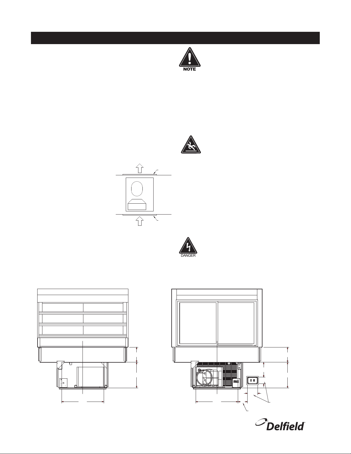
These units are installed by placing them into the counter from
above. The counter cutout sizes are as follows:
36" Units - 35.13" x 25.50" (89cm x 65cm)
48" Units - 47.13" x 25.50" (120cm x 65cm)
60" Units - 59.13" x 25.50" (150cm x 65cm)
Two louvers are provided with each
unit and must be installed in 17.00"
x 28.00" (43cm x 71cm) cutouts.
Cut-outs are to begin at 10.00"
(25cm) from the counter-top.
For the most efficient refrigeration,
be sure to provide good air
circulation inside and out. Don’t pack
the merchandiser so full that air
cannot circulate. Avoid hot corners
and locations near stoves and ovens.
Air movement in the room will adversely effect ASM refrigeration.
Do not place the model near doors or air vents.
Discharge Air
Cond.
Fresh Air In On
Customer Side
Louver
Louver
It is recommended that the unit be installed no
closer than 1” from any wall. Do not install the
unit near any combustible material or object
affected by heat or moisture.
Failure to provide the proper air flow will void the warranty.
Plumbing
Standard models will have a 1/2" drain which will need to be run
to an appropriate floor drain. The drain will be stubbed inside
the machine compartment. All units have an optional electric
condensate evaporator. If the evaporator fails, the unit’s drain
must have an outlet to an appropriate drainage area or container.
Moisture collecting from improper drainage can
create a slippery surface on the floor and a hazard
to employees. It is the owner’s responsibility to
provide a container or outlet for drainage.
Electrical connection
Refer to the amperage data on page 3, the serial tag, your
local code or the National Electrical Code to be sure the unit is
connected to the proper power source. A protected circuit of the
correct voltage and amperage must be run for con nec tion of the
line cord, or permanent connection to the unit.
An ON/OFF switch is located on the remote control panel. Simply
turn the switch to ON to begin operation. There is a second ON/
OFF switch on the remote control panel for the lights.
The power switch should be turned to OFF and
the unit disconnected from the power source
whenever performing service or maintenance
functions.
Customer Side Operator Side
C
L
28.00
Louver Cutout
4
For customer service, call (800) 733-8829, (800) 733-8821, Fax (989) 773-3210, www.deleld.com
10.00
17.00
Louver
Cutout
C
L
28.00
Louver Cutout
18" Max Distance
4.37
6.75
X
3.50" Min Distance,
18" Max Distance
10.00
Louver
17.00
Cutout
Control Cutout
Page 5
Installation, continued
ASM Series Service and Installation Manual
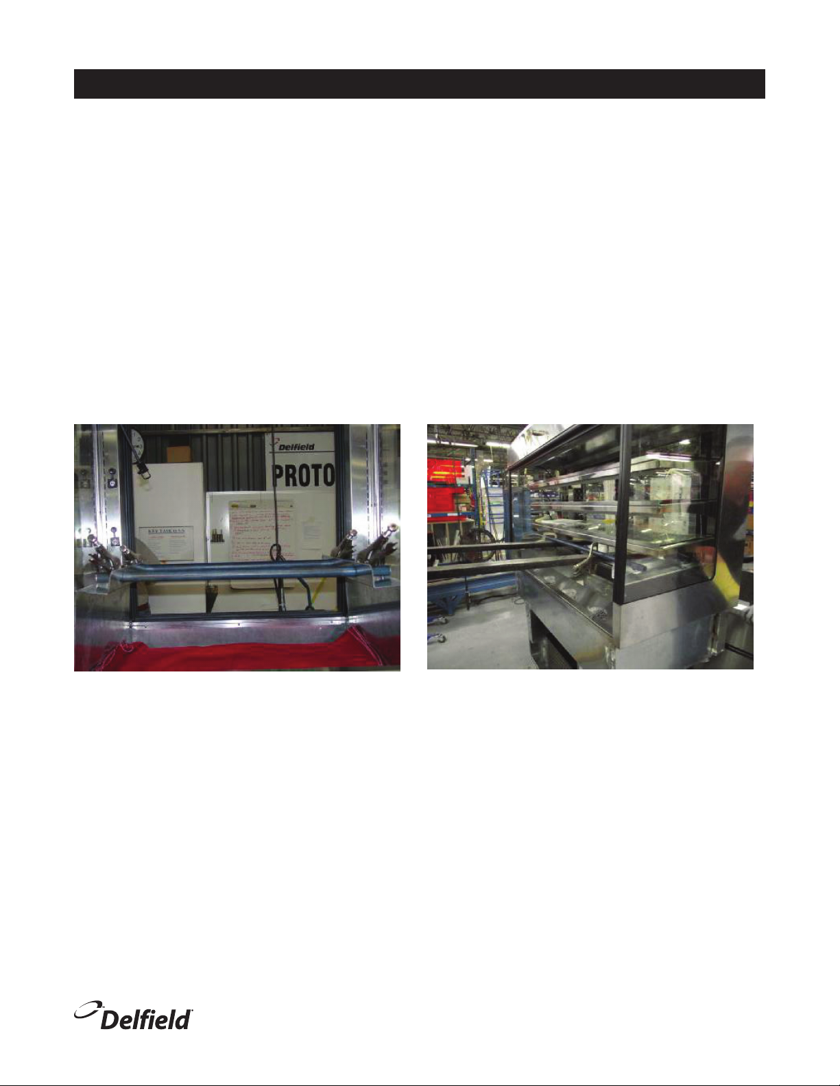
1. Remove the stainless steel pans in the bottom on the
unit.
2. Remove the stainless steel pan clip rail below the door
track.
3. Bolt in the lifting plates using the bolts (P/N 9320019)
located inside the tank that are installed in the lifting
braces.
4. Slide two 1"steel pipes into the lifting plate holes. Place
forklift forks under the pipes and clamp the forks and
pipes in position.
5. Raise the unit high enough with the forklift to roll the
base under the unit into position. Lower the ASM unit into
the base using care to clear all of the flanges and screw
heads.
6. Remove the bolts and remove the lifting plates. Install
plastic plugs (P/NRTPOOO67) in the bolt holes.
7. Install the stainless steel pan clip rail below the door
track.
8. Install the stainless steel pans in the bottom on the unit
making sure the turn down is engaged in the slot below
the door track.
9. Install the sneeze guard glass in the clips and attach the
end clip with two stainless steel self tapping screws (P/
N9321238).
10. Use gray silicone (P/N9291020) to finish the joint
between the drop in unit and the top of the base.
For customer service, call (800) 733-8829, (800) 733-8821, Fax (989) 773-3210, www.deleld.com
5
Page 6
ASM Series Service and Installation Manual
Operation
Located on the Remote Control Panel are two ON/OFF
switches. One will turn ON/OFF the unit’s com pressor. The
lights are controlled by the other switch.
Delfield's Air Screen Merchandisers are designed to maintain
an operational temperature of 36°F - 40°F (2°C - 4°C) at 80°F
(27°C) ambient room temperature in 55% or lower relative
humidity. Overloading the merchandiser, restricting the air
flow, and continuous opening and closing of the doors will
hinder the unit’s ability to maintain operational tem per a tures.
If humidity is above 55%, condensation on the glass
will be present.
Sliding Door Removal And Reinstall
Sliding Door Removal
Open the door almost completely. Firmly grasp both sides of
the door. Lift the door up and move it until it enters a notch
and can be lifted higher. Tilt the bottom out without removing
the top. Use the top to gently return the spring to the closed
position. Remove the door from the top track.
Proper airflow is critical to maintaining temperature. Do not
interfere with the airflow by placing product over the air return
openings. The Air Diffuser Pan Assembly must be properly
in place at the bottom of the merchandising case, with the
air return openings on the customer side. After cleaning or
servicing the Front Deflector Glass, Honeycomb Diffuser and
Airduct Plexiglas Panel must be replaced properly.
Sliding Door Reinstall
There is a notch in the top inside corner of the door. Put the
spring in the door's notch and move the spring to the open
position. Put the top into the track and find the notch where the
door can be lifted higher. Set bottom of the door into the track.
Night & Security Cover Operations
At the factory, the keys are taped to the display case. Pull the
cover down, turn the key 90° to lock.
6
For customer service, call (800) 733-8829, (800) 733-8821, Fax (989) 773-3210, www.deleld.com
Page 7

Shelf Adjustments
ASM Series Service and Installation Manual
Display cases come with three tempered glass shelves that are
adjustable in 1" increments.
Shelves can be slanted at three different angles. Remove the
glass and unplug the light before adjusting the shelves.
90°
96°
102°
Maximum weight for 36" shelves is 25 lbs.
Maximum weight for 48" shelves is 35 lbs.
Maximum weight for 60" shelves is 45 lbs.
Overloading shelves can damage equipment or
cause bodily injury.
Temperature Control Settings
Parameter Screen
Name
Set Point Cutout 26.1 29.66 25.1 F° Reference point, can be cut-in or cut-out based on a
Differential r01 7 4.73 8.4 F° A positive differential value gives the cut-in value,
Unit Temperature r05 1 1 1 F° C=0/F=1. Celsius or Fahrenheit readout in display
Night Setback Value r13 1.9 -7 1.9 F° Allows for a warmer or colder set point with night
Defrost Method d01 1 1 1 0=non, 1=Electric or off-cycle, 2= Hot Gas, 3=Brine
Defrost Stop Temperature d02 46.4 49.5 51.4 F° Temperature that stops defrost (defrost termination)
Interval Between Defrosts d03 3 3 3 Hours Time in between defrost
36” 48” 60” Units Parameter Description
positive or negative differential
while a negative value creates a cut-out value
curtain in down position
For customer service, call (800) 733-8829, (800) 733-8821, Fax (989) 773-3210, www.deleld.com
7
Page 8

ASM Series Service and Installation Manual
Maintenance
Drain Maintenance
Each unit has a drain located inside the unit that removes the
condensation from the evaporator coil. The drain can become
loose or disconnected during normal use. If you notice water
accumulation be sure the drain tube is connected. Be sure drain
lines are free of obstructions.
The power switch must be turned to OFF and the
unit disconnected from the power source whenever
performing service, maintenance functions or
cleaning the refrigerated area.
Plexiglas, Including Baffles
Wet a clean cloth with lukewarm water and dishwashing liquid.
Apply only light pressure, rinse with clean water and blot dry with
a damp chamois. For excessively dirty surfaces, rinse surface
dirt off before washing. Fine scratches will disappear when you
polish by hand with a plastic cleaner polish.
Never use window sprays, kitchen scouring compounds
or solvents such as acetone, gasoline, benzene,
alcohol, carbon tetrachloride or lacquer thinner to
clean plexiglas.
Stainless Steel Care and Cleaning
To prevent discoloration or rust on stainless steel, first we need
to understand the properties of stainless steel. Stainless steel
contains 70- 80% iron, which will rust. It also contains 12-30%
chromium, which forms an invisible passive film over the steel's
surface, which acts as a shield against corrosion. As long as
the protective layer is intact, the metal is still stainless. If the
film is broken or contaminated, outside elements can begin to
breakdown the steel and begin to form discoloration or rust.
Proper cleaning of stainless steel requires soft cloths or plastic
scouring pads.
Never use an acid based cleaning solution! Many
food products have an acidic content, which can
deteriorate the finish. Be sure to clean the stainless
steel surfaces of ALL food products. Common items
include, tomatoes, peppers and other vegetables.
Display Case
Do not throw items into the merchandiser. Failure to
follow this recommendation could result in damage
to the interior or blower coil. Overloading, restricting
the airflow, and continuous opening and closing of
the doors will hamper the units ability to maintain
operational temperature.
Cleaning the Condenser Coil
In order to maintain proper refrigeration performance, the
condenser fins must be cleaned of dust, dirt and grease regularly.
It is recommended that this be done at least every three months.
If conditions are such that the condenser is totally blocked in
three months, the frequency of cleaning should be increased.
Clean the condenser with a vacuum cleaner or stiff brush. If
extremely dirty, a commercially available condenser cleaner may
be required.
Failure to maintain a clean condenser coil can initially cause high
temperatures and excessive run times. Continuous operation
with a dirty or clogged condenser coil can result in compressor
failure. Neglecting the condenser coil cleaning procedures will
void any warranties associated with the compressor and cost to
replace the compressor.
Never use a high-pressure water wash for this
cleaning procedure as water can damage the electrical
components located near or at the condenser coil.
NEVER USE STEEL PADS, WIRE BRUSHES OR SCRAPERS!
Routine cleaning of stainless steel can be done with soap and
water. Extreme stains or grease should be cleaned with a nonabrasive cleaner and plastic scrub pad. Always rub with the grain
of the steel. There are stainless steel cleaners available which
can restore and preserve the finish of the steels protective layer.
Cleaning solutions need to be alkaline based or non-chloride
cleaners. Any cleaner containing chlorides will damage the
protective film of the stainless steel. Chlorides are also commonly
found in hard water, salts, and household and industrial cleaners.
If cleaners containing chlorides are used be sure to rinse
repeatedly and dry thoroughly. Early signs of stainless steel
breakdown are small pits and cracks. If this has begun, clean
thoroughly and start to apply stainless steel cleaners in attempt
to restore the passivity of the steel.
8
For customer service, call (800) 733-8829, (800) 733-8821, Fax (989) 773-3210, www.deleld.com
Sliding Doors
Frequent, regular cleaning with a mild soap and water solution
will keep the tracks free of foreign matter and will insure many
years of service. The glass may be cleaned with one of the many
commercial glass cleaners currently available.
Preventing blower coil corrosion
To help prevent corrosion of the blower coil, store all acidic
items, such as pickles and tomatoes, in sealable containers.
Immediately wipe up all spills.
Page 9

Wiring Diagrams, ASM-36 & ASM-48
ASM Series Service and Installation Manual
For customer service, call (800) 733-8829, (800) 733-8821, Fax (989) 773-3210, www.deleld.com
9
Page 10

ASM Series Service and Installation Manual
Wiring Diagrams, ASM-60
VOLTAGE (NO CONDENSATE EVAP): 208-240V-60HZ-1PH
VOLTAGE (WITH CONDENSATE EVAP): 208-240V-60HZ-1PH
CONDENSATE
EVAPORATOR
OPTION
L2
L1
N G
S1
NOSING HEATER WIRE
#1 #2
DANFOSS
EKC 204A
CONTROL
#8
#4
#9
COND UNIT RELAY
#5
HIGH PRES
SWITCH
#0 #1
#2 #4
#6 #8
EVAPORATOR FANS
CONDENSING UNIT (220V)
S1
S2
BALLAST
FLUORESCENT LIGHTS
10
For customer service, call (800) 733-8829, (800) 733-8821, Fax (989) 773-3210, www.deleld.com
Page 11

ASM Series Service and Installation Manual
Wiring Diagrams, Remote Models, ASM-36R, ASM-48R, ASM-60R
For customer service, call (800) 733-8829, (800) 733-8821, Fax (989) 773-3210, www.deleld.com
11
Page 12

ASM Series Service and Installation Manual
ASM-36 Condensing Unit Assembly 1/2 H.P.
Key Delfield Part # Description
- 000-BN5-0035 Condensing Unit Assembly
1 026-C58-0031 Shroud, 1/2 HP condenser coil
2 3516554 Blade, fan 9.00”, 5 pedal
3 2160019 Guard, fan, condenser, upright
4 2162716 Motor, fan, 16W, 115V
5 3516462 Capacitor, start, assembly
6 3527026 Compressor, SC12MLX, 115V/60Hz, Danfoss
7 3516331 High pressure switch
8 3516322 Filter dryer, (2) inlet, .25”
9 3516459 Tank, receiver
10 075-231-0031 Pan, condensate
11 3516455 Coil, 1/2 HP condensing
2
1
4
3
6
5
7
8
9
11
ASM-48 Condensing Unit Assembly 3/4 H.P.
4
3
2
1
6
7
Key Delfield Part # Description
- 000-BN5-0036 Condensing Unit Assembly
1 026-C58-0032 Shroud, 3/4 HP condenser coil
2 2160019 Guard, fan, condenser, upright
3 3516442 Capacitor, start, run, assembly
4 3527021 Compressor, SC18MLX, 115V/60Hz, Danfoss
5 3516322 Filter dryer, (2) inlet, .25”
5
6 3516360 Tank, receiver
7 3516456 Coil, condenser, 3/4 HP
- 075-231-0031 Pan, condensate
- 3516433 Blade, fan 25º, 10”, CW, upright
- 2162716 Motor, fan, 16W, 115V
10
12
For customer service, call (800) 733-8829, (800) 733-8821, Fax (989) 773-3210, www.deleld.com
Page 13

ASM-60 Condensing Unit Assembly 1 H.P.
Key Delfield Part # Description
- 000-254-0005 Condensing Unit Assembly
1 3527008 Condensing Unit, 1HP
3
2
1
2 3516322 Filter dryer, (2) inlet, .25”
3 3516331 Switch, Hi Pressure
ASM Series Service and Installation Manual
Replacement Parts
Part # Description
2184182 Black Female Light Socket
3239598 Condensate Evap,120V
3239669 Condensate Evap,208V
2195303 Control
3516101 Filter Dryer
3516247 High Pressure Control
2194755 Probe, 60” Lg
2194809 Probe, 118” Lg
2195088 Relay
2190154 Rocker Switch, Single
tbp60137 Rocker Switch, Double
For customer service, call (800) 733-8829, (800) 733-8821, Fax (989) 773-3210, www.deleld.com
13
Page 14

ASM Series Service and Installation Manual
Replacement Parts, continued
2
4
3rd Fan Assy Required
On ASM-60 Only
7
8
9
7
8
9
6
6
6
5
1
3
3
10
11
9
4
12
1314
15
16
Key ASM-36 Part # ASM-48 Part # ASM-60 Part # Description
1 3239663 3239662 3239661 Sliding Door Set
2 263-b4g-0041 263-b4g-0041 263-b4g-0041 3" Plexi Airduct Bracket
3 263-b4g-0040 263-b4g-0040 263-b4g-0040 3.75" Plexi Airduct Bracket
4 103-246-0043 103-246-0044 103-246-0045 Plexi Airduct Panel
5 019-0v1-0040 019-0v1-0041 019-0v1-0042 Fan Cover
6 3516173 3516173 3516173 Evaporator Fan Guard
7 3516172 3516172 3516172 CCW Clear Evaporator Fan Blade
8 2162691 2162691 2162691 CW Evaporator Fan Motor
9 031-264-0000 031-264-0000 031-264-0000 Evaporator Fan Motor Bracket
10 3517356 3517356 3517356 CW Black Evaporator Fan Blade
11 2162693 2162693 2162693 CCW Evaporator Fan Motor
12 327-b0v-0037 327-b0v-0036 327-b0v-0035 Sliding Door Track
13 3517374 3517375 3517376 Evaporator Coil
14 3517379 3517379 3517380 Expansion Valve, R404A
15 2195300 2195300 2195300 Ballast
16 000-bn5-0035 000-bn5-0036 000-254-0005 Condensing Unit Assembly
14
For customer service, call (800) 733-8829, (800) 733-8821, Fax (989) 773-3210, www.deleld.com
Page 15

Replacement Parts, continued
1
2 3
ASM Series Service and Installation Manual
14
12
13
11
10
9
8
4
5
6
7
Key ASM-36 Part # ASM-48 Part # ASM-60 Part # Description
1 3239673 3239673 3239673 Door Lock
2 3235065 3235065 3235065 Security Cover Lifting Mech,
3 2195304 2195304 2195304 Roller Lever Switch
4 3235062 3235063 3235064 Cover Assembly, Includes Handles & Lifting Mech.
3235068 3235068 3235068 Security Cover Slat
5 2194947 2194948 2194949 Fluorescent Light Fixture
6 1706117 1706117 1706117 Honeycomb Diffuser
7 2186849 2186850 2186851 Heater Wire
8 000-bx4-0040 000-bx4-0041 000-bx4-0042 Air Diffuser Pan Assembly
9 359-411-000k 359-411-000k 359-411-000k Front Louvered Panel
10 3455639 3455640 3455641 Front Glass Deflector
11 2194947 2194948 2194949 Fluorescent Light Fixture
12 000-bx5-0030 000-bx5-0031 000-bx5-0032 Shelf Assembly
13 3455644 3455643 3455642 Shelf Glass
14 3235066 3235066 3235066 Security Cover Handle
3235067 3235067 3235067 Recessed Handle Pocket
3235069 3235069 3235069 Recessed Handle End Cap
For customer service, call (800) 733-8829, (800) 733-8821, Fax (989) 773-3210, www.deleld.com
15
Page 16

ASM Series Service and Installation Manual
Standard Labor Guidelines To Repair Or Replace Parts On Delfield Equipment
Advice and recommendations given by Delfield Service Technicians do not constitute or guarantee any special coverage.
•Amaximumof1-hourisallowedtodiagnose a defective component.
•Amaximumof1-hourisallowedforretrieval of parts not in stock.
•Amaximumtravel distance of 100 miles round trip and 2-hours will be reimbursed.
•Overtime,installation/start-up,normalcontroladjustments,generalmaintenance,glassbreakage,freightdamage,and/or
correcting and end-user installation error will not be reimbursed under warranty unless pre-approved with a Service Work
Authorization from Delfield. You must submit the number with the service claim.
Labor Of 1-Hour Is Allowed To Replace:
•Ballast/Light
•CirculatingFanMotorandBlade
•CompressorStartComponentsandOverloadProtector
•DoorHinges,Locks,andGaskets
•Evaporator/CondenserFanMotorandBlade
•MicroprocessorControl
Labor Of 2 Hours To Replace:
•Locate/RepairLeak
Labor Of 3 Hours To Replace:
•CondenserorEvaporatorCoil
•ExpansionValve
Labor Of 4 Hours To Replace:
•Compressor
This includes recovery of refrigerant and leak check.
$55.00 maximum reimbursement for refrigerant recovery (includes recovery machine, pump, torch, oil, flux, minor fittings,
solder, brazing rod, nitrogen, or similar fees.)
Refrigerants:
•R404AAmaximumof$15.00/lb.or$1.00/oz.willbereimbursed.
16
For customer service, call (800) 733-8829, (800) 733-8821, Fax (989) 773-3210, www.deleld.com
Page 17

ASM Series Service and Installation Manual
Standard One Year Limited Warranty (One year parts and labor)
The Deleld Company (“Deleld”) warrants to the Original Purchaser
of the Deleld product (herein called the “Unit”) that such Unit, and all
parts thereof, will be free from defects in material and workmanship
under normal use and service for a period of one (1) year from the
date of shipment of the Unit to the Original Purchaser or, if the
Original Purchaser returns the warranty card completely lled out
including the date of installation within thirty (30) days of receipt
of the Unit, one (1) year from the date of installation. During this
one year warranty period, Deleld will repair or replace any defective
part or portion there of returned to Deleld by the Original Purchaser
which Deleld determines was defective due to faulty material or
workmanship. The Original purchaser will pay all labor, crating, freight
and related costs incurred in the removal of the Unit or defective
component and shipment to Deleld, except that during a period of
either ninety (90) days from the date of shipment of the Unit to the
Original Purchaser or, if the Original Purchaser returns the warranty
card completely lled out including the date of installation within thirty
(30) days of receipt of the Unit, ninety (90) days from the date of
installation Deleld will pay all related labor costs. Deleld will pay the
return costs if the Unit or part thereof was defective.
The term “Original Purchaser” as used herein means that person, rm,
association, or corporation for whom the Unit was originally installed.
This warranty does not apply to any Unit or part thereof that has
been subjected to misuse, neglect, alteration, or accident, such as
accidental damage to the exterior nish, operated contrary to the
recommendations specied by Deleld; or repaired or altered by anyone
other than Deleld in any way so as to, in Deleld’s sole judgement,
affect its quality or efficiency. This warranty does not apply to any Unit
that has been moved from the location where it was originally installed.
This warranty also does not cover the refrigerator drier or the light
bulbs used in the Unit. The warranty is subject to the user’s normal
maintenance and care responsibility as set forth in the Service
and Installation Manual, such as cleaning the condenser coil,
and is in lieu of all other obligations of Deleld. Deleld neither
assumes, nor authorizes any other person to assume for Deleld,
any other liability in connection with Deleld’s products.
Removal or defacement of the original Serial Number or Model Number
from any Unit shall be deemed to release Deleld from all obligations
hereunder or any other obligations, express or implied.
Parts furnished by suppliers to Deleld are guaranteed by Deleld only
to the extent of the original manufacturer’s express warranty to Deleld.
Failure of the Original Purchaser to receive such manufacturers
warranty shall in no way create any warranty, expressed or implied,
or any other obligation or liability on Deleld’s part in respect thereof.
IF THE CUSTOMER IS USING A PART THAT RESULTS IN A VOIDED
WARRANTY AND A DELFIELD AUTHORIZED REPRESENTATIVE
TRAVELS TO THE INSTALLATION ADDRESS TO PERFORM
WARRANTY SERVICE, THE SERVICE REPRESENTATIVE WILL
ADVISE CUSTOMER THE WARRANTY IS VOID. SUCH SERVICE
CALLS WILL BE BILLED TO CUSTOMER AT THE AUTHORIZED
SERVICE CENTER’S THEN APPLICABLE TIME AND MATERIALS
RATES. CONSIDER: CUSTOMER MAY INITIATE A SERVICE
AGREEMENT WITHOUT PARTS COVERAGE.
If shipment of a replacement part is requested prior to the arrival in
the Deleld factory of the part claimed to be defective, the Original
Purchaser must accept delivery of the replacement part on a C.O.D.
basis, with credit being issued after the part has been received and
inspected at Deleld’s plant and determined by Deleld to be within
this warranty.
Under no condition does this warranty give the Original Purchaser the
right to replace the defective Unit with a complete Unit of the same
manufacturer or of another make. Unless authorized by Deleld in
writing, this warranty does not permit the replacement of any part,
including the motor-compressor, to be made with the part of another
make or manufacturer.
No claims can be made under this warranty for spoilage of any
products for any reason, including system failure.
The installation contractor shall be responsible for building access,
entrance and eld conditions to insure sufficient clearance to allow any
hood(s), vent(s), or Unit(s) if necessary, to be brought into the building.
Deleld will not be responsible for structural changes or damages
incurred during installation of the Unit or any exhaust system.
Deleld shall not be liable in any manner for any default or delay in
performance hereunder caused by or resulting from any contingency
beyond Deleld’s control, including, but not limited to, war, governmental
restrictions or restraints, strike, lockouts, injunctions, re, ood, acts of
nature, short or reduced supply of raw materials, or discontinuance of
the parts by the original part manufacturer.
Except as provided in any Additional Four Year Protection Plan,
if applicable, and the Service Labor Contract, if applicable, the
foregoing is exclusive and in lieu of all other warranties, whether
written or oral, express or implied. This warranty supersedes
and excludes any prior oral or written representations or
warranties. Deleld expressly disclaims any implied warranties
of merchantability, tness for a particular purpose, or compliance
with any law, treaty, rule or regulation relating to the discharge
of substances into the environment. The sole and exclusive
remedies of any person relating to the Unit, and the full liability
of Deleld for any breach of this warranty, will be as provided in
this warranty.
Other than this Deleld Standard One Year Limited Warranty, any
applicable Deleld Additional Four Year Protection Plan or applicable
Deleld Service Labor Contract, the Original Purchaser agrees and
acknowledges that no other warranties are offered or provided in
connection with or for the Unit or any other part thereof.
In no event will Deleld be liable for special, incidental or consequential
damages, or for damages in the nature of penalties.
IF DURING THE WARRANTY PERIOD, CUSTOMER USES A PART
FOR THIS DELFIELD EQUIPMENT OTHER THAN AN UNMODIFIED
NEW OR RECYCLED PART PURCHASED DIRECTLY FROM
DELFIELD OR ANY OF ITS AUTHORIZED SERVICE CENTERS
AND/OR THE PART BEING USED IS MODIFIED FROM ITS
ORIGINAL CONFIGURATION, THIS WARRANTY WILL BE VOID.
FURTHER, DELFIELD AND ITS AFFILIATES WILL NOT BE LIABLE
FOR ANY CLAIMS DAMAGES OR EXPENSES INCURRED BY THE
CUSTOMER WHICH ARISE DIRECTLY OR INDIRECTLY, IN WHOLE
OR IN PART, DUE TO THE INSTALLATION OF ANY MODIFIED PART
AND/OR PART RECEIVED FROM AN UNAUTHORIZED SERVICE
CENTER. If the warranty becomes void, Customer may purchase
from Deleld, if available, a Service Agreement or service at the
then current time and materials rate.
For more information on Deleld warranty’s log on and check out the
service section of our web site at www.deleld.com.
For customer service, call (800) 733-8829, (800) 733-8821, Fax (989) 773-3210, www.deleld.com
17
Page 18

ASM Series Service and Installation Manual
Additional Four Year Protection Plan (For Motor-Compressor Only)
Installation
Delfield Model# Serial # Date
In addition to the Standard One Year Warranty on the Motor-Compressor
contained in the above listed Delfield product (the “Unit”), The Delfield
Company (“Delfield”) also agrees to repair, or exchange with similar or
interchangeable parts in design and capacity at Delfield’s option, the defective
Motor-Compressor contained in the Unit (the “Motor-Compressor), or any part
thereof, for the Original Purchaser only, at any time during the four (4) years
following the initial one (1) year period commencing on the date of installation
for the Original Purchaser. Failure of the Original Purchaser to register the
registration card containing the Original Purchasers name, address, date
of installation, model number and serial number of the Unit containing the
Motor-Compressor within 30 days from the date of installation shall void this
warranty. This additional warranty is only available if the Motor-Compressor is
inoperative due to defects in material or factory workmanship, as determined
by Delfield in its sole judgement and discretion. The Original Purchaser shall
be responsible for returning the defective Motor-Compressor to Delfield
prepaid, F.O.B. at the address shown on the back cover of this manual.
The term “Original Purchaser” as used herein means that person, firm,
association, or corporation for whom the Unit was originally installed.
The term “Motor-Compressor” as used herein does not include unit base,
air or water cooled condenser, receiver, electrical accessories such as relay,
capacitors, refrigerant controls, or condenser fan/motor assembly. This
warranty does not cover labor charges incidental to the replacement of
parts. This warranty further does not include any equipment to which said
condensing unit is connected, such as cooling coils, temperature controls
or refrigerant metering devices. This warranty shall be void if the MotorCompressor, in Delfield’s sole judgement, has been subjected to misuse,
neglect, alteration or accident, operated contrary to the recommendations
specified by the Unit manufacturer, repaired or altered by anyone other than
Delfield in any way so as, in Delfield’s sole judgment, to affect its quality or
efficiency or if the serial number has been altered, defaced or removed. This
Warranty does not apply to a Motor-Compressor in any Unit that has been
moved from the location where it was originally installed. The addition of
methyl chloride to the condensing unit or refrigeration system shall void this
warranty.
General Conditions
Delfield shall not be liable in any manner for any default or delay in
performance hereunder caused by or resulting from any contingency beyond
Delfield’s control, including, but not limited to, war, governmental restrictions
or restraints, strike, lockouts, injunctions, fire, flood, acts of nature, short or
reduced supply of raw materials, or discontinuance of any part or the MotorCompressor by the unit manufacturer.
the right to purchase a complete replacement Motor-Compressor of the
same make or of another make. It further does not permit the replacement
to be made with a Motor-Compressor of another kind unless authorized by
Delfield. In the event Delfield authorizes the Original Purchaser to purchase a
replacement Motor-Compressor locally, only the wholesale cost of the MotorCompressor is refundable.
Expressly excluded from this warranty are damages resulting from spoilage of
goods.
Except as provided in any applicable Standard One Year Limited Warranty
or applicable Service Labor Contract, the foregoing is exclusive and in lieu
of all other warranties, whether written or oral, express or implied. This
Warranty supersedes and excludes any prior oral or written representations
or warranties. Delfield expressly disclaims any implied warranties of
merchantability, fitness for a particular purpose or compliance with any law,
treaty, rule or regulation relating to the Motor-Compressor, and the full liability
of Delfield for any breach of this warranty, will be as provided in this warranty.
Other than any applicable Delfield Standard One year Limited Warranty, this
Delfield Additional Four Year Protection Plan and any applicable Delfield
Service Labor Contract, the Original Purchaser agrees and acknowledges
that no other warranties are offered or provided in connection with or for the
Motor-Compressor or any part thereof.
In no event will Delfield be liable for special, incidental or consequential
damages, or for damages in the nature of penalties.
Replacement of a defective Motor-Compressor is limited to one (1) MotorCompressor by us during the four (4) year period. Delfield shall replace the
Motor-Compressor at no charge.
This warranty does not give the Original Purchaser of the Motor-Compressor
18
For customer service, call (800) 733-8829, (800) 733-8821, Fax (989) 773-3210, www.deleld.com
Page 19

Notes
ASM Series Service and Installation Manual
For customer service, call (800) 733-8829, (800) 733-8821, Fax (989) 773-3210, www.deleld.com
19
Page 20

Mt. Pleasant, MI Covington, TN
Thank you for choosing Delfield!
Help is a phone call away. Help our team of professional, courteous
customer service reps by having your model number and serial number
available at the time of your call (800) 733-8829
Model: ________________________S/N: ______________________
Installation Date: _______________________
For a list of Delfield’s authorized parts depots,
visit our website at www.delfield.com
980 S. Isabella Rd., Mt. Pleasant, MI 48858, U.S.A. • (989) 773-7981 or (800) 733-8829 • Fax (989) 773-3210 • www.deleld.com
Deleld reserves the right to make changes in design or specications without prior notice. ©2011 The Deleld Company. All rights reserved. Printed in the U.S.A.
DMASM 08/11
 Loading...