

Page 1
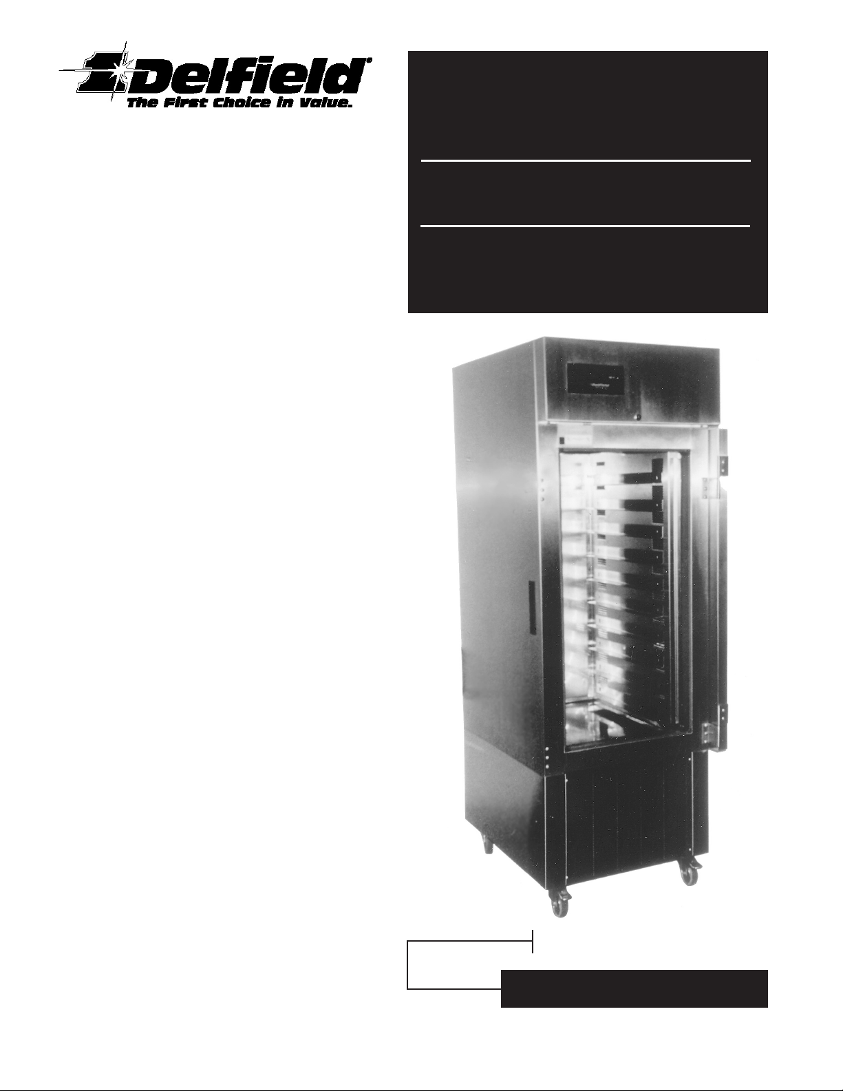
Service and
Installation Manual
Please read this manual completely before attempting to install
or operate this equipment! Notify carrier of damage! Inspect all
components immediately. See page 2.
Air Curtain Refrigerator
ACR-26S
Effective September 1998
Page 2

074-2900
DELFIELD
PART NUMBER
MODEL
NUMBER
H.P.AMPS
VOLTS/HERTZ/
PHASE
STORAGE
CAPACITY
18" x 26" TRAY
CAPACITY
BTU/HR
DOOR CLOSED
BTU/HR
SYSTEM CAP.
Air Curtain Refrigerator
ACR-26S
1/2 504 3300 5-15P
SHIP
WEIGHT
NEMA
PLUG
592 lbs./266 kg.1012.0 12.5 ft
3
115V/60Hz/1ph
Contents
Serial Number Information
SERIAL NUMBER LOCATION . . . . . . . . . . . . . . . . . . . . . .2
RECEIVING AND INSPECTING . . . . . . . . . . . . . . . . . . . .2
MECHANICAL DATA . . . . . . . . . . . . . . . . . . . . . . . . . . . .2
INSTALLATION . . . . . . . . . . . . . . . . . . . . . . . . . . . . . . . . .3
MAINTENANCE . . . . . . . . . . . . . . . . . . . . . . . . . . . . . . . .4
MCII Tempatrol® FUNCTION SETTINGS . . . . . . . . . . . . .4
BASIC OPERATION. . . . . . . . . . . . . . . . . . . . . . . . . . . . . .5
MCII TEMPATROL®
Controls . . . . . . . . . . . . . . . . . . . . . . . . . . . . . . . . . . . . .5
Display functions . . . . . . . . . . . . . . . . . . . . . . . . . . . . . .5
Programming . . . . . . . . . . . . . . . . . . . . . . . . . . . . . . . . .6
Defrost settings. . . . . . . . . . . . . . . . . . . . . . . . . . . . . . . .8
Optional settings. . . . . . . . . . . . . . . . . . . . . . . . . . . . . . .8
Self-diagnostic system . . . . . . . . . . . . . . . . . . . . . . . . . .10
REFERENCE CHARTS
MCII Tempatrol® CHECK SYSTEM warnings . . . . . . .10
MCII Tempatrol® diagnostic codes. . . . . . . . . . . . . . . .11
MCII Tempatrol® display . . . . . . . . . . . . . . . . . . . . . . .11
MCII Tempatrol® troubleshooting . . . . . . . . . . . . . . . .12
WIRING DIAGRAM. . . . . . . . . . . . . . . . . . . . . . . . . . . . .13
REPLACEMENT PARTS LISTS . . . . . . . . . . . . . . . . . . . . .14
WARRANTIES . . . . . . . . . . . . . . . . . . . . . . . . . . . . . . 16-17
AUTHORIZED PARTS DEPOTS . . . . . . . . . . . . . back cover
To view the serial number of the ACR-26S refrigerator, open
the door of the unit. The serial number is located on the inside
back wall in the top left corner of the unit.
Always have the serial number of your unit available when call
ing for parts or service. A complete list of authorized Delfield
parts depots is shown on the back cover of this manual.
©1998 The Delfield Company. All rights reserved. Reproduction without
written permission is prohibited.
The starburst “1” symbol is a trademark and “Delfield” is a registered
trademark of The Delfield Company.
-
Receiving and Inspecting the Equipment
Even though most equipment is shipped crated, care should
be taken during unloading so the equipment is not damaged
while being moved into the building.
Carefully check for any visable signs of damage to cartons or
containers. If evidence of damage exists, the package should
be opened immediately and joint inventory and examination
of the contents should be made by you and the driver.
Concealed damage
If a concealed loss or damage is discovered after you have
given the carrier a clear delivery receipt, notify the carrier
in writing immediately or within 10 days from the
delivery date. If you phone the carrier, you must follow
up the call in writing to protect your rights. You can only
improve your position as a claimant by promptly reporting
such loss or damage. You should also retain all cartons or
containers, including packing material, until an inspection has been made or waived.
Filing a claim
Notation of loss or damage does not constitute the filing of a
claim. You should file your claim in writing with the carrier
immediately!
Carriers will furnish the necessary form upon request. You
should also request an inspection. If a claim is filed by
phone, always follow up immediately in writing.
Specifications
2
For customer service, call (800) 733-8829,
(800) 733-8821 or (517) 773-7981
Page 3

Installation
When the door is open, Delfield’s patented air curtain design
directs cold air across the cabinet opening, keeping hot air
out and cold air in for extended periods of time. The unit
will maintain a maximum of 45°F box temperature at 70°F
ambient with the door open during peak production times,
quickly returning to a normal 36°F. With the door closed,
a maximum 40°F at 100°F ambient is maintained (normal
operation) while running only 15% in an 85° room.
Location
Be sure the location chosen has a floor strong enough to support the total weight of the cabinet and contents. Reinforce
the floor if necessary to provide for maximum loading.
Don’t pack the interior of the refrigerator so full that air cannot circulate. When operating open, keep trays pushed all the
way in so that they do not disrupt the air curtain air flow.
Avoid placing unit under air conditioning vents or other ventilation fans that may affect the air curtain when door is open.
Leveling
A level cabinet looks better and will perform better because the
doors will line up with the door frames properly, the cabinet
will not be subject to undue strain, and the contents of the cabinet will not move around on the shelves. Use a level to make
sure the unit is level from front to back and side to side.
Stabilizing
The ACR-26S is supplied with casters for your convenience,
ease of cleaning underneath and for mobility. Two locking
casters allow you to stabilize the unit if you are loading or
unloading product.
Electrical connection
Refer to the amperage data shown on page 1 of this manual,
the serial tag and your local code or the National Electrical
Code for proper wire sizes. All case wiring is labeled with
the required voltage-be sure it is connected to the proper
power source. A protected circuit of the correct voltage and
amperage must be run for connection of the line cord or permanent connection to the unit.
The power switch should be turned to the OFF position and
the power cord disconnected whenever performing maintenance functions or cleaning the refrigerated cabinet area.
Reversing the door hinging
The following steps will allow you to reverse the side the
door hinges on.
1. Open the door to 180° open position.
2. Lift up door and remove door from hinges in fully open
position.
3. Remove pins from hinges.
4. Remove both hinges and relocate on the opposite side.
Tighten hinges.
5. Unscrew the lock stop tab from the top of door and
mount to the bottom in the holes provided.
6. Invert the door and mount it into the hinges in the
fully open position.
Magnetic door
Open the ACR’s door completely and the magnetic strip built
in to the frame allows the door to remain open while loading
or unloading.
Maintenance
The interior and exterior can be cleaned using soap and
warm water. If this is not sufficient, try ammonia and water
or a nonabrasive liquid cleaner. When cleaning the exterior,
always run with the “grain” of the stainless steel to avoid
marring the finish. Do not use an abrasive cleaner because it
will scratch the stainless steel and plastic.
In order to maintain proper refrigeration performance, the
condenser fins must be cleaned of dust, dirt and grease
regularly. It is recommended that this be done at least every
three months. If conditions are such that the condenser is
totally blocked in three months, the frequency of cleaning
should be increased. Clean the condenser with a vacuum
cleaner or stiff brush. If extremely dirty, a commercially
available condenser cleaner may be required.
Door gaskets should be cleaned as required to maintain their
ability to seal properly. Do not use sharp tools or knives to
scrape the bellows as this may tear the gasket and eliminate its
ability to seal. A bristle brush and solution of soap and water
should be all this is required to keep the gaskets clean. Do not
use full strength de-greasing agents on the gasket because they
could cause the gasket to crack and become brittle.
Customer service FAX (517) 773-3210
3
Page 4

MCII Function Settings
The MCII microprocessor has been preset at the factory for the following functions eliminating the need for
programming when your unit arrives. These settings
must be correct for your unit to operate properly.
1. Enter diagnostic . . . . . . . . . . Press down + time > temp
2. Enter Phase II . . . . . . . . . . . . . . . . . . . . . . . Press defrost
3. Scroll to “Basic function” . . . . . . Press up/down - go to
“012”**** - set at 0:01
4. Scroll to temperature range . . . . . . Press up/down - go to
“015” - set at 0:07
5. Scroll to defrost termination temp . . . . . Press up/down
-go to “005” - set at 0.03
6. Press reset button
7. Press temp button. . . . . . . . . . . . . Temp should read 0°F
8. Scroll up or down . . . . . . . . . . . . . . . . Set at 36°F (2°C)
***Basic function (“012”) must be set first otherwise
it will cancel out everything previously entered.
Basic Operation -
After plugging the unit in and turning the power switch to
ON, the unit will operate immediately upon start without
any programming of the MCII Tempatrol
freezer temperature is preset to 0°F and the refrigerator is
preset to 37°F. NOTE: Freezer cabinets have a built-in differ
ential; the actual interior temperature will be 0 to 3 degrees
lower than the set point.
When the unit is started, the digital display will flash, and will
continue flashing if the interior cabinet temperature is over the
set temperature range. When the cabinet is cooled to the set
For Units Built With The MCII Tempatrol
®
required. The
®
temperature range, the display will stop flashing.
When the unit is restarted after a power interruption, the digital display will flash only if the interior cabinet temperature is
over the set temperature range. When the cabinet is cooled to
-
the set temperature range, the display will stop flashing.
Every time the unit is started or restarted, the clock must be set
to the correct time of day if a custom defrost plan has been previously entered into the MCII Tempatrol. Otherwise, the clock
will resume at the time when the power was interrupted.
4
For customer service, call (800) 733-8829,
(800) 733-8821 or (517) 773-7981
Page 5
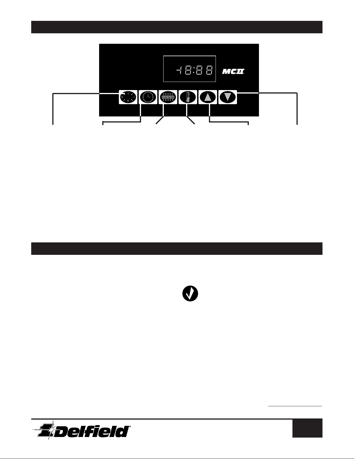
MCII Tempatrol
RESET
®
CHECK SYSTEM DEFROST
AM PM
CLEAN
CONDENSER
DOOR AJAR
ST PE SST PE S
®
Controls
RESET
• Turns off alarms
• Terminates the cur-
rent defrost cycle
• Returns display of
cabinet temperature
MCII Tempatrol
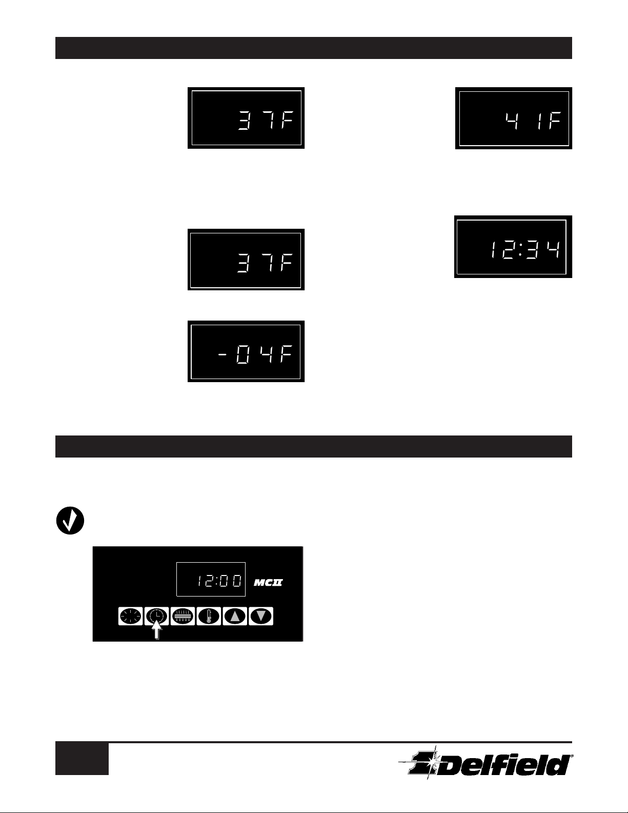
Normal display
Normal display
The normal display is the interior cabinet temperature in
The normal display is the interior cabinet temperature in
degrees Fahrenheit. (For details on changing the display
degrees Fahrenheit. (For details on changing the display
to show the temperature in degrees Celsius, see page 10.)
to show the temperature in degrees Celsius, see page 10.)
Pressing the RESET button always displays current temper-
Pressing the RESET button always displays current temperature. By pressing TEMP, you can read the set point of the
ature. By pressing TEMP, you can read the set point of the
interior cabinet. The display will automatically return to the
interior cabinet. The display will automatically return to the
current interior temperature after one minute.
current interior temperature after one minute.
It is not unusual for the interior temperature to rise rapidly
It is not unusual for the interior temperature to rise rapidly
when a door is opened. The temperature displayed is usu-
when a door is opened. The temperature displayed is usually the warmest temperature inside the unit. This is done
ally the warmest temperature inside the unit. This is done
purposely to make sure that the entire storage area is always
purposely to make sure that the entire storage area is always
represented by the display and assures that the refrigeration
represented by the display and assures that the refrigeration
system is activated quickly to return the storage area to its
system is activated quickly to return the storage area to its
correct temperature.
correct temperature.
Remember that the temperature displayed represents a pre-
Remember that the temperature displayed represents a precision measurement of the actual air temperature, not an
cision measurement of the actual air temperature, not an
average temperature. When a door is opened, the cold air
average temperature. When a door is opened, the cold air
literally “falls out” and warm air rushes in. What the display
literally “falls out” and warm air rushes in. What the display
shows is real, and provides more accurate control.
shows is real, and provides more accurate control.
TIME
• Displays the current
time (if set)
• Allows setting the
clock by pressing UP
and DOWN buttons
• Starts a manual
defrost cycle when
pressed simultaneously with
DEFROST
®
Display Functions
DEFROST
• Displays current
defrost setting
(A,3,4,6 or 8)
• Allows setting
defrost setting and
times by pressing
UP and DOWN but
tons
• Starts a manual
defrost cycle when
pressed simultaneously with TIME
TEMP
• Displays current temperature set point
• Allows modification
of set point by press
ing UP and DOWN
buttons
-
Normal display
Flashing temperature disply
The normal display is the interior cabinet temperature in
A flashing temperature display can be caused by four situadegrees Fahrenheit. (For details on changing the display to
tions, and is the first signal of a possible problem:
show the temperature in degrees Celsius, see page
1. The unit has been started, or restarted after a
10.) Pressing the RESET button always displays cur-
power loss, and has not yet reached set tempera-
rent temperature. By pressing TEMP, you can read
ture.
the set point of the interior cabinet. The display will
2. The interior cabinet is over temperature. This
automatically return to the current interior tempera-
occurs when a freezer reaches 32°F (0°C) or
ture after one minute.
when a refrigerator reaches 65°F (18°C). This
It is not unusual for the interior temperature to rise
condition will stop when the temperature returns
rapidly when a door is opened. The temperature
to a reading below these warning levels.
displayed is usually the warmest temperature inside
3. Long duty cycle. The unit has been running
the unit. This is done purposely to make sure that
for one continuous hour without a door being
the entire storage area is always represented by the
opened. This condition will stop if RESET is
display and assures that the refrigeration system is
pressed, a door is opened, or if the compressor
activated quickly to return the storage area to its cor-
shuts off.
rect temperature.
4. The door has been ajar for over one minute. This
Remember that the temperature displayed represents
condition will stop if the door is closed.
a precision measurement of the actual air tempera-
ture, not an average temperature. When a door is
opened, the cold air literally “falls out” and warm air
• When time is
• When defrost set
-
• When first defrost
• When set point is
UP
displayed, changes
time forward
ting is displayed,
moves forward
through choices
time is displayed,
moves the hour
forward
displayed, moves set
point up one degree
Continued on the next page
• When time is
displayed, changes
time backward
• When defrost set
ting is displayed,
moves backward
through choices
• When first defrost
time is displayed,
moves the hour
backward
• When set point is
displayed, moves
set point down one
degree
DOWN
-
Customer service FAX (517) 773-3210
5
Page 6
MCII Tempatrol
®
CHECK SYSTEM DEFROST
AM PM
CLEAN
CONDENSER
DOOR AJAR
®
CHECK SYSTEM DEFROST
AM PM
CLEAN
CONDENSER
DOOR AJAR
®
CHECK SYSTEM DEFROST
AM PM
CLEAN
CONDENSER
DOOR AJAR
®
CHECK SYSTEM DEFROST
AM PM
CLEAN
CONDENSER
DOOR AJAR
®
CHECK SYSTEM DEFROST
AM PM
CLEAN
CONDENSER
DOOR AJAR
ST PE S
RESET
®
CHECK SYSTEM DEFROST
AM PM
CLEAN
CONDENSER
DOOR AJAR
®
Display Functions
(continued)
Door ajar
The DOOR AJAR indicator
light will come on when a
door is opened. If the door
remains open for more than
one minute, the temperature
display will begin to flash.
After three minutes, a loud beep is emitted every three seconds. The flashing display and warning beep will stop when
RESET is pressed. If the door is not closed when RESET is
pressed, the same cycle will repeat.
Clean condenser
The CLEAN CONDENSER
indicator light is a maintenance reminder that comes
on every 90 days. It will go
off when the RESET button is
pressed.
Defrost
The DEFROST indicator light
comes on during defrosting
cycles. The defrost cycle may
be terminated by pressing the
RESET button. Warmer interior cabinet temperatures are
normal during and after defrosting.
Check system
The CHECK SYSTEM indicator light comes on when a
significant malfunction of the
unit has occurred, such as an
incomplete defrost, continuous compressor operation with
accompanying over-temperature
condition, or sensor failure. After 2™ hours in this condition, a
loud warning beep is emitted every second. The beep will stop
if RESET is pressed.
Clock display
Setting the CLOCK is not
essential to operation unless
custom defrost times have
been set on freezer units and
while not in automatic (A)
mode. If the power is interrupted, the clock may have to be
reset for correct custom defrost timing.
Setting the clock
To set the clock, perform the following steps:
®
MCII Tempatrol
Programming
1) Press RESET to clear the flashing display; this
must be done to make the rest of the keypad
functional.
2) Press the TIME button to show current time (set
to 12:00 a.m. when started or restarted).
6
For customer service, call (800) 733-8829,
(800) 733-8821 or (517) 773-7981
3) Press UP or DOWN to set the correct time.
Note the AM and PM indicators at the left of the
clock display.
4) Press
RESET to return to interior cabinet tem-
perature display.
If the defrost cycle starts while the clock is being set, stop
pressing the UP or DOWN button and wait a couple of
seconds before continuing. This will help to keep the time
display advancing quickly.
Page 7

®
RESET
®
CHECK SYSTEM DEFROST
AM PM
CLEAN
CONDENSER
DOOR AJAR
RESET
®
CHECK SYSTEM DEFROST
AM PM
CLEAN
CONDENSER
DOOR AJAR
RESET
®
CHECK SYSTEM DEFROST
AM PM
CLEAN
CONDENSER
DOOR AJAR
RESET
®
CHECK SYSTEM DEFROST
AM PM
CLEAN
CONDENSER
DOOR AJAR
RESET
®
CHECK SYSTEM DEFROST
AM PM
CLEAN
CONDENSER
DOOR AJAR
RESET
®
CHECK SYSTEM DEFROST
AM PM
CLEAN
CONDENSER
DOOR AJAR
ST PE S
ST PE S
MCII Tempatrol
Programming
Setting defrost cycles
Setting defrost cycles on freezer units is done via the MCII
Tempatrol. The automatic defrost cycle is preprogrammed at
“3” in the factory, and no adjustment is needed to use the unit
with this setting. A custom defrost cycle for freezers can be
programmed if desired. For information on how to determine
the proper defrost setting for your application, see page 9.
Refrigerators defrost automatically; no adjustment is needed.
Follow these steps to set or change the defrost cycle:
1) Press DEFROST. The current defrost setting (A, 3,
4, 6 or 8) will be displayed. “A” indicates the automatic “demand” defrost cycle; 3 through 8 indicate
the number of defrost cycles per 24 hours.
(continued)
however, the time of the first defrost is shown.
4) Press UP or DOWN to set the hour of the first
defrost cycle. Other defrosts will then be spaced
evenly over each 24-hour period, as determined
by the number of cycles selected.
5) Press RESET to return display to interior temperature reading.
Setting the temperature set point
Setting the temperature set point is also accomplished using
the MCII Tempatrol. The recommended storage temperature
for freezers is 0°F to –5°F (–18°C to –21°C); the set point
is preprogrammed at the factory at 0°F (–18°C). The recommended storage temperature for refrigerators is 35°F to 40°F
(2°C to 4°C); the set point is preprogrammed at the factory
at 37°F (3°C). If other ranges are selected and set, they must
be suitable for all products being stored in the unit.
2) Press UP or DOWN until desired setting appears in
the display.
3) Press DEFROST again. If you selected automatic
(A) mode, the display will return to the interior
temperature reading. If you selected 3, 4, 6 or 8,
1) Press RESET to display interior cabinet temperature, if
not already shown.
2) Press TEMP to display the current set point.
3) Press UP or DOWN to select the desired new set
point. Refrigerators are designed to maintain an
interior temperature of 34°F to 45°F (1°C to 7°C);
Customer service FAX (517) 773-3210
7
Page 8

MCII Tempatrol
ST PE S
®
Defrost Settings
Refrigerators
Refrigerators automatically defrost, using a special defrost
program in the MCII Tempatrol
whenever the MCII Tempatrol detects poor unit efficiency.
A refrigerator defrost will rarely occur. However, under certain
conditions, a defrost may be needed to assure optimum per
formance. Defrost cycles will occur more frequently at interior
temperature settings of 34°F (1°C) or less. Frequent defrosts
may also occur when room temperatures are unusually high.
Refrigerator defrosts cannot be adjusted; however, pressing
the RESET button will terminate the current defrost cycle on
either a refrigerator or a freezer.
®
. A refrigerator will defrost
-
Freezers
On freezers, an automatic (A) defrost cycle has been preset at
the factory; custom defrost cycles may be set by the user. The
last defrost program is always kept in the MCII Tempatrol’s
memory, even if power is lost. Correct setting of the clock is
essential if a custom defrost cycle is set.
Custom defrost cycles
When programming the custom defrost cycles, the display will
offer a choice of A, 3, 4, 6 or 8. The following chart has guide-
lines on selecting the proper setting.
DEFROST
SETTINGS
A
3
4
6
8
USAGE
LEVEL
variable
light
average
heavy
very heavy
FREQUENCY OF
DOOR OPENINGS
varies during the day
8 to 10 times per day
about once per hour
two or three times per hour
several times per hour
DEFROST
TIMING
automatic;
every 8 hours
every 6 hours
every 4 hours
every 3 hours
as needed
Example
Matt’s Diner wants to avoid defrost cycles during the peak
business hours around 7:00 a.m., noon and 5:00 p.m. The
freezer is used heavily during these periods, but the rest of the
day is “normal”. The humidity in the diner is high, however.
Therefore, we estimate that four defrosts are needed each day,
and they will occur every six hours.
To avoid the 7:00 a.m. rush, the first defrost time will be set
at 8:00 a.m. in this example. Subsequent defrosts then occur
at 2:00 p.m., 8:00 p.m. and 2:00 a.m., thereby missing all the
rush periods.
The first defrost should be set to follow the period of heaviest
usage during the day.
For additional instructions on using the MCII Tempatrol to set
a custom defrost cycle, see page 8.
Automatic defrost cycles
If the automatic (A) or “demand” defrost mode is selected,
the MCII Tempatrol will monitor usage and efficiency of the
unit, and will then defrost automatically only when needed.
This setting is recommended for all applications when the
time of each defrost is not important. In automatic (A) mode,
it is possible for light duty units to operate for several days
without defrosting.
By eliminating unnecessary defrosting, significant energy savings can be realized, and fewer defrosts also lead to more constant temperature control and longer product life.
The automatic defrost mode is not recommended when the
number of door openings per hour exceeds three.
For additional instructions on using the MCII Tempatrol to set
the automatic (A) defrost cycle, see page 8.
More defrosts should be added in high humidity environments.
Based on your selection, enter a time for the first defrost so that
it, and all subsequent defrosts, occur at suitable times.
®
MCII Tempatrol
Optional Settings
Changing the temperature
The temperature display can read in degrees Fahrenheit
(default setting) or Celsius (International System). To change
scales, follow these steps:
1) Press the TIME and DOWN buttons simultaneous-
ly, then press the TEMP button.
2) Press the DEFROST button. The condensing unit
will shut off, and the display will read 000.
8
For customer service, call (800) 733-8829,
(800) 733-8821 or (517) 773-7981
Manual defrost cycles
A manual defrost cycle can be initiated at any time by pressing
the DEFROST and TIME buttons simultaneously. The defrost
can be terminated by pressing RESET.
3) Hold the TIME button, and press UP or DOWN
until the display shows C for Celsius, or F for
Fahrenheit.
4) Release the TIME button. The display will blink to
indicate the command has been executed.
5) Press RESET. The condensing unit will restart, and
the display will return to the cabinet temperature,
now displayed in the new temperature scale.
Page 9

MCII Tempatrol
ST PE S
ST PE S
ST PE S
ST PE S
®
Optional Settings
(continued)
Locking control settings
You can lock the control settings so that they cannot be
changed without knowing how to unlock them. This will prevent unsupervised changes to the set point or defrost cycles.
1) Press the TIME and DOWN buttons simultaneously, then press the TEMP button.
2) Press the DEFROST button. The condensing unit
will shut off, and the display will read 000.
3) Press UP until the display reads 009.
4) Hold the TIME button, and press UP or DOWN
until the display shows L for locked, or U for
unlocked.
5) Release the TIME button. The display will blink to
indicate the command has been executed.
6) Press RESET. The condensing unit will restart,
and the display will return to the cabinet temperature. No control settings can be changed until the
locking procedure is reversed.
Over temperature alarms
You can select when the over temperature alarm will sound.
The following settings are available:
0:01 Alarm sounds when unit is over set point for 60 minutes
(default setting)
0:02 Alarm sounds when the unit is 5°F (3°C) over set point.
0:03 Alarm sounds when the unit is 10°F (6°C) over set point.
0:04 Alarm sounds when the unit is 15°F (8°C) over set point.
1) Press the TIME and DOWN buttons simultaneously, then press press the TEMP button.
2) Press the DEFROST button. The condensing unit
will shut off, and the display will read 000.
3) Press UP until the display reads 010.
4) Hold the TIME button, and press UP or DOWN
until the display shows the desired setting from
the chart above.
5) Release the TIME button. The display will blink to
indicate the command has been executed.
6) Press RESET. The condensing unit will restart, and
the display will return to the cabinet temperature.
1) Press the TIME and DOWN buttons simultaneous-
ly, then press the TEMP button.
2) Press the DEFROST button. The condensing unit
will shut off, and the display will read 000.
3) Press UP until the display reads 011.
4) Hold the TIME button, and press UP or DOWN
until the display shows the desired setting.
5) Release the TIME button. The display will blink to
indicate the command has been executed.
6) Press RESET. The condensing unit will restart, and
the display will return to the cabinet temperature.
Set point differential tolerance
The unit is set at the factory to hold the programmed set
point to within plus or minus 3°F (2°C), which is default
option 0:01. Depending on the alarm setting you have
selected, the alarm will sound when the cabinet temperature
is outside that range. You may change the differential tolerance to 2°F (1°C) by selecting option 0:02, or 1°F (0.5°C)
by selecting option 0:03.
1) Press the TIME and DOWN buttons simultaneous-
ly, then press the TEMP button.
2) Press the DEFROST button. The condensing unit
will shut off, and the display will read 000.
3) Press UP until the display reads 013.
4) Hold the TIME button, and press UP or DOWN
until the display shows the desired setting.
5) Release the TIME button. The display will blink to
indicate the command has been executed.
6) Press RESET. The condensing unit will restart,
and the display will return to the cabinet temperature.
Other programmable options
There are many other options accessible through the MCII
Tempatrol; these should be left to qualified service personnel,
however. For information on accessing the MCII Tempatrol’s
self-diagnostic mode, see the next section.
Power up display
When the unit is restarted, you can choose to have the normal
temperature display appear (option 0:01), a flashing tempera-
ture display for 3 seconds (option 0:02) or a flashing clock
display for 3 seconds (option 0:03). The flashing displays may
help remind you to check the defrost, set point or clock settings after a power interruption.
Customer service FAX (517) 773-3210
9
Page 10

MCII Tempatrol
ST PE S
ST PE S
CAUTION
®
Self-Diagnostic System
Check system indications
Whenever a CHECK SYSTEM indication
appears, a potentially serious problem has
occurred. Appropriate action should be taken
immediately to ensure proper product temperature is maintained. A qualified service agent
should be called whenever a serious problem
has occurred.
You may be able to speed up the repair process, however, by
noting the diagnostic codes provided on the digital display by
the MCII when a problem occurs.
Using the diagnostic mode
Using the following instructions, enter the diagnostic mode
and write down the codes to give to your service agent.
1) To enter the diagnostic mode, press DOWN and
TIME simultaneously, then press TEMP.
2) The diagnostic code numbers and CHECK
SYSTEM indicator should appear. If there is more
than one code number, the unit will display them
one after another, repeating the sequence continuously. By using the chart provided on page 12, you
can determine the problem area or areas to check.
3) To exit the diagnostic mode, press RESET.
The CHECK SYSTEM indicator will go out
unless there is a sensor problem. The CHECK
SYSTEM indication will reappear in one hour if
an over-temperature condition still exists.
The diagnostic codes are provided for information only; service should be left to qualified service agents only!
Clearing error codes
After the unit is repaired, the error code or codes must be
erased from the MCII. Otherwise, they will be stored and
any new errors will be added to the old list, making diagnosis of potential future problems difficult. Follow these steps to
erase all error codes from the MCII:
1) Press the TIME and DOWN buttons simultaneously, then press the TEMP button.
2) Press the DEFROST button. The condensing
unit will shut off, and the display will read 000.
3) Press UP until the display reads 08.
4) Press the TIME button. The display will blink to
indicate the command has been executed.
5) Press RESET. The condensing unit will
restart, and the display will return to the
cabinet temperature.
MCII Tempatrol
®
Check System Warnings
(Reference Chart)
10
For customer service, call (800) 733-8829,
(800) 733-8821 or (517) 773-7981
Page 11

MCII Tempatrol
®
Diagnostic Codes
(Reference Chart)
DISCONNECT ALL POWER TO YOUR DELFIELD UNIT BEFORE REPAIRING OR REPLACING THE MICROPROCESSOR OR ANY
OTHER MAINTENANCE OR REPAIR FUNCTION
MCII Tempatrol
®
Display
(Reference Chart)
Customer service FAX (517) 773-3210
11
Page 12

MCII Tempatrol
®
Troubleshooting
(Reference Chart)
12
For customer service, call (800) 733-8829,
(800) 733-8821 or (517) 773-7981
Page 13

N
#14
AWG
115V POWER CORD
PROVIDED ON
SELF-CONTAINED
MODELS
PM: POWER MODULE
PMR: POWER MODULE
RELAY
CONDENSATE EVAPORATOR
(OPTIONAL)
CABINET WIRING
MAIN WIRING
WIRING FOR
115V MODELS
AC SERIES
REFRIGERATORS
PSS
L1
PM TRANSFORMER
EVAPORATOR
PMR2
CONDENSING UNIT
FRAME HEATERS
GLASS DOOR HEATERS
ON - G MODEL ONLY
ACR-26S Wiring Diagram
Customer service FAX (517) 773-3210
13
Page 14

Replacement Parts Lists
Bumper, round, gray ........................................................................................ 323-4223
Caster, 4" diameter, plate w/brakes ................................................................... 323-4221
Coil, evaporator ................................................................................................. 351-6085
Control, MCII display ........................................................................................ 219-3967
Condensing unit, 1/2 HP, med, 404A ................................................................ 352-6731
Control, pressure, high ..................................................................................... 351-6247
Cord/plug assembly 5-15P ............................................................................... 218-3348
Door assembly .................................................................................................. 034-0011
Fan assembly, 8" diameter ................................................................................ 216-2687
Gasket, door ..................................................................................................... 170-1147
Handle assembly, rear ....................................................................................... 034-0021
Hinge, bottom half (2) ...................................................................................... 005-5292
Hinge, top half (2) ............................................................................................. 005-5291
Lock .................................................................................................................. 323-4416
Louver, back ..................................................................................................... 005-5158
Louver, front ..................................................................................................... 005-5157
Module, power, MCII ........................................................................................ 219-3987
Switch, rocker ................................................................................................... 219-0154
Valve, expansion, 404A ..................................................................................... 351-6084
14
For customer service, call (800) 733-8829,
(800) 733-8821 or (517) 773-7981
Page 15

Notes:
Customer service FAX (517) 773-3210
15
Page 16

Standard 1 Year Limited Warranty
— 1 year parts, 90 days labor
The Delfield Company (“Delfield”) warrants to the Original
Purchaser of the Delfield product (herein called the “Unit”)
that such Unit, and all parts thereof, will be free from defects
in material and workmanship under normal use and service for
a period of one (1) year from the date of shipment of the Unit
to the Original Purchaser or, if the Original Purchaser returns
the warranty card completely filled out including the date of
installation within thirty (30) days of receipt of the Unit, one
(1) year from the date of installation. During this one year war
ranty period, Delfield will repair or replace any defective part or
portion thereof returned to Delfield by the Original Purchaser
which Delfield determines was defective due to faulty mate
rial or workmanship. The Original Purchaser will pay all labor,
crating, freight and related costs incurred in the removal of the
Unit or defective component and shipment to Delfield, except
that during a period of either ninety (90) days from the date of
shipment of the Unit to the Original Purchaser or, if the Original
Purchaser returns the warranty card completely filled out includ
ing the date of installation within thirty (30) days of receipt of
the Unit, ninety (90) days from the date of installation Delfield
will pay all related labor costs. Delfield will pay the return costs
if the Unit or part thereof was defective.
The term “Original Purchaser” as used herein means that per
son, firm, association, or corporation for whom the Unit was
originally installed.
This Warranty does not apply to any Unit or part thereof that
has been subjected to misuse, neglect, alteration, or accident,
such as accidental damage to the exterior finish; operated con
trary to the recommendations specified by Delfield; or repaired
or altered by anyone other than Delfield in any way so as to,
in Delfield’s sole judgment, affect its quality or efficiency. This
Warranty does not apply to any Unit that has been moved from
the location where it was originally installed. This Warranty also
does not cover the refrigerator drier or the light bulbs used in
the Unit. The warranty is subject to the user’s normal main
tenance and care responsibility as set forth in the Service
and Installation Manual, such as cleaning the condenser
coil, and is in lieu of all other obligations of Delfield. Delfield
neither assumes, nor authorizes any other person to assume
for Delfield, any other liability in connection with Delfield’s
products.
Removal or defacement of the original Serial Number or Model
Number from any Unit shall be deemed to release Delfield from
all obligations hereunder or any other obligations, express or
implied.
Parts furnished by suppliers to Delfield are guaranteed by
Delfield only to the extent of the original manufacturer’s express
warranty to Delfield. Failure of the Original Purchaser to receive
such manufacturer’s warranty shall in no way create any war
ranty, express or implied, or any other obligation or liability on
Delfield’s part in respect thereof.
-
-
-
-
If shipment of a replacement part is requested prior to the arriv
al in the Delfield factory of the part claimed to be defective, the
Original Purchaser must accept delivery of the replacement part
on a C.O.D. basis, with credit being issued after the part has
been received and inspected at Delfield’s plant and determined
by Delfield to be within this Warranty.
Under no condition does this Warranty give the Original
Purchaser the right to replace the defective Unit with a com
-
plete Unit of the same manufacturer or of another make. Unless
authorized by Delfield in writing, this Warranty does not permit
the replacement of any part, including the motor-compressor, to
be made with the part of another make or manufacturer.
No claims can be made under this Warranty for spoilage of prod
ucts for any reason, including system failure.
The installation contractor shall be responsible for building
access, entrance and field conditions to insure sufficient clear
ance to allow any hood(s), vent(s) or Unit(s), if necessary, to be
brought into the building. Delfield will not be responsible for
structural changes or damages incurred during installation of the
Unit or any exhaust system.
Delfield shall not be liable in any manner for any default or
delay in performance hereunder caused by or resulting from any
contingency beyond Delfield’s control, including, but not limited
to, war, governmental restrictions or restraints, strikes, lockouts,
injunctions, fire, floods, acts of nature, short or reduced supply
of raw materials, or discontinuance of the parts by the original
part manufacturer.
Except as provided in any Additional Four Year Protection
Plan, if applicable, and the Service Labor Contract, if appli
cable, the foregoing is exclusive and in lieu of all other
warranties, whether written or oral, express or implied. This
Warranty supersedes and excludes any prior oral or written
representations or warranties. Delfield expressly disclaims
any implied warranties of merchantability, fitness for a par
ticular purpose or compliance with any law, treaty, rule or
regulation relating to the discharge of substances into the
environment. The sole and exclusive remedies of any person
relating to the Unit, and the full liability of Delfield for any
breach of this Warranty, will be as provided in this Warranty.
Other than this Delfield Standard One Year Limited Warranty,
any applicable Delfield Additional Four Year Protection Plan or
applicable Delfield Service Labor Contract, the Original Purchaser
agrees and acknowledges that no other warranties are offered or
provided in connection with or for the Unit or any part thereof.
In no event will Delfield be liable for special, incidental or con
sequential damages, or for damages in the nature of penalties.
-
-
-
-
-
-
-
16
For customer service, call (800) 733-8829,
(800) 733-8821 or (517) 773-7981
Page 17

Additional 4 Year Protection Plan
— for motor-compressor only
Delfield Model# Serial# Installation Date
In addition to the Standard One Year Warranty on the MotorCompressor contained in the above listed Delfield product (the
“Unit”), The Delfield Company (“Delfield”) also agrees to repair,
or exchange with similar or interchangeable parts in design and
capacity at Delfield’s option, the defective Motor-Compressor
contained in the Unit (the “Motor-Compressor”), or any part
thereof, for the Original Purchaser only, at any time during
the four (4) years following the initial one (1) year period commencing on the date of installation for the Original Purchaser.
Failure of the Original Purchaser to register the registration
card containing the Original Purchaser’s name, address, date
of installation, model number and serial number of the Unit
containing the Motor-Compressor within 30 days from the
date of installation shall void this Warranty. This additional
Warranty is only available if the Motor-Compressor is inopera
tive due to defects in material or factory workmanship, as
determined by Delfield in its sole judgment and discretion. The
Original Purchaser shall be responsible for returning the defec
tive Motor-Compressor to Delfield prepaid, F.O.B. at the address
shown on the back cover of this manual.
The term “Original Purchaser” as used herein shall be deemed
to mean that person, firm, association, or corporation for whom
the equipment was originally installed.
The term “Motor-Compressor” as used herein does not include
unit base, air or water cooled condenser, receiver, electrical
accessories such as relay, capacitors, refrigerant controls, or
condenser fan/motor assembly. This warranty does not cover
labor charges incidental to the replacement of parts. This war
ranty further does not include any equipment to which said
condensing unit is connected, such as cooling coils, temperature
controls or refrigerant metering devices. This warranty shall be
void if the Motor-Compressor, in Delfield’s sole judgment, has
been subjected to misuse, neglect, alteration or accident, oper
ated contrary to the recommendations specified by the Unit
manufacturer, repaired or altered by anyone other than Delfield
in any way so as, in Delfield’s sole judgment, to affect its quality
or efficiency or if the serial number has been altered, defaced or
removed. This Warranty does not apply to a Motor-Compressor
in any Unit that has been moved from the location where it was
originally installed. The addition of methyl chloride to the con
densing unit or refrigeration system shall void this warranty.
General Conditions
-
-
-
-
-
Delfield shall not be liable in any manner for any default or
delay in performance thereunder caused by or resulting from
any contingency beyond Delfield’s control including, but not
limited to, war, governmental restrictions or restraints, strikes,
lockouts, injunctions, fire, floods, acts of nature, short or
reduced supply of raw material or discontinuance of any part or
the Motor-Compressor by the unit manufacturer.
Replacement of a defective Motor-Compressor is limited to one
(1) Motor-Compressor by us during the four (4) year period.
Delfield shall replace the Motor-Compressor at no charge.
This Warranty does not give the Original Purchaser of the
Motor-Compressor the right to purchase a complete replacement
Motor-Compressor of the same make or of another make. It fur
ther does not permit the replacement to be made with a MotorCompressor of another kind unless authorized by Delfield. In
the event Delfield authorizes the Original Purchaser to purchase
a replacement Motor-Compressor locally, only the wholesale
cost of the Motor-Compressor is refundable.
Expressly excluded from this warranty are damages resulting
from spoilage of goods.
Except as provided in any applicable Standard One Year
Limited Warranty or applicable Service Labor Contract, the
foregoing is exclusive and in lieu of all other warranties,
whether written or oral, express or implied. This Warranty
supersedes and excludes any prior oral or written representa
tions or warranties. Delfield expressly disclaims any implied
warranties of merchantability, fitness for a particular purpose
or compliance with any law, treaty, rule or regulation relat
ing to the discharge of substances into the environment. The
sole and exclusive remedies of any person relating to the
Motor-Compressor, and the full liability of Delfield for any
breach of this Warranty, will be as provided in this Warranty.
Other than any applicable Delfield Standard One Year Limited
Warranty, this Delfield Additional Four Year Protection Plan
and any applicable Delfield Service Labor Contract, the Original
Purchaser agrees and acknowledges that no other warranties
are offered or provided in connection with or for the MotorCompressor or any part thereof.
In no event will Delfield be liable for special, incidental or con
sequential damages, or for damages in the nature of penalties.
-
-
-
-
Customer service FAX (517) 773-3210
17
Page 18

Notes:
18
For customer service, call (800) 733-8829,
(800) 733-8821 or (517) 773-7981
Page 19

Page 20

DMACR
9/98
 Loading...