

Delfield 6025XL-GH, 6151XL-S, 6025XL-S, 6025XL-SH, 6025XLR-GH Service, Installation And Care Manual
...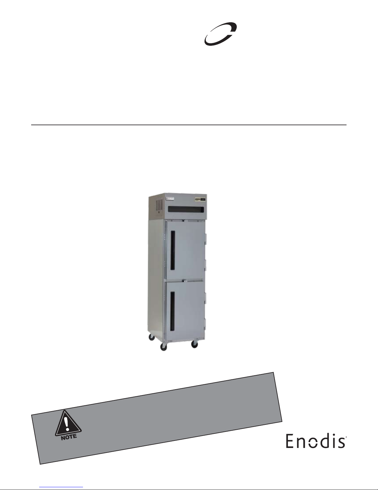
6000XL & 6100XL Series Reach Ins -
Delfield
™
®
All units manufactured after December 1st, 2007
Service, Installation and Care Manual
Please read this manual completely before attempting to install or operate this equipment! Notify carrier of
damage! Inspect all components immediately. See page 2.
IMPORTANT INFORMATION
READ BEFORE USE
PLEASE SAVE THESE INSTRUCTIONS!
Refrigerators and Freezers
Effective Date December 2007
6000XL Series Service and Installation Manual
Delfield
™
®
CONTENTS
RECEIVING & INSPECTING EQUIPMENT..................................2
SPECIFICATIONS ........................................................................3
INSTALLATION .......................................................................... 4
OPERATION ................................................................................ 5
MAINTENANCE .......................................................................6-7
WIRING DIAGRAMS .............................................................8-12
COMPRESSOR DIAGRAM .......................................................13
PARTS LISTING ..................................................................14-15
STANDARD LABOR GUIDELINES ............................................16
STANDARD WARRANTIES .................................................17-18
©2007 The Deleld Company. All rights reserved. Reproduction without
written permission is prohibited. “Deleld” is a registered trademark of The
Deleld Company.
RECEIVING AND INSPECTING THE EQUIPMENT
Even though most equipment is shipped crated, care should
be taken during unloading so the equipment is not damaged
while being moved into the building.
1. Visually inspect the exterior of the package and skid or
container. Any damage should be noted and reported to
the delivering carrier immediately.
2. If damaged, open and inspect the contents with the
carrier.
3. In the event that the exterior is not damaged, yet upon
opening, there is concealed damage to the equipment
notify the carrier. Notification should be made verbally
The serial number of all self-contained 6000XL Series
refrigerators and freezers is located above the door under the
shroud.
Always have the serial number of your unit available when
calling for parts or service. A complete list of authorized
Delfield parts depots is available at www.delfield.com.
This manual covers standard units only. If you have a custom
unit, consult the customer service department at the number
listed below.
4. Request an inspection by the shipping company of the
5. Be certain to check the compressor compartment
6. Freight carriers can supply the necessary damage forms
7. Retain all crating material until an inspection has been
SERIAL NUMBER INFORMATION
as well as in written form.
damaged equipment. This should be done within 10
days from receipt of the equipment.
housing and visually inspect the refrigeration package.
Be sure lines are secure and base is still intact.
upon request.
made or waived.
NOTE: Upon powering unit, there could be up to a
10 minute delay before unit begins to cool.
2
For customer service, call (800) 733-8829, (800) 733-8821, Fax (888) 779-2040, www.delfield.com
Delfield
™
®
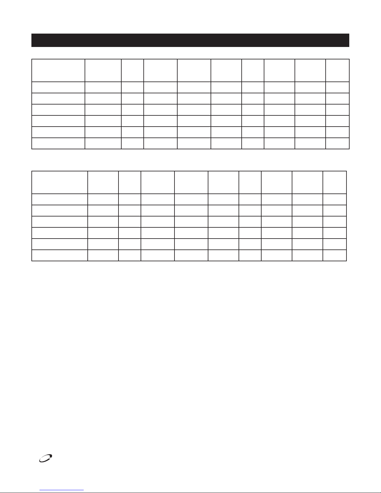
SPECIFICATIONS
6000XL Series Service and Installation Manual
STORAGE
MODEL VOLTAGE AMPS
6025XL-SH,S,G,GH 115 6.0 20 15.1 2092 20˚F 12.5 274 515P
6125XL-S,SH 115 9.0 20 15.1 2092 -20˚F 12.5 274 515P
6051XL-SH,S,G,GH 115 8.0 43.5 33.2 2488 20˚F 12.5 454 515P
6151XL-S,SH 115 12.0 43.5 33.2 1923 -20˚F 12.5 454 515P
6076XL-SH,S,G,GH 115 16.0 66.5 48.3 2092/2488 20˚F 12.5/12.5 622 520P
6176XL-S,SH 115/208-230 15.0 66.5 48.3 1516/1923 -20˚F 12.5/12.5 622 1420P
MODEL VOLTAGE AMPS
6025XLR-SH,S,G,GH 110 2.0 20 15.1 2092 20˚F 12.5 274 515P
6125XLR-S,SH 110 2.0 20 15.1 2092 -20˚F 12.5 274 515P
6051XLR-SH,S,G,GH 110 3.0 43.5 33.2 2488 20˚F 12.5 454 515P
6151XLR-S,SH 110 3.0 43.5 33.2 1923 -20˚F 12.5 454 515P
6076XLR-SH,S,G,GH 110 5.0 66.5 48.3 2092/2488 20˚F 12.5/12.5 622 515P
CAPACITY
FT3
STORAGE
CAPACITY
FT3
SHELF
CAPACITY
FT2
SHELF
CAPACITY
FT2
BTU/HR
REQUIRED
BTU/HR
EVAP.
TEMP
EVAP.
TEMP
R-404A
CHARGE
OZ.
R-404A
CHARGE
OZ.
SHIPPING
WEIGHT
SHIPPING
WEIGHT
NEMA
PLUG
TYPE
NEMA
PLUG
TYPE
6176XLR-S,SH 110 5.0 66.5 48.3 1516/1923 -20˚F 12.5/12.5 622 515P
For customer service, call (800) 733-8829, (800) 733-8821, Fax (888) 779-2040, www.delfield.com
3
6000XL Series Service and Installation Manual
Delfield
™
®
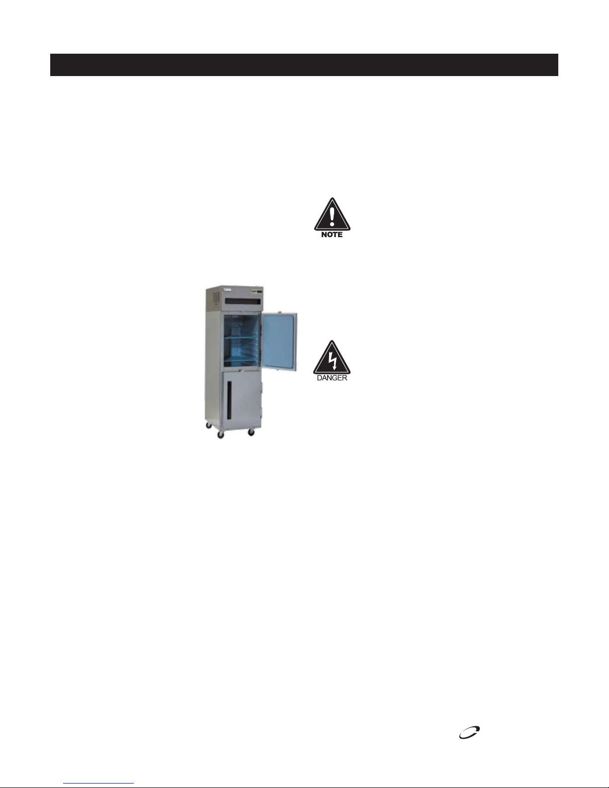
INSTALLATION
Location
Units represented in this manual are intended for indoor use
only. Be sure the location chosen has a floor strong enough
to support the total weight of the cabinet and contents. A fully
loaded 6000XL series can weigh as much as 1500 pounds.
Reinforce the floor as necessary to provide for maximum
loading. For the most efficient refrigeration, be sure to provide
good air circulation inside and out.
Inside cabinet: Do not pack refrigerator so full that air
cannot circulate. The refrigerated air is discharged at the top
rear of the unit. It is important to allow for proper air flow
from the top rear to the bottom of the unit. Obstructions to
this air flow can cause evaporator coil freeze ups and loss of
temperature or overflow of water from the evaporator drain
pan. The rear of the unit has molded ribs and the shelves
have a rear turn up on them to
prevent this. However, bags and
other items can still be located to
the far rear of the cabinet. There is
also a return air diffuser along the
top front of the cabinet interior, this
also requires proper air circulation.
Prevent obstruction by locating large
boxes and tall stacks of product to
the bottom of the cabinet.
Outside cabinet: Be sure that the
unit has access to ample air. Avoid
hot corners and locations near
stoves and ovens.
It is recommended that the unit be installed no closer than 2”
from any wall with at least 12” of clear space above the unit.
Avoid exposing glass door units to direct sunlight. Direct
sunlight through the glass doors will make the ABS liner
fade and become brittle and will greatly reduce refrigeration
efficiency.
Leveling
A level cabinet looks better and will perform better because
the doors will line up with the frames properly, the cabinet will
not be subject to undue strain and the contents of the cabinet
will not move around on the shelves. Use a level to make sure
the unit is level from front to back and side to side. Units
supplied with legs will have adjustable bullet feet to make the
necessary adjustments. If the unit is supplied with casters, no
adjustments are available. Ensure the floor where the unit is to
be located is level.
Stabilizing
Some models are supplied on casters for your convenience,
ease of cleaning underneath and for mobility. It is very
important, however, that the cabinet be installed in a stable
condition with the front wheels locked while in use.
Should it become necessary to lay the unit on its side or back
for any reason, allow at least 24 hours before start-up so as to
allow compressor oil to flow back to the sump. Failure to meet
this requirement can cause compressor failure and unit damage.
Unit repairs will not be subject to standard
unit warranties due to improper installation
procedures.
Electrical connection
Refer to the amperage data on page 3, the serial tag, your
local code or the National Electrical Code to be sure the unit is
connected to the proper power source. A protected circuit of
the correct voltage and amperage must be run for con nec tion
of the line cord, or permanent connection to the unit.
The thermostat must be turned to OFF and
the unit disconnected from the power source
whenever performing service, maintenance
functions or cleaning the refrigerated area.
Door Reversal Procedure 6000XL
Edge-Mount Hinge
1. Open door 90˚and lift door staight up and off hinges.
2. Remove the plastic screw covers on each hinge section by
prying out with a thin screwdriver.
3. Removve two outer screws that mount each hinge to door,
loosen the center screw, rotate hinge 180˚, reinstall outer
screws and retighten center screw.
4. Remove two screws that mount lock on top of door, turn
door up-side-down and remount lock to top of door.
5. Remove the hinges from the cabinet face frame.
6. Remove the stainless steel screws at the new hinge locations and install them where the hinge was removed from the
cabinet.
7. Using the screws removed in step 5, attach the hinges to
the new location on the cabinet face frame.
8. Remove the plastic cam from the hinges by pulling straight
up, then rotating the cam 180˚ and pushing back into the
hinge.
9. Reinstall the plastic screw covers removed in step 2.
10. Reinstall the door by reversing step 1.
4
For customer service, call (800) 733-8829, (800) 733-8821, Fax (888) 779-2040, www.delfield.com

Delfield
™
®
OPERATION
OPERATION
Electronic Temperature Control
Operation:
The electronic temperature control constantly monitors box
temperature as well as evaporator coil temperature to maintain
consistent product temperatures. The control also sends
temperature readings to the digital temperature display. The
control circuits continually self-check and if an error occurs,
the digital display will switch from temperature read-out to
error read-out, i.e. E 1. Even when an error is displayed, the
refrigeration and controls system should continue to function,
however not at optimal performance. Whenever the display
has an error read-out, Delfield Service should be contacted.
At initial start-up or anytime power is disconnected, then
reconnected to the unit, the control will delay all operations for
a short time (up to 10 minutes.) While in this delay period,
the control initializes the control parameters and confirms
that the temperature sensors and circuits are operational.
The digital temperature display will not display temperature
OR errors until the self-check is complete and the control
has switched on the evaporator fan motor, compressor and
condenser fan motor.
Refrigerator:
The control is located in the control box in the top of the
refrigerator behind the removable louvered panel on the left
side. It is factory set at mid-range to maintain about 38˚F
(3˚C) box temperature. To adjust for colder temperatures,
turn the knob clockwise. For warmer temperatures, turn the
knob counter-clockwise. Turn the knob fully counter-clockwise
to turn the refrigeration system off. Never turn the knob more
than 1 dial number and always allow 8 hours for temperature
stabilization before making any additional adjustments.
Freezer:
The control is located in the control box in the top of the
refrigerator behind the removable louvered panel on the left
side. It is factory set at mid-range to maintain about -3˚F
(-18˚C) box temperature. To adjust for colder temperatures,
turn the knob clockwise. For warmer temperatures, turn the
knob counter-clockwise. Turn the knob fully counter-clockwise
to turn the refrigeration system off. Never turn the knob more
than 1 dial number and always allow 8 hours for temperature
stabilization before making any additional adjustments.
Energy Saver Switch
The energy saver switch is a rocker switch located next to
the thermostat knob. The switch controls power to the frame
heater to minimize condensation around the door opening.
Press the switch to the “0” position to conserve energy. If
excessive condensation is observed on the door opening,
press the switch to the “-” position, (red portion of the rocker
will be visible).
6000XL Series Service and Installation Manual
Refrigeration & Defrost Cycle
Refrigerator:
Whenever the refrigerator is plugged in, and the control
has completed initializing, the evaporator fans will run
continuously and the digital temperature will display box
temperature in degrees F. The temperature control will cycle
the compressor and condenser fan motor to maintain box
temperature at the control setting.
Refrigerator Defrost
The temperature control also monitors the evaporator
temperature and will turn off the compressor and condenser
fan motor when needed to allow accumulated frost on the
evaporator to clear. During this defrost cycle, the digital
temperature display will read dEF. After the defrost cycle is
complete, the temperature control will return to a normal
cooling cycle, but the display will continue to read dEF until
the evaporator returns to normal cooling temperatures (up to
30 minutes).
Freezer:
Whenever the freezer is plugged in, and the control
has completed initializing, the evaporator fans will run
continuously. After evaporator coil has reached operational
temperature, the digital temperature will display box
temperature in degrees F. The temperature control will cycle
the compressor and condenser fan motor to maintain box
temperature at the control setting.
Freezer Defrost
The control also monitors compressor total running time
and will enter a defrost cycle after total compressor running
time is greater than 4-hours since the last defrost cycle OR
if evaporator coil temperature drops below -34˚F (indicating
excessive frost on the coil).
When the control enters the defrost mode, it switches OFF the
evaporator fan motor, compressor, and condenser fan motor,
and switches ON the defrost heater to warm the evaporator
coil thereby melting all frost accumulated during the previous
refrigeration cycle. The digital temperature display will now
read dEF. The control will continue the defrost cycle for a
MINIMUM of 8 minutes and a MAXIMUM of 30 minutes
depending on the amount of frost accumulated on the
evaporator coil.
After the defrost cycle is complete, the control returns to a
normal refrigeration cycle, however the evaporator fan motor
will not switch on for 2 minutes AFTER the compressor and
condenser fan motor have begun operating. The digital
temperature display will continue to read dEF until the
evaporator has returned to normal freezing temperatures (up
to 30 minutes).
For customer service, call (800) 733-8829, (800) 733-8821, Fax (888) 779-2040, www.delfield.com
5
6000XL Series Service and Installation Manual
Delfield
™
®
MAINTENANCE
The thermostat must be turned to OFF and
the unit disconnected from the power source
whenever performing service, maintenance
functions or cleaning the refrigerated area.
Refrigerators and Freezers
The interior and exterior can be cleaned using soap and warm
water. If this isn’t sufficient, try ammonia and water or a
nonabrasive liquid cleaner. When cleaning the exterior, always
rub with the “grain” of the stainless steel to avoid marring the
finish.
Do not use an abrasive cleaner because it will scratch the
stainless steel and plastic and can damage the breaker strips
and gaskets.
Cleaning the Condenser Coil
The condenser coil requires regular cleaning, recommended
is every 90 days. In some instances though you may find
that there is a large amount of debris and dust or grease
accumulated prior to the 90 day time frame. In these cases the
condenser coil should be cleaned every 30 days.
If the build up on the coil consists of only light dust and debris
the condenser coil can be cleaned with a simple brush, heavier
dust build up may require a vacuum or even compressed air to
blow through the condenser coil.
If heavy grease is present there are de-greasing agents
available for refrigeration use and specifically for the condenser
coils. The condenser coil may require a spray with the degreasing agent and then blown through with compressed air.
Stainless Steel Care and Cleaning
To prevent discoloration or rust on stainless steel several
important steps need to be taken. First, we need to understand
the properties of stainless steel. Stainless steel contains
70-80% iron which will rust. It also contains 12-30%
chromium which forms an invisible passive film over the steels
surface which acts as a shield against corrosion. As long as
the protective layer is intact, the metal is still stainless. If the
film is broken or contaminated, outside elements can begin to
breakdown the steel and begin to form rust of discoloration.
Proper cleaning of stainless steel requires soft cloths or plastic
scouring pads.
NEVER USE STEEL PADS, WIRE BRUSHES OR
SCRAPERS!
Cleaning solutions need to be alkaline based or non-chloride
cleaners. Any cleaner containing chlorides will damage
the protective film of the stainless steel. Chlorides are also
commonly found in hard water, salts, and household and
industrial cleaners. If cleaners containing chlorides are
used be sure to rinse repeatedly and dry thoroughly upon
completion.
Routine cleaning of stainless steel can be done with soap and
water. Extreme stains or grease should be cleaned with a
non-abrasive cleaner and plastic scrub pad. It is always good
to rub with the grain of the steel. There are also stainless steel
cleaners available which can restore and preserve the finish of
the steels protective layer.
Failure to maintain a clean condenser coil can initially cause
high temperatures and excessive run times, continuous
operation with dirty or clogged condenser coils can result in
compressor failures. Neglecting the condenser coil cleaning
procedures will void any warranties associated with the
compressor or cost to replace the compressor.
Never use a high pressure water wash for this
cleaning procedure as water can damage the
electrical components located near or at the
condenser coil.
In order to maintain proper refrigeration performance, the
condenser fins must be cleaned of dust, dirt and grease
regularly. It is recommended that this be done at least every
three months. If conditions are such that the condenser is
totally blocked in three months, the frequency of cleaning
should be increased. Clean the condenser with a vacuum
cleaner or stiff brush. If extremely dirty, a commercially
available condenser cleaner may be required.
6
For customer service, call (800) 733-8829, (800) 733-8821, Fax (888) 779-2040, www.delfield.com
Early signs of stainless steel breakdown can consist of small
pits and cracks. If this has begun, clean thoroughly and start
to apply stainless steel cleaners in attempt to restore the
passivity of the steel.
Never use an acid based cleaning solution!
Many food products have an acidic content
which can deteriorate the finish. Be sure to
clean the stainless steel surfaces of ALL food
products. Common items include, tomatoes,
peppers and other vegetables.
 Loading...