

Page 1

500 Series
Service and Installation Manual
Please read this manual completely before attempting to install or operate this equipment! Notify carrier of damage! Inspect all
components immediately. See page 2.
IMPORTANT INFORMATION
READ BEFORE USE
PLEASE SAVE THESE INSTRUCTIONS!
April 2010
Page 2

500 Series Display Cases Service and Installation Manual
CONTENTS SERIAL NUMBER LOCATION
RECEIVING & INSPECTING EQUIPMENT ..............................2
SPECIFICATIONS ..................................................................3
PRESSURE CONTROL SETTINGS .........................................5
INSTALLATION ................................................................. 5, 6
OPERATION ..................................................................... 5, 6
CARE & CLEANING ..............................................................6
WIRING DIAGRAMS
500-CR self-contained refrigerated units .......................
500-OR open refrigerated units .....................................
500-CD dry storage units ..............................................
500-CH curved heated units ..........................................
EXPLODED VIEWS & PARTS LISTS
537-CD ..........................................................................
549-CD ..........................................................................
561-CD ........................................................................
573-CD ........................................................................
537-CR, CRR ...............................................................
549-CR, CRR ...............................................................
561-CR, CRR ...............................................................
573-CR, CRR ...............................................................
549-CH ........................................................................
561-CH ........................................................................
573-CH ........................................................................14
549-OR ........................................................................
FLUORESCENT LIGHT ASSEMBLY .....................................15
DOOR ASSEMBLY ...............................................................16
REFRIGERATION ASSEMBLES............................................17
FOOD WELL ASSEMBLY .....................................................18
REPLACEMENT PARTS LIST ..............................................19
STANDARD LABOR GUIDELINES ........................................20
STANDARD WARRANTIES ............................................ 21-22
NOTES ................................................................................23
The Serial number on all 500 Series units is located on the
rear of the unit, near the ON/OFF switch.
Always have the serial number of your unit available when
calling for parts or service. A complete list of authorized
Delfield parts depots can be found at www.delfield.com.
7
©2010 The Delfield Company. All rights reserved. Reproduction without
7
written permission is prohibited. “Delfield” is a registered trademark of The
Delfield Company.
8
8
9
9
10
10
11
11
12
12
13
13
14
RECEIVING AND INSPECTING THE EQUIPMENT
Even though most equipment is shipped crated, care should
be taken during unloading so the equipment is not damaged
while being moved into the building.
1. Visually inspect the exterior of the package and skid or
container. Any damage should be noted and reported
to the delivering carrier immediately.
2. If damaged, open and inspect the contents with the
carrier.
3. In the event that the exterior is not damaged, yet upon
opening, there is concealed damage to the equipment
notify the carrier. Notification should be made verbally
as well as in written form.
4. Request an inspection by the shipping company of the
damaged equipment. This should be done within 10
days from receipt of the equipment.
5. Check the lower portion of the unit to be sure adjustable
feet are not bent.
2
For customer service, call (800) 733-8829, (800) 773-8821, Fax (989) 773-3210, www.delfield.com
6. Also open the compressor compartment housing and
visually inspect the refrigeration package. Be sure lines
are secure and base is still intact.
7. Freight carriers can supply the necessary damage forms
upon request.
8. Retain all crating material until an inspection has been
made or waived.
Uncrating the Equipment
First cut and remove the banding from around the crate.
Remove the front of the crate material, use of some tools will
be required. If the unit is on legs remove the top of the crate
as well and lift the unit off the skid.
Page 3

500 Series Display Cases Service and Installation Manual
500 SERIES SPECIFICATIONS
MODEL DELFIELD VOLTS/HERTZ AMPS
NUMBER PART # PHASE (includes lights & fan)
Dry Storage Display Cases
537-CD 078-5371 115/60/1 5.0
549-CD 078-5491 115/60/1 5.0
561-CD 078-5611 115/60/1 5.0
573-CD 078-5731 115/60/1 5.0
MODEL DELFIELD NUMBER OF VOLTS/HERTZ
NUMBER PART # 12 X 20 WELLS PHASE AMPS
Heated Display Cases
549-CH 078-5494 3 120, 208-240V/60/1 19.0/21.0
561-CH 078-5614 4 120, 208-240V/60/1 24.0/27.0
573-CH 078-5734 5 120, 208-240V/60/1 30.0/34.0
MODEL DELFIELD VOLTS/HERTZ EVAPORATOR CAPACITY CABINET LOAD
NUMBER PART # H.P.* PHASE AMPS BTU/°TD BTU/HOUR
Remote Refrigerated Display Cases
537-CRR CONSULT FACTORY 1/2* 115/60/1 5.0 180 1730
549-CRR 078-5493 1/2* 115/60/1 5.0 190 2250
561-CRR 078-5613 3/4* 115/60/1 6.0 190 2770
573-CRR 078-5733 3/4* 115/60/1 6.0 290 3290
*Recommended horsepower
MODEL DELFIELD VOLTS/HERTZ CABINET LOAD SYSTEM CAPACITY REFRIGERATION
NUMBER PART # H.P. PHASE AMPS BTU/HOUR BTU/HOUR CHARGE 404A
Self-Contained Refrigerated Display Cases
537-CR 078-5372 1/2 115/60/1 12.0 1730 3258 32 oz.
549-CR 078-5492 1/2 115/60/1 12.0 2250 3316 32 oz.
561-CR 078-5612 3/4 115/60/1 16.0 2770 4919 48 oz.
573-CR 078-5732 3/4 115/60/1 16.0 3290 5387 48 oz.
MODEL DELFIELD VOLTS/HERTZ CABINET LOAD SYSTEM CAPACITY REFRIGERATION
NUMBER PART# H.P. PHASE AMPS BTU/HOUR BTU/HOUR CHARGE 404A
Open Front Refrigerated Display Cases
549-OR 078-5495 1/2 115/60/1 12.0 2030 3354 32 oz.
For customer service, call (800) 733-8829, (800) 773-8821, Fax (989) 773-3210, www.delfield.com
3
Page 4

500 Series Display Cases Service and Installation Manual
CAUTION
INSTALLATION: 500 CD, CR, CRR & OR
Location
To meet NSF standards, all units must be sealed
to the floor.
Be sure the location chosen has a floor strong enough
to support the total weight of the cabinet and contents.
Contents fully loaded in this product line can weigh as much
as 1500 lbs. Reinforce the floor as necessary to provide for
maximum loading.
For the most efficient refrigeration, be sure to provide good
air circulation inside and out. Do not pack the refrigerator so
full that air cannot circulate. Be sure that the exterior of the
unit has access to ample air. Avoid hot corners and locations
near stoves and ovens.
Leveling
To level unit, simply lower the four adjustable rubber feet
located under the unit to the floor and adjust until unit is
level. A level cabinet will perform better because the drain
will empty properly, the doors will line up with the frames
correctly and the cabinet will not be subject to undue strain.
Plumbing
Self-contained models are standard with a condensate
evaporator. If the evaporator fails, the unit’s drain must have
an outlet to an appropriate drainage area or container.
Moisture collecting from improper drainage
can create a slippery surface on the floor and
a hazard to employees. It is the owner’s and
operator’s responsibility to provide a container or
outlet for drainage.
Electrical connection
Refer to the amperage data on page 3, the serial tag, your
local code or the National Electrical Code to be sure the
unit is connected to the proper power source. A protected
circuit of the correct voltage and amperage must be run for
connection of the line cord, or permanent connection to the
unit.
Self-contained units have an ON/OFF switch located on
the operators side. Simply turn the switch to ON to begin
operation.
The power switch should be turned to OFF and the
unit disconnected from the power source whenever
performing service or maintenance functions.
OPERATION: 500 CD, CR, CRR & OR
On self-contained models, after turning the ON/OFF switch
to ON, the unit’s compressor will begin operating. Delfield
display cases are designed to maintain an operational
temperature of 36°F to 40°F.
Do not load the storage area in a way that restricts the air
flow. Overloading will result in the loss of temperature. Do
not throw items into the storage area. The interior of the
cabinet and the blower coil may be damaged by this type of
neglect, which is not covered under your warranty.
4
For customer service, call (800) 733-8829, (800) 773-8821, Fax (989) 773-3210, www.delfield.com
These units use HFC-404A refrigerant, and
have a lock-out high pressure limiting device.
Under severe overloading conditions, in the
event of a condenser fan failure or a plugged or
blocked condenser, this device may shut down
the refrigeration system. See page 17 for part number
information if a replacement is required.
Page 5

CONTROL SETTINGS: 500 CR & OR
Pressure Control
The temperature is controlled by an adjustable pressure
control located in the machine compartment. An adjustable
control has the word COLDER near the knob, with an arrow
to indicate the adjustment direction. These controls are
field adjustable and do not require a service agent. If you
have any questions, feel free to contact the Delfield Service
Department.
The refrigeration systems on self-contained CR & OR models
were adjusted at the factory to maintain between 36°F and
40°F. No adjustment should be necessary. If adjustment
does become needed however, the factory recommended
settings are:
Low-pressure settings (CR models): 82 psi cut-in,
47 psi cut-out, 35 psi differential.
Low-pressure settings (OR models): 82 psi cut-in,
40 psi cut-out, 42 psi differential.
Operating pressures: High, 170 to 200 psi. Low, 30 to 37
psi.
500 Series Display Cases Service and Installation Manual
In attempting to adjust the pressure control, you can
do damage to your unit by accidentally adjusting the
differential. Please make small incremental adjustments
if a temperature adjustment is necessary, please contact
the service department at Delfield (800) 733-8829 #1,
or your local service agent. Delfield is not responsible
for charges incurred while having the pressure control
adjusted.
For customer service, call (800) 733-8829, (800) 773-8821, Fax (989) 773-3210, www.delfield.com
5
Page 6

500 Series Display Cases Service and Installation Manual
S
T PE
S
INSTALLATION: 500 CH
Installation should be done by personnel
certified and licensed to install and maintain
electrical appliances.
Location
Be sure the location chosen has a floor strong enough
to support the total weight of the cabinet and contents.
Contents fully loaded into this product line can weigh as
much as 1500 lbs. Reinforce the floor as necessary to
provide for maximum loading.
OPERATION: 500 CH
NOTE: Intended for DRY OPERATION ONLY.
Before the unit is used the first time for serving, turn the
temperature knob to “10” and heat the well for 20 minutes.
Do not be alarmed if smoke appears; this preheat should
burn off any residue or dust on the heating element.
Hot surfaces can cause serious burns. Always
wear some type of protective covering on your
hands and arms when removing lids or pans
from the unit.
Never place food directly into the well. Always use pans.
Always place covers on pans when not serving to prevent
food from drying out and to reduce your operating cost.
Leveling
A level cabinet looks better and will perform better because
the drain pan will drain properly, the doors will line up with
the frames properly, and the cabinet will not be subject to
undue strain.
Electrical connection
Connections must be made in accordance with
all applicable local codes and/or the National
Electrical Code. Refer to the wiring diagrams on
pages 6 and 7.
For most efficient operation, keep covered insets empty in
each well during preheating and when the well is not in use.
Dry operation
1) Pre-heat the well on “HIGH” for approximately
15 minutes.
2) After pre-heating, set the control to your
desired serving temperature.
Only 6” (15.2cm) deep insets should be used with a dry
food well. When operated dry, the bottom of the food well
will discolor. Refer to cleaning instructions to remove
discoloration.
Temperature
Product in pans . . . . . . . . . . . . . . . . . . . . . . 140°F to 160°F
CLEANING: ALL MODELS
Clean the food wells daily. Wash with non-abrasive cleanser
and non-abrasive pad. If necessary, a mild abrasive may be
used. Do not use steel wool.
For all stainless steel parts, use mild, non-abrasive soap
or detergent and warm water. This may be followed by an
application of stainless steel cleaner or polish which will
eliminate water spotting and fingerprints and will bring out
the finish of the stainless steel.
Do not use a hose or pressure wash on these
units. The water will damage the electrical
components.
6
For customer service, call (800) 733-8829, (800) 773-8821, Fax (989) 773-3210, www.delfield.com
Cleaning the condenser (refrigerated units)
In order to maintain proper refrigeration, the condenser
fins must be cleaned of dust, dirt and grease every three
months. If condenser is totally blocked after three months
increase cleaning frequency. Clean the condenser with a
vacuum cleaner or stiff brush. If extremely dirty, use a
commercially available condenser cleaner.
Cleaning the sliding door assembly
All Delfield 500 Series display cases feature a Pike sliding
door assembly. Regular cleaning of door tracks with mild
soap and water will keep them free of foreign matter
insuring many years of use. The glass may be cleaned with
a glass cleaner.
Page 7
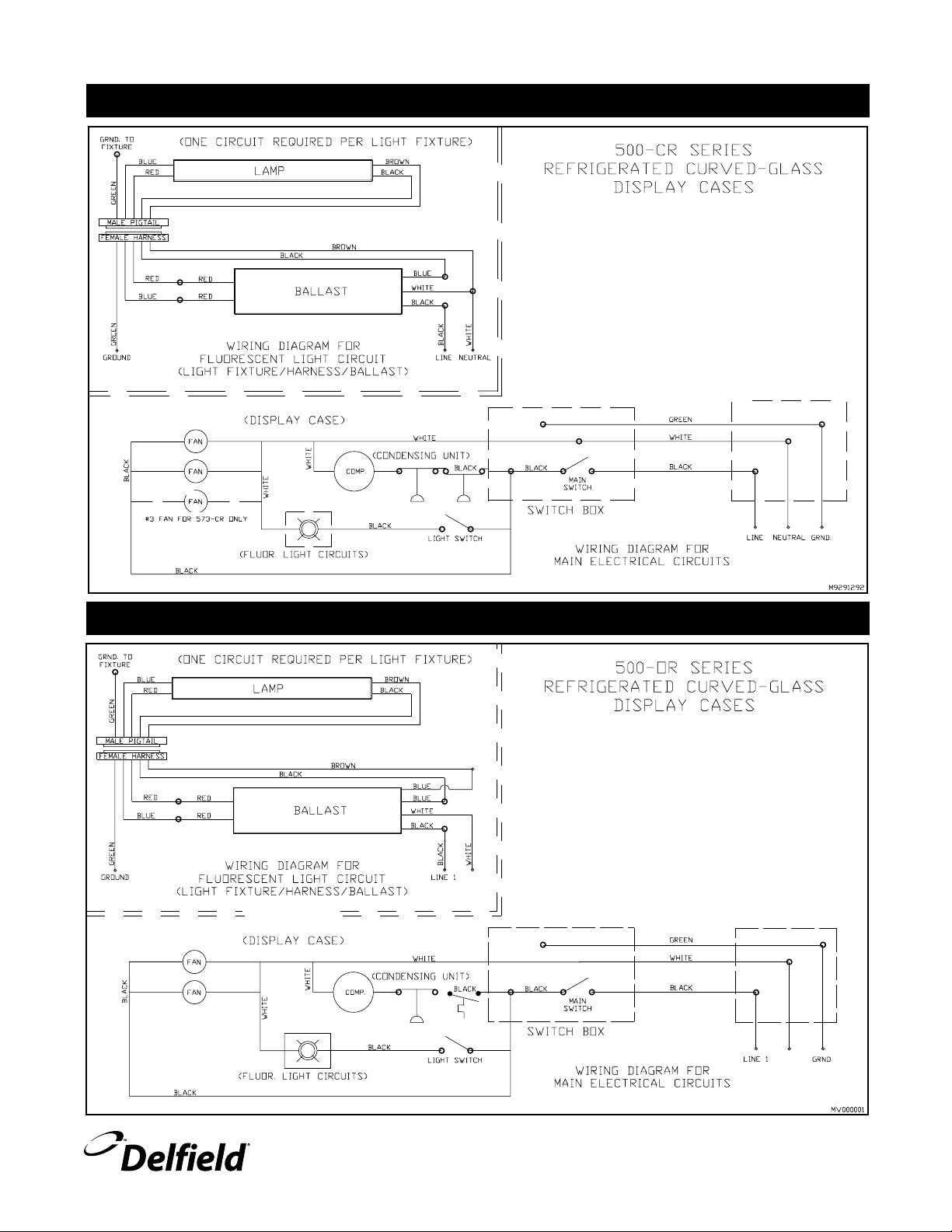
WIRING: 500 CR
NEUTRAL
NEUTRAL
500 Series Display Cases Service and Installation Manual
WIRING: 500 OR
For customer service, call (800) 733-8829, (800) 773-8821, Fax (989) 773-3210, www.delfield.com
7
Page 8

500 Series Display Cases Service and Installation Manual
WHT
WHT
WHT
WHT
WHT
WHT
WHT
WHT
WHT
WHT
WHT
WHT
WHT
WHT
J
P P P P
RED
RED
RED
RED
RED
RED
RED
HEATED SHELF
120V
P LL
2
1
H
H
1 2
208V208V208V
21
P L L
2
H
H
1
21
LLP
2
H
H
1
2LL1
P
H
2
1
H
BLK
BLK
BLK
BLK
BLK
BLK
BLK
BLK
BLK
BLK
BLK
BLK
BLK
WIRING: 500 CD
WIRING: 500 CH
8
For customer service, call (800) 733-8829, (800) 773-8821, Fax (989) 773-3210, www.delfield.com
Page 9

500 Series Display Cases Service and Installation Manual
13 12 6
2
4
10
9
11
7
3
5
1
1615
14
8
6
REPLACEMENT PARTS LIST FOR 537-CD
DELFIELD
KEY QUANTITY PART# DESCRIPTION
1 1 001-3133 mirror, acrylic, RH, 500-CD
2 1 001-3134 mirror, acrylic, LH, 500-CD
3 1 397-8121 holder, adj. shelf, RH
4 1 397-8120 holder, adj. shelf, LH
5 2 001-5285 diffuser, air 537-CD/CR
6 2 XMK00127 fixture, flour. light, 24 remote
7 4 001-5407 support, shelf, 537-CD/CR
8 2 001-5026 clip, air diffuser, 537-CD
9 1 397-8137 shelf, adjustable, 21” x 33”
10 1 397-8138 shelf, adjustable, 26” x 33”
11 1 323-7490 door set, with lock, 537-CD/CR
12 4 932-1095 stud, threaded, s/s, 1/4-20 x .75
13 4 932-1401 nut, 1/4-20, locking
Please Note: Items not shown on exploded view are listed on page 17.
Door locks #323-3986 & door keys #323-3988
REPLACEMENT PARTS LIST FOR 549-CD
DELFIELD
KEY QUANTITY PART# DESCRIPTION
1 1 001-3133 mirror, acrylic, RH, 500-CD
2 1 001-3134 mirror, acrylic, LH, 500-CD
3 1 397-8121 holder, adj. shelf, RH
4 1 397-8120 holder, adj. shelf, LH
5 2 XMK00128 fixture, flour. light, 36 remote
6 4 001-5235 shelf support
7 2 397-8122 shelf, top
8 2 397-8123 shelf, bottom
9 1 323-4697 door assembly, with lock
10 1 216-2677 fan, axial
Please Note: Items not shown on exploded view are listed on page 17.
Door locks #323-3986 & door keys #323-3988
For customer service, call (800) 733-8829, (800) 773-8821, Fax (989) 773-3210, www.delfield.com
9
Page 10

500 Series Display Cases Service and Installation Manual
REPLACEMENT PARTS LIST FOR 561-CD
DELFIELD
KEY QUANTITY PART# DESCRIPTION
1 1 001-3133 mirror, acrylic, RH, 500-CD
2 1 001-3134 mirror, acrylic, LH, 500-CD
3 1 397-8121 holder, adj. shelf, RH
4 1 397-8120 holder, adj. shelf, LH
5 2 XMK00129 fixture, flour. light, 48 remote
6 4 001-5277 shelf support
7 2 397-8122 shelf, top
8 2 397-8123 shelf, bottom
9 1 323-4698 door assembly, PIKE, with lock
10 1 216-2677 fan, axial
11 1 397-8125 shelf, top center
12 1 397-8126 shelf, bottom center
Please Note: Items not shown on exploded view are listed on page 17.
Door locks #323-3986 & door keys #323-3988
REPLACEMENT PARTS LIST FOR 573-CD
DELFIELD
KEY QUANTITY PART# DESCRIPTION
1 1 001-3133 mirror, acrylic, RH, 500-CD
2 1 001-3134 mirror, acrylic, LH, 500-CD
3 1 397-8121 holder, adj. shelf, RH
4 1 397-8120 holder, adj. shelf, LH
5 2 XMK00130 fixture, flour. light, 60 remote
6 4 001-5295 shelf support
7 2 397-8122 shelf, top
8 2 397-8123 shelf, bottom
9 1 323-4699 door assembly, PIKE, with lock
10 1 216-2677 fan, axial
11 1 397-8127 shelf, top center
12 1 397-8128 shelf, bottom center
Please Note: Items not shown on exploded view are listed on page 17.
Door locks #323-3986 & Pike door keys #323-3988
10
For customer service, call (800) 733-8829, (800) 773-8821, Fax (989) 773-3210, www.delfield.com
Page 11

500 Series Display Cases Service and Installation Manual
13 12 6
2
4
10
9
11
7
3
5
1
1615
14
8
6
REPLACEMENT PARTS LIST FOR 537CR/CRR
DELFIELD
KEY QUANTITY PART# DESCRIPTION
1 1 001-3131 mirror, acrylic, RH, 500-CR
2 1 001-3132 mirror, acrylic, LH, 500-CR
3 1 397-8121 holder, adj. shelf, RH
4 1 397-8120 holder, adj. shelf, LH
5 2 001-5285 diffuser, air 537-CD/CR
6 2 XMK00127 fixture, flour. light, 24 remote
7 4 001-5407 support, shelf, 537-CD/CR
8 1 001-5407 divider, air flow, 537-CR
9 1 397-8137 shelf, adjustable, 21” x 33”
10 1 397-8138 shelf, adjustable, 26” x 33”
11 1 323-7490 door set, with lock, 537-CD/CR
12 4 932-1095 stud, threaded, s/s, 1/4-20 x .75
13 4 932-1401 nut, 1/4-20, locking
14 1 001-5422 cover, coil, 537-CR
15 4 001-5252 clip, holding, coil cover
16 4 932-1238 screw, #8 x .75, H/N-P-TR-A
Please Note: Items not shown on exploded view are listed on page 17.
Door locks #323-3986 & door keys #323-3988
REPLACEMENT PARTS LIST FOR 549-CR/CRR
DELFIELD
KEY QUANTITY PART# DESCRIPTION
1 1 001-3133 mirror, acrylic, RH
2 1 001-3132 mirror, acrylic, LH
3 1 397-8121 holder, adj. shelf, RH
4 1 397-8120 holder, adj. shelf, LH
5 2 XMK00128 fixture, flour. light, 36 remote
6 4 001-5235 shelf support
7 2 397-8122 shelf, top
8 2 397-8123 shelf, bottom
9 1 323-4697 door assembly, with lock
Please Note: Items not shown on exploded view are listed on page 17.
Door locks #323-3986 & door keys #323-3988
For customer service, call (800) 733-8829, (800) 773-8821, Fax (989) 773-3210, www.delfield.com
11
Page 12

500 Series Display Cases Service and Installation Manual
REPLACEMENT PARTS LIST FOR 561-CR/CRR
DELFIELD
KEY QUANTITY PART# DESCRIPTION
1 1 001-3133 mirror, acrylic, RH
2 1 001-3132 mirror, acrylic, LH
3 1 397-8121 holder, adj. shelf, RH
4 1 397-8120 holder, adj. shelf, LH
5 2 XMK00129 fixture, flour. light, 48 remote
6 4 001-5277 shelf support
7 2 397-8122 shelf, top
8 2 397-8123 shelf, bottom
9 1 323-4698 door assembly, PIKE, with lock
10 1 397-8125 shelf, top center
11 1 397-8126 shelf, bottom center
Please Note: Items not shown on exploded view are listed on page 17.
Door locks #323-3986 & door keys #323-3988
REPLACEMENT PARTS LIST FOR 573-CR/CRR
DELFIELD
KEY QUANTITY PART# DESCRIPTION
1 1 001-3133 mirror, acrylic, RH
2 1 001-3132 mirror, acrylic, LH
3 1 397-8121 holder, adj. shelf, RH
4 1 397-8120 holder, adj. shelf, LH
5 2 XMK00130 fixture, flour. light, 60 remote
6 4 001-5295 shelf support
7 2 397-8122 shelf, top
8 2 397-8123 shelf, bottom
9 1 323-4699 door assembly, PIKE, with lock
10 1 397-8127 shelf, top center
11 1 397-8128 shelf, bottom center
Please Note: Items not shown on exploded view are listed on page 17.
Door locks #323-3986 & door keys #323-3988
12
For customer service, call (800) 733-8829, (800) 773-8821, Fax (989) 773-3210, www.delfield.com
Page 13

500 Series Display Cases Service and Installation Manual
15
7
6
5
3
4
34
10
16
12
2
13
11
1
14
9
8
15
7
6
5
3
4
34
10
16
12
2
13
11
1
14
9
8
REPLACEMENT PARTS LIST FOR 549-CH
DELFIELD
KEY PART# DESCRIPTION
1 323-4055 door set, 49” curved glass
2 345-5439 glass, curved, 1” insulated, 47”
3 219-3959 bulb, 25W, Teflon coated, clear
4 219-3960 lamp holder, twin-threaded
5 219-3970 heater, pad, 115V/90W
6 XMK00106 warmer, food, 208V, no drain
7 219-4212 switch, 30A 120/277V
8 219-0154 switch, rocker, 20A/125V, 15A/250V
9 351-6059 thermometer, digital, solar/batt
10 105-0183 extrusion, polyethylene, blk, vertical, RH
11 105-0173 extrusion, polyethylene, blk, vertical, LH
12 105-0184 extrusion, polyethylene, blk, curved, RH
13 105-0174 extrusion, polyethylene, blk, curved, LH
14 001-5414 trim, side, exterior, RH
15 001-5415 trim, side, exterior, LH
16 001-6855 trim, front, laminate
REPLACEMENT PARTS LIST FOR 561-CH
DELFIELD
KEY PART# DESCRIPTION
1 323-4068 door set, 61” curved glass
2 345-5441 glass, curved, 1” insulated, 59”
3 219-3959 bulb, 25W, Teflon coated, clear
4 219-3960 lamp holder, twin-threaded
5 219-3970 heater, pad, 115V/90W
6 XMK00106 warmer, food, 208V, no drain
7 219-4212 switch, 30A 120/277V
8 219-0154 switch, rocker, 20A/125V, 15A/250V
For customer service, call (800) 733-8829, (800) 773-8821, Fax (989) 773-3210, www.delfield.com
9 351-6059 thermometer, digital, solar/batt
10 105-0183 extrusion, polyethylene, blk, vertical, RH
11 105-0173 extrusion, polyethylene, blk, vertical, LH
12 105-0184 extrusion, polyethylene, blk, curved, RH
13 105-0174 extrusion, polyethylene, blk, curved, LH
14 001-5414 trim, side, exterior, RH
15 001-5415 trim, side, exterior, LH
16 001-6866 trim, front, laminate
13
Page 14

500 Series Display Cases Service and Installation Manual
11111111
9
8
7
16
12
2
11
13
14
1
6
5
3
4
10
34
15
14
13
16
9
8
14
25
23
24
22
21
12
11
15
20
19
9
10
18
17
18
17
10
43
2
1
5
6
7
REPLACEMENT PARTS LIST FOR 573-CH
DELFIELD
KEY
1 323-4069 door set, 73” curved glass
2 345-5443 glass, curved, 1” insulated, 71”
3 219-3959 bulb, 25W, Teflon coated, clear
4 219-3960 lamp holder, twin-threaded
5 219-3970 heater, pad, 115V/90W
6 XMK00106 warmer, food, 208V, no drain
7 219-4212 switch, 30A 120/277V
8 219-0154 switch, rocker, 20A/125V, 15A/250V
9 351-6059 thermometer, digital, solar/batt
10 105-0183 extrusion, polyethylene, blk, vertical, RH
11 105-0173 extrusion, polyethylene, blk, vertical, LH
12 105-0184 extrusion, polyethylene, blk, curved, RH
13 105-0174 extrusion, polyethylene, blk, curved, LH
14 001-5414 trim, side, exterior, RH
15 001-5415 trim, side, exterior, LH
16 001-6867 trim, front, laminate
PART# DESCRIPTION
REPLACEMENT PARTS LIST FOR 549-OR
DELFIELD
KEY
1 001-5558 baffle, fan 49”
2 216-2667 motor, fan, morrill
3 351-6075 blade, fan, 7” dia., aluminum
4 397-8070 bracket, fan motor
5 218-2414 harness, fan motor, 78”
6 351-6097 coil, evaporator, custom, 49”
7 351-6273 valve, expansion, 1/4, HI, 404A
8 XMK-00132 fixture, fluorescent light, 36”
9 001-5554 back, interior, louvered
10 001-5555 diffuser, air, LH & RH
14
For customer service, call (800) 733-8829, (800) 773-8821, Fax (989) 773-3210, www.delfield.com
11 105-0183 extrusion, polyethylene, blk, vert, RH
12 105-0173 extrusion, polyethylene, blk, vert, LH
13 105-0184 extrusion, polyethylene, blk, curved, RH
14 105-0174 extrusion, polyethylene, blk, curved, LH
15 001-5414 trim, side, exterior, RH
16 001-5415 trim, side, exterior LH
17 001-6855 trim, front, laminate, 549
18 001-5278 louvers, s/s, 15 x 17
19 351-6038 thermometer, dial
20 001-5243 panel, access
21 219-3903 ballast, rapid start, 36” lamp
22 219-3919 switch, 15A/120V
23 351-6247 control, pressure, high
24 509-0025 control, temperature, -30-100
25 352-6731 condensing unit, 1/2 hp, R-404A, med
PART# DESCRIPTION
Page 15

FLUORESCENT LIGHT
2
7
6
4
5
3
9
8
1
7
500 Series Display Cases Service and Installation Manual
DELFIELD
KEY
1 SMK00571 cap, end, top mtg, pigtail, -rem.
2 SMK00572 cap, end, top mtg, blank, -rem.
3 170-1045 diffuser, fluor. light, 24”
170-1046 diffuser, fluor. light, 36”
170-1047 diffuser, fluor. light, 48”
170-1054 diffuser, fluor. light, 60”
4 219-3906 lamp, fluorescent, 24”
219-3907 lamp, fluorescent, 36”
219-3908 lamp, fluorescent, 48”
219-3909 lamp, fluorescent, 60”
5 219-3939 lamp holder, left
6 219-3940 lamp holder, right
7 932-1266 screw, #8-32 x .50
8 218-3613 pigtail, male, 3.5”, rem. ballast
218-3595 pigtail, male, 9”, rem. ballast
9 932-1010 nut, hex, starlock, s/s, #6-32
*Refer to the exploded view of unit for a complete assembly part number
PART# DESCRIPTION
For customer service, call (800) 733-8829, (800) 773-8821, Fax (989) 773-3210, www.delfield.com
15
Page 16

500 Series Display Cases Service and Installation Manual
4
6
4
3
1
1
1
1
5
2
2
Door Assembly
DELFIELD
KEY
323-7490 complete assembly, 537-CD/CR/CRR
323-4697 complete assembly, 549-CD/CR/CRR
323-4055 complete assembly, 549-CH
323-4698 complete assembly, 561-CD
323-4699 complete assembly, 573-CD
1 323-4636 single roller, 537, 549 & 561
323-4637 double roller, 573
2 order by size bumper gasket, 241/8 & 537
323-3936 bumper gasket, 245/32, 549, 561 & 573
3 order by size wiper gasket, 537
323-3936 wiper gasket, 2223/32, 549, 561 & 573
4 323-3947 spring 12”, green, 537
323-3949 spring 12”, 549
323-3945 spring 23”, gold, 561
323-3946 spring 30”, gold, 573
5 order by size bottom track, 34 3/16, 537, black
323-3904 bottom track, 46 3/16, 549, black
order by size bottom track, 46 3/16, 549-CH, black
323-3909 bottom track, 58 3/16, 561, black
323-3912 bottom track, 70 3/16, 573, black
6 order by size top track, 34 3/16, 537, black
323-3904 top track, 46 3/16, 549, black
323-3922 top track, 58 3/16, 561
order by size Alum. top track, 46 3/16, 549-CH
323-3925 top track, 70 3/16, 573
Please Note: Gaskets & tracks order by dimensions • Plastic door glides order by
description reference #323-4055, 549-CH
PART# DESCRIPTION
16
For customer service, call (800) 733-8829, (800) 773-8821, Fax (989) 773-3210, www.delfield.com
Page 17

500 Series Display Cases Service and Installation Manual
COMPRESSOR/COIL ASSEMBLY 537/549/561-CR/CRR
DELFIELD
KEY PART# DESCRIPTION
1 010-1916 coil pan assembly
2 001-5251 bracket, fan mounting
001-5417 bracket, fan mounting (537-CR)
3 219-3919 switch, toggle, SPST
4 219-3903 ballast, rapid start (549 & 537-CR)
219-3904 ballast, rapid start (561)
5 219-3942 control, SPST
219-3927 control, SPST (537-CR)
6 351-6231 evaporator coil, 404A
351-6072 evaporator coil, 404A (537-CR)
7 216-2667 motor, fan, 1450 rpm, CW (537, 549 & 561)
8 351-6184 blade, fan, 7” plastic, CW
9 352-6729 condensing unit, 1/2 h.p., 404A
352-6746 condensing unit, 1/3 h.p., 404A
352-6732 condensing unit, 3/4 h.p., 404A
10 351-6084 valve, expansion, 1/2”, 404A
11 218-3445 harness, evaporator fan
(549-CR)
(537-CR)
(561-CR)
COMPRESSOR/COIL ASSEMBLY 573-CR/CRR
DELFIELD
KEY PART# DESCRIPTION
1 010-1926 coil pan assembly
2 001-5292 bracket, fan mounting
3 219-3919 switch, toggle, SPST
4 219-3905 ballast, rapid start
5 219-3942 control, SPST
6 351-6246 evaporator coil, 404A
7 216-2667 motor, fan, 1450 rpm, CW
8 351-6184 blade, fan, 7” plastic, CW
9 352-6732 condensing unit, 3/4 h.p., 404A
10 351-6084 valve, expansion, 1/2”, 404A
11 218-3445 harness, evaporator fan
(573-CR only)
For customer service, call (800) 733-8829, (800) 773-8821, Fax (989) 773-3210, www.delfield.com
17
17
Page 18

500 Series Display Cases Service and Installation Manual
3
11
8
6
1
5
9
10
4
7
2
12
14
13
DELFIELD FOOD WELL (DFW) ASSEMBLY:
WITH INFINITE CONTROL
For 500-CH Heated Units
DELFIELD
KEY
1
2
3
4
5
6
7
8
9
10
11
12
13
14
NOTE: If you need four or more component parts,
PART# DESCRIPTION
XMK00106
Complete assembly, infinite w/o drain
GMK00061
GMK00062
016-0014
932-1353
219-4007
932-1379
343-4663
219-4335
932-1007
GMK00063
932-1007
219-4110
323-4557
219-4095
Deflector plate
Bottom cover
Food well, with drain
Screw
Element
Screws (2)
Insulation
Thermostat non-adjustable
Screw
Drain cover
Screws (2)
Infinite control, 240V
Infinite control knob
Pilot light, amber
you must buy a complete assembly.
INFINITE
CONTROL
KNOB
18
For customer service, call (800) 733-8829, (800) 773-8821, Fax (989) 773-3210, www.delfield.com
Page 19

500 Series Display Cases Service and Installation Manual
REPLACEMENT PARTS LIST
— NOT SHOWN ON EXPLODED VIEWS
DELFIELD DESCRIPTION
PART#
CR & CRR MODELS (MISC. PARTS)
Harness, wiring-female, 84” . . . . . . . . . . . . . . . . . . . . . . . . . . . . . . . . . . . 218-3596
Glass, curved, 1”, insulated, 35” (537). . . . . . . . . . . . . . . . . . . . . . . . . . . 345-5319
Glass, curved, 1”, insulated, 47” (549). . . . . . . . . . . . . . . . . . . . . . . . . . . 345-5439
Glass, curved, 1”, insulated, 59” (561). . . . . . . . . . . . . . . . . . . . . . . . . . . 345-5441
Glass, curved, 1”, insulated, 71” (573). . . . . . . . . . . . . . . . . . . . . . . . . . . 345-5443
Foot, leveler, adj., 1/2-13 . . . . . . . . . . . . . . . . . . . . . . . . . . . . . . . . . . . . . 323-4696
Fixture, fluorescent light, 24” remote, top light (537) . . . . . . . . . . . . . . XMKOO131
Fixture, fluorescent light, 36” remote, top light (549) . . . . . . . . . . . . . . XMKOO132
Fixture, fluorescent light, 48” remote, top light (561) . . . . . . . . . . . . . . XMKOO133
Fixture, fluorescent light, 60” remote, top light (573) . . . . . . . . . . . . . . XMKOO134
Louver, s/s, 15 x 17 . . . . . . . . . . . . . . . . . . . . . . . . . . . . . . . . . . . . . . . . . 001-5278
Louver, s/s, 15 x 23 . . . . . . . . . . . . . . . . . . . . . . . . . . . . . . . . . . . . . . . . . 001-5279
Harness, light/fan motor, 78” . . . . . . . . . . . . . . . . . . . . . . . . . . . . . . . . . . 218-3414
Switch, 15A/120V, SPST, ivory . . . . . . . . . . . . . . . . . . . . . . . . . . . . . . . . . 219-3919
Holder, adj. shelf, beige, RH . . . . . . . . . . . . . . . . . . . . . . . . . . . . . . . . . . . 397-8121
Holder, adj. shelf, beige, LH . . . . . . . . . . . . . . . . . . . . . . . . . . . . . . . . . . . 397-8120
Control, pressure, dual . . . . . . . . . . . . . . . . . . . . . . . . . . . . . . . . . . . . . . . 219-3942
Bracket, fan motor . . . . . . . . . . . . . . . . . . . . . . . . . . . . . . . . . . . . . . . . . . 397-8070
Blade, fan, 7” dia., Lexan, clear . . . . . . . . . . . . . . . . . . . . . . . . . . . . . . . . 351-6184
Harness, evaporator fan . . . . . . . . . . . . . . . . . . . . . . . . . . . . . . . . . . . . . . 218-3445
Support, shelf, (549-CR) . . . . . . . . . . . . . . . . . . . . . . . . . . . . . . . . . . . . . 001-5235
Shelf, top/end, adj., 21 x 22.5. . . . . . . . . . . . . . . . . . . . . . . . . . . . . . . . . . 397-8122
Shelf, bottom/end, adj., 26 x 22.5 . . . . . . . . . . . . . . . . . . . . . . . . . . . . . . 397-8123
Door set, 49” disp. case, with lock . . . . . . . . . . . . . . . . . . . . . . . . . . . . . . 323-4697
Door set, 61” disp. case, with lock . . . . . . . . . . . . . . . . . . . . . . . . . . . . . . 323-4698
Shelf, top/center, adj., 21 x 12 . . . . . . . . . . . . . . . . . . . . . . . . . . . . . . . . . 397-8125
Shelf, bottom/center, adj., 26 x 12 . . . . . . . . . . . . . . . . . . . . . . . . . . . . . . 397-8126
CD MODELS (MISC. PARTS)
Harness, wiring-female, 84” . . . . . . . . . . . . . . . . . . . . . . . . . . . . . . . . . . . 218-3596
Glass, curved, .25”, insulated, 35” (537) . . . . . . . . . . . . . . . . . . . . . . . . . 345-5400
Glass, curved, .25”, insulated, 47” (549) . . . . . . . . . . . . . . . . . . . . . . . . . 345-5440
Glass, curved, .25”, insulated, 59” (561) . . . . . . . . . . . . . . . . . . . . . . . . . 345-5442
Glass, curved, .25”, insulated, 71” (573) . . . . . . . . . . . . . . . . . . . . . . . . . 345-5444
Fixture, fluorescent light, 24” remote, top light (537) . . . . . . . . . . . . . . XMKOO131
Fixture, fluorescent light, 36” remote, top light (549) . . . . . . . . . . . . . . XMKOO132
Fixture, fluorescent light, 48” remote, top light (561) . . . . . . . . . . . . . . XMKOO133
Fixture, fluorescent light, 60” remote, top light (573) . . . . . . . . . . . . . . XMKOO134
Foot, leveler, adj., 1/2-13 . . . . . . . . . . . . . . . . . . . . . . . . . . . . . . . . . . . . . 323-4696
Switch, 15A/120V, (2) SPST, ivory . . . . . . . . . . . . . . . . . . . . . . . . . . . . . . 219-3918
Holder, adj. shelf, beige, RH . . . . . . . . . . . . . . . . . . . . . . . . . . . . . . . . . . . 397-8121
Holder, adj. shelf, beige, LH . . . . . . . . . . . . . . . . . . . . . . . . . . . . . . . . . . . 397-8120
Pigtail, male, 9”, rem. ballast . . . . . . . . . . . . . . . . . . . . . . . . . . . . . . . . . . 218-3595
Support, shelf, (549) . . . . . . . . . . . . . . . . . . . . . . . . . . . . . . . . . . . . . . . . 001-5235
Shelf, bottom/end, adj., 21 x 22.5 (549 & 561) . . . . . . . . . . . . . . . . . . . . 397-8122
Shelf, adjustable, 21 x 33 (537) . . . . . . . . . . . . . . . . . . . . . . . . . . . . . . . . 397-8137
Shelf, top, center, adj. 21 x 24 (573) . . . . . . . . . . . . . . . . . . . . . . . . . . . . 397-8127
Shelf, bottom/end, adj., 26 x 22.5 (549 & 561) . . . . . . . . . . . . . . . . . . . . 397-8123
Shelf, adjustable, 26 x 33 (537) . . . . . . . . . . . . . . . . . . . . . . . . . . . . . . . . 397-8138
Shelf, bottom, center, adj. 26 x 24 (573) . . . . . . . . . . . . . . . . . . . . . . . . . 397-8128
DELFIELD DESCRIPTION
PART#
OR MODELS (MISC. PARTS)
Motor, evaporator . . . . . . . . . . . . . . . . . . . . . . . . . . . . . . . . . . . . . . . . . . . 216-2667
Blade, fan, 7” dia., CW, 20 deg, alum . . . . . . . . . . . . . . . . . . . . . . . . . . . . 351-6075
Harness, light/fan motor, 78’ . . . . . . . . . . . . . . . . . . . . . . . . . . . . . . . . . . 218-3414
Coil, evap., customer, 49”. . . . . . . . . . . . . . . . . . . . . . . . . . . . . . . . . . . . . 351-6097
Cond. unit, 1/2 h.p., R-404A, med . . . . . . . . . . . . . . . . . . . . . . . . . . . . . . 352-6731
Control, temperature, -30-100%D . . . . . . . . . . . . . . . . . . . . . . . . . . . . . . 509-0025
Valve, Expansion, 1/4, R-404A . . . . . . . . . . . . . . . . . . . . . . . . . . . . . . . . . 351-6273
Ballast, rapid start, 36” lamp . . . . . . . . . . . . . . . . . . . . . . . . . . . . . . . . . . 219-3903
Switch, 15A/120V, SPST, ivory . . . . . . . . . . . . . . . . . . . . . . . . . . . . . . . . . 219-3919
Timer, 24 hours, clock face. . . . . . . . . . . . . . . . . . . . . . . . . . . . . . . . . . . . 219-4345
Harness, evaporator fan . . . . . . . . . . . . . . . . . . . . . . . . . . . . . . . . . . . . . . 218-3445
Bracket, fan motor . . . . . . . . . . . . . . . . . . . . . . . . . . . . . . . . . . . . . . . . . . 397-8070
Louver, s/s, 15 x 17 . . . . . . . . . . . . . . . . . . . . . . . . . . . . . . . . . . . . . . . . . 001-5278
Shelf, Lexan, .5” x 10” x 45.5” . . . . . . . . . . . . . . . . . . . . . . . . . . . . . . . . . 354-5339
Dial, Thermometer . . . . . . . . . . . . . . . . . . . . . . . . . . . . . . . . . . . . . . . . . . 351-6038
CH Models (misc. parts)
Lamp holder, twin-threaded . . . . . . . . . . . . . . . . . . . . . . . . . . . . . . . . . . . 219-3960
Bulb, 25W, Teflon coating, clear . . . . . . . . . . . . . . . . . . . . . . . . . . . . . . . . 219-3959
Heater, pad, 115V/90W. . . . . . . . . . . . . . . . . . . . . . . . . . . . . . . . . . . . . . . 219-3970
Thermostat, nonadjustable, 480°F . . . . . . . . . . . . . . . . . . . . . . . . . . . . . . 219-4335
Thermometer/digital, solar/batt. . . . . . . . . . . . . . . . . . . . . . . . . . . . . . . . . 351-6059
Switch, rocker, 20A/125V, 15A/250V . . . . . . . . . . . . . . . . . . . . . . . . . . . . 219-0154
Switch, 30A, 120/277V . . . . . . . . . . . . . . . . . . . . . . . . . . . . . . . . . . . . . . . 219-4212
BALLASTS
120V ballast (537) . . . . . . . . . . . . . . . . . . . . . . . . . . . . . . . . . . . . . . . . . . 219-3902
120V ballast (549) . . . . . . . . . . . . . . . . . . . . . . . . . . . . . . . . . . . . . . . . . . 219-3903
120V ballast (561) . . . . . . . . . . . . . . . . . . . . . . . . . . . . . . . . . . . . . . . . . . 219-3904
120V ballast (573) . . . . . . . . . . . . . . . . . . . . . . . . . . . . . . . . . . . . . . . . . . 219-3905
220V ballast . . . . . . . . . . . . . . . . . . . . . . . . . . . . . . . . . . . . . . . . . . . . . special order
For customer service, call (800) 733-8829, (800) 773-8821, Fax (989) 773-3210, www.delfield.com
19
Page 20

500 Series Display Cases Service and Installation Manual
STANDARD LABOR GUIDELINES TO REPAIR OR REPLACE PARTS ON DELFIELD EQUIPMENT
Advice and recommendations given by Delfield Service Technicians do not constitute or guarantee any special coverage.
• A maximum of 1-hour is allowed to
• A maximum of 1-hour is allowed for
• A maximum
• Overtime, installation/start-up, normal control adjustments, general maintenance, glass breakage, freight damage, and/or
correcting and end-user installation error will not be reimbursed under warranty unless pre-approved with a Service Work
Authorization from Delfield. You must submit the number with the service claim.
LABOR OF 1-HOUR IS ALLOWED TO REPLACE:
• Thermostat • Contactor/Relay
• Infinite Switch • Transformer
• Door Jamb Switch • Evaporator/Condenser Fan Motor and Blade
• Solenoid Coil • Circulating Fan Motor and Blade
• Hi-limit/Thermal Protector Switch • Microprocessor Control
• Fan Delay/Defrost Termination Switch • Water Level Sensor/Probe
• Compressor Start Components and Overload Protector • Door Hinges, Locks, and Gaskets
• Defrost Timer • Condensate Element
• Thermometer • Springs/Lowerator
• Gear Box
LABOR OF 2 HOURS TO REPLACE:
• Drawer Tracks/Cartridges • Defrost Element
• Pressure Control • Heating Element
• Solenoid Valve • Locate/Repair Leak
travel distance of 100 miles round trip and 2-hours will be reimbursed.
diagnose a defective component.
retrieval of parts not in stock.
LABOR OF 3 HOURS TO REPLACE:
• EPR or CPR Valve • Condenser or Evaporator Coil
• Expansion Valve
LABOR OF 4 HOURS TO REPLACE
• Compressor
This includes recovery of refrigerant and leak check.
$55.00 maximum reimbursement for refrigerant recovery (includes recovery machine, pump, torch, oil, flux, minor fittings,
solder, brazing rod, nitrogen, or similar fees.)
REFRIGERANTS
• R22 A maximum of $4.00/lb. or 25¢/oz. will be reimbursed.
• R134A A maximum of $5.00/lb. or 31¢/oz. will be reimbursed.
• R404A A maximum of $15.00/lb. or $1.00/oz. will be reimbursed.
20
For customer service, call (800) 733-8829, (800) 773-8821, Fax (989) 773-3210, www.delfield.com
Page 21

500 Series Display Cases Service and Installation Manual
STANDARD ONE YEAR WARRANTY (ONE YEAR PARTS, 90 DAYS LABOR.)
The Delfield Company (“Delfield”) warrants to the Original Purchaser
of the Delfield product (herein called the “Unit”) that such Unit, and all
parts thereof, will be free from defects in material and workmanship
under normal use and service for a period of one (1) year from
the date of shipment of the Unit to the Original Purchaser or, if the
Original Purchaser returns the warranty card completely filled out
including the date of installation within thirty (30) days of receipt
of the Unit, one (1) year from the date of installation. During this
one year warranty period, Delfield will repair or replace any defective
part or portion there of returned to Delfield by the Original Purchaser
which Delfield determines was defective due to faulty material or
workmanship. The Original purchaser will pay all labor, crating, freight
and related costs incurred in the removal of the Unit of defective
component and shipment to Delfield, except that during a period of
either ninety (90) days from the date of shipment of the Unit to the
Original Purchaser or, if the Original Purchaser returns the warranty
card completely filled out including the date of installation within thirty
(30) days of receipt of the Unit, ninety (90) days from the date of
installation Delfield will pay all related labor costs. Delfield will pay the
return costs if the Unit or part thereof was defective.
The term “Original Purchaser” as used herein means that person, firm,
association, or corporation for whom the Unit was originally installed.
This warranty does not apply to any Unit or part thereof that has
been subjected to misuse, neglect, alteration, or accident, such as
accidental damage to the exterior finish, operated contrary to the
recommendations specified by Delfield; or repaired or altered by anyone
other than Delfield in any way so as to, in Delfield’s sole judgement,
affect its quality or efficiency. This warranty does not apply to any Unit
that has been moved from the location where it was originally installed.
This warranty also does not cover the refrigerator drier or the light
bulbs used in the Unit. The warranty is subject to the user’s normal
maintenance and care responsibility as set forth in the Service and
Installation Manual, such as cleaning the condenser coil, and is in
lieu of all other obligations of Delfield. Delfield neither assumes, nor
authorizes any other person to assume for Delfield, any other liability
in connection with Delfield’s products.
basis, with credit being issued after the part has been received and
inspected at Delfield’s plant and determined by Delfield to be within this
warranty.
Under no condition does this warranty give the Original Purchaser the
right to replace the defective Unit with a complete Unit of the same
manufacturer or of another make. Unless authorized by Delfield in
writing, this warranty does not permit the replacement of any part,
including the motor-compressor, to be made with the part of another
make or manufacturer.
No claims can be made under this warranty for spoilage of any products
for any reason, including system failure.
The installation contractor shall be responsible for building access,
entrance and field conditions to insure sufficient clearance to allow any
hood(s), vent(s), or Unit(s) if necessary, to be brought into the building.
Delfield will not be responsible for structural changes or damages
incurred during installation of the Unit or any exhaust system.
Delfield shall not be liable in any manner for any default or delay in
performance hereunder caused by or resulting from any contingency
beyond Delfield’s control, including, but not limited to, war,
governmental restrictions or restraints, strike, lockouts, injunctions,
fire, flood, acts of nature, short or reduced supply of raw materials, or
discontinuance of the parts by the original part manufacturer.
Except as provided in any Additional Four Year Protection Plan,
if applicable, and the Service Labor Contract, if applicable, the
foregoing is exclusive and in lieu of all other warranties, whether
written or oral, express or implied. This warranty supersedes
and excludes any prior oral or written representations or
warranties. Delfield expressly disclaims any implied warranties
of merchantability, fitness for a particular purpose of compliance
with any law, treaty, rule or regulation relating to the discharge of
substances into the environment. The sole and exclusive remedies
of any person relating to the Unit, and the full liability of Delfield for
any breach of this warranty, will be as provided in this warranty.
Removal or defacement of the original Serial Number or Model Number
from any Unit shall be deemed to release Delfield from all obligations
hereunder or any other obligations, express or implied.
Parts furnished by suppliers to Delfield are guaranteed by Delfield only
to the extent of the original manufacturer’s express warranty to Delfield.
Failure of the Original Purchaser to receive such manufacturer’s express
warranty to Delfield. Failure of the Original Purchaser to receive such
manufacturers warranty shall in no way create any warranty, expressed
or implied, or any other obligation or liability on Delfield’s part in respect
thereof.
IF THE CUSTOMER IS USING A PART THAT RESULTS IN A VOIDED
WARRANTY AND A DELFIELD AUTHORIZED REPRESENTATIVE
TRAVELS TO THE INSTALLATION ADDRESS TO PERFORM WARRANTY
SERVICE, THE SERVICE REPRESENTATIVE WILL ADVISE CUSTOMER
THE WARRANTY IS VOID. SUCH SERVICE CALLS WILL BE BILLED
TO CUSTOMER AT THE AUTHORIZED SERVICE CENTER’S THEN
APPLICABLE TIME AND MATERIALS RATES. CONSIDER: CUSTOMER
MAY INITIATE A SERVICE AGREEMENT WITHOUT PARTS COVERAGE.
If shipment of a replacement part is requested prior to the arrival in
the Delfield factory of the part claimed to be defective, the Original
Purchaser must accept delivery of the replacement part of a C.O.D.
For customer service, call (800) 733-8829, (800) 773-8821, Fax (989) 773-3210, www.delfield.com
Other than this Delfield Standard One Year Limited Warranty, any
applicable Delfield Additional Four Year Protection Plan or applicable
Delfield Service Labor Contract, the Original Purchaser agrees and
acknowledges that no other warranties are offered or provided in
connection with or for the unit or any other part thereof.
In no event will Delfield be liable for special, incidental or consequential
damages, or for damages in the nature of penalties.
IF DURING THE WARRANTY PERIOD, CUSTOMER USES A PART FOR
THIS DELFIELD EQUIPMENT OTHER THAN AN UNMODIFIED NEW
OR RECYCLED PART PURCHASED DIRECTLY FROM DELFIELD OR
ANY OF ITS AUTHORIZED SERVICE CENTERS AND/OR THE PART
BEING USED IS MODIFIED FROM ITS ORIGINAL CONFIGURATION,
THIS WARRANTY WILL BE VOID. FURTHER, DELFIELD AND ITS
AFFILIATES WILL NOT BE LIABLE FOR ANY CLAIMS DAMAGES OR
EXPENSES INCURRED BY THE CUSTOMER WHICH ARISE DIRECTLY
OR INDIRECTLY, IN WHOLE OR IN PART, DUE TO THE INSTALLATION
OF ANY MODIFIED PART AND/OR PART RECEIVED FROM AN
UNAUTHORIZED SERVICE CENTER. If the warranty becomes void,
Customer may purchase from Delfield, if available, a Service
Agreement or service at the then current time and materials rate.
For more information on Delfield warranty’s log on and check out the
service section of our web site at www.delfield.com.
21
Page 22

500 Series Display Cases Service and Installation Manual
ADDITIONAL FOUR YEAR PROTECTION PLAN (FOR MOTOR-COMPRESSOR ONLY)
Installation
Delfield Model# Serial # Date
General Conditions
Delfield shall not be liable in any manner for any default or delay
in performance hereunder caused by or resulting from any
contingency beyond Delfield’s control, including, but not limited
In addition to the Standard One Year Warranty on the MotorCompressor contained in the above listed Delfield product (the
“Unit”), The Delfield Company (“Delfield”) also agrees to repair, or
exchange with similar or interchangeable parts in design and capacity
at Delfield’s option, the defective Motor-Compressor contained in the
Unit (the “Motor-Compressor), or any part thereof, for the Original
Purchaser only, at any time during the four (4) years following the
initial one (1) year period commencing on the date of installation for
the Original Purchaser. Failure of the Original Purchaser to register
the registration card containing the Original Purchasers name,
address, date of installation, model number and serial number of
the Unit containing the Motor-Compressor within 30 days from the
date of installation shall void this warranty. This additional warranty
is only available if the Motor-Compressor is inoperative due to defects
in material or factory workmanship, as determined by Delfield in
its sole judgement and discretion. The Original Purchaser shall be
responsible for returning the defective Motor-Compressor to Delfield
prepaid, F.O.B. at the address shown on the back cover of this manual.
The term “Original Purchaser” as used herein means that person, firm,
association, or corporation for whom the Unit was originally installed.
The term “Motor-Compressor” as used herein does not include unit
base, air or water cooled condenser, receiver, electrical accessories
such as relay, capacitors, refrigerant controls, or condenser fan/motor
assembly. This warranty does not cover labor charges incidental to
the replacement of parts. This warranty further does not include
any equipment to which said condensing unit is connected, such as
cooling coils, temperature controls or refrigerant metering devices.
This warranty shall be void if the Motor-Compressor, in Delfield’s
sole judgement, has been subjected to misuse, neglect, alteration
or accident, operated contrary to the recommendations specified
by the Unit manufacturer, repaired or altered by anyone other than
Delfield in any way so as, in Delfield’s sole judgment, to affect its
quality or efficiency or if the serial number has been altered, defaced
or removed. This Warranty does not apply to a Motor-Compressor in
any Unit that has been moved from the location where it was originally
installed. The addition of methyl chloride to the condensing unit or
refrigeration system shall void this warranty.
to, war, governmental restrictions or restraints, strike, lockouts,
injunctions, fire, flood, acts of nature, short or reduced supply
of raw materials, or discontinuance of any part or the Motor-
Compressor by the unit manufacturer.
Replacement of a defective Motor-Compressor is limited to one (1)
Motor-Compressor by us during the four (4) year period. Delfield
shall replace the Motor-Compressor at no charge.
This warranty does not give the Original Purchaser of the Motor-
Compressor the right to purchase a complete replacement Motor-
Compressor of the same make or of another make. It further does
not permit the replacement to be made with a Motor-Compressor
of another kind unless authorized by Delfield. In the event Delfield
authorizes the Original Purchaser to purchase a replacement
Motor-Compressor locally, only the wholesale cost of the Motor-
Compressor is refundable.
Expressly excluded from this warranty are damages resulting from
spoilage of goods.
Except as provided in any applicable Standard One Year Limited
Warranty or applicable Service Labor Contract, the foregoing
is exclusive and in lieu of all other warranties, whether written
or oral, express or implied. This Warranty supersedes and
excludes any prior oral or written representations or warranties.
Delfield expressly disclaims any implied warranties of
merchantability, fitness for a particular purpose or compliance
with any law, treaty, rule or regulation relating to the Motor-
Compressor, and the full liability of Delfield for any breach of this
warranty, will be as provided in this warranty.
Other than any applicable Delfield Standard One year Limited
Warranty, this Delfield Additional Four Year Protection Plan and any
applicable Delfield Service Labor Contract, the Original Purchaser
agrees and acknowledges that no other warranties are offered or
provided in connection with or for the Motor-Compressor or any
part thereof.
In no event will Delfield be liable for special, incidental or
consequential damages, or for damages in the nature of penalties.
22
For customer service, call (800) 733-8829, (800) 773-8821, Fax (989) 773-3210, www.delfield.com
Page 23

NOTES:
500 Series Display Cases Service and Installation Manual
For customer service, call (800) 733-8829, (800) 773-8821, Fax (989) 773-3210, www.delfield.com
23
Page 24

Delfield
™
®
Mt. Pleasant, MI Covington, TN
Delfield
™
®
Thank you for choosing Delfield!
Help is a phone call away. Help our team of professional, courteous
customer service reps by having your model number and serial number
available at the time of your call (800) 733-8829.
Model: ____________________ S/N: ___________________
Installation Date: ____________
For a list of Delfield’s authorized parts depots,
visit our website at www.delfield.com.
980 S. Isabella Rd., Mt. Pleasant, MI 48858, U.S.A. • (989) 773-7981 or (800) 733-8829 • Fax (989) 773-3210 • www.delfield.com
Delfield reserves the right to make changes in design or specifications without prior notice. ©2010 The Delfield Company. All rights reserved. Printed in the U.S.A.
DM500 04/10
 Loading...