

Delfield F18VD50, F18VD82-CE, F17VD84, 18VD82, F2984VDR Original Instructions Manual
...
Versa Drawer™
Refrigeration Units
Original Instructions
Service Manual
English
Part Number 9291505 10/16
Safety Notices
Warning
n
Read this manual thoroughly before operating, installing
or performing maintenance on the equipment. Failure
to follow instructions in this manual can cause property
damage, injury or death.
DANGER
Do not install or operate equipment that has been
misused, abused, neglected, damaged, or altered/
modified from that of original manufactured
specifications.
DANGER
Keep power cord AWAY from HEATED surfaces. DO NOT
immerse power cord or plug in water. DO NOT let power
cord hang over edge of table or counter.
DANGER
All utility connections and fixtures must be maintained
in accordance with Local and national codes.
DANGER
Do not lift the condensing unit by the refrigerant tubing
or other components. These features will not support
the condensing unit weight. Injury and unit damage
may occur!
Warning
n
This product contains chemicals known to the State
of California to cause cancer and/or birth defects or
other reproductive harm. Operation, installation, and
servicing of this product could expose you to airborne
particles of glasswool or ceramic fibers, crystalline
silica, and/or carbon monoxide. Inhalation of airborne
particles of glasswool or ceramic fibers is known to the
State of California to cause cancer. Inhalation of carbon
monoxide is known to the State of California to cause
birth defects or other reproductive harm.
Warning
n
Do not use electrical appliances or accessories other
than those supplied by the manufacturer.
Warning
n
Use caution when handling metal surface edges of all
equipment.
Warning
n
This appliance is not intended for use by persons
(including children) with reduced physical, sensory
or mental capabilities, or lack of experience and
knowledge, unless they have been given supervision
concerning use of the appliance by a person responsible
for their safety. Do not allow children to play with this
appliance.
Warning
n
Authorized Service Representatives are obligated to
follow industry standard safety procedures, including,
but not limited to, local/national regulations for
disconnection / lock out / tag out procedures for all
utilities including electric, gas, water and steam.
Warning
n
Do not store or use gasoline or other flammable vapors
or liquids in the vicinity of this or any other appliance.
Never use flammable oil soaked cloths or combustible
cleaning solutions, for cleaning.
Warning
n
DO NOT touch refrigeration lines inside units; some may
exceed temperatures of 200°F (93.3°C).
Caution
,
When adding any item verify the location of the
refrigeration lines on wrapped rail units. A refrigeration
leak in a rail may be irreparable or extremely difficult
and costly to repair.
Note
Proper installation, care and maintenance are
essential for maximum performance and trouble-free
operation of your equipment. Visit our website www.
mtwkitchencare.com for manual updates, translations,
or contact information for service agents in your area.

Section 1
General Information
Section 2
Installation
Section 3
Operation
Table of Contents
Model Numbers .................................................................................................................. 5
Serial Number Location ..................................................................................................... 5
Warranty Information ........................................................................................................ 5
Regulatory Certifications ..................................................................................................5
Location ..............................................................................................................................7
Weight of Equipment .........................................................................................................8
Clearance Requirements ....................................................................................................8
Dimensions ......................................................................................................................... 8
Electrical Service ................................................................................................................ 9
Voltage .......................................................................................................................................................9
Rated Amperages, Horsepower, Voltage & Power Cord Chart ...............................................9
Drain Connections ............................................................................................................10
Refrigeration ....................................................................................................................10
Casters Or Legs .................................................................................................................10
Leg Leveling .......................................................................................................................................... 10
Leg Removal And Replacement ..................................................................................................... 10
Caster Removal And Replacement................................................................................................11
Section 4
Maintenance
Section 5
Controls
General ..............................................................................................................................13
Refrigeration System .......................................................................................................14
Control Panel ....................................................................................................................14
Cleaning and Sanitizing Procedures ...............................................................................17
General .................................................................................................................................................... 17
Interior Cleaning .................................................................................................................................. 18
Exterior Cleaning ................................................................................................................................. 18
Casters ..................................................................................................................................................... 18
Drawer Maintenance ..........................................................................................................................19
Drain ......................................................................................................................................................... 19
Cleaning the Condenser Coil .......................................................................................................... 19
Field Installation ..................................................................................................................................19
Changing Drawer Modes .................................................................................................21
Manual Defrost .................................................................................................................21
Program Menu ..................................................................................................................22
Set Points ..........................................................................................................................22
Configuration ...................................................................................................................22
Diagnostics .......................................................................................................................23
Time and Date ...................................................................................................................23
Software Versions ............................................................................................................23
Part Number 9291505 10/16 3

Table of Contents (continued)
Section 6
Troubleshooting
Alarm Code Chart .............................................................................................................25
Sequence Of Operation ...................................................................................................26
Freezer ..................................................................................................................................................... 26
Refrigerator ......................................................................................................................26
Chill ........................................................................................................................................................... 26
Thaw .................................................................................................................................. 26
Defrost ..................................................................................................................................................... 26
Troubleshooting Chart ....................................................................................................27
Component Troubleshooting ..........................................................................................30
Defaults and Ranges ........................................................................................................32
Section 7
Component Removal And Replacement
Front Louvered Panel ....................................................................................................... 33
Louvered Access End Panel .............................................................................................33
Rear Panel .........................................................................................................................33
Drawer Assembly .............................................................................................................34
Return Air Baffle ............................................................................................................... 35
Evaporator Fans ...............................................................................................................35
Drawer Switch ...................................................................................................................36
Evaporator Coil Assembly Cover ..................................................................................... 36
Evaporator Coil Assembly ...............................................................................................37
Probes Defrost ..................................................................................................................37
Probes Cabinet .................................................................................................................38
Expansion Valve ...............................................................................................................38
Condenser Fan Blade .......................................................................................................39
Condenser Fan Motor.......................................................................................................39
Condenser Coil .................................................................................................................40
Compressor .......................................................................................................................40
Accumulator/Receiver ......................................................................................................41
Filter Dryer ........................................................................................................................41
Solenoid Valves ................................................................................................................41
Pressure Transducer .........................................................................................................42
Display Control Board
- From the Rear of the Unit ..............................................................................................42
Display Control Board
- From the Front of the Unit .............................................................................................43
Electric Input/Output (I/O) Control Board ......................................................................43
Section 8
Diagrams
Refrigeration Schematic ..................................................................................................45
Versa Drawer Electric Input/Output (I/O) Control Board Connector Map ...................46
Versa Drawer 4-Drawer Wiring Diagram (1 of 2) ............................................................47
Versa Drawer 4-Drawer Wiring Diagram (2 of 2) ............................................................48
Versa Drawer 2-Drawer Wiring Diagram (1 of 2) ............................................................49
Versa Drawer 2-Drawer Wiring Diagram (2 of 2) ............................................................50
4 Part Number 9291505 10/16
Section 1
General Information
Model Numbers
NOTE: This manual covers standard units only. If you have a
custom unit, consult the technical service department.
Model Model Description
F17VD84 115V/60Hz Component Crafted
F17VD84-CE 230-240V/50Hz Component Crafted
F18VD50 115V/60Hz Component Crafted
F18VD50-CE 230-240V/50Hz Component Crafted
F18VD82 115V/60Hz Component Crafted
F18VD82-CE 230-240V/50Hz Component Crafted
F2984VDR 115V/60Hz Freestanding
F2984VDR-CE 230-240V/50Hz Freestanding
F2984VDL 115V/60Hz Freestanding
F2984VDL-CE 230-240V/50Hz Freestanding
18650VDR 115V/60Hz Freestanding
18650VDR-CE 230-240V/50Hz Freestanding
18650VDL 115V/60Hz Freestanding
18650VDL-CE 230-240V/50Hz Freestanding
18682VDR 115V/60Hz Freestanding
18682VDR-CE 230-240V/50Hz Freestanding
18682VDL 115V/60Hz Freestanding
18682VDL-CE 230-240V/50Hz Freestanding
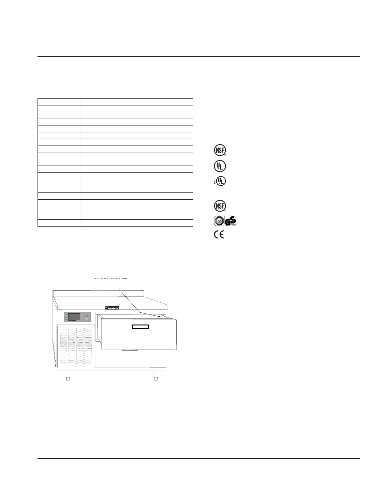
Serial Number Location
The serial number is located on the data plate mounted
inside of Drawer 1.
Always have the serial number of your unit available
when calling for parts or service.
Warranty Information
• Register your product for warranty,
• Verify warranty information,
• View and download a copy of your warranty,
@ www.delfield.com/warranty
Regulatory Certifications
115 Volt models are certified by:
•
•
•
230-240 Volt models are certified by:
•
• Technical Inspection Association
• European Conformity
National Sanitation Foundation (NSF)
Underwriters Laboratories (UL)
Underwriters Laboratories of Canada (CUL)
National Sanitation Foundation (NSF)
Serial Number Location
Part Number 9291505 10/16 5

General Information Section 1
THIS PAGE INTENTIONALLY LEFT BLANK
6 Part Number 9291505 10/16
Section 2
Installation
DANGER
Installation must comply with all applicable fire and
health codes in your jurisdiction.
DANGER
Use appropriate safety equipment during installation
and servicing
Warning
n
Remove all removable panels before lifting and
installing.
Warning
n
Do not damage the refrigeration circuit when installing,
maintaining or servicing the unit.
Location
Warning
n
This equipment must be positioned so that the plug is
accessible unless other means for disconnection from
the power supply (e.g., circuit breaker or disconnect
switch) is provided.
The location selected for the equipment must meet the
following criteria. If any of these criteria are not met, select
another location.
• Units are intended for indoor use only.
• The location MUST be level, stable and capable of
supporting the weight of the equipment.
• The location MUST be free from and clear of
combustible materials.
• Equipment MUST be level both front to back and side to
side.
• Position the equipment so it will not tip or slide.
• Front casters MUST be locked once positioned.
• Recommended air temperature is 41° - 86°F (5° - 30°C).
• Proper air supply for ventilation is REQUIRED AND
CRITICAL for safe and efficient operation. Refer to
Clearance Requirements chart on page 8.
• Do not obstruct the flow of ventilation air. Make sure the
air vents of the equipment are not blocked.
• Do not install the equipment directly over a drain.
Steam rising up out of the drain will adversely affect
operation, air circulation, and damage electrical /
electronic components.
Warning
n
Adequate means must be provided to limit the
movement of this appliance without depending on or
transmitting stress to the electrical conduit or gas lines.
Warning
n
To avoid instability the installation area must be capable
of supporting the combined weight of the equipment
and product. Additionally the equipment must be level
side to side and front to back.
Warning
n
This equipment is intended for indoor use only. Do not
install or operate this equipment in outdoor areas.
Caution
,
Do not position the air intake vent near steam or heat
exhaust of another appliance. Direct exposure to
excessive amounts of steam in machine compartment
will result in control board failure.
Part Number 9291505 10/16 7
Installation Section 2
Weight of Equipment
Model Ship Weight
F17VD84 520lbs (236kg)
F17VD84-CE 520lbs (236kg)
F18VD50 520lbs (236kg)
F18VD50-CE 520lbs (236kg)
F18VD82 720lbs (327kg)
F18VD82-CE 720lbs (327kg)
F2984VDR 520lbs (236kg)
F2984VDR-CE 520lbs (236kg)
F2984VDL 520lbs (236kg)
F2984VDL-CE 520lbs (236kg)
18650VDR 520lbs (236kg)
18650VDR-CE 520lbs (236kg)
18650VDL 520lbs (236kg)
18650VDL-CE 520lbs (236kg)
18682VDR 720lbs (327kg)
18682VDR-CE 720lbs (327kg)
18682VDL 720lbs (327kg)
18682VDL-CE 720lbs (327kg)
Clearance Requirements
DANGER
Minimum clearance requirements are the same for
noncombustible locations as for combustible locations.
The flooring under the appliance must be made of a
noncombustible material.
DANGER
Risk of fire/shock. All minimum clearances must be
maintained. Do not obstruct vents or openings.
Front Louvers Side Louvers
24”(60cm) 24”(60cm)
• Keep the vents clean and free of obstruction.
• The factory installed legs or casters must be used and
not removed.
Dimensions
Each 32” (81cm) drawer is heavy duty full extension with (2)
12” x 20” (31cm x 51cm) pan capacity.
Model L D H
F17VD84
F17VD84-CE
F18VD50
F18VD50-CE
F18VD82
F18VD82-CE
F2984VDR
F2984VDR-CE
F2984VDL
F2984VDL-CE
18650VDR
18650VDR-CE
18650VDL
18650VDL-CE
18682VDR
18682VDR-CE
18682VDL
18682VDL-CE
84"
(213cm)
84"
(213cm)
50"
127.0cm
50"
127.0cm
82"
(208cm)
82"
(208cm)
84"
(213cm)
84"
(213cm)
84"
(213cm)
84"
(213cm)
50"
(127cm)
50"
(127cm)
50"
(127cm)
50"
(127cm)
82"
(208cm)
82"
(208cm)
82"
(208cm)
82"
(208cm)
31.5"
(80cm)
31.5"
(80cm)
31.5"
(80cm)
31.5"
(80cm)
31.5"
(80cm)
31.5"
(80cm)
31.5"
(80cm)
31.5"
(80cm)
31.5"
(80cm)
31.5"
(80cm)
31.5"
(80cm)
31.5"
(80cm)
31.5"
(80cm)
31.5"
(80cm)
31.5"
(80cm)
31.5"
(80cm)
31.5"
(80cm)
31.5"
(80cm)
36"
(91cm)
36"
(91cm)
36"
(91cm)
36"
(91cm)
36"
(91cm)
36"
(91cm)
26"
(66cm)
26"
(66cm)
26"
(66cm)
26"
(66cm)
34"
(86cm)
34"
(86cm)
34"
(86cm)
34"
(86cm)
34"
(86cm)
34"
(86cm)
34"
(86cm)
34"
(86cm)
# of
Drawers
2
2
2
2
4
4
2
2
2
2
2
2
2
2
4
4
4
4
8 Part Number 9291505 10/16
Section 2 Installation
Electrical Service
DANGER
Check all wiring connections, including factory
terminals, before operation. Connections can become
loose during shipment and installation.
Warning
n
This appliance must be grounded and all field wiring
must conform to all applicable local and national
codes. Refer to rating plate for proper voltage. It is the
responsibility of the end user to provide the disconnect
means to satisfy the authority having jurisdiction.
VOLTAGE
All electrical work, including wire routing and grounding,
must conform to local, state and national electrical codes.
The following precautions must be observed:
• The equipment must be grounded.
• A separate fuse/circuit breaker must be provided for
each unit.
• A qualified electrician must determine proper wire size
dependent upon location, materials used and length
of run (minimum circuit ampacity can be used to help
select the wire size).
• The maximum allowable voltage variation is ±10% of
the rated voltage at equipment start-up (when the
electrical load is highest).
• Check all green ground screws, cables and wire
connections to verify they are tight before start-up.
RATED AMPERAGES, HORSEPOWER, VOLTAGE &
POWER CORD CHART
A 7’ (2.1 m) long grounded supply cord with three-pronged
plug is provided with the standard units. Simply plug into a
three-pronged wall outlet for proper grounding of the unit
to begin operation.
When disconnecting the unit from the power source, do
not pull on the cord. Firmly grip the plug and remove from
outlet.
Model Amps HP Volts/Hertz/Phase Plug
F17VD84 6.0 1/3 115/60/1 5-15P
F17VD84-CE 3.6 1/3 230-240/50/1 BS1363
F18VD50 6.0 1/3 115/60/1 5-15P
F18VD50-CE 3.6 1/3 230-240/50/1 BS1363
F18VD82 12.0 (2) 1/3 115/60/1 5-15P
F18VD82-CE 7.2 (2) 1/3 230-240/50/1 BS1363
F2984VDR 6.0 1/3 115/60/1 5-15P
F2984VDR-CE 3.6 1/3 230-240/50/1 BS1363
F2984VDL 6.0 1/3 115/60/1 5-15P
F2984VDL-CE 3.6 1/3 230-240/50/1 BS1363
18650VDR 6.0 1/3 115/60/1 5-15P
18650VDR-CE 3.6 1/3 230-240/50/1 BS1363
18650VDL 6.0 1/3 115/60/1 5-15P
18650VDL-CE 3.6 1/3 230-240/50/1 BS1363
18682VDR 12.0 (2) 1/3 115/60/1 5-15P
18682VDR-CE 7.2 (2) 1/3 230-240/50/1 BS1363
18682VDL 12.0 (2) 1/3 115/60/1 5-15P
18682VDL-CE 7.2 (2) 1/3 230-240/50/1 BS1363
Part Number 9291505 10/16 9
Installation Section 2
Screws
Drain Connections
Warning
n
If a refrigerated base does not have a condensate
evaporator supplied, you must connect the condensate
line to a suitable drain. Otherwise, water will collect on
the floor, causing a potentially hazardous situation.
Warning
n
Moisture collecting from improper drainage can create a
slippery surface on the floor and a hazard to employees.
It is the owner’s responsibility to provide a container or
outlet for drainage.
All models are standard with a condensate evaporator pan.
Refrigeration
The refrigeration system uses HFC-404A refrigerant.
If your freezer seems to vibrate excessively when the
compressor is running, loosen (but do not remove) the
bolts on the compressor. Semi hermetic models should be
loosened before operating.
Model
F17VD84 Left 30 oz (850.5g)
F17VD84-CE Left 30 oz (850.5g)
F18VD50 Left 30 oz (850.5g)
F18VD50-CE Left 30 oz (850.5g)
F18VD82 Left (2) 30 oz (850.5g)
F18VD82-CE Left (2) 30 oz (850.5g)
F2984VDR Right 30 oz (850.5g)
F2984VDR-CE Right 30 oz (850.5g)
F2984VDL Left 30 oz (850.5g)
F2984VDL-CE Left 30 oz (850.5g)
18650VDR Right 30 oz (850.5g)
18650VDR-CE Right 30 oz (850.5g)
18650VDL Left 30 oz (850.5g)
18650VDL-CE Left 30 oz (850.5g)
18682VDR Right (2) 30 oz (850.5g)
18682VDR-CE Right (2) 30 oz (850.5g)
18682VDL Left (2) 30 oz (850.5g)
18682VDL-CE Left (2) 30 oz (850.5g)
Compressor
Position
Ref. Charge
Casters Or Legs
DANGER
Legs or casters must be installed and the legs or casters
must be screwed in completely to prevent bending.
When casters are installed the mass of this unit will
allow it to move uncontrolled on an inclined surface.
These units must be tethered/secured to comply with
all applicable codes.
Warning
n
Use a jack to lift the refrigeration unit off the ground
just far enough to remove the leg/caster. Place blocking
underneath the unit. Do not work underneath a raised
unit without proper blocking. Do not lift the unit more
than necessary to remove the leg/caster. Lifting the unit
too far can make the unit unstable.
LEG LEVELING
All four 6” (15cm) legs are adjustable. Adjust each leg
until the unit is stable and level left to right. If necessary
adjusting the front legs slightly higher than the rear by
about 1/8” (3mm) will help the door remain closed.
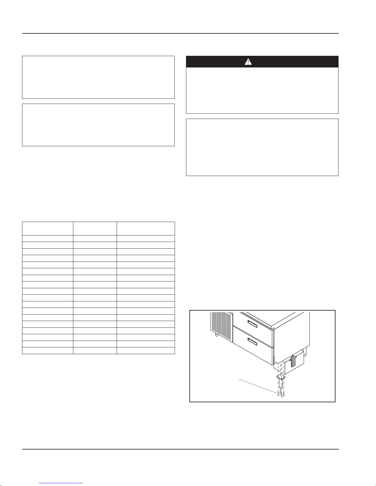
LEG REMOVAL AND REPLACEMENT
1. Place a jack underneath the refrigeration unit as close
as possible to the leg. Lift the unit just high enough to
remove the leg from underneath the refrigeration unit.
Place blocking underneath the unit to prevent the unit
from falling during removal of the leg.
2. Remove four screws from the upper portion of the leg.
3. Remove the leg from the refrigeration unit.
4. Reverse the above steps to install a replacement leg.
10 Part Number 9291505 10/16
Leg Replacement
Section 2 Installation
Screws
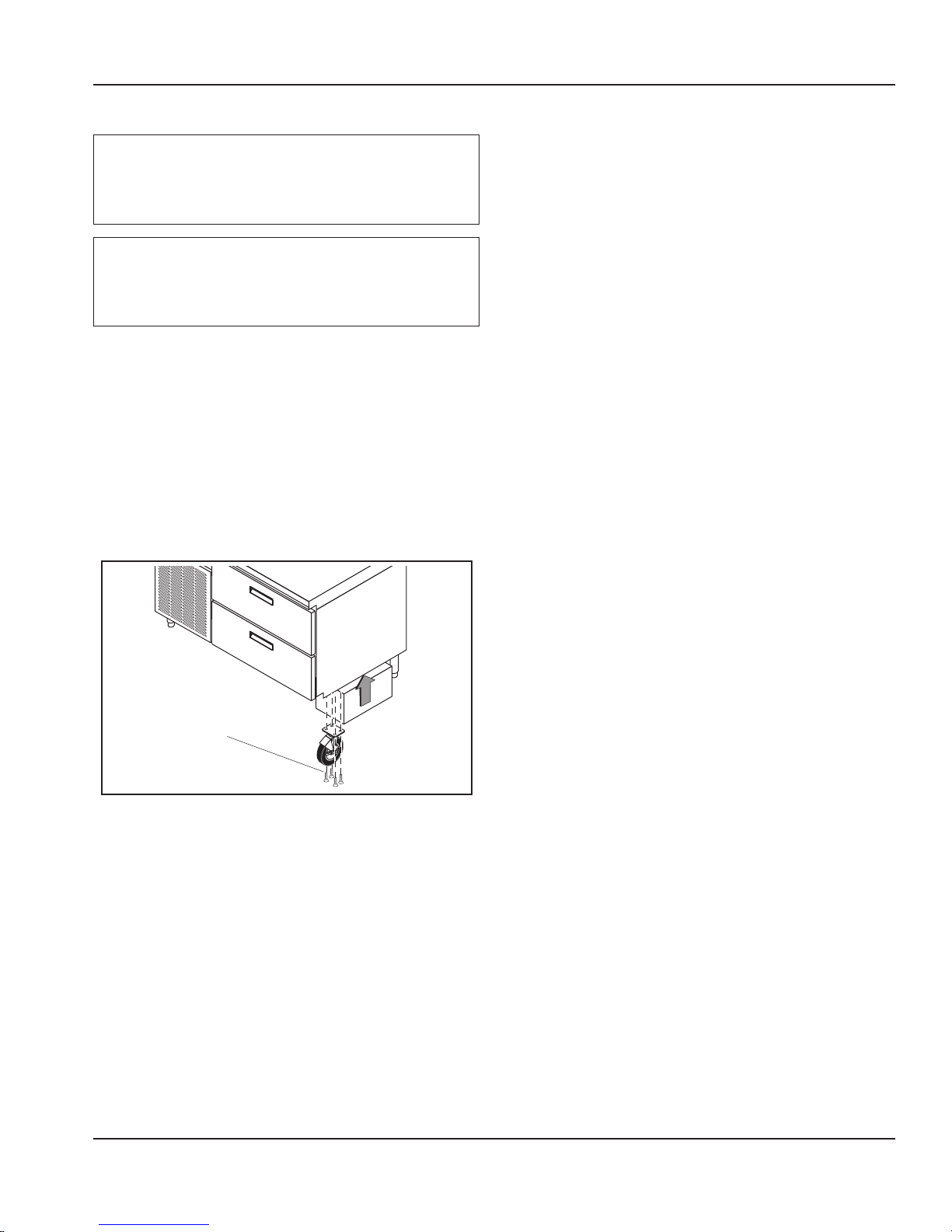
CASTER REMOVAL AND REPLACEMENT
Warning
n
The unit must be installed in a stable condition with
the front wheels locked. Locking the front casters after
installation is the owner’s and operator’s responsibility.
Caution
,
After installing casters, the unit must stand upright for
twenty-four (24) hours before being powered up to
assure oil return to the compressor sump.
1. Place a jack underneath the refrigeration unit as close
as possible to the caster. Lift the unit up just high
enough to remove the caster from underneath the
refrigeration unit. Place blocking underneath the unit
to prevent the unit from falling during removal of the
caster.
2. Remove four screws from the upper portion of the
caster.
3. Remove the caster from the refrigeration unit.
4. Reverse the above steps to install a replacement caster.
Caster Replacement
Part Number 9291505 10/16 11

Installation Section 2
THIS PAGE INTENTIONALLY LEFT BLANK
12 Part Number 9291505 10/16

Section 3
Operation
DANGER
The on-site supervisor is responsible for ensuring that
operators are made aware of the inherent dangers of
operating this equipment.
Caution
,
Do not throw items into the storage area. Failure to
heed this recommendation could result in damage to
the interior of the cabinet or to the blower coil.
DANGER
Do not operate any appliance with a damaged cord
or plug. All repairs must be performed by a qualified
service company.
DANGER
Never stand on the unit or in its drawers! They are
not designed to hold the weight of an adult, and may
collapse or tip if misused in this manner.
Warning
n
Do not contact moving parts.
Warning
n
All covers and access panels must be in place and
properly secured, before operating this equipment.
Warning
n
Do not use electrical appliances inside the food storage
compartment of this appliance.
Warning
n
The operator of this equipment is solely responsible
for ensuring safe holding temperature levels for all
food items. Failure to do so could result in unsafe food
products for customers.
General
Do not pack drawer so full that air cannot circulate. Load
product level with top of pans and keep all food covered.
Each drawer operates independently in one of four modes
at any time.
Refrigerator Mode
The drawer operates at a set point of 37°F (3°C), maintaining
a range between 34°F (1°C) and 40°F (4°C).
Freezer Mode
The drawer operates at a set point of -3°F (-19°C),
maintaining a range between -6°F (-21°C) and 0°F (-17°C).
Thaw Cabinet Mode
The drawer maintains temperature between 36°F (2°C) and
41°F (5°C) for a minimum of 4 hours or longer if required.
Once the thaw cycle is complete, the drawer mode is
automatically changed to refrigerator mode.
Convenience Chiller Mode
The drawer operates as a chiller, maintaining the
convenience chiller set point of 23˚F (-5˚C) for four hours.
Once the convenience chiller cycle is complete, the drawer
mode is changed to refrigerator mode.
Warning
n
Damp or wet hands may stick to cold surfaces.
Caution
,
Do not block the supply and return air grills or the air
space around the air grills. Keep plastic wrappings,
paper, labels, etc. from being airborne and lodging in
the grills. Failure to keep the air grills clear will result in
unsatisfactory operation of the system.
Part Number 9291505 10/16 13

Operation Section 3
Refrigeration System
In a 2-drawer system there is a single compressor. In a
4-drawer system there are two compressors; one operating
drawers 1 and 2 and one operating drawers 3 and 4.
Temperature sensors are located in each drawer. The drawer
temperatures are displayed on the control panel.
An automatic defrost occurs every six hours in refrigerator
and freezer mode.
Chill Time
• These times are based on chilling at a cabinet
temperature of 5˚F(-15˚C) and 10 pounds(4.5kg) of
product per drawer.
• The times are based on the duration to go from
140˚F(60˚C) to 40˚F(4˚C).
• The maximum limit of product to be chilled is no more
than 10 pounds(4.5kg), not including pans.
• Product should be covered and no more than 2”(5cm)
deep in the pan.
Product Chill Time
Green Beans 2 hour 49 minutes
Mash Potatoes 3 hours 21 minutes
Scrambled Eggs 1 hour 53 minutes
Soup (Vegetable) 2 hour 58
Spaghetti with Meat sauce 2 hours 32 minutes
Control Panel
The control panel provides information indicating the
current mode of each individual drawer. In addition, the
actual temperature of the drawer is displayed.
All operating functions are accessible on the Versa Drawer
control panel. Operators can select the drawer modes
or activate the manual defrost. Access to all diagnostic
functions require a qualified service technician.
2-Drawer Interface Control
4-Drawer Interface Control
Control Function
3
1
4
2
Buttons are located next to the drawer display
on the Control Panel. The drawer select buttons
select the drawer to be configured.
These arrows are used to change a drawer to
operate in a desired mode, refrigerate, freezer,
thaw or chill.
Used to back up to the previous step.
The i button is used to initiate the manual
defrost mode.
14 Part Number 9291505 10/16
Section 3 Operation
Setting The Drawer Mode
1. Press the button # next to the drawer display to be
changed.
NOTE: Current drawer mode text size will decrease.
2. Press the up or down arrow to select between
refrigerate, freeze, chill or thaw until desired mode is
reached.
3. Press the drawer display # button again to lock the
desired mode setting.
NOTE: Text size will return to original size.
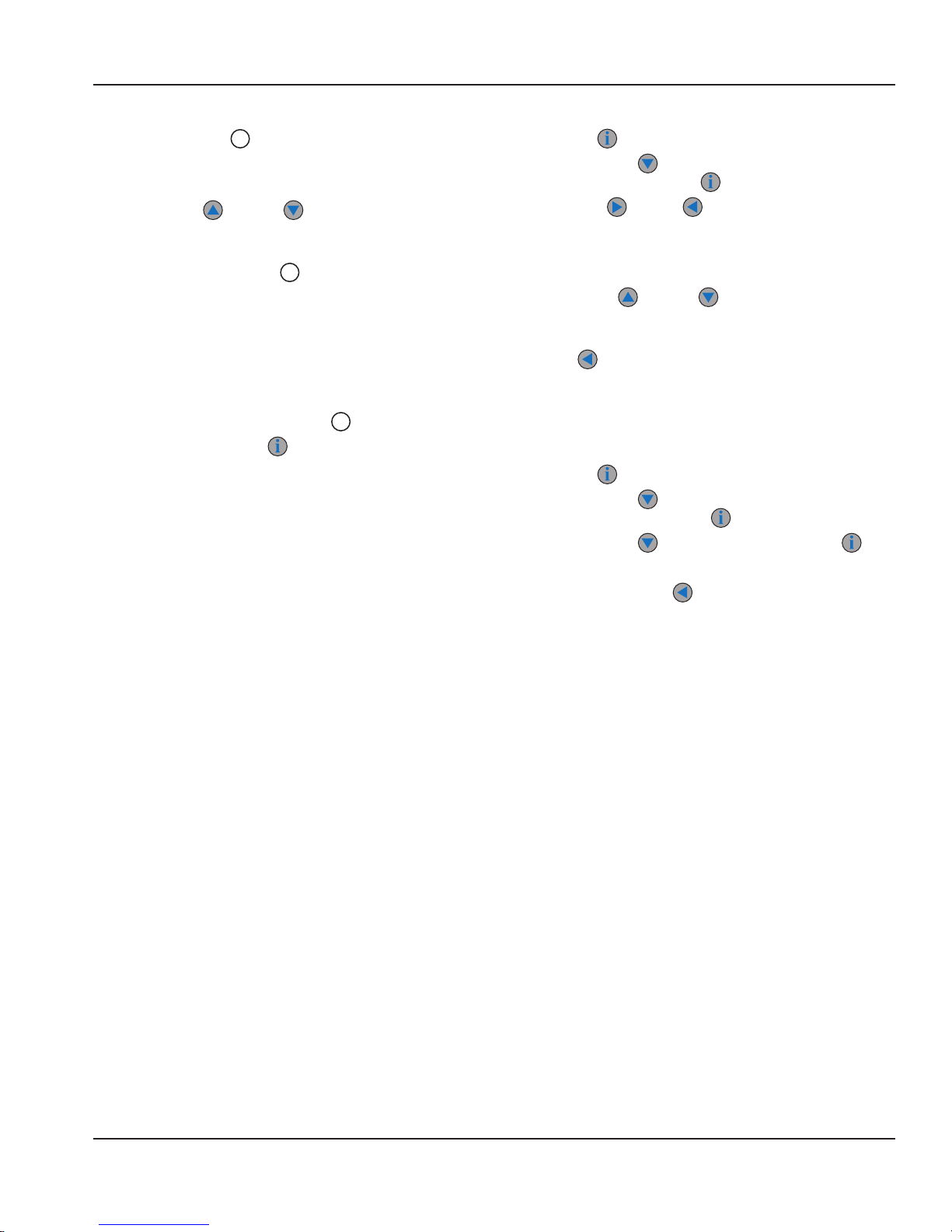
Activating Manual Defrost
NOTE: These steps must be performed within 1 second.
1. Press the desired drawer display # button.
2. Immediately press the button.
Setting the Clock
1. Press the button until “Program Menu” appears.
2. Press the down arrow until brackets are around
“Time & Date”, then press .
3. Press right and left arrows to get to parameter
to be adjusted.
NOTE: The caret symbol [^] under the text indicates the
parameter to be adjusted.
4. Press the up or down arrows to adjust
parameter.
5. Once correct time and date are set press the back
or left button twice to return to the main display
screen. If no action is taken for 30 seconds the control
will automatically return to main display screen.
Fahrenheit to Celsius
1. Press the button until “Service Menu” appears.
2. Press the down arrow until brackets are around
“Configuration”, then press .
3. Press the down arrow to “System” and press .
4. In this menu will be “Metric”, change to Yes.
5. Press the back or left arrow until back to main
menu.
Part Number 9291505 10/16 15

Operation Section 3
THIS PAGE INTENTIONALLY LEFT BLANK
16 Part Number 9291505 10/16
 Loading...