

Page 1
Defi-Link VSD X
Operation Manual
DF05704
Defi-Link VSD X is a product to display vehicle information such as speed and engine speed on the Target Screen(the
exclusive reflecting plate). When installing and operating this product, be sure to read the cautionary items of this
operation manual as well as those given in the operation manual for the vehicle in which this display will be installed.
Obtain a full understanding of the cautionary items and use the product accordingly.
In the event that this product (or the vehicle in which it is installed) is lent to or transferred to another person, please be
sure this operation manual accompanies the product.
http://www.defi-shop.com/
'07.01-1
Before Installation(for installation personnel)
In this manual, the degree of hazard arising from actions such as improper operation is separated into the 3 levels “Danger,”
“Warning,” and “Caution.” In addition, instructions that must be followed for safe and proper use of this product as well as
practices that must be maintained are marked with a “Confirmation” heading. Please read and become familiar with these
sections.
Danger
Warning
Caution
Confirmation
●Ensure that the vehicle will remain stationary and turn off the engine before installing this product. Failure to do so could
result in a fire, and could make the vehicle move during installation.
●Remove the key from the ignition and disconnect the negative (-) battery terminal prior to installation of this product.
Failure to do so could result in a fire caused by an electrical short circuit.
●Take care n ot to install this product in a way that interferes with safety equipment such as seat belts and air
bag systems or vehicle operation equipment such as engine controls, steering wheel or brake systems.
Interference with normal operation of the veh icle can result in a n accident or fire.
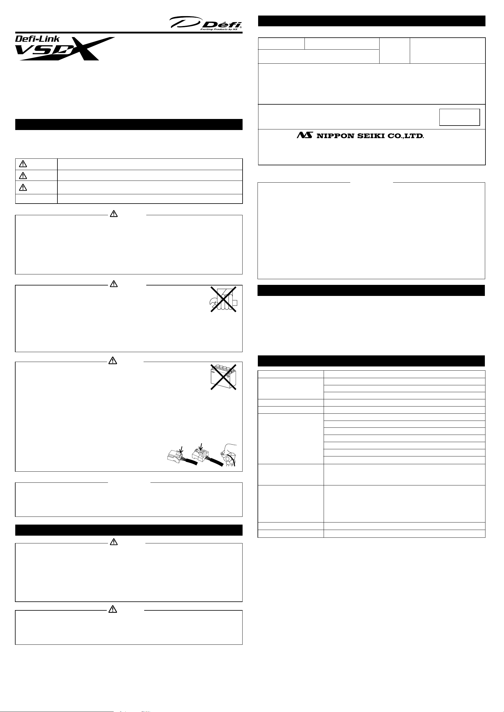
●Solder or use a solderless connector for wiring connections and make sure connections are insulated. In
areas where there could be tension or sudden impacts on the wiring, safegua rd the wiring with corrugated
tubing or other shock abso rbent material. Accidental shorts can cause fires.
Indicates the imminent dangerous situation of death or serious injury if the product is mishandled.
Indicates the possibility of death or serious injury if the product is mishandled.
Indicates a conceivable source of personal injury or damage to equipment if the product is
improperly operated.
Indicates an instruction that must be performed or practice that must be maintained.
Danger
Warranty
* Refer to Terms and Conditions
Product Name
Customer:
Name
Address
Warranty Period
Date of purchase
Defi Business Division
Ueno DK Bldg 8F, 15-4 Ueno 1-Chome, Taitou-ku, Tokyo 110-0005 JAPAN
E-mail: defishop@nippon-seiki.co.jp
URL: http://www.defi-shop.com/
●The vehicle information other than speed and engine speed is not displayed unless this product is connected to
Defi-Link System.
●The speedometer and the tachometer of this product are for reference purposes only. Please drive according to the
indication of vehicle's originally equipped instruments.
●When this product is linked to the Defi-Link System, connect the LINK connector of the D.C.Unit and the METER
OUTPUT1 connector of the Defi-Link Control Unit II Version 2.0 or the Defi-Link Control Unit II (or the METER
connector of the Defi-Link Control Unit) with the meter wire. Misconnection could damage the product.
●When this product is linked to the Defi-Link system, the tachometer signal must be input to the Defi-Link Control
Unit II(or the Defi-Link Control Unit). Set the number of cylinders of the Defi-Link Control Unit II(or the Defi-Link
Control Unit). Do not connect the Tacho Signal Wire(blue wire) from the D.C.Unit.
●This product can be used only on 1, 2, 3, 4, 5, 6, and 8 cylinder vehicles with 4 cycle engine. However, it cannot be
used on 1 and 2 cylinder vehicles under some circumstances. Refer to the Product Specifications. Engine
revolution signal of diesel vehicles cannot be displayed.
●Data on boost and intake manifold pressure cannot be displayed.
●When this product is linked to the Defi-Link System, be sure to follow the instructions for the Defi-Link Control Unit
II(or the Defi-Link Control Unit).
●The switch illumination of the D.C.Unit is interlocked with turning on/off the ignition of the vehicle.
DF05704
• • 〜
Lot. No.
1 year
CUT HERE
Confirmation
●Carefully consider the installation location and driver's operation of the product before
installation. Do not install the product where it interrupts driving and the safety deices of vehicle.
Be sure not to install the unit where it could fall. Improper installation or operation could cause
the product to fall and damage the vehicle or cause serious danger by impeding driving.
●Do not disassemble or modify this product. Such actions can not only damage or destroy the
product but will also void the warranty.
●Do not perform installation of this product immediately after the engine has been switched off.
The engine and exhaust system are extremely hot at this time and can cause burns if touched.
●Ensure that the wiring of this product does not have an adverse impact on the other wiring of the vehicle. Any
controlling devices or other electronic components of the vehicle could be damaged.
●Please keep children and infants away from the installation area. Children may swallow small parts or be injured in
other ways.
disassemble/
modify
Caution
Warning
●This product is designed for use on 12V vehicles. Do not install this product on vehicles with 24V
systems.
●Insulate any unused wires. If any wires or connectors loosen during installation, please make
sure they are correctly reattached.
●Dropping any of the components of this product will result in damage to the product.
●Excessive force on switches/terminals may result in damage to the product.
●Use only the wires provided. If additional wires are required, use the same of quality and gauge wire as is provided
with the kit.
●Do not attach wires on the body of the vehicle or engine parts as this may result in damage to the product.
●Install sensors away from heat and moisture to avoid damage.
●Install sensors away from ignition and also radio signal frequency interference as this could cause the gauges to
malfunction.
●Do not wire the sensor wires near the engine, exhaust pipe or turbine. It may result in damage or fusion of wires.
●Do not expose D.C.Unit to moisture, dust or direct sunlight. Do not place product directly in front of heat vents.
●Wear gloves to avoid burns when soldering and cuts when working with wiring.
●Make sure the waterproof processing is done when diverging wires in the
engine compartment.
●Do not pull the wires out of connectors forcefully. The connectors may be
broken and the wires may be cut. When pulling out the wires, press the
lock firmly and unclip the locks of connectors.
24V
Confirmation
●Be sure to follow all instructions in this manual to ensure safe installation and operation of the product.
●When the negative (-) battery terminal is disconnected, equipment such as clocks and audio components having
internal memory may lose their memory data. Follow the operation manual of each component to reset data after
installation of this product.
●After installation is complete, return this operation manual and the package to the customer along with the warranty.
About Installation and Operation(for customer and installation personnel)
Warning
●Please have this product installed by the retail store or dealer where it was purchased. Installation by the customer
will void the warranty.
●Do not disassemble or modify this product. Such actions can not only damage or destroy the product but will also
void the warranty. This product is high-voltage, and there is an possible to get an electric shock.
●In order to ensure safe driving, check the information on this display only for short periods of time. Looking at the
display for long periods of time could distract adequate attention from the road and result in an accident.
●Discontinue use of this product if nothing is displayed, water gets into the unit, or smoke or a strange odor comes
from the unit. If such a condition occurs, contact the sales outlet or installation personnel as soon as possible.
Continued use while the condition exists could result in an accident or fire.
●Do not operate during driving.
Main Features(for customer)
●The display is high Visibility by adopting the exclusive target screen(the new VSD technology) and super high bright
blue-green VFD
●The brightness is adjusted automatically. (The sensor is included in the product.)
●Two super high bright LED indicators
●The structure of the new mounting bracket allows angle adjustment freely.
●Displays speedometer and engine speed. By connecting to the Defi-Link System, various information is displayed.
●The tachometer can operate with hybrid vehicles and rev limited vehicles by cutting the ignition. (Only if the product
is used without linking to the Defi-Link System or used with linking to the Defi-Link Control Unit II Version 2.0.)
●The switch illumination of the D.C.Unit is interlocked with turning on/off the ignition of the vehicle.
Product Specifications(for customer and installation personnel)
Power Supply Voltage
Current Consumption
Operational Temperature Range
Storage Temperature Range
Display Range
Applicable Speed Pulse
Applicable Number of Cylinders
Dimensions
Gross Weight
DC10V to 15V(For 12V vehicles)
+B line
IGN line
ILM line
MAX 1A only while the closing mode is displayed. (Dark current 0mA)
MAX 1A
MAX 0.1A
−20 to +60℃, −4 to +140゜F (under 80% relative humidity)
−40 to +80℃, −40 to +176゜F (under 80% relative humidity)
Speedometer(SP)
Engine speed(TA)
Oil temperature(O.TEMP.)
Water temperature(W. TEMP.)
Oil pressure(OIL P.)
Fuel pressure(FUEL P.)
Exhaust temperature(EXT. T.)
0〜400km/h(0〜240MPH)
0〜9,500rpm
51〜150℃(123〜302゜F)
21〜120℃(69〜248゜F)
0〜1,000kPa(0〜145PSI)
0〜600kPa(0〜87PSI)
210〜1,100℃(400〜2,010゜F)
A) 2・4・8・16(mainly for Japanese vehicles)
B) Free pulse setting(1,274 pulse/km〜16,562 pulse/km
2,051 pulse/mile〜26,665 pulse/mile)
Without linking: 1・2・3・4・5・6・8 (Set up with D.C.Unit.)
If connected to the Defi-Link Control Unit II Version 2.0(DF05002): 1・2・3・4・5・6・8[※]
If connected to the Defi-Link Control Unit II(DF05001): 3・4・5・6・8[※]
If connected to the Defi-Link Control Unit(DF01301): 3・4・5・6・8[※]
[※ Set up with each control unit.]
Refer to page 2.
820g, 1.8lb(including display unit, D.C.Unit, wires, package)
Caution
●On no event will Nippon Seiki Co., Ltd. be liable to you for any damages arising out of the use or inability to use the
product, even if Nippon Seiki Co., Ltd. has been advised of the possibility of such damage.
●Do not pull the wires out of connectors forcefully. The connectors may be broken and the wires may be cut. When
pulling out the wires, press the lock firmly and unclip the locks of connectors.
●Do not take off the rubber covering round the target screen. The plate is sharp-edged.
-1-
Page 2
Replacement Parts(for customer)
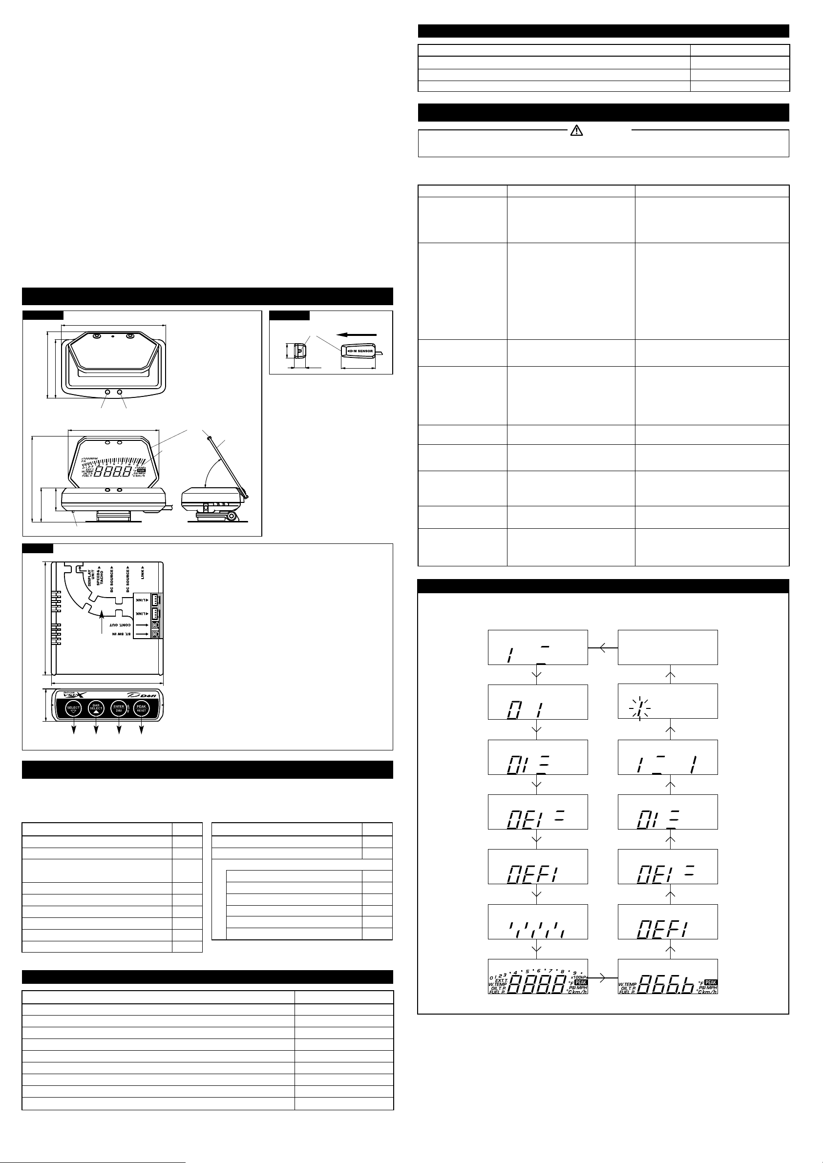
Part Names and Dimensions in inches(mm)
Display Unit
2 1/2 (63.2)
2 13/16 (71.9)
Indicator(green LED) Indicator(red LED)
3 5/8 (92.3)
15/16
(24.5)
1 7/16 (36.7)
D.C.Unit
13/16 (96.8)
4 7/16 (112)
3 13/16 (97.3)
Connector for the DIM Sensor(Black)
⑤ ⑥ ⑦ ⑧ ⑨
⑭
3 3/4 (95.6)
Rubber for Target Screen
Display
Position
⑩
⑪
⑫
⑬
Target
Screen
°
58
①
SELECT/▽DOWN SWITCH
②
BAR SELECT/▲UP SWITCH
③
ENTER/DIM/SET UP SWITCH
④
PEAK/RESET SWITCH
⑤
For Display unit
⑥
For Speed & Tacho signal wire(White)
⑦
For Power supply wire / Power supply link wire(White)
⑧
For Power supply wire / Power supply link wire(White)
⑨
For Control Unit II / Control Unit / Gauge / Display(White)
⑩
For Control Unit II / Control Unit / Gauge / Display(White)
⑪
For Control Unit II / Control Unit / Gauge / Display(White)
⑫
For Control output(Red)
⑬
Unused(Black)
⑭
Storage space for wires ⑩ through ⑬
Wires connected to ⑩ through ⑬ can be fit in the place neatly.
DIM Sensor
Sensing part
9/16
(14.4)
7/16 (11.2)
Driving direction
1 5/16 (33)
Item
Part Number
Fuse for Power Supply Wire(4A) 2pcs PDF05005G
Rubber for Target Screen
Mounting Bracket set [※2 Refer to the Parts List for the contents]
PDF05711G
PDF05712G
Trouble Shooting(for customer and installation personnel)
●If operation of the product seems unusual, inspect the product to confirm that there is no malfunction. If an
operational problem has occurred, it could result in an accident.
※In addition to a general inspection of the product, use the following table to confirm proper operation of the unit. If the
operational problem does not appear in the following table, contact the installation personnel.
Phenomenon Possible Cause Corrective Action
○Does not display.
○The gauge doesn't perform
the opening and the closing
mode. Power is not
supplied.
○The engine speed is not
displayed correctly.
○The speed is not displayed
correctly.
○The auto dimmer mode is
on, but the display is dark
or the brightness of the
display doesn't change.
○Does not carry out the
closing mode.
○The product is connected to
the Defi-Link System, but
the speed is not recorded.
illumination is not
interlocked with switching of
the vehicle illumination.
○The display is dark. ○Adjust the angle of the display referring to How to
○The information on the
display is not the same as
that on the originally
equipped gauges.
○Wiring of the power supply wire or the
display wire is improper.
○The fuse is blown out.
○The locks of the solderless connectors
are not locked tightly.
○Wiring of the tachometer signal wire is
wrong.
○Setting of the number of cylinders is
wrong(D.C.Unit/Defi-Link Control Unit
II/Defi-Link Control Unit).
○LINK of D.C.Unit and METER OUTPUT2
of Defi-Link Control Unit II are connected.
○The tachometer signal wire is not
connected to Defi-Link Control Unit II or
Defi-Link Control Unit (in the case that
the product is connected to the Defi-Link
System).
○Wiring of the speed signal wire is
wrong.
○Setting of the speed pulse is wrong.
○The DIM sensor is not connected.
○The front of the DIM sensor is
obstructed.
○The manual dimmer mode is selected in
the setting of the illumination control.
○The direction of the DIM sensor is
wrong.
○The wiring of the red line of the power
supply wire is wrong.
○The REC button is pressed when the
vehicle is stationary.
○The condition is normal.○Switching of the unit
○The angle of the display unit is not
proper.
○The setting of the speed pulse or the
number of cylinders is wrong.
Pop Demo of Special DisplayPop Demo of Special Display
When the Pop demo is selected for the special display, the following demo is played.
Refer to Operation / ⑤Setting of Special Display.
Warning
○Check wiring as per instructions in this manual.
○Make sure the wiring is not touched on the
vehicle body and then change the fuse.
○Check the lock of the solderless connectors.
○Check wiring as per instructions in this manual.
○Check the number of cylinders as per instructions
in this manual and the manuals of the Defi-Link
Control Unit II or the Defi-Link Control Unit.
○Connect the LINK connector of the D.C.Unit and
the METER OUTPUT1 connector of the Defi-Link
Control Unit II using the meter wire.
○Connect the tachometer signal wire to the Defi-
Link Control Unit II(or the Defi-Link Control Unit).
○Check wiring as per instructions in this manual.
○Check the speed pulse as per instructions in this
manual.
○Connect the DIM sensor as per instructions in this
manual.
○Attach the DIM sensor in a position without any
obstruction which interrupts the front of the sensor.
○Reset the illumination control setting as per
instructions in this manual.
○Check wiring as per instructions in this manual.
○Press the REC button when the vehicle is moving.
○Switching of D.C.Unit illumination is interlocked
with turning on/off the ignition.
install / Step3 / ②The angle of the display.
○Recheck the setting and setup again. When the
setting is not wrong, it depends on the margin of
error. Drive according to the indication of
originally equipped gauges.
1 1/16 (27.5)
① ② ③ ④
Parts List(for customer and installation personnel)
The following parts are included with this product. Confirm that all parts are present before installing the product. In
addition, these parts are sold separately for part replacement. Contact your retailer for further information.
NOTE: A Japanese operation manual, a wiring manual, and a questionnaire card are included other than the parts
listed below. They are effective only in Japan.
Part Name
Display unit(wire 8 1/3ft, 2.5m) 1
D.C.Unit(Exclusive Control Unit)
Speed & Tacho Signal Wire
(Green SP, Blue TA) 6 2/3ft, 2m
Tachometer Signal Wire(Blue) 6 2/3ft, 2m [※1]
DIM Sensor(wire 6in, 0.15m)
Power Supply Wire 2 3/2ft, 0.8m
Meter Wire 10in, 0.25m [※1]
Power Supply Link Wire 10in, 0.25m [※1]
Control Out Wire(pink) 3 1/3ft, 1m [※1]
[※1 Use only when connected to the Defi-Link system]
Optional Parts(for customer)
Item
Defi-Link Control Unit II Version 2.0
Defi-Link Oil Pressure Sensor Set(Sensor thread size: 1/8PT)
Defi-Link Fuel Pressure Sensor Set(Sensor thread size: 1/8PT)
Defi-Link Oil Temperature Sensor Set(Sensor thread size: 1/8PT)
Defi-Link Water Temperature Sensor Set Sensor thread size: 1/8PT)
Defi-Link Exhaust Temperature Sensor Set(Sensor thread size: 1/8PT)
Oil/Water Temp. Sensor(Sensor thread size: 1/8NPT) PDF03905S
1/8 NPT/PT Conversion Socket for pressure sensor
1/8 NPT fitting for Exhaust Temp. Sensor
Quantity
1
1
1
1
1
1
1
1
Part Name
Operation manual
Terms and Conditions
Mounting Bracket Set [※2]
Double-sided tape
M4 Bolt, Nut, Washer
Tapping screw(for Mounting Bracket)
Mounting Bracket
Clamp
Solderless connector
PDF00713SS
PDF00806SS
PDF00908SS
PDF01006SS
PDF01114SS
Quantity
1each
Part Number
DF05002
PDF00708G
PDF01109G
1
1
2
2
1
4
6
-2-
Page 3

■The following contents are classified into 3 categories. Please read the
necessary instructions and directions for use according to your situation as
follows:
【When the Defi-Link VSD X is used WITHOUT linking it to the Defi-Link System (W/O Linking)】
W/O LinkingW/O Linking
【When the Defi-Link VSD X is used WITH linking it to the Defi-Link System (W/ Linking)】
W/ LinkingW/ Linking
【Instructions which should be read in each case (Common)】
W/O LinkingW/O Linking
CommonCommon
W/ LinkingW/ Linking
■In the parts saying "Defi-Link Control Unit II," it applies to both the Defi-Link
Control Unit II(DF05001) and the Defi-Link Control Unit II Version 2.0(DF05002)
as long as any other special notes have not been described.
Installation (for installation personnel)
W/ LinkingW/ Linking
【Defi-Link VSD X and Defi-Link System wiring diagram
(When the Defi-Link VSD X is used WITH linking it to the Defi-Link System)】
※These procedures are applicable on condition that Defi-Link Control Unit II(or Defi-Link Control Unit) and the
power supply wire have been installed. If the Defi-Link VSD X and the Defi-Link System are installed at the same
time, install the Defi-Link Control Unit II first by referring to the operation manual.
Tachometer signal wire(blue wire)
Sensor wires
→to each sensors or vehicle
Connect Defi-Link Meter BF to
METER OUTPUT2
(Defi-Link Display is connectable)
Vehicle
(ECU, etc.)
Green wire(speed signal)
Speed & Tacho signal wire
※Do not connect the blue
wire(tacho signal)
Power supply link wire(Connect DC SOURCEs mutually)
Meter Wire(Connect METER OUTPUT1 and LINK)
※Do not connect OUTPUT2 and LINK.
Power supply wire
Blue wire(tacho signal)
.
W/O LinkingW/O Linking
CommonCommon
W/ LinkingW/ Linking
Warning
●Carefully read the "Before Installation" and "About Installation and Operation" sections of the manual concerning installation
and operation. Then install the product properly and safely. Installation in an unsuitable location or improper installation can
result in the product falling from its position or damage to the vehicle.
Caution
●When installing the display, be sure to follow the instructions of the Defi-Link Control Unit II(or the Defi-Link Control Unit).
●Do not pull the wires out of connectors forcefully. The
connectors may be broken and the wires may be cut.
When pulling out the wires, press the lock firmly and
unclip the locks of connectors.
STEP1 Wiring power supply wire and signals
W/O LinkingW/O Linking
How to branch signal wire using solderless connector
wire from the vehicle
Insert wire of attached parts.
Press until a clicking sound is heard.
Speed & tacho signal wire(6 3/5ft, 2m)【Figure2】 Tachometer signal wire(4 3/5ft, 2m)
Blue:Tacho signal
Engine control unit(ECU) or ignition primary coil
Green:Speed signal
※When connected to the Defi-Link System, do
not connect the blue wire - insulate it.
2Pins
CommonCommon
【Figure1】 Power supply wire(2 3/5ft, 80cm)
Fuse 4A
5Pins(1pin is vacant.)
【Figure3】
Red:Battery(To 12V battery wire)
Orange:IGN(To 12V wire when ignition is on)
Black:GND(To ground, negative battery terminal)
White:+ILM(To 12V wire when small light is on)
※When this product is used without a connection to the
Defi-Link System, it is not necessary to connect the
white wire - insulate it.
※Use this wire only When Defi-Link VSD X is used
WITH linking to the Defi-Link System
Blue:Tacho signal
Engine control unit(ECU) or ignition primary coil
2Pins(1Pin is vacant.)
Connect to the Defi-Link Control Unit II(or Defi-Link
Control Unit)
※Do not connect to D.C.Unit.
W/O LinkingW/O Linking
【Defi-Link VSD X wiring diagram
(When the Defi-Link VSD X is used WITHOUT linking it to the Defi-Link System)】
W/ LinkingW/ Linking
Vehicle
(ECU, etc.)
DIM
Defi-Link Control Unit II
(or Defi-Link Control Unit)
Sensor
Defi-Link VSD X
Display unit
Display unit's wire
Defi-Link VSD X
D.C.Unit
Connect Defi-Link
Meter to LINK
(Defi-Link Display is
connectable.)
1) Disconnect the previously connected power supply wire from the Defi-Link Control Unit II(or the Defi-Link Control Unit).
2) Connect the disconnected power supply wire to the DC SOURCE
※
There are two DC SOURCE connectors. Both connectors are usable.
3) Connect the DC SOURCE
connectors
of the Defi-Link Control Unit II(or the Defi-Link Control Unit) and the D.C.Unit
connector
of the D.C.Unit.
using the attached power supply link wire.
4) In the case where a meter wire is already connected to the METER OUTPUT1
II(or the METER
connector
of the Defi-Link Control Unit), disconnect the meter wire. (If the METER OUTPUT1
connector
of the Defi-Link Control Unit
connector of the Defi-Link Control Unit II is not in use, skip the next procedure and go to 6.)
5) Connect the disconnected meter wire to the LINK
connector
of the D.C.Unit.
※There are three LINK connectors. All three connectors are usable.
6) Connect the METER OUTPUT1
the attached meter wire. (Connect the METER
connector
of the Defi-Link Control Unit II and the LINK
connector
of the Defi-Link Control Unit and the LINK
connector
of the D.C.Unit using
connector
of the
D.C.Unit using the attached meter wire.)
※There are three LINK connectors. All three connectors are usable.
7) Connect the attached tachometer signal wire(blue) to the tacho signal wire of the engine control unit(ECU) using the
attached solderless connector. In the case where a tachometer signal wire(blue) is already connected to the D
Control Unit II(or
8) Connect the other side of the tachometer signal wire to the TACHO
Defi-Link Control Unit), skip this procedure. Leave the tachometer signal wire(blue) and go to 9.
connector
of the Defi-Link Control Unit II(or the Defi-
efi-Link
Link Control Unit).
※Be sure to connect the tachometer signal wire(blue) to the TACHO
connector
of the Defi-Link Control Unit II(or the
Defi-Link Control Unit). If the tachometer signal wire(blue) is connected to the D.C.Unit not to the Defi-Link Control
Unit II(or the Defi-Link Control Unit), the engine speed will not be displayed.
9) Connect the green wire of speed & tacho signal wire(speed signal) to the speed signal wire of engine control unit(ECU)
using the attached solderless connector.
※The blue wire of the speed & tacho signal wire does not need to be wired. Insulate and bind up the wire so as not to
interfere with driving
【Figure2】
.
DIM sensor
Defi-Link VSD X
Display unit
Speed & tacho signal wire
Display unit's wire
Power supply wire
D.C.Unit
1) Connect the power supply wire to the vehicle with solderless connectors【Figure1】.
2) Connect the other side of the power supply wire to the DC SOURCE connector of the D.C.Unit.
※There are two DC SOURCE connectors. Both connectors are usable.
3) Connect the speed & tacho signal wire(green & blue wires) to the speed and tacho signal wire of the engine control
unit(ECU) with solderless connectors【Figure2】.
4) Connect the other side of the speed & tacho signal wire to the SPEED&TACHO connector of the D.C.Unit.
※In the case where this product is linked to the Defi-Link System afterward, connect the white wire of the power
supply wire to the illumination wire(12V wire when small lamp is on). Connect the tacho signal wire to the
Defi-Link Control Unit II(or the Defi-Link Control Unit【Figure3】.
10) Connect the other side of the speed & tacho signal wire to the SPEED&TACHO
connector
of the D.C.Unit.
STEP2 Check Wiring
W/O LinkingW/O Linking
1) Connect the display wire of the Defi-Link VSD X to the DISPLAY UNIT connector of the D.C.Unit.
2) Check that all the wires are properly connected.
3) Turn on the ignition of vehicle and make sure the display is lighted.(The display looks inverted on the display unit.)
4) If the display is lighted, go to the next step. If not, go back to STEP1 and rewire.
CommonCommon
W/ LinkingW/ Linking
-3-
Page 4

STEP3 Installation of Display Unit, DIM Sensor, and D.C.Unit
CommonCommon W/ LinkingW/ LinkingW/O LinkingW/O Linking
CommonCommon W/ LinkingW/ LinkingW/O LinkingW/O Linking
⑥Example of installation⑥Example of installation
●Improper installation could cause the product to fall and damage the vehicle or cause serious danger by impeding driving.
・Attach the display unit in a location which will not hinder driving.
・Make sure that both the display unit and the D.C.Unit are firmly attached by using screws and double-sided tape.
●When installing the display unit, confirm the installation position with the customer and install it in a location which will
not hinder driving.
Caution
Warning
●Do not take off the rubber covering round the target screen. The plate is sharp-edged. Reapply the rubber when it
comes off.
Confirmation
●When leaving the car under the direct sunlight, cover the display unit with a white cloth. It prevents the unit from deterioration.
●Before attaching units using double-sided tapes, make sure the surfaces are clean.
●Do not expose the D.C.Unit and the Defi-Link Control Unit II(or the Defi-Link Control Unit) to direct sunlight.
●Do not touch the Target Screen. When it is stained with dust and finger marks, remove dust from the screen with adhesive
tape. And then wipe off with care by using a soft and dry cloth so as not to scratch it.
①Installation of D.C.Unit①Installation of D.C.Unit
Attach the D.C.Unit to a flat surface position such as a
center console and a DIN space. Before attaching the unit
using double-sided tapes, make sure the surface is clean.
The wires can be stored in
the storage space neatly.
②Best angle of the display unit②Best angle of the display unit
Bottom line of
the image
③How to use mounting attachment and mounting bracket③How to use mounting attachment and mounting bracket
When attaching the display unit, the angle is adjusted and fixed by combining with the mounting attachment and the mounting bracket.
Mounting attachment・・・parts which is fastened on to the bottom of the display unit
Mounting bracket・・・fitting which is included in Mounting Bracket Set
The mounting attachment rotates by 360 degrees. The mounting bracket has a 40-degree range of movement.
Mounting
attachment
④Installation examples of the display unit④Installation examples of the display unit
【A】A place where the surface is downward toward the
windshield and downward toward the left side
Adjust the angle of the display unit as follows:
Align the bottom of the reflected images to the line between the corners of
the Target Screen's both sides, when you see the display on the screen from
your driving position. The image is displayed most clearly at this angle.
※Confirm the angle and the attaching position of the display unit with the
driver.
Range of movement
Mounting
bracket
【B】A place where the surface is downward toward the
driver's side
Driver's view
360° 40°
Driver's view
Display unit
D.C.Unit
Defi-Link Control UnitⅡ
(or Defi-Link Control Unit)
After the installation is done, the next step is set-up the functions. Please refer to the backside of this
manual. The quick reference chart for the set-up is printed on the inside of the package.
Operation(for customer)
1.Set-Up Mode(Screen for setting units and display data parameters)
CommonCommon W/ LinkingW/ LinkingW/O LinkingW/O Linking
Confirmation
●Be sure to make preparatory settings. The unit will not operate properly without the settings being made.
●Set up while the vehicle is stationary.
This illustration indicates positions of buttons for the D.C.Unit
This illustration indicates positions of buttons for the Defi-Link Control Unit II
When changing the factory settings shown below, pressing the SET UP(ENTER) button for more than 1 second after the
opening mode has completed will bring up the setting mode for units. In the set-up mode, the item to be set changes each
time SELECT▽ or BAR SELECT▲ buttons are pressed. When adjustment of a particular setting is needed, press the
ENTER button. To quit the the set-up mode, press the SET UP(ENTER) button for more than 1 second.
① ② ③ ④ ⑤ ⑥ ⑦ ⑧ ⑨ ⑩ ⑪
OR
Item ItemFactory Default Factory Default
①Units
②Speed Pulse
③Number of Cylinders
④Warm-Up
⑤Special Display
⑥Tachometer Warning
①Setting of Units ①Setting of Units
Press the ENTER button when the following figure is displayed. Use the
select units
(kPa、℃、km/h or PSI、°F、MPH), then press the ENTER button to set the desired units.
kPa、℃、km/h
4
4
Water Temp. 40℃(104°F)/
Oil Temp. 60℃(140°F)
ON
1→7000、2→8000
⑦Bar Display
⑧Warning Buzzer
⑨Auto Warning
⑩Illumination Control
⑪Control Out
CommonCommon W/ LinkingW/ LinkingW/O LinkingW/O Linking
ON
ON
ON
Manual M-5(the brightest)
Water Temp. 80℃(176°F)/
Oil Temp. 100℃(212°F)
SELECT/BAR SELECT button to
Left side view Bottom view
Left side view Bottom view
⑤Installation of the display unit and the DIM sensor⑤Installation of the display unit and the DIM sensor
1) Tighten temporarily the mounting bracket to the mounting attachment with the bolt, nut,
and washer【Figure4】. Use a hexagonal Allen wrench to tighten the bolt. Then unfasten
screws of the mounting attachment until it rotates【Figure5】.
2) Turn on the ignition of the vehicle. Locate the display unit on the instrument panel while
looking at the reflecting image on the target screen. Adjust the angle and fix it by
combining with the mounting attachment and the mounting bracket. After the position is
located, mark it with adhesive tape. Turn off the ignition. (Refer to ③How to use the
mounting attachment and the mounting bracket and ④Installation examples of the
display unit.)
3) Fully tighten the screws of the mounting attachment【Figure5】.
4) Dismount the mounting bracket from the display unit, and then attach the double-sided
tapes on its undersurface. Bend it along the form of the instrument panel and fix it on
the panel with the tapping screws【Figure5】.
※Before attaching the unit using double-sided tapes, make sure the position is clean.
5) Connect the DIM sensor to the connector on the backside of the display unit.
【Figure4】Attach mounting bracket
with bolt
【Figure5】Loosen or tighten the screw of
mounting attachment
【Figure6】Fix mounting bracket with
tapping screws
Units setting
kPa、℃、km/h PSI、°F、MPH
②Setting of Speed Pulse②Setting of Speed Pulse
Press
the
ENTER button when the following figure is displayed. Use
select the speed pulse number, then press
2 4 8 16 FREE(Free pulse setting)
Speed pulse setting
<
Speed pulse number>
The speed pulse numbers differ by models of vehicles. Consult your local car dealer
if you are not certain of the speed pulse number for your vehicle.
<Free
pulse setting
>For vehicles having a speed pulse other than 2, 4, 8, or 16 pulse, the speed pulse can
be set by switching to the "FREE" screen by pressing and holding the ENTER button
for more than 2 seconds. After the screen changes to the pulse set screen(SET.P
blinks), press the ENTER button while the vehicle is moving at 60km/h or 40MPH.
※Ask fellow passengers to set up. Do not set up at the wheel.
※It may be unable to be adapted for some models of vehicles.
Pulse free setting
OR
CommonCommon W/ LinkingW/ LinkingW/O LinkingW/O Linking
the
ENTER button to set the selection.
OR
the
SELECT/BAR SELECT button to
Speed pulse setting
6) Fit the display unit into the mounting bracket and tighten it fully with a hexagonal Allen
wrench.
7) Attach the DIM sensor to the side of display unit towards the direction of movement using
double-sided tape【Figure7-1】【Figure7-2】.
※Give attention to the attaching direction of the DIM sensor.
※Please fix the DIM sensor to the position in which the horizontal and forward
direction of the sensor is not interrupted with the wiper, and so on.
How to use double-sided tapes
…3 for the D.C.Unit, 2 for the mounting bracket
…2 for the mounting bracket, 1 for the DIM sensor
For D.C.Unit
【Figure7-2】Installing direction of DIM sensor
Driving direction
【Figure7-1】Fix DIM sensor
Driver's seat
Hold
Press the ENTER button while the vehicle is moving at 60km/h or 40MPH.
NOTE: The pulse free setting needs to be done again if unit systems are changed. When any of
numbers of speed pulse other than FREE is set after the pulse free setting is done, the pulse
free setting information is cleared.
-4-
Page 5

③Setting of Number of Cylinders③Setting of Number of Cylinders
CommonCommon W/ LinkingW/ LinkingW/O LinkingW/O Linking
Press the ENTER button when the following figure is displayed. Use the
SELECT/BAR SELECT button to
select the number of cylinders, then press the ENTER button to set the selection.
Set 2-rotary engine at 4 cylinders and 3-rotary engine at 6 cylinders(Set RX-8 at 2 cylinders).
3 4 5 6 81 2
⑦Setting of bar display⑦Setting of bar display
CommonCommon W/ LinkingW/ LinkingW/O LinkingW/O Linking
Press the ENTER button when the following figure is displayed. Use the SELECT/BAR SELECT button to
select ON or OFF of the bar display.
Bar Display setting
Number of cylinders setting
OR
W/ LinkingW/ Linking
When the Defi-Link VSD X is used with linking it to the Defi-Link System, there is no need to set the number of
cylinders with the Defi-Link VSD X. The setting of the Defi-Link Control Unit II is applicable. Refer to the
operation manual of the Defi-Link Control Unit II for the detail.
※The Defi-Link VSD X is not applicable to 1 and 2 cylinders vehicles if it is connected the Defi-Link
Control Unit II(DF05001) or the Defi-Link Control Unit(DF01301). This product is applicable to 1 and 2
cylinders vehicles if it is connected to the Defi-Link Control Unit II Version 2.0(DF05002).
④Setting of Warm-Up④Setting of Warm-Up
W/O LinkingW/O Linking
Warm-Up function is not available when the Defi-Link VSD X is used WITHOUT linking it to the the Defi-Link System.
W/ LinkingW/ Linking
This function is available in which case the temperature sensor(for oil or water) is installed.
Press the ENTER button when the following figure is displayed. Use the
SELECT/BAR SELECT button to
select water temperature, oil temperature, or OFF. Then press the ENTER button to set the selection. Use
the SELECT/BAR SELECT button to set the desired temperature. If the SELECT/BAR SELECT button is
pressed and held, the number is fast-forwarded.
Range of setting
W.TEMP OIL T. OFF
Water temp: 21℃〜120℃(69°F〜248°F)
Oil temp: 51℃〜150℃(123°F〜302°F)
Warm-Up setting
OR
⑧Setting of Warning Buzzer⑧Setting of Warning Buzzer
CommonCommon W/ LinkingW/ LinkingW/O LinkingW/O Linking
Press the ENTER button when the following figure is displayed. Use the SELECT/BAR SELECT button to
select ON or OFF of the warning buzzer.
Warning Buzzer setting
OR
NOTE: The warning buzzer of the Defi-Link Control Unit II cannot be turned off.
⑨Setting of Auto Warning⑨Setting of Auto Warning
W/O LinkingW/O Linking
Auto Warning function is not available when the Defi-Link VSD X is used WITHOUT linking it to the DefiLink System.
W/ LinkingW/ Linking
Press the ENTER button when the following figure is displayed. Use the SELECT/BAR SELECT button to
select ON or OFF of the auto warning function.
Auto warning setting
OR
OR OR
Refer to 3.Operation Mode / ⑩Warm-Up Mode for the detail.
⑤Setting of Special Display⑤Setting of Special Display
CommonCommon W/ LinkingW/ LinkingW/O LinkingW/O Linking
If the special display is set on, the display changes into special display when the vehicle speed continues
0km/h or 0MPH for more than 10 seconds. If 1 is selected at the setting, the engine speed is displayed in
digital. If 2 is selected at the setting, the segment animation is played. Press the ENTER button when the
following figure is displayed. Use the SELECT/BAR SELECT button to select ON or OFF.
1 2 OFF
Special display setting
OR
⑥Setting of Tachometer Warning⑥Setting of Tachometer Warning
W/O LinkingW/O Linking
Press the ENTER button when the following figure is displayed. Green LED is lighted up. Use the
SELECT/BAR SELECT button to
and red LEDs are lighted up. Use the
set the desired warning1 value. Press the ENTER button again. Green
SELECT/BAR SELECT button to
set the desired warning2 value. If
the SELECT/BAR SELECT button is pressed and held, the number is fast-forwarded.
Range of setting
Tachometer Warning1:1,000RPM〜9,900RPM
Tachometer Warning2: larger value than warning1〜9,900RPM
Tachometer Warning setting
Tachometer Warning1 setting
(Green LED lights up.)
Tachometer Warning2 setting
(Green & red LEDs light up.)
Auto Warning is a function which the displayed information is switched from the information you set to the warning
information automatically. Refer to 3.Operation Mode / ⑤Warning Set Mode and ⑥Warning Mode for the detail..
⑩Setting of Illumination Control⑩Setting of Illumination Control
CommonCommon W/ LinkingW/ LinkingW/O LinkingW/O Linking
Press the ENTER button when the following figure is displayed. Use the SELECT/BAR SELECT button to
select auto or manual of the dim control mode.
Dim Control setting Auto dimmer modeManual dimmer mode
OR
When auto dimmer mode is selected, the brightness of the display is adjusted automatically. Press the ENTER button
to Select one from three stages of the brightness in the auto dimmer mode during the Real Mode or the Peak Mode.
When the manual dimmer mode is selected, the brightness of the display can be set manually from 5 stages in the
Real Mode or the Peak Mode. Refer to 3.Operation Mode / Adjustment of brightness of the display for the detail.
⑪Setting of Control Output⑪Setting of Control Output
W/O LinkingW/O Linking
Control Output function is not available when the Defi-Link VSD X is used WITHOUT linking it to the DefiLink System.
W/ LinkingW/ Linking
This function is available in which case the temperature sensor(for oil or water) is installed.
Press the ENTER button when the following figure is displayed. Use the
SELECT/BAR SELECT button to
select water temperature, oil temperature, or OFF. Then press the ENTER button to set the selection. Use
the SELECT/BAR SELECT button to set the desired temperature. If the SELECT/BAR SELECT button is
pressed and held, the number is fast-forwarded.
Range of setting
W.TEMP OIL T. OFF
Water temp:21℃〜120℃(69°F〜248°F)
Oil temp:51℃〜150℃(123°F〜302°F)
OR OR
W/ LinkingW/ Linking
When the Defi-Link VSD X is used with linking to the Defi-Link System, set warning1 by the D.C.Unit, and
warning2 by the Defi-Link Control Unit II(or the Defi-Link Control Unit). If a warning value for the Defi-Link
tachometer is already set, it is applied as warning2.
※Set up the Defi-Link tachometer warning higher than the tachometer warning1 value. If the value is
set lower than the warning1 value, the warning1 will be invalid.
Press the ENTER button when the following figure is displayed. Green LED is lighted up. Use the
SELECT/BAR SELECT button to set the desired warning1 value. If the SELECT/BAR SELECT button is
pressed and held, the number is fast-forwarded. Press the ENTER button again.
※Refer to operation manual of the Defi-Link Control Unit II(or the Defi-Link Control Unit) as for setting
of warning2. Both green and red LEDs light up during setting of warning2.
Range of setting
Tachometer Warning1:1,000RPM〜9,900RPM
Tachometer Warning2: larger value than warning1〜9,900RPM
Tachometer Warning setting
Tachometer Warning1 setting
(Green LED lights up.)
Tachometer Warning2 setting
(Green & red LEDs light up.)
※Set by Defi-Link Control Unit II
(or Defi-Link Control Unit)
Control Output setting
OR OR
Refer to 3. Operation Mode / ⑪Control Output for the detail.
2. Opening and Closing Mode2. Opening and Closing Mode
CommonCommon W/ LinkingW/ LinkingW/O LinkingW/O Linking
Opening and closing modes are performed after the ignition key is turned on and off.
Opening mode
Closing mode
OR
-5-
Page 6

3.Operation Mode3.Operation Mode
CommonCommon W/ LinkingW/ LinkingW/O LinkingW/O Linking
Adjustment of brightness of the displayAdjustment of brightness of the display
When the auto dimmer mode is selected in the setting of the illumination control, the brightness of the display is
adjusted automatically depending on the outside light. The brightness levels can be selected from three stages by
pressing the DIM(ENTER) button in the Real Mode or the Peak Mode. When the manual dimmer mode is selected, the
brightness of the display is fixed. The brightness can be selected from five stages by pressing the DIM(ENTER) button.
M-5
A-L3
Outside
A-L2
A-L1
Dark
Auto dimmer mode
Manual dimmer mode
A-L3 A-L2 A-L1
M-5 M-4 M-3 M-2 M-1
Display
Bright
Dark
Bright
M-4
M-3
M-2 M-1
W/O LinkingW/O Linking
①Real Mode①Real Mode
The actual vehicle speed is displayed digitally and the engine speed is displayed in the
bar section. When the engine speed exceeds the warning value set as the tachometer
warning1 in the setting of tachometer warning, the green LED lights up. When the engine
speed exceeds the tachometer warning2, the green and red LEDs blink.
②Peak Mode②Peak Mode
Pressing the PEAK button during the Real Mode will bring up the Peak Mode. Recorded
peak values for the speed and the engine speed will be displayed. Pressing the PEAK
button again during the Peak Mode will return to the Real Mode.
③Peak Reset Mode③Peak Reset Mode
During either the Real Mode or the Peak Mode, the peak values will be reset by pressing
and holding the PEAK button for more than two seconds.
Hold
④Special Display Mode④Special Display Mode
If Special Display Mode is set at 1 or 2, the special display will start when the vehicle speed
continues 0km/h or 0MPH for more than 10 seconds in the Real Mode. In this mode, the engine
speed or the segment animation is played. When the speed gets to more than 0km/h or 0MPH
or when any button of the D.C.Unit is pressed, the display will return to the Real Mode.
W/ LinkingW/ Linking
※For operations ① through ⑨ shown below, refer to the operation manual of the Defi-Link Control Unit II
(or the Defi-Link Control Unit), too.
①Real Mode①Real Mode
The actual data on current speed, engine speed, oil pressure, fuel pressure, oil temperature, water temperature, and
exhaust temperature is displayed in this mode. Each time the SELECT/BAR SELECT button is pressed, the displays of
the digital and bar section will change in the following order. Data which sensors are not connected cannot be selected.
Digital Display
Section
Bar Display
Section
Speed Oil temp. Oil press.Water temp.
Fuel press. Exhaust temp.
Engine speed
Oil press.
Fuel press.
NOTE: If "MPH, °F, PSI" is selected in the
setting of units, data other than
the engine speed is not displayed.
When the engine speed exceeds the warning value set as the tachometer warning1 in the setting of tachometer
warning, the green LED lights up. When the engine speed exceeds the tachometer warning2, the green and red
LEDs blink. The tachometer warning2 cannot be set in the setting of tachometer warning.
②Peak Mode②Peak Mode
DARKBRIGHT
W/ LinkingW/ Linking
⑥Warning Mode⑥Warning Mode
When current values exceed the values set as warnings by using the Defi-Link Control Unit II(or the Defi-Link
Control Unit) and when disconnection or short circuit of sensor wires or sensors are detected, the screen
indicates the warning.
※Priority is given to the tachometer warnings over other warnings.
※Warnings on the boost and intake manifold pressure are not indicated.
※The warning on the oil pressure is not indicated while the vehicle speed is under 10km/h(6MPH).
※A buzzer of the Defi-Link Control Unit II sounds irrespective of the setting of the D.C.Unit.
【A】If the auto warning mode is turned ON in the setting of auto warning
When a current value exceeds the set value, the red LED and the name of the data blink. A buzzer sounds at
the same time if warning buzzer is turned on. One minute later, the red LED and the name of the data stop
blinking and start lighting and the current warning value is displayed. When several values exceed the warning
set values, the latest warning is indicated. Pressing the ENTER button will return to the last display before the
indication of warnings. If the value still exceeds the set value, the name of the data will continue to blink.
【B】If the auto warning mode is turned OFF in the setting of auto warning
When a current value exceeds the set value, the red LED and the name of the data blink. A buzzer sounds at
the same time if warning buzzer is turned on. One minute later, the red LED goes out, the buzzer is stopped,
and the name of the data blinks faster. The red LED lights up and a buzzer sounds again if the warning data is
selected to display in the digital display section by using the SELECT button. When several values exceed the
warning set values, the name of data which is being displayed in the digital display section light up and other
names blink.
⑦Self-Diagnosis Function⑦Self-Diagnosis Function
Disconnection(open)
This display means that a wire disruption, a disconnection or an improper wiring
connection has occurred at the sensor or in the sensor wire.
Short circuit
This display means that a short circuit has occurred somewhere at the sensor or in the
sensor wire.
Serial error
This display means that communications between the Defi-Link VSD X and the Defi-Link
system have been interrupted.
Setting Error of the number of cylinders
"x1000RPM" blinks if the number of cylinders of the Defi-Link Control Unit II(or the DefiLink Control Unit) is not set or if the METER OUTPUT2 connector of the Defi-Link
Control Unit II and the LINK connector of the D.C.Unit are connected by error.
⑧Rec Mode⑧Rec Mode
When the vehicle is moving at the speed of 1km/h(1MPH) or more, connected sensor
data and the speed data are recorded for a maximum of 3 minutes by pressing the REC
button of the Defi-Link Control Unit II(or the Defi-Link Control Unit). "R" is displayed
during recording. Data displayed in the digital and bar display section can be changed
by pressing the SELECT/BAR SELECT button.
During Rec ModeDuring driving
OR
Note: The Real Mode will turn to the Rec Mode only when the speed is more than 1km/h (1MPH). The speed is not
recorded if the REC button is pressed When the speed is 0km/h(0MPH) and Real Mode will turn to the Play Mode.
⑨Play Mode⑨Play Mode
When the vehicle speed is 0km/h(0MPH), recorded data are displayed by pressing the
PLAY button of the Defi-Link Control Unit II(or by pressing the PLAY/REC button of the
Defi-Link Control Unit during Peak Mode). "P" is displayed during playing of data. Data
displayed in the digital and bar display section can be changed by pressing the
SELECT/BAR SELECT button.
During driving
During Play Mode
OR
Note: Once pause, fast-forward or rewind is performed with the Defi-Link control Unit II(or the Defi-Link Control Unit), the
recorded data cannot be played back. To play back the speed data, the Play Mode needs to e started over again.
Note: Operation needs to be performed while the vehicle is stationary. If the PLAY button is pressed in vehicle's running
condition, speed data will not be played back but the Play Mode will turn to the Rec Mode and the speed data is
overwritten.
⑩Warm-Up Mode⑩Warm-Up Mode
By pressing the PEAK button of the Defi-Link Control Unit II(or the Defi-Link Control Unit) during the Real Mode,
the Peak values are displayed. The displayed data will be changed by pressing the SELECT/BAR SELECT
button. Pressing the PEAK button again during the Peak Mode will return to the Real Mode.
Digital Display
Section
Speed Maximum Speed Minimum Engine speed
Water temp.
Oil temp.Oil press.Fuel press. Exhaust temp.
Note: When displaying the speed minimum value, the unit(km/h or MPH)
blinks and the minimum value recorded in Rec Mode is displayed.
Bar Display
Section
Engine speed
Fuel press.
Oil press.
NOTE: If "MPH, °F, PSI" is selected in the
setting of units, data other than
the engine speed is not displayed.
NOTE: When connected to the Defi-Link System, the PEAK button of the the D.C.Unit is unavailable.
③Peak Reset Mode③Peak Reset Mode
When the UP button of the Defi-Link Control Unit II is pressed in the Peak Mode(or when
the PEAK button of the Defi-Link Control Unit is pressed and held for more than two
seconds in any of Real Mode, Peak Mode or Warning Mode), the peak values will be reset.
NOTE: When connected to the Defi-Link System, the PEAK button of the D.C.Unit is unavailable.
④Special Display Mode④Special Display Mode
If Special Display Mode is set at 1 or 2, the special display will start when the vehicle speed
continues 0km/h or 0MPH for more than 10 seconds in the Real Mode. In this mode, the engine
speed or the segment animation is played. When the speed gets to more than 0km/h or 0MPH
or when any button of the D.C.Unit is pressed, the display will return to the Real Mode.
⑤Warning Set Mode⑤Warning Set Mode
Engine Speed(tacho warning2)
Oil Temp.
Boost
※Examples of display
This Warm-Up Mode is available when either a water temperature sensor or an oil temperature sensor is
connected to the Defi-Link Control Unit II(or the Defi-Link Control Unit) and the setting of Warm-Up is completed.
After the Opening Mode, the Warm-Up Mode starts if the sensor data is below the set value. During this mode,
leftmost digital segments are lighted in order. If the displayed data is changed by pressing the SELECT button
during this mode, the unit of temperature blinks(℃/°F). When the temperature reaches the set value, the Warm-
Up Mode is completed and returns to the Real Mode.
⑪Control Output⑪Control Output
This Control Output function is available when either a water temperature sensor or an oil temperature sensor is
connected to the Defi-Link Control Unit II(or the Defi-Link Control Unit) and the setting of the Control Output is
completed. When the temperature reaches the set value, the Control Output signal is read out to the terminal of
CONT. OUT of the D.C.Unit.
Caution
●Do not connect anything to the CONT. OUT connector unless this function is used.
●Load current of the Control Output is less than 300mA.
●Any damages to other products connected to the CONT. OUT connector is not covered by the warranty.
【A】Example on direct hookup of a
warning lamp
IGN(12V)
Lamp
CONT. OUT
connector(red)
【B】
Example of how to connect an electric motor by using a relay
and how to load a LED indicator
IGN(12V)
Diode
Relay
Electric
motor
Resistor
LED
Indicator
CONT. OUT
connector(red)
Pressing the WARN SET button of the Defi-Link Control Unit II(or pressing the SELECT button of the Defi-Link Control
Unit) will bring up the Warning Set Mode. To set the warning value, please refer to the operations manual of the Defi-Link
Control Unit II(or the Defi-Link Control Unit).
NOTE: The boost and intake manifold pressure are not displayed in the Real Mode.
Note: Connect IGN(12V) to 12V line on ignition switch for sure. Power of a connected product is not turned off if
IGN(12V) is connected to battery(+) line.
-6-
 Loading...