


Defi-Link Meter ADVANCE ZD Operation Manual
DF09701
2 52
用いただけますようお願い申し上げます。
Web http://www.nippon-seiki.co.jp/defi/03)3835-3639
10 00 12 00 13 00 17 00 )
English section is from P.53 to P.107.
Thank you very much for purchasing our product. Before installing and using the product, please read this manual thoroughly. All sections are for customers and installation personnels. After installation, please keep this manual for future reference.
Defi will not be held responsible for accidents or damages related to installation of this product.
Japanese section is effective only in Japan.Web site http://www.defi-shop.com/

Contents
Contents 1 1 2 2 7 3 8 4 9 5 10 6 mm) 11 7 13 8 16 9 474950 1 SafetyWarning Pleasereadcarefully. 53 2 ProductFeatures 59 3 ListofProducts / OptionalParts 60 4 Specification 61 5 Partslist 62 6 Partnames/Dimensionsinmm(inches) 63 7 Installation 65 8 Operation 68 9 Troubleshooting 99
Repairparts 101
Maintenance&Check/Warranty&Servicing 102
Defi-LinkADVANCEControlUnit )
をご使用の際は必ず別売のアドバンスコントロールユニットをご購 入頂き、取扱説明書も合わせてお読みください。
1
製品の取り付けられている車)
Web
の3
|
|
|
|
||
|
||
|
|
|
|
||
|
||
|
|
|
|
||
|
を示しています。
 )
)

 )
)

 )
)
1 |
2 |
This product functions with Defi-Link ADVANCE Control unit. This product alone does not function. Please refer to Defi-Link ADVANCE Control unit operation manual as well.
1 SafetyWarning Pleasereadcarefully.
This product is an additional product for providing information to automobile users about engine conditions and other important factors. When installing and operating this product, be sure to read the cautionary items of this operation manual as well as those given in the operation manual for the vehicle in which this product will be installed. Please obtain a full understanding of the cautionary items and use the product accordingly.
In the event that this product (or the vehicle in which it is installed) is lent to or transferred to another person, please be sure this operation manual and warranty card accompany the product.
In this manual, the degree of hazard arising from actions such as improper operation is separated into the 3 levels "Danger," "Warning," and "Caution." In addition, instructions that must be followed for safe and proper use of this product as well as practices that must be maintained are marked with a "Confirmation" heading. Please read and become familiar with these sections.
Danger |
|
Indicates the imminent dangerous situation of death or seri- |
|
|
ous injury if the product is mishandled |
Warning |
|
Indicates the possibility of death or serious injury if the prod- |
|
uct is mishandled. |
|
Caution |
|
Indicates a conceivable source of personal injury or damage |
|
|
to equipment if the product is improperly operated. |
Confirmation |
|
Indicates an instruction that must be performed or practice |
|
that must be maintained. |
|
Properties for safety warning |
||
|
|
|
|
Indicates attention needs to be paid. (Including warnings) |
|
|
|
|
Prohibited |
Indicates restricted actions. (PROHIBITED actions) |
|
Must |
Indicates actions that need to be carried out. (MUST actions) |
|
|
53 |
|
■ Beforehandling(forinstallationpersonnel)
 Danger
 Ensure that the vehicle will remain stationary and turn off the engine before installing this product. Failure to do so could result in a fire, and could make the vehicle move during installation.
 Remove the key from the ignition and disconnect the negative (-) battery terminal prior to installation of this product. Failure to do so could result in a fire caused by an electrical short circuit.
 Take care not to install this product in a way that interferes with safety equipment such as seat belts and air bag systems or vehicle operation equipment such as engine controls, steering wheel and brake systems. Interference with normal operation of the vehicle can result in an accident or fire.
 Solder or use a solderless connector for wiring connections and make sure connections are insulated. In areas where there could be tension or sudden impacts on the wiring, safeguard the wiring with corrugated tubing or other shock absorbent material. Accidental shorts can cause fires.
 While wiring power supply wire, to avoid the risk of electrical shock or fire, be sure to confirm that there is no disconnection or breakage of wire. Poor connection can result in short-circuit, electrical shock, fire, or other hazards.
 The ignition-switched +12V(IGN) line must be connected to the vehicle's ignition-switched wire with a fuse of 30A or less. High-capacity fuse(more than 30A) will not blowout even with an abnormal current flow and may cause fire.
 Discontinue use of this product if a blowout of the fuse has occurred. Continued use while the condition exists could result in an accident, fire, or damage to the vehicle.
 Use the tube fuse of regulated capacity when the fuse of the power wire is changed. Using a fuse that exceeds regulated capacity may cause fire.
 Do not install the product in wet places. It may result in a fire caused by an electrical short circuit.
 Discontinue use of this product if the product doesn't operate or operates improperly. Continued use while the condition exists could result in an accident or damage.
54

 Warning
 Carefully consider the installation location and driver's operation of the product before installation. Do not install the product where it interrupts driving and the safety deices of vehicle such as air bags. Be sure not to install the unit where it could fall. Improper installation or operation could cause the product to fall and damage the vehicle or cause serious danger by impeding driving.
 Do not disassemble or modify this product. Such actions can not only damage or destroy the product but also will void the warranty.
 Do not perform installation of this product immediately after the engine has been switched off. The engine and exhaust system are extremely hot at this time and can cause burns if touched.
 Ensure that the wiring of this product does not have an adverse impact on the other wiring of the vehicle. Before tapping speed or engine rev signal from the ECU, please make sure that you have connected power cables inside power supply wire properly. Then confirm that the DC Source LED is lighted with ignition on. If it is functioning normally, remove negative terminal connector from battery and go ahead with wiring procedure. Incorrect wiring may destroy your ECU, ignition system and other engine management devices.
 Please keep children and infants away from the installation area. Children may swallow small parts or be injured in other ways.
 Do not install this product in the area where safety equipment such as air bags are mounted. This may cause more injuries in the event of accident.
 Caution
 This product is designed for use on 12V vehicles. Do not install this product on vehicles with 24V systems. 24V
  Insulate any unused wires. If any wires or connectors loosen during installa-
tion, please make sure they are correctly reattached.
 Do not drop any of the components of this product. It may result in damage to the product.
55
 Do not apply excessive force on switches/terminals. It may result in damage to the product.
 Do not use wires other than the provided wires.
 Do not attach wires on the body of the vehicle or engine parts as this may result in damage to the product.
 Install wires away from ignition and also radio signal frequency interference as this could cause the gauges to malfunction.
 Please set it up so that the equipment such as the wireless machines and cellular phones that emit electric waves should not touch the unit. It may result in incorrect operation.
 Do not place wires near the engine, exhaust pipe or turbine. It may result in damage or fusion of wires.
 Make sure the waterproof processing is done when diverging wires in the engine compartment.
 When installing the sensor, do not bend the wire near the sensor body.
 Wear gloves to avoid burns when soldering and cuts when installing wires, sharp edges of parts.
 Do not expose the unit to moisture, dust or direct sunlight, or place product directly in front of heat vents.
 Install sensors away from hot or wet places.
 When using sunshade, put sunshade between products and windshield to avoid direct sun exposure.
 Use a dried soft cloth for cleanup. Do not use cleaners except neutral detergent. It may damage the product.
 Do not pull the wires out of connectors forcefully. The
connectors may be broken and the wires may be cut. 
 When pulling out the wires, press the lock firmly to unclip
the locks of connectors.
 Do not install gauges, including this product, into the passenger side or center of the dashboard. It doesn't meet vehicle safety standards.
Confirmation
 Be sure to follow all instructions in this manual to ensure safe installation and operation of the product.
56
 When the negative (-) battery terminal is disconnected, equipment such as clocks and audio components having internal memory may lose their memory data. Follow the operation manual of each component to reset data after installation of this product.
 After installation is complete, return this operation manual, warranty card, and the package along with the warranty to the customer .
 Please confirm with the maintenance book that the car manufacturer issued when installing and detaching genuine parts.
 Before tapping wires, check the voltage of the existing wire. After tapping the wire, check the voltage of the tapped wire again to confirm whether you have tapped into the proper place.
 If car navigation system or car television is installed in vehicle, gauges and wires of this product need to be kept as far away as possible from the wiring and installing positions of car navigation system or car television. Failure to do so may result in interference of television display(VHF).
 On no event will Nippon Seiki Co., Ltd. be liable to you for any damages or losses of genuine parts for your vehicle while installing.
■AboutInstallationandOperation(forcustomerandinstallationpersonnel)
 Warning
 Please have this product installed by store professional or dealer where it was purchased. Installation by the customer will void the warranty.
 Do not disassemble or modify this product. Such actions will not only void the warranty but also damage or destroy the
product. |
Disassemble/ |
|
Modify |
||
|
||
In order to ensure safe driving, check the information on the gauge only for |
||
a short period of time. Looking at the display for a long period of time could distract attention from the road and result in an accident.
 Discontinue use of this product if the gauge doesn't operate, water gets into the unit, or smoke or a strange odor comes from the unit. If such a condition occurs, contact the store or installation personnel as soon as possible. Continued use while the condition exists could result in an accident or fire.
  Do not operate while driving.
57
 Fix the switch unit and other parts tightly to the vehicle to avoid children's accidentally swallowing them.
 Do not use the TIME ATTACK function in open roads. It is only for closed courses.
 Caution
 On no event will Nippon Seiki Co., Ltd. be liable for any damages arising out of the use or inability to use the product, even if Nippon Seiki Co., Ltd. has been advised of the possibility of such damage.
 Do not pull the wires out of connectors forcefully. The connectors may be broken and the wires may be cut. When pulling out the wires, press the lock firmly to unclip the locks of connectors.
Confirmation
 This product cannot be linked to the previous version of Defi-Link System.
 The information displayed on this product are for reference purposes only. Please drive according to the indication of vehicle's originally equipped instruments.
 This product can be used only on 1, 2, 3, 4, 5, 6, and 8 cylinder vehicles with 4 cycle engine. This product cannot be used on diesel vehicles.
 Please check the installed product regularly. Durability might deteriorate according to use conditions, etc.
58
2 ProductFeatures
Thedisplayishigh-brightnessandhigh-definitionOLED madebyNipponSeiki.
The advanced system (interactive communication) is implemented.
By connecting this product to the ADVANCE system, the illumination of
ADVANCE BF and CR gauges is controlled automatically.
Time of 0-100km/h(60MPH) and 0-200km/h(100MPH) can be measured.Warm-up mode is equipped to guard engine.
Opening and ending mode can be selected from 2 variations.
Self-diagnosis system detects a disconnection of wire, short circuit and communication error, and indicates the error condition.
Warning value can be set. The display is highlighted and buzzer sounds during warning. (The buzzer can be set ON/OFF.)
Data obtained during driving (including peak value and warning value) can be stored up to 3 minutes, and the data can be replayed after driving.
When both fuel pressure sensor and turbo sensor installed, differential pressure can be displayed.
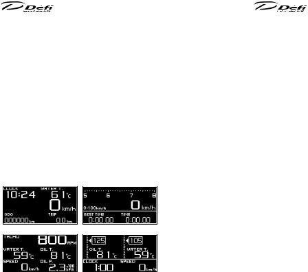
Display pattern can be selected from 4 display modes. (Maximum 6 items can be displayed all together on one GAUGE display.)
3 ListofProducts / OptionalParts
Product name |
Product No. |
Defi-Link Meter ADVANCE ZD |
DF09701 |
|
|
Product name |
Product No. |
Defi-Link ADVANCE Control Unit |
DF07703 |
Defi-Link ADVANCE Control Unit is necessary to operate ADVANCE ZD.
One ADVANCE Control Unit can control up to 7 gauges and ZDs all-in.
■ Optionalparts AD ForADVANCESystemexclusiveuse
|
Part name |
Part No. |
OP1 |
AD Oil press sensor set |
PDF08106SS |
OP2 |
AD Fuel press sensor set |
PDF08205SS |
OP3 |
AD Oil temp sensor set |
PDF08305SS |
OP4 |
AD Water temp sensor set |
PDF08405SS |
OP5 |
AD Ext. temp sensor set |
PDF08505SS |
STREET display
GAUGE1 display
TIME ATTACK display
GAUGE2 display
The display items and the layout can be changed.
Equipped with sequential indicator with 8 LEDs.
Equipped with clock and alarm functions.
Mounting angles are more flexible than conventional productsEquipped with odometer and trip meter
Oil, water, and exhaust temperatures can be displayed from 0 (32°F).Graphic animation plays during idling (Special mode).
59 |
60 |

4 Specification
Powersupplyvoltage |
10V 16V DC(For 12V vehicle |
|
|
||
ADVANCE Control |
+Bline |
2A IGN ON |
|
|
|
unit Current con- |
|
5mA IGN OFF |
|
|
|
sumption |
ILMline |
800mA |
|
|
|
(Maximum value obtained when connecting 7 gauges and ZDs) |
|||||
Operation tem- |
-20 +60 , -4 +140°F Under 80 relative humidity |
||||
perature range |
|||||
|
|
|
|
||
Storage tempera- |
-30 +80 , -22 +176°F Under 80 relative humidity |
||||
ture range |
|
|
|
|
|
Display range |
|
Speed |
0 |
400km/h(0 240MPH) |
|
|
|
Tachometer |
0 |
11,000rpm |
|
|
OP1 |
Oil Pressure |
0 |
1,000kPa(0 145PSI) |
|
|
OP2 |
Fuel Pressure |
0 |
600kPa(0 87PSI) |
|
|
OP3 |
Oil Temperature |
0 |
150 (32 302°F) |
|
|
OP4 |
Water Temperature |
0 |
150 (32 302°F) |
|
|
OP5 |
Exhaust temperature |
0 |
1,100 (32 2,010°F) |
|
|
|
Volt |
10 16V |
||
|
|
Clock |
12 hours display |
||
Applicable speed |
2 4 8 16pulse(mainly for Japanese vehicles) |
||||
pulse |
Pulse free setting: 1,274 16,562pulse/km, |
||||
|
2,051 26,665pulse/mile corresponds to 2 26pulse) |
||||
Applicable number |
1 2 3 4 5 6 8 4cycle |
|
|
||
of cylinders |
|
|
|
|
|
Dimensions |
Refer to part names and dimensions section. |
||||
Weight |
400g, 0.9lb (including box, mounting parts, wires, and accessories |
||||
To display OP1 through OP5 in Display range, the sensor sets OP1 through OP5 need to be purchased separately. (Ex. To display Oil pressure, AD Oil pressure sensor set OP1 needs to be purchased separately.) However, ADVANCE gauges are already installed, the sensor set is not necessary to be purchased separately.
ADVANCE ZD cannot display turbo or intake manifold pressure.
5 Partslist
Blue 4pins
|
|
(2lines) |
|
|
|
|
ZD |
|
Speed & tachometer |
|
Meter wire 0.5m |
|
|
1pc |
signal wire 2m (6 3/5ft) 1pc |
|
(1 3/5ft) 1pc |
|
||
|
|
Components of Brace set |
|
|||
Brace set |
|
|
|
|
|
Hexagon |
|
Knob |
Brace |
Bolt holder |
head bolt |
||
1pc |
|
Components are set in brace. |
|
|||
|
|
|
||||
Accessories |
|
|
|
|
|
|
Double sided tape |
M4 bolt, nut, |
|
|
Mounting |
Soderless |
|
1pc |
|
washer 1pc |
|
bracket 1pc |
connector 2pcs |
|
|
|
Clip |
|
|
Tie wrap |
|
|
|
2pcs |
|
|
2pcs |
|
Operation manual (this booklet), and warranty card are included with the parts listed above.
61 |
62 |

6 Partnames/Dimensionsinmm(inches)
Front |
Side |
Sequential Indicator(8 LEDs)
96.4(3.8)
|
|
51.8(2) |
|
61.5(2.4) |
26.7(1) |
)range |
73(2.9) |
86(3.4)(ZDmovable |
|||
|
|
OLED Display |
|
42(1.7) |
27.8(1.1) |
17.3(0.7) |
DIM Sensor SELECT button SET button Mounting bracket Brace Knob
Backside |
88.2(3.5) |
|
|
45.(1.8) |
|
Connectors |
Connector for |
|
ADVANCE indicator |
||
for meter wires |
||
(Sold separately) |
||
|
Connector for external switch(unused)External switch is not on sale yet.
■ Buttons
In this manual, the SELECT button and the SET button are illustrated as follows:
L SELECT SET R
■ Installationdiagram
Switch unit 


Sensor Wires→Sensors→Connect to vehicle
Power source wire →Connect to vehicle
Meter wire
Meter wire
ADVANCE
Control Unit CR BF
ZD
CR BF CR
ZD
The meter wire can be connected to both two connectors of METER OUTPUT. Up to 7 gauges and displays in all can be connected to one control unit. (Ex. If 7 gauges are connected to one line, none can be connected to the other line. If three gauges are connected to one line, up to 4 gauges can be connected to the other line.)
Do not connect more than one gauge of the same variety. (Ex. You can NOT connect 2 turbo gauges together.) However, several ZDs can be connected.
63 |
64 |

7Installation
7-1.Confirmationofcontents.
Confirm the contents. Refer to 5 Parts list.
7 -2.InstallationofADVANCEControlunitandsensors
InstallADVANCEControlunit,sensors,andsensorwiresbyreferringtothemanuals.Refer to manuals of ADVANCE Control unit, gauges, and sensor sets
7 -3.Wiringofspeedandtachometersignalwire
1.Disconnect the negative(-) battery terminal.
2.Connect the green wire(SP) to SP signal of ECU.
3.Connect the blue wire(TA) to TA signal of ECU. If the tachometer signal wire of ADVANCE series is already wired, connect only the green wire. (Do not use the speed and tachometer signal wire included in this product.)
Refer to how to solder and how to use the solderless connectors.
4.Connect the speed and tachometer signal wire to ADVANCE Control unit. (In case the wire is already connected, skip this step.)
5.Connect the negative(-) battery terminal.
6.Set the speed pulse, number of cylinders, and tachometer response after all the installation and wiring are done by referring operation section.
■ Cautionforwiringofspeedandtachometersignalwires  Caution
  If there is an unconnected wire, be sure to insulate it.
7 -4.InstallationofZDandwiringofmeterwire |
||
1. The bolt holder and the hexagon head bolt |
|
|
are inserted into the slit of brace. And the |
|
|
knob is temporarily fastened. |
|
|
2. Insert convex part of the mounting bracket |
|
|
over the legs of the brace. And Attach the |
|
|
mounting bracket to the brace with the |
Fig.1 Fix brace on bracket |
|
bolt, nut and washer included in the kit as |
||
30 |
||
shown in the figure 1. |
||
17 |
||
3. Cut the buffer into 30x85mm (2 pieces) and |
||
|
||
attach them to the backside of ZD (2 places) |
|
|
as shown in figure 2. |
|
|
4.Connect the meter wire to the connector on the backside of ZD.
5.Insert the bolt holder of brace into the
groove of ZD and then fasten the knob as shown in figure 3. If it is too tight-fitting to insert, unfasten the knob once.
6.Adjust the angle and location to attach. The mounting bracket is bendable to fit on
|
the place to attach. |
|
7. |
Attach double sided tape on backside of |
|
|
the mounting bracket (4 places) as shown |
Fig.3 Insert brace to ZD |
|
in figure 4. Fix ZD on the place where you |
|
|
intend to attach it. |
|
8. |
Confirm the knob and bolts are fastened |
|
|
firmly and ZD is fixed firmly. |
|
9. |
Carry out the final confirmation according |
Screw holes(Φ4.4mm) |
|
to the manual of ADVANCE Control unit. |
Fig.4 Attach tape on bracket |
Refer to manual of ADVANCE Control unit. |
|
|
65 |
66 |
Confirmation
 Use appropriate dashboard cleaning liquids (commercially available) to clean the area where the double sided tape will be attached.
 If the adherence of double sided tape is not enough, use commercial tapping screws(4mm).
7 -5.Settingandcheckingofoperations
Both the switch unit of ADVANCE Control Unit and the buttons on ZD are used to set up and operate. In this manual, each operation is indicated as:
ADVANCE Control unit operation → CUOPR ZD operation → ZDOPR
1. Turn the ignition ON. Confirm DC SOURCE LED of ADVANCE Control unit
lights up.
Refer to manual of ADVANCE Control unit.
2. Confirm the opening mode is performed (and then STREET display mode is
displayed).
Refer to 8 -5. Opening mode, 8 -6-2. Real mode
3.Confirm short-circuit (SHORT) or disconnected (OPEN) errors are not displayed.
Refer to 8 -8. Error display
 If an error is displayed
→Turn the ignition off immediately, and then confirm the wiring of the sensor and the sensor wire.
4.Set up the speed pulse, number of cylinders, and tachometer response in the system setup mode.
Refer to 8 -2. System setup mode
5. Set up the items displayed and warning values.
Refer to 8 -3. Display setup mode, 8 -7. Warning setup mode
6. Confirm ZD functions properly.
 Warning
 Set up while the vehicle is stopped.
8 Operation |
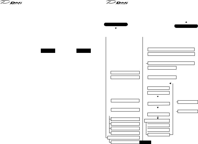
8 -1.Statetransitiondiagram |
|
|
|
|
|
|
|
|
|||||||||||||||||||||||
|
|
|
Defi-Link ADVANCE System is composed as following diagram: |
|||||||||||||||||||||||||||||
|
|
|
|
|
|
|
|
|
|
|
|
|
|
|
|
|
|
|
|
|
||||||||||||
|
Opening mode |
|
|
|
|
|
|
|
|
|
|
|
|
|
|
Ending mode |
||||||||||||||||
|
|
|
|
|
IGN |
ON |
|
|
|
|
|
|
|
|
|
|
|
|
|
|
|
|
IGN |
OFF |
||||||||
|
|
|
|
|
|
|
|
|
|
|
|
|
|
|
|
|
|
|
|
|
|
|
|
|
|
|
|
|||||
|
|
|
|
|
|
|
|
|
|
|
|
|
|
|
|
|
|
|
|
|
|
|
|
|
|
|
|
|
|
|||
|
Real mode( STREET / GAIGE1 / GAIGE2 / TIME ATTACK ) |
|
|
|
|
|
|
|
|
|||||||||||||||||||||||
|
|
|
|
|
|
|
|
|
|
|
|
|
|
|
|
|
|
|
|
|
|
|
|
|||||||||
|
CU OPR |
|
|
|
|
ZD OPR |
|
|
|
|
|
|
|
|
|
|
|
|||||||||||||||
|
|
|
|
|
|
|
|
|
|
|
|
|
|
|
|
|
|
|
|
|||||||||||||
|
|
|
System setup mode(S1) |
|
|
|
Display setup mode(S2) |
|
|
|
|
|
|
|
|
|||||||||||||||||
|
|
|
|
|
|
|
|
|
|
|
|
|
|
|
|
|
|
|||||||||||||||
|
|
|
|
|
Units setting |
|
|
|
|
|
|
REV BAR scale range setting |
|
|
|
|||||||||||||||||
|
|
|
|
|
|
|
|
|
|
|
|
|
|
|
|
|
|
|
|
REV BAR maximum scale value setting |
|
|||||||||||
|
|
|
|
|
Speed pulses setting |
|
|
|
|
|
|
|
|
|||||||||||||||||||
|
|
|
|
|
|
|
|
|
|
|
|
|
||||||||||||||||||||
|
|
|
|
|
|
|
|
|
|
|
|
|
Sequential indicator lighting pattern setting |
|
||||||||||||||||||
|
|
|
|
|
Number of cylinders setting |
|
|
|
|
|
|
|
|
|||||||||||||||||||
|
|
|
|
|
|
|
|
|
|
|
|
|
||||||||||||||||||||
|
|
|
|
|
|
|
|
|
|
|
|
|
|
|
|
|
|
|
|
|
|
|
|
|||||||||
|
|
|
|
|
Tachometer response setting |
|
|
|
|
|
Sequential indicator lighting step setting |
|
|
|||||||||||||||||||
|
|
|
|
|
|
|
|
|
|
|
|
|
|
|
|
|
|
Oil pressure warning limit setting |
|
|||||||||||||
|
|
|
|
|
Dimmer setting |
|
|
|
|
|
|
|||||||||||||||||||||
|
|
|
|
|
|
|
|
|
|
|
||||||||||||||||||||||
|
|
|
|
|
|
|
|
|
|
|
|
|
Warning buzzer setting |
|
||||||||||||||||||
|
|
|
|
|
Special display setting |
|
|
|
|
|
|
|
|
|||||||||||||||||||
|
|
|
|
|
|
|
|
|
|
|
|
|
||||||||||||||||||||
|
|
|
|
|
|
Warm-up setting |
|
|
|
|
|
|
|
|
|
|
|
|
|
|
|
|
||||||||||
|
|
|
|
|
|
|
|
|
|
|
Alarm setting |
|
|
|
|
|
|
|
|
|||||||||||||
|
|
|
|
|
|
|
|
|
|
|
|
|
|
|
|
|
|
|
||||||||||||||
|
|
|
|
|
|
Clock setting |
|
|
|
|
|
|
|
|
Display number setting |
|
||||||||||||||||
|
|
|
|
|
|
|
|
|
|
|
|
|
|
|
||||||||||||||||||
|
|
|
|
|
|
|
|
|
|
|
|
|
|
|
|
|
|
|
|
|
|
|
|
|
||||||||
|
|
|
Display item change |
|
|
|
|
|
|
|
|
|
|
|
|
|
|
|
|
|
|
|
|
|||||||||
|
|
|
|
|
|
|
|
|
|
|
|
|
|
|
|
STREET |
|
|
Display function, etc. |
|||||||||||||
|
|
|
|
|
|
|
|
|
|
|
|
|
|
|
|
|
|
|||||||||||||||
|
|
|
|
|
Display zone size change |
|
|
|
|
|
|
|
Trip reset |
|
|
Warning display |
||||||||||||||||
|
|
|
|
|
|
|
|
|
|
|
|
|
|
|
|
|
|
|
|
|
|
|||||||||||
|
|
|
Brightness adjustment |
|
|
|
|
|
|
Display mode change |
|
|
Diff. press. display |
|||||||||||||||||||
|
|
|
|
|
|
|
|
|
|
|
|
|
|
|
|
|
|
|
|
|
||||||||||||
|
|
|
Real peak mode |
|
|
|
|
|
|
|
|
|
|
|
|
|
|
|
|
|
|
|
|
|
||||||||
|
|
|
|
|
|
|
Realpeak resetmode |
|
|
|
GAUGE1 |
|
|
|
|
Warm-up display |
||||||||||||||||
|
|
|
|
|
|
|
|
|
|
|
|
|
|
Special display |
||||||||||||||||||
|
|
|
|
|
|
|
|
|
|
|
|
|
|
|
|
|
|
|
Display mode change |
|
|
|||||||||||
|
|
|
Record mode |
|
|
|
|
|
|
|
|
|
|
|
|
|
|
|
Error display |
|||||||||||||
|
|
|
|
|
|
|
|
Rec peakmode |
|
|
|
|
|
|
|
|
|
|
|
|
|
|
||||||||||
|
|
|
|
|
|
|
|
|
GAUGE2 |
|
|
|
|
|
|
Alarm |
||||||||||||||||
|
|
|
|
|
|
|
|
|
|
|
|
|
|
|
|
|
|
|
Display mode change |
|
|
|||||||||||
|
|
|
Playback mode |
|
|
|
|
|
|
|
|
|
|
|
|
|
|
|
||||||||||||||
TIME ATTACK
 Time attack measuring
 Best score clearing
Display mode change
ZD OPR
67 |
68 |
 Loading...