

Page 1

Defi-LinkDisplayVSDCONCEPT
OperationManual
NipponSeikiCo.,Ltd.
Page 2
Before Installation(for installation personnel)
W
g
/
m
y
n
n
)
g
.
g
.
ehicles.
(
g
.
).
.
-
).
.
n
prop
g
g.
y.
g
.
y
.
.
g
p
.
y
.
g
absorbe
cause
es.
ys.
s
g.
g
p
.
y.
y.
y
.
p
.
g.
arnin
Carefully consider the installation location and driver's operation of the product before installation. Be
sure not to install the unit where it could fall. Im
to fall and dama
o not disassemble or modify this product. Such actions can not only damage or destroy the product
ut will also void the warrant
Ensure that the vehicle will remain stationary and turn off the engine before installing this product.
Failure to do so could result in a fire, and could make the vehicle move durin
o not perform installation of this product immediately after the engine has been switched off. The engine and
exhaust s
Remove the key from the ignition and disconnect the negative (-) battery terminal prior to installation of this product.
Failure to do so could result in a fire caused by an electrical short circuit
Take care not to install this product in a way that interferes with safety equipment such as seat belts and air ba
systems or vehicle operation equipment such as engine controls, steering wheel or brake systems. Interference with
normal o
Ensure that the wiring of this product does not have an adverse impact on the other wiring of the vehicle. An
controlling devices or other electronic components of the vehicle could be damaged
Use a solderless connector or similar device for wiring connections and make sure connections are insulated. In
areas where there could be tension or sudden impacts on the wirin
ther shock
Please keep children and infants away from the installation area. Children may swallow small parts or be injured in
other wa
eration of the vehicle can result in an accident or fire
e the vehicle or cause serious danger by impeding drivin
stem are extremely hot at this time and can cause burns if touched
nt material. Accidental shorts can
er installation or operation could cause the product
disassemble
odif
installation
, safeguard the wiring with corrugated tubing or
fir
autio
This product is designed for use on 12V vehicles. Do not install this product on vehicles with 24V system
ear gloves to avoid burns when soldering and cuts when working with wirin
hen the negative (-) battery terminal is disconnected, equipment such as clocks and audio
components havin
com
onent to reset data after installation of this product
internal memory may lose their memory data. Follow the operation manual of each
onfirmatio
After installation is complete, return this operation manual to the customer along with the warrant
About Installation and Operation(for customer and installation personnel
arnin
Please have this product installed by the retail store or dealer where it was purchased. Installation by the customer
will void the warrant
In order to ensure safe driving, check the information on this display only for short periods of time. Looking at the
displa
from the unit. If such a condition occurs, contact the sales outlet or installation
the indication of vehicle's ori
v
connector of Defi-Link Control Unit II
Misconnection could dama
Link Control Unit
for long periods of time could distract adequate attention from the road and result in an accident
iscontinue use of this product if nothing is displayed, water gets into the unit, or smoke or a strange odor comes
ersonnel as soon as possible.
ontinued use while the condition exists could result in an accident or fire
o not operate during drivin
autio
Information other than speed and engine speed is not displayed if this product is not connected to Defi-Link System
The speedometer and tachometer display of this product are for reference purposes only. Please drive according to
inally equipped instruments
This product can be used only on 3, 4, 5, 6, and 8 cylinder vehicles with 4 cycle engine. It cannot be used on diesel
hen this product is linked to Defi-Link System, connect the LINK connector of D.C.Unit and the METER OUTPUT1
or the METER connector of Defi-Link Control Unit) with the meter wire.
e the product
hen this product is linked to Defi-Link system, the tachometer signal must be input to Defi-Link Control Unit II(or
efi-Link Control Unit). Set the number of cylinders of Defi-Link Control Unit II(or Defi-Link Control Unit
ata on boost and intake manifold pressure cannot be displayed
hen this product is linked to Defi-Link System, be sure to follow the instructions for Defi-Link Control Unit II(or Defi
o not pull the wires out of connectors by forcefully. The connectors may be broken and the wires may be cut.
hen pulling out the wires, press the lock firmly and unclip the locks of connectors
Page 3
n
e
e
y
g
.
Installation (for installation personnel)
P
g
g
).
n
When the Defi-Link Display VSD CONCEPT is used WITHOUT a connection to the Defi-Link System
arnin
Carefully read the "Before Installation" and "About Installation and Operation" sections of the manual concerning installation
and operation. Then install the product properl
result in the product fallin
from its position or damage to the vehicle
hen installing the display, be sure to follow the instructions for Defi-Link Control Unit II(or Defi-Link Control Unit
and safely. Installation in an unsuitable location or improper installation can
autio
TE
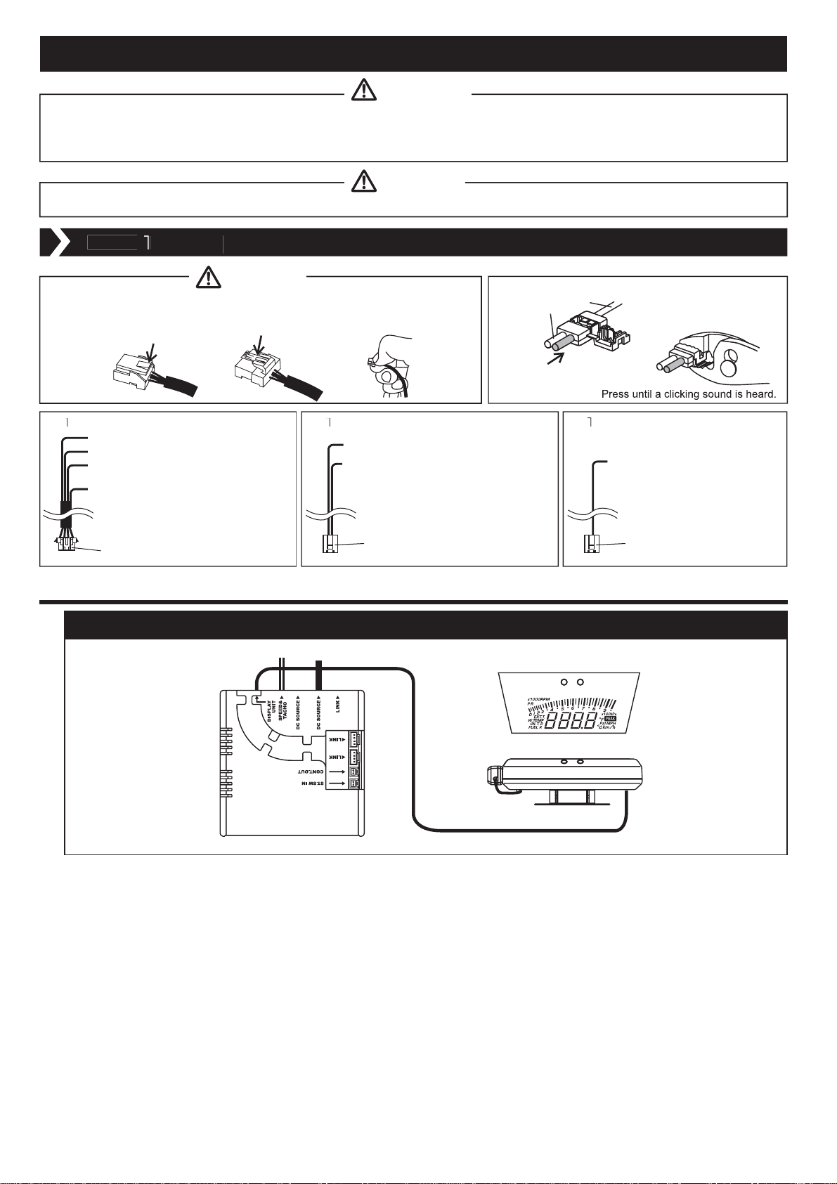
●Do not pull the wires out of connectors forcefully. The connectors and the
wires may be broken. When pulling out the wires, press the lock firmly and
unclip the locks of connectors.
Power supply wire(2 1/2ft, 75cm)
Red:Battery(To 12V battery wire)
Orange:IGN(To 12V wire when ignition on)
Black:GND(To ground, negative
battery terminal)
White:+I LM(To 12V wire when small light on)
※When this product is used without a
connection to the Defi-Link System,
the white wire is not necessary to
be connected. Insulate it.
5Pins(1pin is vacant.)
■When the Defi-Link Display VSD CONCEPT is used WITHOUT a connection to the Defi-Link System
Wirin
Caution
How to branch signal wire using solderless connector
wire from vehicle
Insert wire of attached parts.
Speed & tacho signal wir
ree
:Speed signal
Blue:Tacho signal
Engine computer unit(ECU)
or ignition primary coil
※When connected to Defi-Link System,
do not connect the blue wire but
insulate it.
2Pins
(6 3/5ft, 2m)
Tachometer signal wir
Blue:Tacho signal
Engine computer unit(ECU)
or ignition primary coil
2Pins(1Pin is vacant.)
(4 3/5ft, 2m)
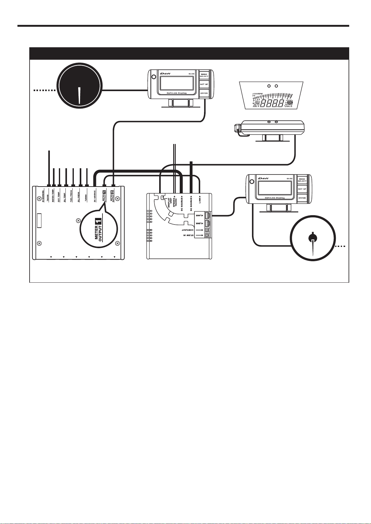
Defi-Link Display VSD CONCEPT Wiring DiagramDefi-Link Display VSD CONCEPT Wiring Diagram
Power supply wireSpeed & tacho signal wire
Display film
DIM sensor
Display unit
D.C.Unit
1:Connect the power supply wire to the wiring of vehicle.(A-1)
2:Connect the other side of the power supply wire to DC SOURCE of D.C.Unit.
※There are two DC SOURCE connectors. Both connectors are usable.
3:Connect the speed & tacho signal wire(green & blue wires) to speed and tacho signal wire of the engine computer
unit(ECU) with solderless connectors.(A-2)
4:Connect the other side of the speed & tacho signal wire to SPEED&TACHO of D.C.Unit.
※In the case where this product is connected to Defi-Link System afterward, connect the white wire of the power
supply wire to the illumination wire(12V wire when small lamp is on) and then connect the tacho signal wire to
Defi-Link Control Unit II(or Defi-Link Control Unit).
Page 4
■When the Defi-Link Display VSD CONCEPT is used WITH a connection to the Defi-Link System
When the Defi-Link Display VSD CONCEPT is used WITH a connection to the Defi-Link System
※These procedures are applicable on condition that Defi-Link Control Unit II(or Defi-Link Control Unit) and the power
supply wire have been installed.
Defi-Link Display VSD CONCEPT and Defi-Link System Wiring Diagram
Display Film
Defi-Link Meter BF
Tachometer signal wire
sensor wires
Defi-Link Control Unit II
(or Defi-Link Control Unit)
METER OUTPUT2
Speed & Tacho signal wire
※Do not connect the blue wire(tacho signal).
Power supply link wire
METER OUTPUT1
Defi-Link Display
Power supply wire
Defi-Link Display
VSD CONCEPT
D.C.Unit
DIM sensor
Defi-Link Display
VSD CONCEPT
Display unit
Display wire
Defi-Link Display
Defi-Link Meter
1:Disconnect the previously connected power supply wire from Defi-Link Control Unit II(or Defi-Link Control Unit).
2:Connect the disconnected power supply wire to DC SOURCE of D.C.Unit.
There are two DC SOURCE connectors. Both connectors are usable.
※
3:Connect DC SOURCEs of Defi-Link Control Unit II(or Defi-Link Control Unit) and D.C.Unit using the attached power
supply link wire.
4:In the case where a meter wire is already connected to METER OUTPUT1 of Defi-Link Control Unit II(or METER of
Defi-Link Control Unit), disconnect the meter wire.(If METER OUTPUT1 of Defi-Link Control Unit II is not in use, skip the
next procedure and go to 6.)
5:Connect the disconnected meter wire to LINK of D.C.Unit.
※There are three LINK connectors. All three connectors are usable.
6:Connect METER OUTPUT 1 of Defi-Link Control Unit II and LINK of D.C.Unit using the attached meter wire.(Connect
METER of Defi-Link Control Unit and LINK of D.C.Unit with the attached meter wire.)
※There are three LINK connectors. All three connectors are usable.
7:Connect the attached tachometer signal wire(blue) to the tacho signal wire of engine computer unit(ECU) using the
attached solderless connector. In the case where a tachometer signal wire(blue) is already connected to D
Control Unit II(or
Defi-Link Control Unit), skip this procedure. Leave the tachometer signal wire(blue) and go to 9.
efi-Link
8:Connect the other side of tachometer signal wire to TACHO of Defi-Link Control Unit II(or Defi-Link Control Unit).
※Be sure to connect the tachometer signal wire(blue) to TACHO of Defi-Link Control Unit II(or Defi-Link Control
Unit). If it is connected to only D.C.Unit, the engine speed will not be displayed.
9:Connect the green wire of speed & tacho signal wire(speed signal) to the speed signal wire of engine computer
unit(ECU) using the attached solderless connector.
※The blue wire of the speed & tacho signal wire is not necessary to be wired. Insulate and bind up the wire so as
not to interfere with driving.(A-2)
10:Connect the other side of the speed & tacho signal wire to SPEED&TACHO of D.C.Unit.
Page 5
y
g
y
g
.
g
.
STEP2 Check Wiring
1:Connect the display wire of Defi-Link Display VSD CONCEPT to DISPLAY UNIT of D.C.Unit.
2:Check that all the wires are properly connected.
3:Turn on the ignition of vehicle and make sure the display is lighted.(The display looks inverted on the display unit.)
4:If the display is lighted, go to the next step. If not, go back to STEP1(WIRING) and rewire.
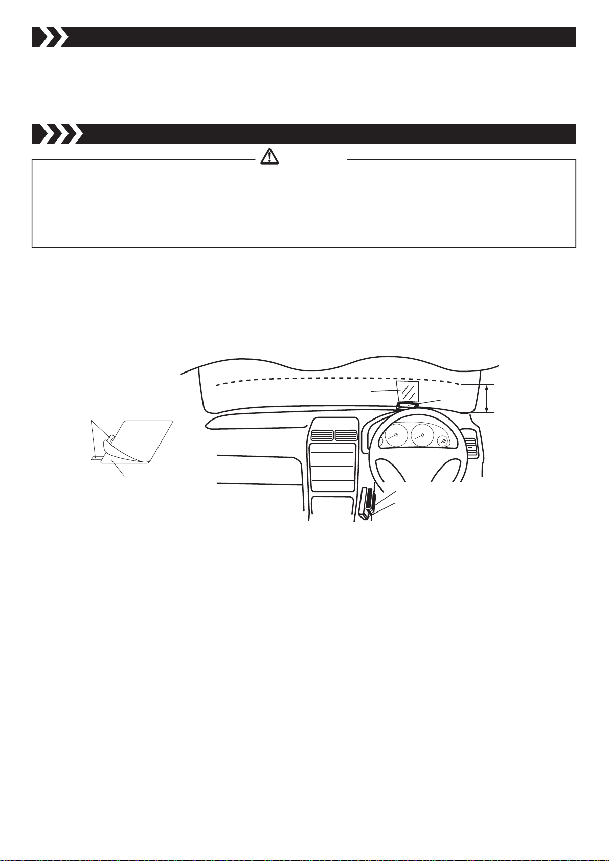
STEP3 Applying the Display Film
arnin
isplay must be projected on the bottom 5in(130mm) of the windshield. Consult with customer about the place of
displa
vehicle safety in your district.
The display is viewable even without the display film. The transmittance of the display film is about 45%. We are
not responsible for an
Please follow the local re
2:Position the display unit and the display film in place. Mark a corner of display film with adhesive tape.
3:Separate the display film from the backing paper using adhesive tape as shown in the following figure.
4:Spray a mixture of water(150ml:5oz) and mild detergent(1 or 2drops) on the windshield and the display film. Attach the
film to the windshield in a longitudinal direction.
5:Gently squeeze out water and air bubbles under the film using a spatula. Wipe extra water with tissue.
projection. Attach the display unit in a location which will not hinder driving. Comply with the law concernin
damage or problems arising from the use of the display film applied on the windshield.
ulations as for attaching the display film
ipe off tarnish and stain on the windshield
※Dismount the display unit for a time to protect it from getting wet. Spread a towel on the instrument panel.
Display film
Adhesive tape
Display film
※Do not expose D.C.Unit and Defi-Link Control Unit II(or Defi-Link Control Unit) to direct sunlight.
Display unit
D.C.Unit
Defi-Link Control UnitⅡ
(or Defi-Link Control Unit)
under 5in
(130mm)
Page 6

ont
STEP4 Installation of Display Unit and DIM Sensor
g.
g.
g
(B-
p
:
.
.
n
arnin
Improper installation could cause the product to fall and damage the vehicle or cause serious danger by impeding drivin
Attach the display unit in a location which will not hinder drivin
Make sure that both the display unit and D.C.Unit are firmly attached.
onfirmatio
hen leaving car under the direct sunlight, cover the display unit with a white cloth. It prevents the unit from deterioration
efore attaching units using double-sided tape, make sure they are clean
Tighten temporarily the bracket A and the display unit using a Phillips screwdriver and adjust the
rotative direction.
racket A can be attached to the display unit in any direction(upside down, front/back). Determine
the location of the display unit where the display is the most clearly projected on the windshield.
2:Tighten temporarily Bracket B and the display unit to adjust the angle using an Allen wrench.(B-2)
3:Identify the location and angle the display unit on the instrument panel. Then fully tighten Bracket A
where the display is clearly projected on the windshield.
4:Connect the DIM sensor to the connector on the backside of display unit.
5:Dismount the display unit from Bracket B. Attach Bracket B on the instrument panel using double-
sided tape. Bend Bracket B fitting to the form of instrument panel. Set Bracket B using sheet-metal
screws(commercialy available).
6:Fit the display unit into Bracket B and fully tighten.
7:Attach the DIM sensor to the side of display unit towards the direction of movement using double-
sided tape.(B-3)
※To perceive the anterior brightness, the sensor must not be interrupted by wipers and things.
Bracket A
Bracket B
Fr
Back
※Use double-sided ta
e as follows
D.C.Unit
Bracket B
DIM sensor
Bracket B
DIM sensor
After the installation is done, the next step is the set-up of functions. Please refer to the backside of this manual.
The quick reference chart for the set-up is printed on the inside of the package.
Page 7

Trouble Shootingfor customer and installation personnel
)
p
.
n
e
n
g
y
.
y.
.
are connected.
or
p
).
y
y.
.
,
.
C
.
g.
g.
y.
.
.
ed.
e manual d
ode is selected
g
.
ode is
y
.
.
y
.
structions
.
y
g.
g
.
.
pped.
y
p
.
g.
.
u
g of
e vehicle
.
g
.
g
.
arnin
If operation of the product seems unusual, inspect the product to confirm that there is no malfunction. If an
o
erational problem has occurred, it could result in an accident
In addition to a general inspection of the product, use the following table to confirm proper operation of the unit. If the
operational problem does not appear in the followin
table, contact the installation personnel
onditio
oes not displa
The engine speed is not
displa
ed correctl
The speed is not displayed
correctl
The auto dimmer m
on, but the display is dark
r thebrightness of the
displa
doesn't change
oes not carry out the
closin
mode
The product is connected to
the Defi-Link S
the s
eed is not recorded
witching of the unit
ill
mination is not
interlocked with switchin
th
stem, but
illumination
Possible Caus
iring of the power supply wire or the
displa
wire is improper
iring of the tachometer signal wire is
wrong.
○Setting of the number of cylinders is
wrong(D.C.Unit/Defi-Link Control Unit
II/Defi-Link Control Unit).
○LINK of D.C.Unit and METER OUTPU
of Defi-Link Control Unit II
○The tachometer signal wire is not
connected to Defi-Link Control Unit II
Defi-Link Control Unit (in the case that
the
roduct is connected to the Defi-Link
stem
iring of the speed signal wire is
wron
etting of the speed pulse is wron
TheIM sensor is not connect
○The front of the DIM sensor is
obstructed.
○Th
the settin
The wiring of the red line of the power
suppl
The REC button is pressed when the
vehicle is sto
The condition is normal
immer m
of the illumination control
wire is wron
in
orrective Actio
Check wiring as per instructions in this manual
Check wiring as per instructions in this manual
Check the number of cylinders as per instructions
in this manual
efi-Link Control Unit manual
2
onnect LINK of D.C.Unit and METER OUTPUT1
of Defi-Link
Connect the tachometer signal wire to Defi-Link
ntrol Unit II(or Defi-Link Control Unit).
Check wiring as per instructions in this manual
Check the speed pulse as per instructions in this
anual
Connect the DIM sensor as per instructions in this
nual
Attach the DIM sensor in a position without an
obstruction which interrupts the front of the sensor
Reset the illumination control setting as per
in
Check wiring as per instructions in this manual
Press the REC button when the vehicle is movin
witching of D.C.Unit illumination is interlocked
with turnin
Defi-Link Control Unit II manual, or
ontrol Unit II using the meter wire
in this manual
on/off the ignition
Page 8

Operation(for customer)
.
.
n
g
emItem
g
g
e
s
p
y
g
s
)/
0
)
0
)/
0
)
a
/h
ual
y
r
g
l
t
1.Set-Up Mode(Screen for setting units and display data parameters)
onfirmatio
e sure to make preparatory settings. The unit will not operate properly without settings being made
et up while the vehicle is stopped
hen changing the factory settings shown below, pressing the SET UP(ENTER) button for more than 2 seconds after the
openin
the SELECT▽ or BAR SELECT▲ buttons are pressed. When adjustment of a particular setting is needed, press the
ENTER button. To quit the set-up mode, press the SET UP(ENTER) button for more than 2 seconds.
mode has completed will bring up the setting mode for units. In set-up mode, the item to be set changes each time
It
nit
eed Puls
Number of Cylinder
arm-U
pecial Displa
achometer Warnin
①Setting of Units
Press ENTER button when the following figure is displayed. Use
units
(kPa、℃、km/h or PSI、°F、MPH), then press ENTER to set the desired units.
Set-up mode Units setting
Factory Settin
P
ater Temp. 40
Oil Temp. 6
m
104F
140F
ar Displa
arning Buzze
Auto Warnin
Illumination Contro
ontrol Ou
SELECT/BAR SELECT button to select
Factory Settin
Man
ater Temp. 8
Oil Temp. 10
176F
212F
②Setting of Speed Pulse
Press ENTER button when the following figure is displayed. Use SELECT/BAR SELECT button to select the
speed pulse number, then press ENTER button to set the selection.
24816 FREE(Free pulse setting)
Speed pulse setting
<
Speed pulse number>
<Free
pulse setting
The speed pulse number differs by model of vehicle. Consult your local car dealer if
you are not certain of the speed pulse number for your vehicle.
>For vehicles having a speed pulse outside 2, 4, 8, 16 pulse, the speed pulse can be set
by switching to the "FREE" screen by pressing and holding the ENTER button for more
than 2 seconds. After the screen changes to pulse set screen(SET.P blinks), press
ENTER button while the vehicle is moving at 60km/h or 40MPH.
※Ask fellow passengers to set up. Do not set up at the wheel.
※It may be unable to be adapted for some models of vehicle.
Page 9

Pulse free setting Hold Speed pulse setting
NOTE: The pulse free setting needs to be done again if units are changed.
NOTE: If the Defi-Link Display VSD CONCEPT is linked with the Defi-Link System, the setting of Defi-
Link Control Unit II(or Defi-Link Control Unit) is prioritized.
NOTE: This function operates when the Defi-Link Display VSD CONCEPT is linked with the Defi-Link
System and the temperature sensor is connected.
Press ENTER button while the vehicle is moving at 60km/h or 40MPH.
NOTE: The pulse free setting needs to be done again if units are changed.
③Setting of Number of Cylinders
Press ENTER button when the following figure is displayed. Use
SELECT/BAR SELECT button to select
the number of cylinders, then press ENTER button to set the selection.
34568
Number of cylinders setting
Set 2 rotary engine at 4 cylinders and 3 rotary engine at 6 cylinders.
NOTE: If the Defi-Link Display VSD CONCEPT is linked with the Defi-Link System, the setting of Defi-
Link Control Unit II(or Defi-Link Control Unit) is prioritized.
④Setting of Warm-Up
Press ENTER button when the following figure is displayed. Use
SELECT/BAR SELECT button to select
water temperature, oil temperature, or OFF. Then press ENTER button to set the selection. Use
SELECT/BAR SELECT button to set the desired temperature. If SELECT/BAR SELECT button is pressed
and held, the number is fast-forwarded.
Range of setting
W.TEMP OIL T. OFF
Water temp: 21℃〜120℃(69°F〜248°F)
Oil temp: 51℃〜150℃(123°F〜302°F)
Warm-Up setting
NOTE: This function operates when the Defi-Link Display VSD CONCEPT is linked with the Defi-Link
System and the temperature sensor is connected.
⑤Setting of Special Display
If ON is selected, the engine speed is displayed in digital when speed is 0km/h or 0MPH for more than 10
seconds. Press ENTER button when the following figure is displayed. Use SELECT/BAR SELECT button
to select ON or OFF.
ON OFF
Special display setting
Page 10

⑥Setting of Tachometer Warning
NOTE: If the Defi-Link Display VSD CONCEPT is linked with the Defi-Link System, the tachometer
warning2 cannot be set. The setting value of the tachometer warning of Defi-Link Control Unit
II(or Defi-Link Control Unit) is applied as a tachometer warning2. Please set up the tachometer
warning of Defi-Link Control Unit II(or Defi-Link Control Unit) higher than the tachometer
warning1 value. If the value is set lower than the warning1, the warning1 will be invalid.
NOTE: If the Defi-Link Display VSD CONCEPT is linked with the Defi-Link System, the warning buzzer
of Defi-Link Control Unit II cannot be absorbed.
Press ENTER button when the following figure is displayed. Green LED is lighted up. Use
SELECT button to
up. Use
SELECT/BAR SELECT button to
set the desired warning1 value. Press ENTER again. Green and red LEDs are lighted
set the desired warning2 value. If SELECT/BAR SELECT button
SELECT/BAR
is pressed and held, the number is fast-forwarded.
Range of setting
Tachometer Warning1:1,000RPM〜9,900RPM
Tachometer Warning2:larger value than warning1〜9,900RPM
Tachometer Warning setting
Tachometer Warning1 setting
(Green LED lights up.)
NOTE: If the Defi-Link Display VSD CONCEPT is linked with the Defi-Link System, the tachometer
warning2 cannot be set. The setting value of the tachometer warning of Defi-Link Control Unit
II(or Defi-Link Control Unit) is applied as a tachometer warning2. Please set up the tachometer
warning of Defi-Link Control Unit II(or Defi-Link Control Unit) higher than the tachometer
warning1 value. If the value is set lower than the warning1, the warning1 will be invalid.
Tachometer Warning2 setting
(Green & red LEDs light up.)
⑦Setting of bar display
Press ENTER button when the following figure is displayed. Use SELECT/BAR SELECT button to select
ON or OFF of the bar display.
Bar Display setting
⑧Setting of Warning Buzzer
Press ENTER button when the following figure is displayed. Use SELECT/BAR SELECT button to select
ON or OFF of the warning buzzer.
Warning Buzzer setting
NOTE: If the Defi-Link Display VSD CONCEPT is linked with the Defi-Link System, the warning buzzer
of Defi-Link Control Unit II cannot be absorbed.
Page 11

⑨Setting of Auto Warning
NOTE: This function operates when the Defi-Link Display VSD CONCEPT is linked with the Defi-Link
System and the temperature sensor is connected.
NOTE: This function operates when the Defi-Link Display VSD CONCEPT is linked with the Defi-Link
System.
When the auto dimmer mode is on, the brightness of the display is adjusted automatically. Press
ENTER to Select one from three stages of brightness in the auto dimmer mode during the real mode or
the peak mode. When the manual dimmer mode is on, the brightness of the display can be set
manually at 5 stages in the real mode or the peak mode.
Press ENTER button when the following figure is displayed. Use SELECT/BAR SELECT button to select
ON or OFF of the auto warning function.
Auto warning setting
NOTE: This function operates when the Defi-Link Display VSD CONCEPT is linked with the Defi-Link
System.
⑩Setting of Illumination Control
Press ENTER button when the following figure is displayed. Use SELECT/BAR SELECT button to select
auto or manual of the dim control mode.
Dim Control setting Auto dimmer modeManual dimmer mode
When the auto dimmer mode is on, the brightness of the display is adjusted automatically. Press
ENTER to Select one from three stages of brightness in the auto dimmer mode during the real mode or
the peak mode. When the manual dimmer mode is on, the brightness of the display can be set
manually at 5 stages in the real mode or the peak mode.
⑪Setting of Control Output
Press ENTER button when the following figure is displayed. Use
water temperature, oil temperature, or OFF. Then press ENTER button to set the selection. Use
SELECT/BAR SELECT button to set the desired temperature. If SELECT/BAR SELECT button is pressed
and held, the number is fast-forwarded.
W.TEMP OIL T. OFF
Control Output setting
SELECT/BAR SELECT button to select
Range of setting
Water temp:21℃〜120℃(69°F〜248°F)
Oil temp:51℃〜150℃(123°F〜302°F)
NOTE: This function operates when the Defi-Link Display VSD CONCEPT is linked with the Defi-Link
System and the temperature sensor is connected.
Page 12

When the Defi-Link Display VSD CONCEPT is used WITHOUT a connection to the Defi-Link System
2. Opening and Ending Mode
Opening and ending modes are performed after the ignition key is turned on and off.
Opening mode
Ending mode
3. Operation Mode
Illumination control
When the auto dimmer mode is selected in the setting of illumination control, the brightness of display is
adjusted automatically depending on the outside light. The brightness can be selected from three stages by
pressing the DIM(ENTER) button. When the manual dimmer mode is selected, the brightness of display is
fixed. The brightness can be selected from five stages by pressing the DIM(ENTER) button.
DARKBRIGHT
Auto dimmer mode
Manual dimmer mode
■When the Defi-Link Display VSD CONCEPT is used WITHOUT a connection to the Defi-Link System
M-5 M-4 M-3 M-2 M-1
A-L3 A-L2 A-L1
①Real Mode
The actual vehicle speed is displayed digitally and the engine speed is displayed in
the bar section. When the engine speed exceeds the warning value set as the
tachometer warning1 in the setting of tachometer warning, the green LED lights up.
When it exceeds the tachometer warning2, the green and red LEDs blink.
②Peak Mode
Pressing the PEAK button during Real Mode will bring up Peak Mode. Recorded
peak values for speed and engine speed will be displayed. Pressing the PEAK button
again during Peak Mode will return to Real Mode.
③Peak Reset Mode
During either Real Mode or Peak Mode, the peak values will be reset by pressing and
holding the PEAK button for more than two seconds.
④Special Display Mode
If Special Display Mode is turned on in the setting of special display and speed is
0km/h or 0MPH for more than 10 seconds in Real Mode, special display will start. In
this mode, the engine speed is displayed digitally. When speed is more than 0km/h or
0MPH or when any button of D.C.Unit is pressed, the display will return to Real Mode.
Page 13

■When the Defi-Link Display VSD CONCEPT is used WITH a connection to the Defi-Link System
When the Defi-Link Display VSD CONCEPT is used WITH a connection to the Defi-Link System
NOTE: If "MPH,
F, PSI" is selected in the
setting of units, data other than
the engine speed is not displayed.
NOTE: If "MPH,
F, PSI" is selected in the
setting of units, data other than
the engine speed is not displayed.
NOTE: When connected to the Defi-Link System, the PEAK button of the D.C.Unit is unavailable.
NOTE: When connected to the Defi-Link System, the PEAK button of the D.C.Unit is unavailable.
※For operations ① through ⑨ shown below, refer to the Operation Manual for Defi-Link Control Unit II(or Defi-
Link Control Unit.
①Real Mode
The actual data on current speed, engine speed, oil pressure, fuel pressure, oil temperature, water temperature, and
exhaust temperature is displayed in this mode. Each time the SELECT/BAR SELECT button is pressed, the displays
of the digital and bar section will change in the following order. Data without sensors connected cannot be selected.
Digital Display
Section
Bar Display
Section
When the engine speed exceeds the warning value set as the tachometer warning1 in the setting of
tachometer warning, the green LED lights up. When it exceeds the tachometer warning2, the green and red
LEDs blink. The tachometer warning2 cannot be set in the setting of tachometer warning.
Speed Oil temp. Oil press. Fuel press.Exhaust temp.
Engine speed Fuel press.Oil press.
Water temp.
NOTE: If "MPH,
setting of units, data other than
the engine speed is not displayed.
°F, PSI" is selected in the
②Peak Mode
By pressing the PEAK button of Defi-Link Control Unit II(or Defi-Link Control Unit) during Real Mode, Peak
values are displayed. Displayed data will be changed by pressing SELECT/BAR SELECT button. Pressing the
PEAK button again during Peak Mode will return to Real Mode.
Digital Display
Section
Bar Display
Section
NOTE: When connected to the Defi-Link System, the PEAK button of the D.C.Unit is unavailable.
Speed Maximum Speed Minimum Engine speed
Note)When displaying the speed minimum value, the unit(km/h or MPH) blinks and the
minimum value recorded in Rec Mode is displayed.
Engine speed Fuel press.Oil press.
NOTE: If "MPH,
setting of units, data other than
the engine speed is not displayed.
Water temp.
Oil temp.Oil press.Fuel press. Exhaust temp.
°F, PSI" is selected in the
③Peak Reset Mode
When the UP button of the Defi-Link Control Unit II is pressed in Peak Mode(or when
the PEAK button of the Defi-Link Control Unit is pressed and held for more than two
seconds in any of Real Mode, Peak Mode or Warning Mode), the peak values will be
reset.
NOTE: When connected to the Defi-Link System, the PEAK button of the D.C.Unit is unavailable.
④Special Display Mode
If Special Display Mode is turned on in the setting of special display and speed is
0km/h or 0MPH for more than 10 seconds in Real Mode, special display will start. In
this mode, the engine speed is displayed digitally. When speed is more than 0km/h or
0MPH or when any button of D.C.Unit is pressed, the display will return to Real Mode.
Page 14

I)If the auto warning mode is turned ON in the setting of auto warning
II)If the auto warning mode is turned OFF in the setting of auto warning
⑤Warning Set Mode
Oil Temp.Engine Speed
Pressing the WARN SET button of Defi-Link Control Unit II(or pressing the SELECT button of Defi-Link Control Unit)
will bring up Warning Set Mode. To set the warning value, please refer to the operations manual of Defi-Link Control
Unit II(or Defi-Link Control Unit).
Boost
※Examples of display
⑥Warning Mode
When current values exceed the values set as warnings by using Defi-Link Control Unit II(or Defi-Link Control
Unit) and when disconnection or short circuit of sensor wires or sensors are detected, the screen indicates the
warning.
※Priority is given to the tachometer warnings over other warnings.
※Warnings on boost and intake manifold pressure are not indicated.
※The warning on oil pressure is not indicated while the vehicle speed is under 10km/h(6MPH).
I)If the auto warning mode is turned ON in the setting of auto warning
When a current value exceeds the set value, the red LED and the name of the data blink. A buzzer sounds
at the same time if warning buzzer is turned on. One minute later, the red LED and the name of the data
stop blinking and start lighting and the current warning value is displayed. When several values exceed the
warning set values, the latest warning is indicated. Pressing the ENTER button will return to the last display
before the indication of warnings. If the value still exceeds the set value, the name of the data will continue
to blink.
II)If the auto warning mode is turned OFF in the setting of auto warning
When a current value exceeds the set value, the red LED and the name of the data blink. A buzzer sounds
at the same time if warning buzzer is turned on. One minute later, the red LED goes out, the buzzer is
stopped, and the name of the data blinks faster. The red LED lights up and a buzzer sounds again if the
warning data is selected to display in the digital display section by using the SELECT button. When several
values exceed the warning set values, the name of data which is being displayed in the digital display
section light up and other names blink.
⑦Self-Diagnosis Function
Disconnection(open)
This display means that a wire disruption, disconnection or improper wiring
connection has occurred at the sensor or in the sensor wire.
Short circuit
This display means that a short circuit has occurred somewhere at the sensor or in
the sensor wire.
Serial error
This display means that communications between Defi-Link Display VSD CONCEPT
and the Defi-Link system have been interrupted.
Setting Error of number of cylinders
"x1000RPM" blinks if the number of cylinders of Defi-Link Control Unit II(or Defi-Link
Control Unit) is not set or if the METER OUTPUT2 connector of Defi-Link Control Unit
II and the LINK connector of D.C.Unit is connected by error.
Page 15

⑧Rec Mode
NOTE: Even if REC button is pressed in vehicle's stopped condition, the vehicle speed data cannot be
recorded and Rec Mode will turn to Play Mode.
.
.
.
y.
NOTE: Once pause, fast-forward or rewind is performed with Defi-Link Control Unit II(or Defi-Link Control Unit), the
recorded speed data cannot be played back. To play back the speed data, Play Mode needs to be started
over again. Operation needs to be performed in vehicle's stopped condition. If the PLAY button is pressed
in vehicle's running condition, speed data will not be played back but Play Mode will turn to Rec Mode.
When the vehicle is moving at the speed of 1km/h(1MPH) or more, connected sensor
data and the speed data are recorded for a maximum of 3 minutes by pressing the
REC button of Defi-Link Control Unit II(or Defi-Link Control Unit). "R" is displayed
during recording. Data displayed in the digital and bar display section can be
changed by pressing SELECT/BAR SELECT button.
NOTE: Even if REC button is pressed in vehicle's stopped condition, the vehicle speed data cannot be
recorded and Rec Mode will turn to Play Mode.
⑨Play Mode
When the vehicle speed is 0km/h(0MPH), recorded data are displayed by pressing the
PLAY button of Defi-Link Control Unit II(or by pressing the PLAY/REC button of DefiLink Control Unit during Peak Mode). "P" is displayed during playing of data. Data
displayed in the digital and bar display section can be changed by pressing
SELECT/BAR SELECT button.
NOTE: Once pause, fast-forward or rewind is performed with Defi-Link Control Unit II(or Defi-Link Control Unit), the
recorded speed data cannot be played back. To play back the speed data, Play Mode needs to be started
over again. Operation needs to be performed in vehicle's stopped condition. If the PLAY button is pressed
in vehicle's running condition, speed data will not be played back but Play Mode will turn to Rec Mode.
⑩Warm-Up Mode
This Warm-Up Mode is available when either a water temperature sensor or an oil temperature sensor is
connected to Defi-Link Control Unit II(or Defi-Link Control Unit) and the setting of Warm-Up is completed. After
Opening Mode, Warm-Up Mode starts if the sensor data is below the set value. During this mode, leftmost
digital segments are lighted in order. If the displayed data is changed by pressing the SELECT button during
this mode, the unit of temperature blinks(℃/°F). When the temperature reaches the set value, Warm-Up Mode
is completed and returns to Real Mode.
⑪Control Output
This Control Output function is available when either a water temperature sensor or an oil temperature sensor
is connected to Defi-Link Control Unit II(or Defi-Link Control Unit) and the setting of Control Output is
completed.
CONT. OUT of D.C.Unit.
When the temperature reaches the set value, the Control Output signal is read out to the terminal of
aution
o not connect anything to the CONT. OUT connector unless this function is used
Load current of the Control Output is less than 300mA
hen the special display is performed, the Control Output signal is not read out
Any damages to other products connected to the CONT. OUT connector is not covered by the warrant
a)Example on direct hookup of a
warning lamp
Connect to 12V wire when ignition
is on.
b)Example of how to connect a motor by using a relay and how to
load a LED indicator
Connect to 12V wire when ignition is on.
Diode
Lamp
CONT. OUT
connector(red)
Relay
Motor
Resistor
LED
Indicator
CONT. OUT
connector(red)
Page 16

Simplified Set-up Chart
SET: Setting of units "kPa, ℃, km/h" or "PSI, °F, MPH"
SPEED SET: Setting of speed pulse
PULSE-4: Select the proper speed pulse from 2, 4, 8, and 16.
FREE: Set speed pulse other than 2, 4, 8, or 16.
TACHO-SET: Setting of number of cylinders
ENGINE-4: Select the proper number of cylinders from 3, 4, 5, 6, and 8.
WARM-UP: Setting of warm-up function
SPECIAL: Choose ON or OFF of special display.
TACHO-REV: Setting of warning value for engine speed
TACHO-BAR: Choose ON or OFF of bar display.
WARNING-BUZZER: Choose ON or OFF of buzzer sound.
AUTO-WARNING: Choose ON or OFF of auto warning display.
DIMMER: Choose AUTO or MANUAL of illumination control.
AUTO-DIMMER: Auto dimmer control
MANUAL-DIMMER: Manual dimmer control
AUTO-LEVEL3: Select one from three levels of brightness in auto dimmer mode.
MANUAL-3: Select one from five levels of brightness in manual dimmer mode.
CONTROL-OUT: Setting of control output function
OPEN: Disconnection of wire and/or sensor is detected.
SHORT: Short circuit of wire and/or sensor is detected.
ERROR: Serial error is detected.
Refer to the operation manual for the details.
 Loading...