

Page 1

INSTALLATION INSTRUCTIONS
BENT END SIDEBARS
09-12 FORD F-150 SUPER CREW CAB
PART # DZ 372691/DZ 372692/DZ372693
Page 2
BENT END SIDEBARS
09-11 FORD F-150 SUPER CREW CAB
Page 1 of 4 10/26/11 Rev1(DP)
PARTS LIST:
1
Driver/Left Sidebar
4
1/2” Lock Washers
1
Passenger/Right Sidebar
4
12mm x 32mm OD x 3mm Flat Washers
1
Driver/Left Front Mounting Bracket
4
12mm Lock Washers
1
Passenger/Right Front Mounting Bracket
4
12mm Hex Nuts
2
Support Brackets
4
10-1.50mm x 30mm Hex Bolts
1
Driver/Left Top Mounting Bracket
4
10-1.50mm x 35mm Hex Bolts
1
Passenger/Right Top Mounting Bracket
6
10mm x 30mm OD x 2.5mm Flat Washers
1
Driver/Left Rear Mounting Bracket
8
10mm x 20mm OD x 2mm Flat Washers
1
Passenger/Right Rear Mounting Bracket
8
10mm Lock Washers
2
12mm x 40mm x 10mm Nut and Bolt Plate
6
10mm Hex Nuts
2
12mm x 40mm Bolt Plates
4
8-1.25mm x 30mm Hex Bolts
4
12mm Plastic Retainers
4
8mm x 24mm OD x 2mm Flat Washers (Outer)
2
10mm Plastic Retainers
4
8mm x 16mm OD x 1.6mm Flat Washers (Inner)
4
1/2" x 2” Hex Bolts
4
8mm Lock Washers
4
1/2” x 1-1/4” OD x 3/32” Flat Washers
4
8mm Hex Nuts
PROCEDURE:
1. REMOVE CONTENTS FROM BOX. VERIFY ALL PARTS ARE PRESENT. READ
INSTRUCTIONS CAREFULLY BEFORE STARTING INSTALLATION. DRILLING M AY BE
REQUIRED. ASSISTANCE RECOMMENDED.
2. Starting at the front of the driver side of the vehicle, remove the two small hex bolts and the
metal clips holding the bottom of the fender to the body, (Figure 1A). NOTE: Use a small flat
screwdriver to spread the clip apart for easy removal. Due to body panel misalignment from
the factory, it may be necessary to open these holes slightly with a 3/8" drill bit, (Figure 1B).
3. Select the driver side front Mounting Bracket. Line up the (2) holes in the pinch weld with the
holes in the front Mounting Bracket. Insert (2) 8mm x 30mm Hex Bolts with (2) 8mm x 24mm
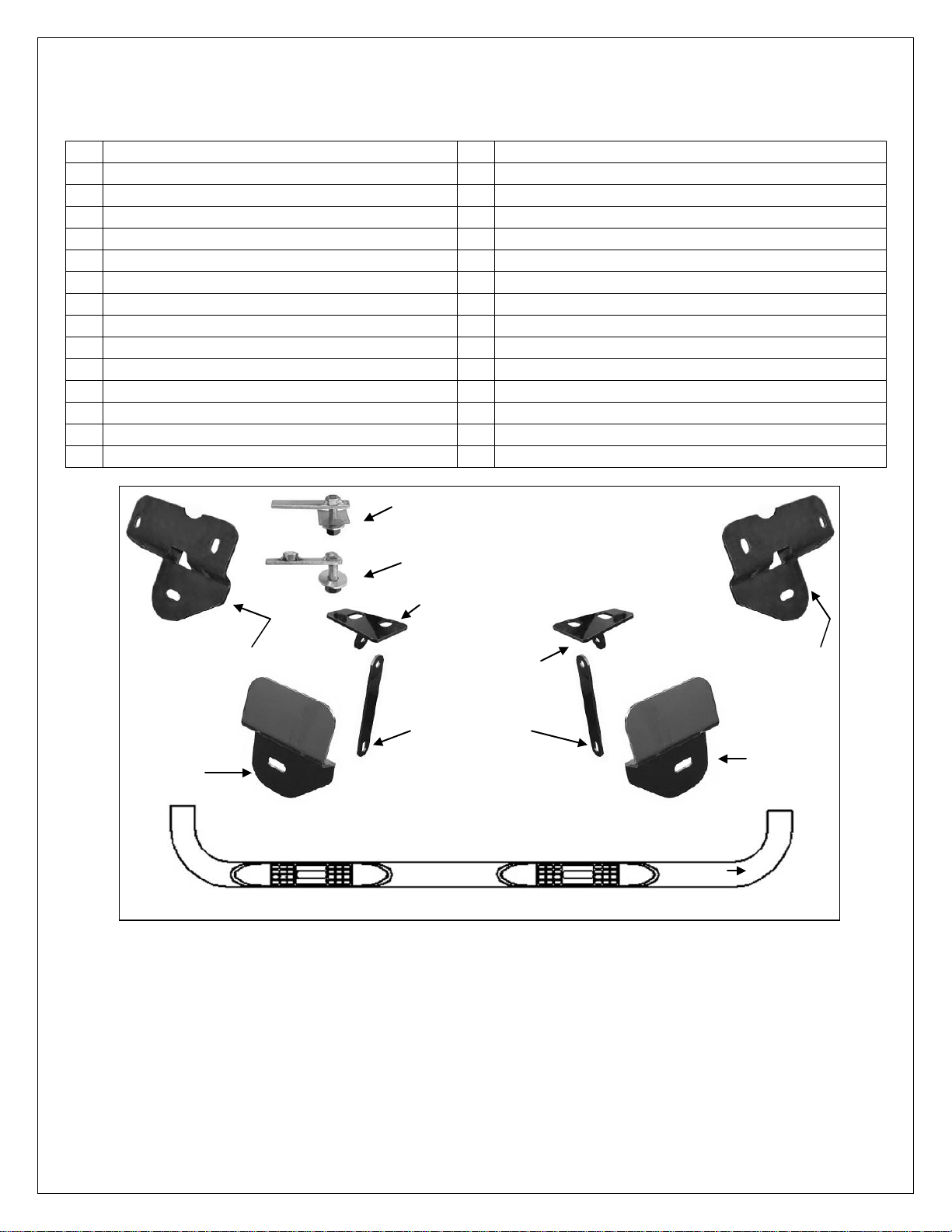
Passenger/Right
Front Mounting
Bracket
Passenger/Right
Rear Mounting
Bracket
12mm x 40mm x 10mm
Nut and Bolt Plate
12mm x 40mm Bolt Plate
Passenger/Right
Top Bracket
Drive/Left
Top Bracket
(2) Front Support
Straps
Driver/Left Rear
Mounting Bracket
Driver/Left
Front
Mounting
Bracket
Passenger Sidebar illustrated
Front
Page 3

BENT END SIDEBARS
09-11 FORD F-150 SUPER CREW CAB
Page 2 of 4 10/26/11 Rev1(DP)
OD x 2mm Large Flat Washers up from below and secure with (2) 8mm x 16mm OD x 1.6mm
Small Flat Washers, (to clear the bracket), (2) 8mm Lock Washers and (2) 8mm Hex Nuts,
(Figure 2). Do not tighten hardware at this time.
4. Next, locate the round and square holes in the floor panel next to the body mount. Select (1)
12mm x 40mm x 10mm Nut and Bolt Plate and thread (1) 12mm Plastic Retainer part way onto
it, (Figure 3A). Insert the Nut and Bolt Plate into the square hole in the floor, (Figure 3B). Line
up the nut on the Nut and Bolt Plate with the round hole. IMPORTANT: The Plastic Retainer is
designed to prevent the Bolt Plate from falling into the body cavity and to aid in mounting the
Bracket. After inserting, thread the Plastic Retainer down flush against the body panel. NOTE:
For passenger side installation, temporarily remove the ground strap if interfering with install.
5. Select the driver side Top Bracket. Hold the Top Bracket in place over the Nut and Bolt Plate.
Secure the Bracket to the Nut and Bolt Plate with (1) 12mm Flat Washer, (1) 12mm Lock
Washer and (1) 12mm Hex Nut, (Figure 4). Rotate the Nut and Bolt Plate to line up the Nut
with the remaining hole and thread (1) 10mm x 35mm Hex Bolt, (1) 10mm x 30mm OD Large
Flat Washer and (1) 10mm Lock Washer into the Nut, (Figure 5). Do not tighten hardware.
6. Select (1) Support Strap. Bolt the round hole on the Support Strap to the backside of the tab
on the Top Bracket with (1) 10mm x 30mm Hex Bolt, (2) 10mm x 20mm x 2mm Small Flat
Washers, (1) 10mm Lock Washer and (1) 10mm Hex Nut, (Figure 6). Line up the slotted end
of the Support Bracket with the tab on the back of the Mounting Bracket with the Support Strap
on the forward facing side of the tab. Bolt the Strap to the tab with (1) 10mm x 30mm Hex Bolt,
(2) 10mm x 20mm x 2mm Small Flat Washers, (1) 10mm Lock Washer and (1) 10mm Hex Nut,
(Figure 6). Do not tighten hardware at this time.
7. Move toward the rear of the vehicle and remove the tape covering the holes on the inner body
panel. Select (1) 12mm Bolt Plate and thread (1) 12mm Plastic Retainer part way onto it,
(Figure 7A). Insert the Bolt Plate and Retainer into the rear mounting hole, (Figure 7B), as
described in Step 4.
8. Hang the driver side Rear Mounting Bracket from the Bolt Plate and secure it with the included
(1) 12mm Lock Washer, (1) 12mm Flat Washer, and (1) 12mm Hex Nut, (Figure 7B). Insert (1)
10mm x 35mm Hex Bolt, (1) 10mm x 30mm OD Large Flat Washer with (1) 10mm Plastic
Retainer into the hole at the rear of the Mounting Bracket from the outside-in, (Figures 8A &
8B). NOTE: The Plastic Retainer is intended to protect the outer painted surface of the body.
Thread the Plastic Retainer onto the Hex Bolt so that it is between the 10mm Large Flat
Washer and the body. Secure the Bracket with (1) 10mm Lock Washer, (1) 10mm x 30mm
Large Flat Washer and (1) 10mm Hex Nut. Do not tighten hardware at this time.
9. Attach the Sidebar to the Mounting Brackets using the included (2) 1/2” x 2” Hex Bolts, (2) 1/2”
Flat Washers, and (2) 1/2” Lock Washers, (Figure 9). Do not tighten hardware at this time.
10. Align the Sidebar and adjust as required. Once properly aligned, tighten all hardware.
11. Repeat Steps 2 - 10 for passenger Sidebar installation. NOTE: Once passenger side
installation is completed, reinstall the ground strap next to the mounting holes for the front
Mounting Bracket as removed in Step 4.
12. Do periodic inspections to the installation to make sure that all hardware is secure and tight.
To protect your investment, wax this product after installing. Regular waxing is recommended to add a
protective layer over the finish. Do not use any type of polish or wax that may contain abrasives that could
damage the finish.
For stainless steel: Aluminum polish may be used to polish small scratches and scuffs on the finish. Mild
soap may be used also to clean the Sidebar.
For gloss black finishes: Mild soap may be used to clean the Sidebar.
Page 4

BENT END SIDEBARS
09-11 FORD F-150 SUPER CREW CAB
Page 3 of 4 10/26/11 Rev1(DP)
Driver Side Installation Pictured
(2) 8mm x 30mm Hex Bolts
(2) 8mm Lock Washers
(2) 8mm x 24mm Large Flat Washers (outer)
(2) 8mm x 16mm Small Flat Washers (inner
against Bracket)
(2) 8mm Hex Nuts
Remove these two hex bolts and metal clip
nuts. Drill a 3/8" hole through the pinch
weld to clearance holes ONLY if necessary
(Fig 2) Driver side front Mounting Bracket pictured
Fig 1A
(1) 10mm x 35mm Hex Bolt
(1) 10mm Large Flat Washer
(1) 10mm Lock Washer
(1) 12mm Flat Washer
(1) 12mm Lock Washer
(1) 12mm Hex Nut
Front
Front
Front
Insert the Nut and
Bolt Plate into
square hole and
line up the nut with
the round hole
Fig 1B
Fig 3B
Fig 3A
Fig 4
Fig 5
Front
Page 5

BENT END SIDEBARS
09-11 FORD F-150 SUPER CREW CAB
Page 4 of 4 10/26/11 Rev1(DP)
Driver Side Installation Pictured
1/2” x 2” Hex Bolts
1/2” Lock Washers
1/2” Flat Washers
12mm Bolt Plate
12mm Plastic Retainer
12mm Flat Washer
12mm Lock Washer
12mm Hex Nut
10mm x 35mm Hex Bolt
10mm Plastic Retainer
(2) 10mm Flat Washers
10mm Lock Washer
10mm Hex Nut
(Fig 8B) Rear bolt on Rear Mounting
Bracket pictured from outside of
vehicle. Place the Plastic Washer
between the 10mm Flat Washer and the
painted surface of the truck body
Complete Installation
(1) 10mm x 35mm Hex Bolt
(2) 10mm Large Small Washers
(1) 10mm Lock Washer
(1) 10mm Hex Nut
Fig 6
Fig 7A
Fig 7B
Fig 8A
Fig 9
Rear
Rear
Rear
Front
 Loading...