

Page 1
053-034
ISSUE 2
DEEP S E A E L E C T R O NI C S
2157 Output Expansion Installation Instructions
Introduction
DSE2157 relay expansion module is used in conjunction with the DSE7000 series controllers to
provide additional relay output functionality. The relay outputs are configured in the ‘host controller’,
the DSE2157 module is not itself configured apart from the ‘ID switch’ detailed below.
For further details on configuring the ‘host controller’ you are referred to the relevant configuration
software manual.
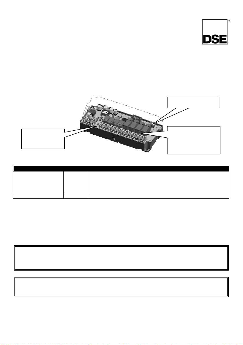
Controls and indications
ID Switch
Power on /
Link lost LED
8 x Status LED
(1 LED per
relay)
LED Indications
Function Colour Action
Power on / Link lost RED Steady when DC supply is connected and data is being received
Status 1-8 RED Lit when the corresponding relay is active
from the host controller.
Flashing when the DC supply is connected and the data
connection to the host controller is not operating.
ID switch
The rotary ID switch is used to select the ‘ID’ of the 2157 expansion module as the host controller is
capable of giving instructions to a number of 2157 expansion modules at the same time (consult
relevant modules instructions for further details on number of supported expansion units).
The enclosure cover must be unclipped and removed to gain access to the switch. The switch should
be operated using a small screwdriver and set to match the required ID.
NOTE : The ID must be a unique number, different from the ID of any other 2157 module
connected to the host controller.
If two or more 2157 controllers are required to ‘mimic’ each other then they should be
configured with different IDs, and both configured the same in the host controller.
NOTE : The selection of the ID of other types of expansion modules WILL NOT interfere/clash
with the ID of the 2548. For instance if the 2548 is set to ID 4, it is acceptable to have a different
type of expansion module (for instance 2130) set to ID 4 also.
Page 2
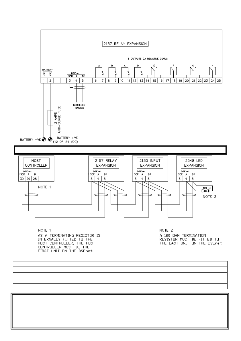
Typical wiring diagrams
Web:
www.deepseaplc.com
NOTE : Configuration of the outputs is performed in the host controller.
Dimensions
Overall size 164.6mm x 76.4mm x 48.9mm (6.48” x 3.01” x 1.93”)
Mounting type DIN rail or chassis mounting
Din rail type EN 50022 35mm type only
Mounting holes M4 clearance
Mounting hole centres 152.37mm x 64.50mm (6.00” x 2.54”)
Deep Sea Electronics Plc.
LO CALL (from UK BT landlines) :
Telephone 0845 260 8900
Email: sales@deepseaplc.com
Tel:+44 (0)1723 890099
Fax: +44 (0)1723 893303
Deep Sea Electronics Inc.
Phone: +1 (815) 316-8706
Fax: +1 (815) 316- 8708
TOLL FREE (USA only) : Tel: 1 866 636 9703
Email: sales@deepseausa.com
Web: www.deepseausa.com
Deep Sea Electronics Plc.
(Far East)
Tel:+66 2 670 6228
Fax: +66 2 678 3028
Email: sales@deepseaplc.com
Web: www.deepseaplc.com
 Loading...