

Page 1
Interior hydraulic module
MIT iSystem
EN
User Guide
300028952-001-01
Page 2

Contents
1 Introduction ................................................................................................4
1.1 Symbols used .......................................................4
1.1.1 Symbols used in the manual ...................................4
1.1.2 Symbols used on the equipment .............................4
1.2 Abbreviations ........................................................5
1.3 General ..................................................................5
1.3.1 Manufacturer's liability .............................................5
1.3.2 Installer's liability .....................................................6
1.3.3 User's liability ..........................................................6
1.4 Homologations ......................................................6
1.4.1 Certifications ...........................................................6
2 Safety instructions and recommendations ..............................................7
2.1 Safety instructions ...............................................7
2.2 Recommendations ................................................7
3 Description ..................................................................................................8
3.1 General description ..............................................8
3.2 Control panel .........................................................8
3.2.1 Description of the keys ............................................8
3.2.2 Description of the display ........................................9
3.2.3 Browsing in the menus ..........................................12
4 Operating the appliance ..........................................................................14
4.1 Putting the appliance into operation ................14
4.2 Reading out measured values ...........................15
4.3 Changing the settings ........................................16
4.3.1 Setting the set point temperatures ........................16
4.3.2 Selecting the operating mode ...............................17
4.3.3 Forcing domestic hot water production .................18
4.3.4 Setting the contrast and lighting on the
display ...................................................................18
4.3.5 Setting the time and date ......................................19
4.3.6 Selecting a timer programme ................................19
4.3.7 Customising a timer programme ...........................20
1
24/05/2012 - 300028952-001-01
Page 3

Contents
4.4 Installation shutdown .........................................22
4.5 Turning on the antifreeze function ....................22
5 Troubleshooting .......................................................................................23
5.1 Anti-hunting ........................................................23
5.2 Messages .............................................................23
5.3 Faults (Code type Lxx or Dxx) ...........................26
6 Technical specifications ..........................................................................28
6.1 Technical specifications ....................................28
6.1.1 Electricity supply ...................................................28
7 Energy savings .........................................................................................29
7.1 Energy savings ...................................................29
7.1.1 Energy-saving advice ............................................29
7.1.2 Room thermostat and settings ..............................29
7.2 Recommendations ..............................................29
8 Warranty ....................................................................................................31
8.1 General ................................................................31
8.2 Warranty terms ...................................................31
2
24/05/2012 - 300028952-001-01
Page 4

3
24/05/2012 - 300028952-001-01
Page 5
1 2
M002628-A
MIT iSystem 1. Introduction
1 Introduction
1.1 Symbols used
1.1.1. Symbols used in the manual
In these instructions, various danger levels are employed to draw the
user's attention to particular information. In so doing, we wish to
safeguard the user's safety, obviate hazards and guarantee correct
operation of the appliance.
DANGER
Risk of a dangerous situation causing serious physical
injury.
WARNING
Risk of a dangerous situation causing slight physical
injury.
CAUTION
Risk of material damage.
Signals important information.
¼ Signals a referral to other instructions or other pages in the
instructions.
1.1.2. Symbols used on the equipment
Disconnect the mains power prior to any operations.
24/05/2012 - 300028952-001-01
Before installing and commissioning the device, read
carefully the instruction manuals provided.
Dispose of the used products in an appropriate recovery
and recycling structure.
4
Page 6

1. Introduction
1.2 Abbreviations
MIT iSystem
4 DHW: Domestic hot water
4 PPS: Polypropylene hardly inflammable
4 PCU: Primary Control Unit - PCB contoller for heat pump operation
4 PSU: Parameter Storage Unit - Parameter storage for PCBs
PCU and SU
4 SCU: Secondary Control Unit - DIEMATIC iSystem control panel
PCB
4 SU: Safety Unit - Safety PCB
4 3WV: 3-way valve
4 EVU: Power supply company
4 MIT: Indoor module fitted with a DIEMATIC iSystem control panel
4 HP or PAC: Heat pump
4 EER: Frigorific efficiency ratio
4 COP: Performance coefficient
1.3 General
4 Supply temperature: Temperature of the water circulating in the
radiators or in the underfloor heating.
4 Ambient temperature: Temperature inside the house or in a room.
4 Room temperature instruction: Temperature programmed in the
control system that must be reached by the heat pump.
1.3.1. Manufacturer's liability
Our products are manufactured in compliance with the requirements
of the various applicable European Directives. They are therefore
delivered with [ marking and all relevant documentation.
In the interest of customers, we are continuously endeavouring to
make improvements in product quality. All the specifications stated in
this document are therefore subject to change without notice.
Our liability as the manufacturer may not be invoked in the following
cases:
4 Failure to abide by the instructions on using the appliance.
4 Faulty or insufficient maintenance of the appliance.
4 Failure to abide by the instructions on installing the appliance.
5
24/05/2012 - 300028952-001-01
Page 7

MIT iSystem
1. Introduction
1.3.2. Installer's liability
The installer is responsible for the installation and inital start up of the
appliance. The installer must respect the following instructions:
4 Read and follow the instructions given in the manuals provided
with the appliance.
4 Carry out installation in compliance with the prevailing legislation
and standards.
4 Perform the initial start up and carry out any checks necessary.
4 Explain the installation to the user.
4 If a maintenance is necessary, warn the user of the obligation to
check the appliance and maintain it in good working order.
4 Give all the instruction manuals to the user.
1.3.3. User's liability
To guarantee optimum operation of the appliance, the user must
respect the following instructions:
1.4 Homologations
4 Read and follow the instructions given in the manuals provided
with the appliance.
4 Call on qualified professionals to carry out installation and initial
start up.
4 Get your installer to explain your installation to you.
4 To carry out inspections and maintenance required by a qualified
professional.
4 Keep the instruction manuals in good condition close to the
appliance.
This appliance is not intended to be used by persons (including
children) whose physcial, sensory or mental capacity is impaired or
persons with no experience or knowledge, unless they have the
benefit, through the intermediary of a person responsible for their
safety, of supervision or prior instructions regarding use of the
appliance. Care should be taken to ensure that children do not play
with the appliance.
1.4.1. Certifications
24/05/2012 - 300028952-001-01
This product complies to the requirements to the european directives
and following standards:
4 2006/95/EC Low Voltage Directive. Reference Standards:
EN60335-1 / EN60335-2-40.
4 2004/108/EC Electromagnetic Compatibility Directive. Generic
standards: EN1000-6-3 , EN 61000-6-1.
6
Page 8
2. Safety instructions and recommendations
2 Safety instructions and
recommendations
2.1 Safety instructions
DANGER
If smoke is released or in case of refrigerant leak:
1. Switch the appliance off.
2. Open the windows.
3. Evacuate the premises.
4. Contact a qualified professional.
MIT iSystem
2.2 Recommendations
CAUTION
Do not neglect to service the appliance. Contact a qualified
professional or take out a maintenance contract for the
annual servicing of the appliance.
WARNING
Only qualified professionals are authorised to work on the
appliance and the installation.
4 Regularly check that the water pressure in the installation is
between 1,5 and 2 bar.
4 Ensure that the appliance is accessible at all times for
maintenance purposes.
4 Avoid draining the installation.
4 Use only original spare parts.
4 Never remove or cover labels and rating plates affixed to the
appliance. Labels and rating plates must be legible throughout the
entire lifetime of the appliance.
7
24/05/2012 - 300028952-001-01
Page 9
M002616-A
bar
STD
0 2 4 6 8 10 12 14 16 18 22 2420
b
v
AUTO
g
A
B
C
D
E
F
w
1
1
2
MIT iSystem 3. Description
3 Description
3.1 General description
The MIT module is fitted with a DIEMATIC iSystem control panel with
integrated regulator. It handles the automatic operation of the heat
pump as a function of:
4 The outside temperature.
4 The ambient temperature when the remote control (as an option)
is connected.
The DIEMATIC iSystem control panel enables:
4 The independent control of a direct circuit without mixing valve and
a circuit with mixing valve.
4 The independent control system on a DHW preparation circuit.
4 Anti-freeze protection for the installation and the environment if the
home is empty (This period may be programed up to 99 days).
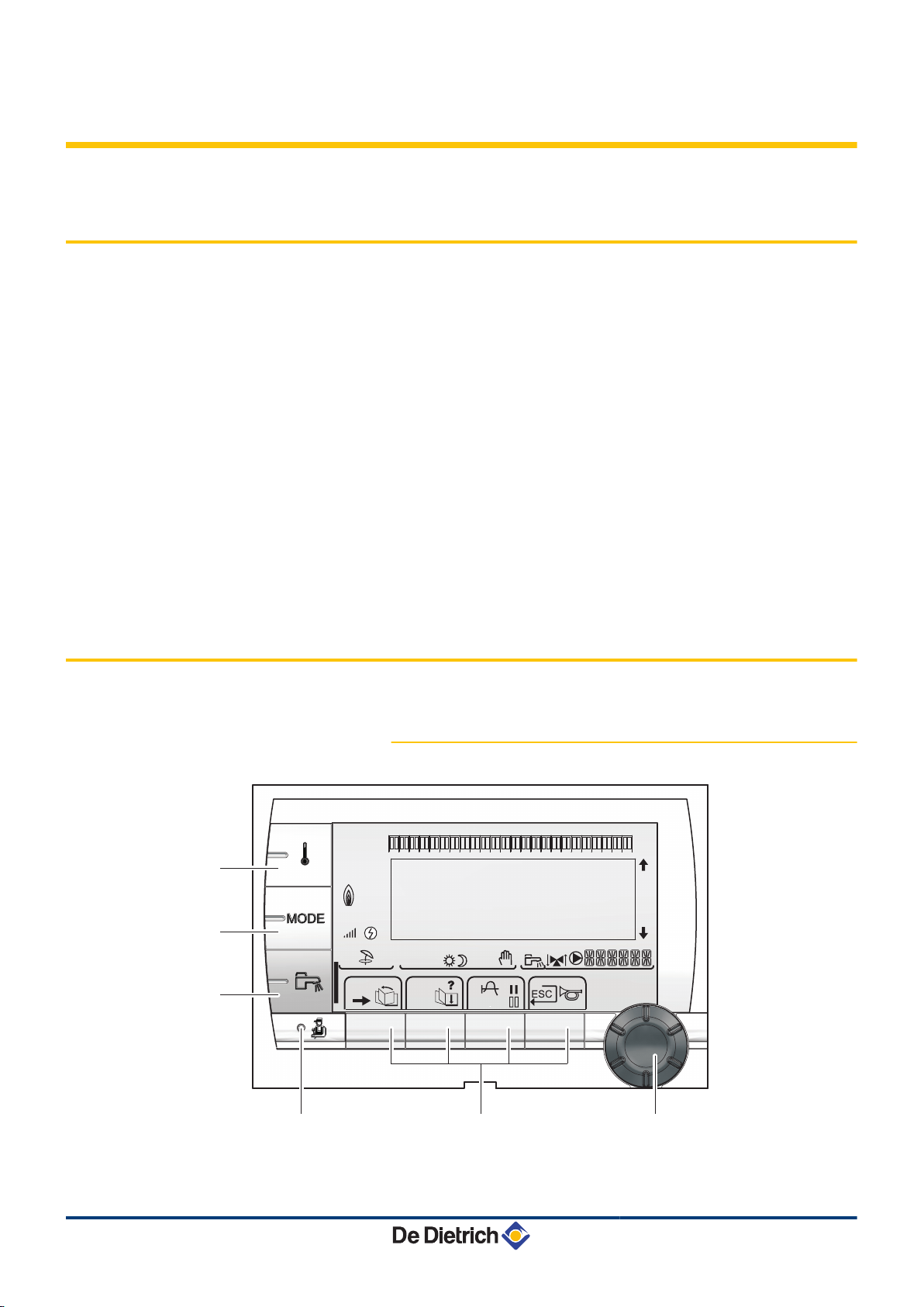
3.2 Control panel
The MIT module also integrates the 30-litre buffer / pressure release
tank and additional electrical heating (Only MIT/E).
3.2.1. Description of the keys
24/05/2012 - 300028952-001-01
A
Temperature setting key (heating, DHW, swimming pool)
8
Page 10
L000200-A
L000201-A
L000198-A
L000199-A
bar
r
STD
(
'
t
0 2 4 6 8 10 12 14 16 18 22 2420
C002696-A
p
b
AUTO
x
c
r
j
L
g
m
bar
STD
t
0 2 4 6 8 10 12 14 16 18 22 2420
L000197-A
p
b
AUTO
x
c
r
j
M
g
m
3. Description MIT iSystem
B
C
D
E
Operating mode selection key
DHW override key
Key to access the parameters reserved for the installer
Keys on which the function varies as and when selections
are made
¼ See: "Key functions", page 9
F
Rotary setting button:
4 Turn the rotary button to scroll through the menus or
modify a value
4 Press the rotary button to access the selected menu
or confirm a value modification
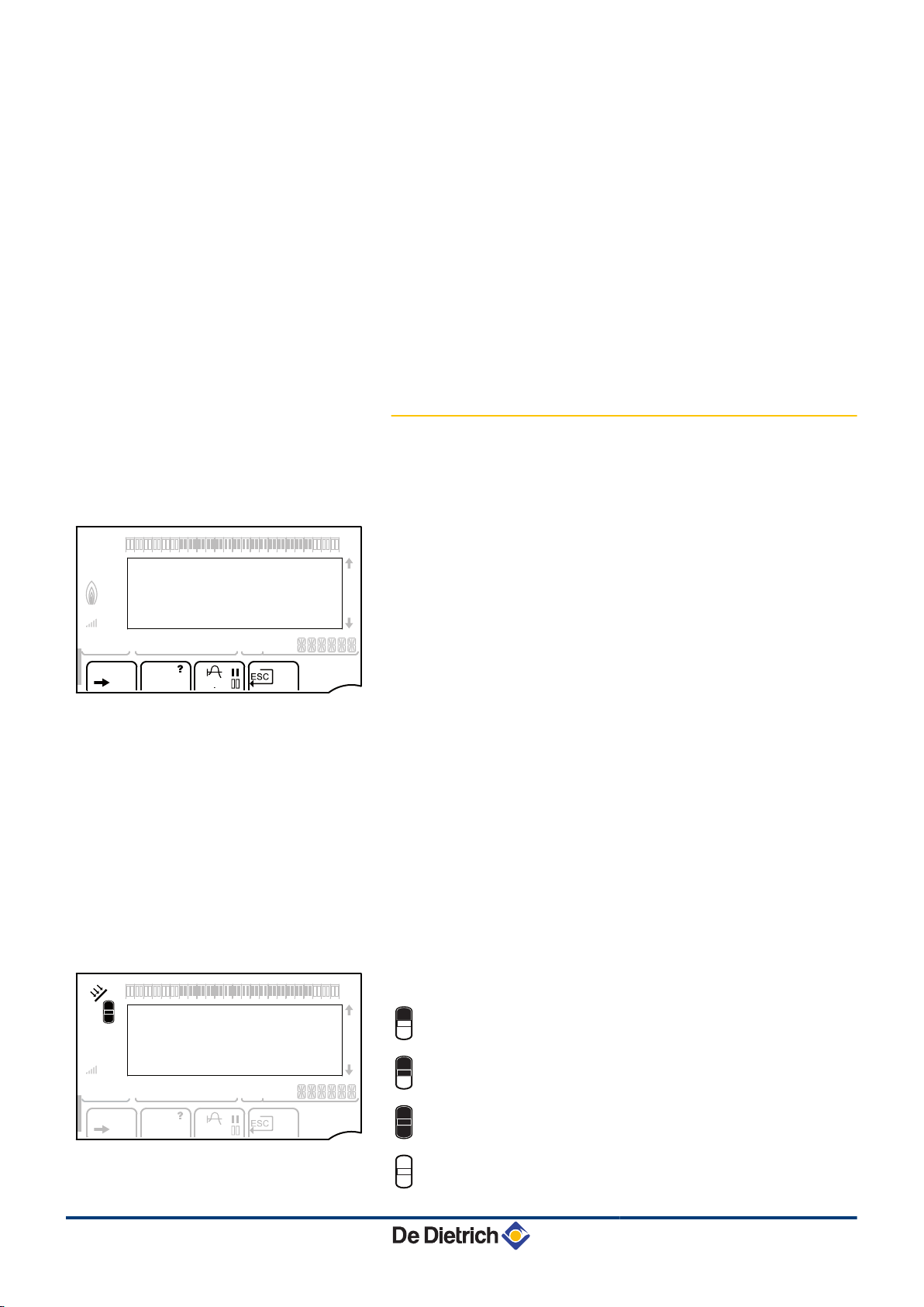
3.2.2. Description of the display
Key functions
n
>
(
'
?
Access to the various menus
Used to scroll through the menus
Used to scroll through the parameters
The symbol is displayed when help is available
f
STD
b
Used to display the curve of the parameter selected
Reset of the time programmes
Selection of comfort mode or selection of the days to be
programmed
v
Selection of reduced mode or deselection of the days to
be programmed
j
ESC
Back to the previous level
Back to the previous level without saving the
modifications made
t
Solar (If connected)
n
u
Manual reset
The solar load pump is running
The top part of the tank is reheated to the tank set point
The entire tank is reheated to the tank set point
9
The entire tank is reheated to the solar tank set point
The tank is not loaded - Presence of the solar control
system
24/05/2012 - 300028952-001-01
Page 11
bar
1
1
2
c
STD
t
v
0 2 4 6 8 10 12 14 16 18 22 2420
M002620-A
p
b
w
AUTO
x
c
r
j
M
g
m
bar
STD
t
0 2 4 6 8 10 12 14 16 18 22 2420
C002698-B
p
b
AUTO
x
c
r
j
M
g
m
bar
STD
t
0 2 4 6 8 10 12 14 16 18 22 2420
C002708-A
p
b
AUTO
x
c
r
j
M
g
m
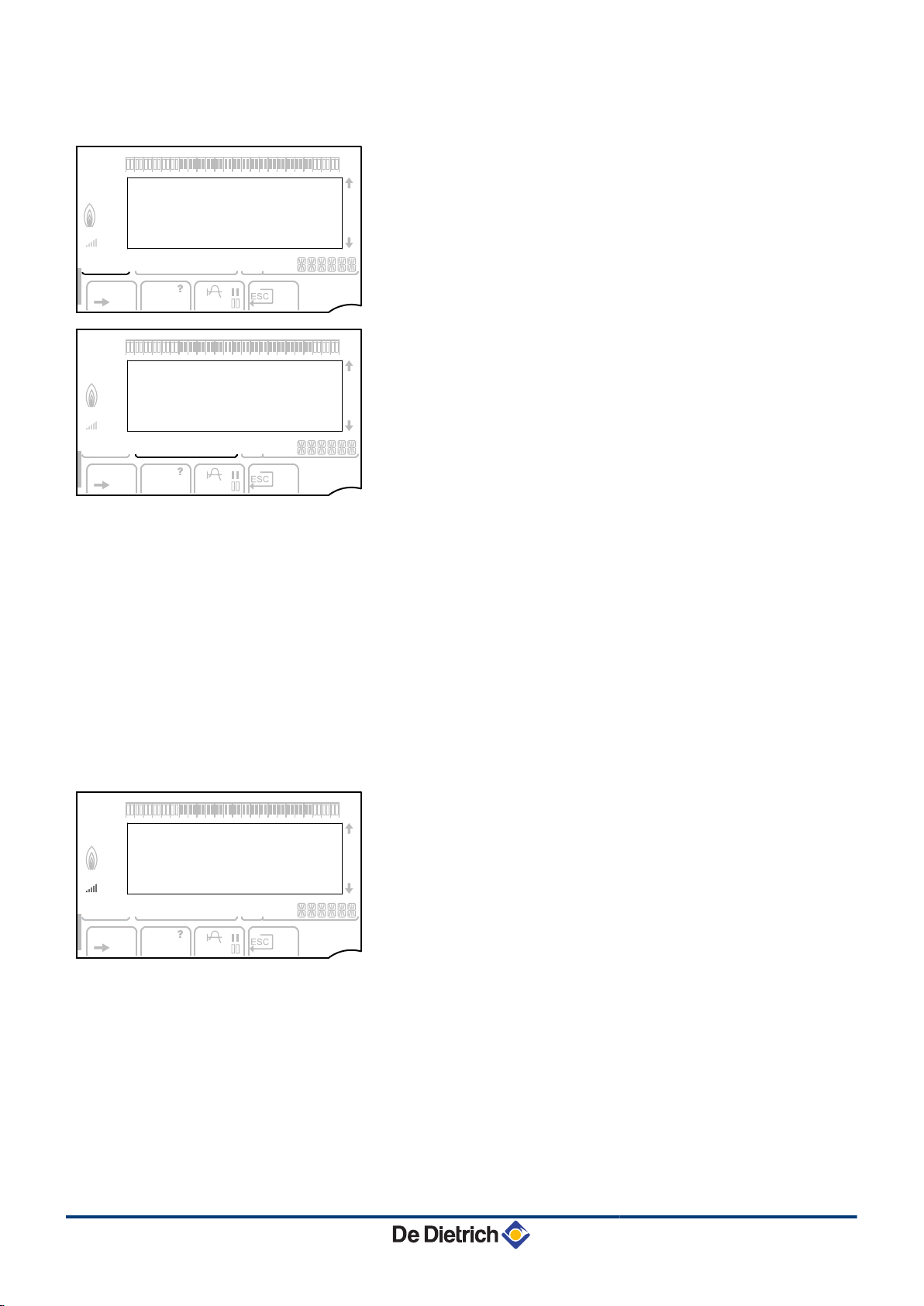
MIT iSystem 3. Description
Operating modes
n
p
b
w + p
w
AUTO
x
m
g
Summer mode: Cooling is possible. Domestic hot water
continues to be produced.
WINTER mode: Heating and domestic hot water working.
Forced cooling mode.
Cooling mode: Heating according to the time programme.
Operation in automatic mode according to the timer
programme.
Comfort mode: The symbol is displayed when a DAY
override (comfort) is activated.
4 Flashing symbol: Temporary override
4 Steady symbol: Permanent override
Reduced mode: The symbol is displayed when a NIGHT
override (reduced) is activated.
4 Flashing symbol: Temporary override
4 Steady symbol: Permanent override
Holiday mode: The symbol is displayed when a HOLIDAY
override (antifreeze) is activated.
4 Flashing symbol: Holiday mode programmed
4 Steady symbol: Holiday mode active
m
System pressure
n
bar
Manual mode
Pressure indicator: The symbol is displayed when a water
pressure sensor is connected.
4 Flashing symbol: The water pressure is insufficient.
4 Steady symbol: The water pressure is sufficient.
l
Water pressure level
4 R : 0,9 to 1,1 bar
4 E : 1,2 to 1,5 bar
4 Z : 1,6 to 1,9 bar
4 A : 2,0 to 2,3 bar
4 l : > 2,4 bar
24/05/2012 - 300028952-001-01
10
Page 12

bar
STD
t
0 2 4 6 8 10 12 14 16 18 22 2420
C002707-A
p
b
AUTO
x
c
r
j
M
g
m
bar
1
1
2
c
STD
t
v
0 2 4 6 8 10 12 14 16 18 22 2420
M002630-A
p
b
w
AUTO
x
c
r
j
M
g
m
bar
1
1
2
c
STD
t
v
0 2 4 6 8 10 12 14 16 18 22 2420
M002632-A
p
b
w
AUTO
x
c
r
j
M
g
m
bar
1
1
2
c
STD
t
v
0 2 4 6 8 10 12 14 16 18 22 2420
M002631-A
p
b
w
AUTO
x
c
r
j
M
g
m
3. Description MIT iSystem
Domestic Hot Water override
n
A bar is displayed when a DHW override is activated:
4 Flashing bar: Temporary override
4 Steady bar: Permanent override
Electrical back-up
n
G
The symbol 1 or 2 lights up, depending on whether stage
1 or 2 on the electrical back-up is commanded.
Hydraulic additional heating
n
y
4 Steady symbol: The burner and the heating pump on
the back-up boiler are commanded.
4 Flashing symbol: The heating pump on the back-up
boiler is commanded.
Status of the compressor
n
11
v
4 Steady symbol: The compressor is running.
4 Flashing symbol: The heat pump is required but the
compressor is off.
24/05/2012 - 300028952-001-01
Page 13

bar
STD
t
0 2 4 6 8 10 12 14 16 18 22 2420
C002699-B
p
b
AUTO
x
c
r
j
M
g
m
bar
1
1
2
2
r
c
STD
(
'
t
v
0 2 4 6 8 10 12 14 16 18 22 2420
p
b
AUTO
x
c
r
j
L
g
m
#MEASURES
#CHOICE TIME PROG.
#TIME PROGRAM
#SETTING
#TIME .DAY
a
C002220-B-04
bar
1
1
2
2
r
c
STD
(
'
t
v
0 2 4 6 8 10 12 14 16 18 22 2420
p
b
AUTO
x
c
r
j
L
g
m
CURRENT PROG.B
CURRENT PROG.C
P2
P3
a
C002221-C-04
bar
1
1
2
2
r
c
STD
(
'
t
v
0 2 4 6 8 10 12 14 16 18 22 2420
p
b
AUTO
x
c
r
j
L
g
m
CURRENT PROG.C
"Choice of the timeprogram
applied C"
P4
a
C002222-C-04
MIT iSystem 3. Description
Other information
n
r
The symbol is displayed when domestic hot water
production is running.
w
Valve indicator: The symbol is displayed when a 3-way
valve is connected.
4 x : 3-way valve opens
4 c : 3-way valve closes
M
The symbol is displayed when the pump is operating.
Name of the circuit for which the parameters are
displayed.
3.2.3. Browsing in the menus
1. To select the desired menu, turn the rotary button.
2. To access the menu, press the rotary button.
To go back to the previous display, press the key j.
3. To select the desired parameter, turn the rotary button.
4. To modify the parameter, press the rotary button.
To go back to the previous display, press the key j.
5. To modify the parameter, turn the rotary button.
6. To confirm, press the rotary button.
To cancel, press key
h
.
24/05/2012 - 300028952-001-01
12
Page 14

bar
1
1
2
2
r
c
STD
(
'
t
v
0 2 4 6 8 10 12 14 16 18 22 2420
p
b
AUTO
x
c
r
j
M
g
m
LUNDI 11:45
C002224-D-04
2x
3. Description MIT iSystem
7. To go back to the main display, press key j2 times.
It is possible to use the ( and ' keys instead of the rotary
button.
13
24/05/2012 - 300028952-001-01
Page 15

C002366-B
Français - Deutsch - English Italiano - Espanol - Nederlands
- Pycck - Polski - Türk -
bar
1
1
2
2
r
c
STD
(
'
t
v
0 2 4 6 8 10 12 14 16 18 22 2420
p
b
x
c
r
g
m
ÿ
LANGUE FRANCAIS
C002286-C
MIT iSystem
4 Operating the appliance
4.1 Putting the appliance into operation
1. Switch on the power by throwing the on/off switch on the inside
module.
2. The first time the boiler is powered up, the LANGUAGE menu is
displayed. Select the desired language by turning the rotary
button.
3. To confirm, press the rotary button.
4. The parameter TYPE displays. Select the type of thermodynamic
unit by turning the rotary button.
4. Operating the appliance
Indoor module
MIT/E ROE-II
MIT/H ROE-II
Outside module TYPE
ROE-II E FR
ROE-H
ROE+
ROE+TH
ROI+
ROE-H E
ROE+ E FR
ROE+TH E
ROI+ E FR
ROE-II H FR
ROE-H
ROE+
ROE+TH
ROI+
ROE-H H
ROE+ H FR
ROE+TH H
ROI+ H FR
Error during the start-up procedure:
4 No information is shown on the display:
Contact the professional who takes care of maintenance of the
appliance.
4 If there is a problem, the error is displayed on the screen.
¼ See chapter: "Messages", page 23.
24/05/2012 - 300028952-001-01
14
Page 16

bar
1
1
2
2
r
c
STD
(
'
t
v
0 2 4 6 8 10 12 14 16 18 22 2420
p
b
AUTO
x
c
r
j
M
g
m
SUNDAY 11:45
C002219-D-04
4. Operating the appliance MIT iSystem
4.2 Reading out measured values
The various values measured by the appliance are displayed in the
#MEASURES menu.
1. To access user level: Press the > key.
2. Select the menu #MEASURES.
4 Turn the rotary button to scroll through the menus or
modify a value.
4 Press the rotary button to access the selected menu
or confirm a value modification.
For a detailed explanation of menu browsing, refer
¼
to the chapter: "Browsing in the menus", page 12.
User level - Menu #MEASURES
Parameter Description Unit ROE-II ROE-H ROE+ ROE+TH ROI+
OUTSIDE TEMP.
ROOMTEMP. A
ROOMTEMP. B
ROOMTEMP. C
TEMP.MIT
PRESSURE
WATER TEMP.
STOR.TANK.TEMP
(1)
SWIMMING P.T.B
SWIMMING P.T.C
OUTLET TEMP. B
OUTLET TEMP. C
SYSTEM TEMP.
T.DHW BOTTOM
TEMP.TANK AUX
DHW A TEMP.
(1)
TEMP.SOL.TANK
SOLAR.COLL.T.
SOLA.ENERGY
HP OUTSIDE T.
TEMP.DEPART HP Heat pump flow temperature °C x x x x x
HP RETURN TEMP
COLD TEMP.
SOURCE TEMP. Refrigerant temperature at the heat pump source end °C
EVAPORATOR T.
FLUID EVAP.T.
FLUID COND.T.
(1) The parameter is only displayed for the options, circuits or sensors actually connected.
15
Outside temperature °C x x x x x
(1)
Room temperature of circuit A °C x x x x x
(1)
Room temperature of circuit B °C x x x x x
(1)
Room temperature of circuit C °C x x x x x
Inside module flow sensor measurement °C x x x x x
Water pressure in the installation bar x x x x x
(1)
Water temperature in the DHW tank °C x x x x x
Water temperature in the storage tank °C x x x x x
(1)
Water temperature of the swimming pool on circuit B °C x x x x x
(1)
Water temperature of the swimming pool on circuit C °C x x x x x
(1)
Temperature of the flow water in circuit B °C x x x x x
(1)
Temperature of the flow water in circuit C °C x x x x x
(1)
Temperature of the system flow water if multi-
°C x x x x x
generator
(1)
Water temperature in the bottom of the DHW tank °C x x x x x
(1)
Water temperature in the second DHW tank
°C x x x x x
connected to the AUX circuit
Water temperature in the second DHW tank
°C x x x x x
connected to circuit A
(1)
Temperature of the hot water produced by solar power
°C x x x x x
(TS)
(1)
Solar panel temperature (TC) °C x x x x x
(1)
Solar energy accumulated in the tank kWh x x x x x
Outside temperature measured by the heat pump °C x x x x x
Return temperature °C x x
Temperature of the heat pump cold circuit °C
x
Refrigerant temperature at the fin tube exchanger
outlet
Fin tube exchanger refrigerant temperature °C x x
Refrigerant temperature at the heat exchanger °C x x
°C
24/05/2012 - 300028952-001-01
x
x x
Page 17

MODE
C002266-A
MIT iSystem 4. Operating the appliance
User level - Menu #MEASURES
Parameter Description Unit ROE-II ROE-H ROE+ ROE+TH ROI+
HOT GAS TEMP.
HOT GAS TEMP.
NB IMPULS.COMP
NB IMPULS.COMP.1
RUNTIME HP
NB IMPULS.COMP.2
RUNTIME.COMP.2
IN 0-10V
SEQUENCE
CTRL Software control number (SCU)
(1) The parameter is only displayed for the options, circuits or sensors actually connected.
(1)
Refrigerant temperature at the compressor outlet °C
Compressor outlet temperature °C
Number of heat pump start-ups
Number of start-ups on compressor 1
Number of hours' operation of the heat pump
compressor
Number of start-ups on compressor 2
Number of hours' operation of compressor 2 h
Voltage at input 0-10 V V x x x x x
Control system sequence
x x x
h x x x x x
x x x x x
x x x x x
x
x
x
x
x
x
4.3 Changing the settings
4.3.1. Setting the set point temperatures
To set the various heating, DHW and swimming pool temperatures,
proceed as follows:
1. Press the C key.
2. To select the desired parameter, turn the rotary button.
3. To modify the parameter, press the rotary button.
To go back to the previous display, press the key j.
4. To modify the parameter, turn the rotary button.
5. To confirm, press the rotary button.
To cancel, press key
Menu C
Parameter Adjustment range Description Factory setting
DAY TEMP. A
NIGHT TEMP. A
ROOMTEM.COOL A
DAY TEMP. B
NIGHT TEMP. B
ROOMTEM.COOL B
DAY TEMP. C
NIGHT TEMP. C
ROOMTEM.COOL C
WATER TEMP.
(1) The parameter is only displayed if the corresponding circuit can handle cooling.
(2) The parameter is only displayed for the options, circuits or sensors actually connected.
(2)
(2)
(2)
(2)
(2)
5 to 30 °C Desired room temperature in comfort periods on circuit A 20 °C
5 to 30 °C Desired room temperature in reduced periods on circuit A 16 °C
(1) (2)
22 to 30 °C Desired room temperature set point in cooling mode 25 °C
5 to 30 °C Desired room temperature in comfort periods on circuit B 20 °C
5 to 30 °C Desired room temperature in reduced periods on circuit B 16 °C
(2) (1)
22 to 30 °C Desired room temperature set point in cooling mode 25 °C
5 to 30 °C Desired room temperature in comfort periods on circuit C 20 °C
5 to 30 °C Desired room temperature in reduced periods on circuit C 16 °C
(2) (1)
22 to 30 °C Desired room temperature set point in cooling mode 25 °C
10 to 65 °C Desired domestic hot water temperature in the DHW circuit 55 °C
h
.
24/05/2012 - 300028952-001-01
16
Page 18

MODE
C002267-A
4. Operating the appliance MIT iSystem
Menu C
Parameter Adjustment range Description Factory setting
TEMP.TANK AUX
DHW A TEMP.
WATER T.NIGHT
(2)
(2)
(2)
AUX.TANK T.NIGHT
A.TANK T.NIGHT
TEMP.SOL.TANK
SWIMMING P.T.B
SWIMMING P.T.C
(1) The parameter is only displayed if the corresponding circuit can handle cooling.
(2) The parameter is only displayed for the options, circuits or sensors actually connected.
(2)
(2)
(2)
(2)
10 to 80 °C
10 to 80 °C Desired domestic hot water temperature in circuit A 55 °C
10 to 80 °C Desired temperature of the domestic hot water in night mode 55 °C
(2)
10 to 80 °C Desired temperature of the domestic hot water in night mode 55 °C
10 to 80 °C Desired temperature of the domestic hot water in night mode 55 °C
10 to 80 °C Temperature of the hot water produced by solar power (TS) 55 °C
5 to 39 °C Desired temperature for swimming pool B 20 °C
5 to 39 °C Desired temperature for swimming pool C 20 °C
Desired domestic hot water temperature in the auxiliary
circuit
55 °C
4.3.2. Selecting the operating mode
To select an operating mode, proceed as follows:
1. Press the MODE key.
2. To select the desired parameter, turn the rotary button.
3. To modify the parameter, press the rotary button.
To go back to the previous display, press the key j.
4. To modify the parameter, turn the rotary button.
5. To confirm, press the rotary button.
To cancel, press key
h
.
Menu MODE
Parameter Adjustment range Description Factory setting
AUTOMATIQUE
DAY
7/7, xx:xx Comfort mode is forced until the time indicated or all the time (7/7). Present time + 1
The comfort ranges are determined by the timer programme.
hour
NIGHT
HOLIDAYS
SUMMER
7/7, xx:xx Reduced mode is forced until the time indicated or all the time
(7/7).
7/7, 1 to 365 The antifreeze mode is active on all boiler circuits.
Number of days' holiday: xx
heating OFF: xx:xx
Restarting: xx:xx
The heating is off.
(1)
(1)
(1)
Present time + 1
hour
Present date + 1
day
Domestic hot water continues to be produced.
COLD
MANUEL
Cooling mode is forced.
The generator operates according to the set point setting. All of
the pumps operate. Option of setting the set point by simply
turning the rotary button.
FORCE AUTO
YES / NO An operating mode override is activated on the remote control
(2)
(option).
To force all circuits to run on AUTOMATIQUE mode, select
(1) The start and end days and the number of days are calculated in relation to each other.
(2) The parameter is only displayed if a room sensor is connected.
YES.
17
24/05/2012 - 300028952-001-01
Page 19

MODE
C002268-A
bar
1
1
2
2
r
c
STD
(
'
t
v
0 2 4 6 8 10 12 14 16 18 22 2420
p
b
AUTO
x
c
r
j
M
g
m
SUNDAY 11:45
C002219-D-04
MIT iSystem 4. Operating the appliance
4.3.3. Forcing domestic hot water production
To force domestic hot water production, proceed as follows:
1. Press the r key.
2. To select the desired parameter, turn the rotary button.
3. To modify the parameter, press the rotary button.
To go back to the previous display, press the key j.
4. To modify the parameter, turn the rotary button.
5. To confirm, press the rotary button.
To cancel, press key
h
.
Menu r
Parameter Description Factory setting
AUTOMATIQUE
COMFORT
The domestic hot water comfort ranges are determined by the timer programme.
Domestic hot water comfort mode is forced until the time indicated or all the time (7/7). Present time + 1 hour
4.3.4. Setting the contrast and lighting on the
display
1. To access user level: Press the > key.
2. Select the menu #SETTING.
4
Turn the rotary button to scroll through the menus or
modify a value.
4 Press the rotary button to access the selected menu
or confirm a value modification.
For a detailed explanation of menu browsing, refer
¼
to the chapter: "Browsing in the menus", page 12.
3. Set the following parameters:
User level - Menu #SETTING
Parameter Adjustment range Description Factory setting Customer setting
CONTRAST DISP.
BACK LIGHT COMFORT
ECO
24/05/2012 - 300028952-001-01
Adjusting the display contrast.
The screen is illuminated continuously in
daytime periods.
The screen is illuminated for 2 minutes
whenever pressed.
ECO
18
Page 20

bar
1
1
2
2
r
c
STD
(
'
t
v
0 2 4 6 8 10 12 14 16 18 22 2420
p
b
AUTO
x
c
r
j
M
g
m
SUNDAY 11:45
C002219-D-04
bar
1
1
2
2
r
c
STD
(
'
t
v
0 2 4 6 8 10 12 14 16 18 22 2420
p
b
AUTO
x
c
r
j
M
g
m
SUNDAY 11:45
C002219-D-04
4. Operating the appliance
4.3.5. Setting the time and date
1. To access user level: Press the > key.
2. Select the menu #TIME .DAY.
4 Turn the rotary button to scroll through the menus or
modify a value.
4 Press the rotary button to access the selected menu
or confirm a value modification.
For a detailed explanation of menu browsing, refer
¼
to the chapter: "Browsing in the menus", page 12.
3. Set the following parameters:
MIT iSystem
User level - Menu #TIME .DAY
(1)
Parameter Adjustment range Description Factory setting Customer setting
HOURS
MINUTE
DAY
DATE
MONTH
YEAR
SUM. TIME: AUTO
0 to 23 Hours setting
0 to 59 Minutes setting
Monday to Sunday Setting the day of the week
1 to 31 Day setting
January to December Month setting
2008 to 2099 Year setting
automatic switch to summer time on the last Sunday
AUTO
in March and back to winter time on the last Sunday
in October.
MANU
for countries where the time change is done on
other dates or is not in use.
(1) According to the configuration
4.3.6. Selecting a timer programme
1. To access user level: Press the > key.
2. Select the menu #CHOICE TIME PROG..
19
4
Turn the rotary button to scroll through the menus or
modify a value.
4 Press the rotary button to access the selected menu
or confirm a value modification.
For a detailed explanation of menu browsing, refer
¼
to the chapter: "Browsing in the menus", page 12.
3. To select the desired parameter.
4. Assign the desired timer programme (P1 to P4) to the circuit with
the rotary button.
24/05/2012 - 300028952-001-01
Page 21

bar
1
1
2
2
r
c
STD
(
'
t
v
0 2 4 6 8 10 12 14 16 18 22 2420
p
b
AUTO
x
c
r
j
M
g
m
SUNDAY 11:45
C002219-D-04
bar
1
1
2
2
r
c
STD
(
'
t
v
0 2 4 6 8 10 12 14 16 18 22 2420
p
b
AUTO
x
c
r
j
L
g
m
PROG P2 C
Mo Tu We Th Fr Sa Su
"Display of the timeprogram.
To continuepush on the button"
a
C002228-B-04
MIT iSystem
4. Operating the appliance
User level - Menu #CHOICE TIME PROG.
Parameter Adjustment range Description
CURRENT PROG.A
P1 / P2 / P3 / P4 Comfort programme activated
(Circuit A)
CURRENT PROG.B
P1 / P2 / P3 / P4 Comfort programme activated
(Circuit B)
CURRENT PROG.C
P1 / P2 / P3 / P4 Comfort programme activated
(Circuit C)
4.3.7. Customising a timer programme
1. To access user level: Press the > key.
2. Select the menu #TIME PROGRAM.
4 Turn the rotary button to scroll through the menus or
modify a value.
4 Press the rotary button to access the selected menu
or confirm a value modification.
For a detailed explanation of menu browsing, refer
¼
to the chapter: "Browsing in the menus", page 12.
3. To select the desired parameter.
User level - Menu #TIME PROGRAM
Parameter Time schedule Description
TIME PROG.A PROG P2 A
Timer programme for circuit A
PROG P3 A
PROG P4 A
TIME PROG.B PROG P2 B
Timer programme for circuit B
PROG P3 B
PROG P4 B
TIME PROG.C PROG P2 C
Timer programme for circuit C
PROG P3 C
PROG P4 C
TIME PROG.DHW
TIME PROG.AUX
EVU TIMER PROG.
DHW circuit timer programme
Auxiliary circuit timer programme
EVU power cut off timer program
4. To select a timer programme to be modified.
To select to days for which the timer programme is to be
5.
modified:
Turn the rotary button to the left until you reach the day desired.
To confirm, press the rotary button.
24/05/2012 - 300028952-001-01
20
Page 22

bar
1
1
2
2
r
c
STD
(
'
t
v
0 2 4 6 8 10 12 14 16 18 22 2420
p
b
AUTO
x
c
r
j
L
g
m
PROG P2 C
Mo Tu
We Th Fr Sa Su
"Select the days to
program"
a
C002229-C-04
bar
1
1
2
2
r
c
STD
(
'
t
v
0 2 4 6 8 10 12 14 16 18 22 2420
p
b
AUTO
x
c
r
j
L
g
m
PROG P2 C
Mo Tu
We Th Fr Sa Su
Set the time program.
a
C002230-E-04
06:00
06:00
4. Operating the appliance MIT iSystem
6.b : Day selection
Press key b / v until the symbol b is displayed.
Turn the rotary button to the right to select the day(s) desired.
: Cancelling the day selection
v
Press key b / v until the symbol v is displayed.
Turn the rotary button to the right to cancel selection of the relevant
day(s).
7. When the days desired for the programme have been selected,
press the rotary button to confirm.
To define the timer ranges for the comfort mode and reduced
8.
mode:
Turn the rotary button to the left until 0:00 is displayed. The first
segment of the graphic bar for the timer programme flashes.
9.b : Comfort mode selection
Press key b / v until the symbol b is displayed.
To select a comfort time range, turn the rotary button to the right.
: Reduced mode selection
v
Press key b / v until the symbol v is displayed.
To select a reduced time range, turn the rotary button to the right.
10.When the times for the comfort mode have been selected, press
the rotary button to confirm.
User level - Menu #TIME PROGRAM
TIME PROG.A
Day Comfort periods / Filling enabled:
Monday 6:00 to 22:00
Tuesday 6:00 to 22:00
Wednesday 6:00 to 22:00
Thursday 6:00 to 22:00
Friday 6:00 to 22:00
Saturday 6:00 to 22:00
Sunday 6:00 to 22:00
TIME PROG.B
Monday 6:00 to 22:00
Tuesday 6:00 to 22:00
Wednesday 6:00 to 22:00
Thursday 6:00 to 22:00
Friday 6:00 to 22:00
Saturday 6:00 to 22:00
Sunday 6:00 to 22:00
TIME PROG.C
Monday 6:00 to 22:00
Tuesday 6:00 to 22:00
Wednesday 6:00 to 22:00
Thursday 6:00 to 22:00
Friday 6:00 to 22:00
Saturday 6:00 to 22:00
Sunday 6:00 to 22:00
P1
_______________
P2 _______________ P3 _______________ P4 _______________
21
24/05/2012 - 300028952-001-01
Page 23

MIT iSystem
User level - Menu #TIME PROGRAM
TIME PROG.DHW
TIME PROG.AUX
EVU TIMER PROG.
Day Comfort periods / Filling enabled:
Monday
Tuesday
Wednesday
Thursday
Friday
Saturday
Sunday
Monday
Tuesday
Wednesday
Thursday
Friday
Saturday
Sunday
Monday
Tuesday
Wednesday
Thursday
Friday
Saturday
Sunday
P1
_______________
4. Operating the appliance
P2 _______________ P3 _______________ P4 _______________
4.4 Installation shutdown
If the central heating system is not used for a long period, we
recommend switching the appliance off.
To stop the inside module, use the J/K ON/OFF switch and cut the
power supply on the house's junction box.
To shut down the outside module, switch off the power supply on the
junction box inside the house.
CAUTION
Antifreeze protection is no longer guaranteed
automatically if the mains supply is switched off.
4.5 Turning on the antifreeze function
Put the heat pump into HOLIDAYS mode. ¼ See chapter:
"Selecting the operating mode", page 17
24/05/2012 - 300028952-001-01
22
Page 24

5. Troubleshooting MIT iSystem
5 Troubleshooting
5.1 Anti-hunting
When the heat pump is in "anti-short cycle" operating mode, the
symbol "?" flashes. This is a normal operating mode. When the restart
temperature is reached, operation will be guaranteed.
1. Press the "?" key.
The message Operation assured when the restart temperature
will be reached is displayed. When the restart temperature is
reached, operation will be guaranteed.
This message is not an error message but an item of
information.
5.2 Messages
Code
Messages Description Checking / solution
B0 BL.PARAM.CRC
B1 BL.NO CONFIG
B2 BL.MIT/MHR S.
B3 BL.S.DEP.HP
In the case of failure, the control panel displays a message and a
corresponding code.
1. Make a note of the code displayed.
The code is important for the correct and rapid diagnosis of the
type of failure and for any technical assistance that may be
needed.
2. Switch off heat pump and start up again.
The heat pump starts up again autonomously when the cause of
the failure has been lifted.
3. If the code is displayed again, correct the problem by following the
instructions in the table below:
Error parameters.
The inside module has not been
configured.
The MIT flow sensor is short
circuited or on an open circuit.
Heat pump flow sensor error. Bad connection.
4 Switch off the mains supply to the installation
4 Switch back on
The PSU PCB has been changed.
4 Contact the professional who takes care of maintenance
of the appliance.
Bad connection.
4 Contact the professional who takes care of maintenance
of the appliance.
B4 BL.S.EXT.HP
B5 BL.S.RET.HP
23
4 Contact the professional who takes care of maintenance
of the appliance.
Source sensor error/heat pump
outside temperature sensor.
Heat pump return sensor error. Bad connection.
Bad connection.
4 Contact the professional who takes care of maintenance
of the appliance.
4 Contact the professional who takes care of maintenance
of the appliance.
24/05/2012 - 300028952-001-01
Page 25

MIT iSystem 5. Troubleshooting
Code Messages Description Checking / solution
B6 BL.S.ECH.HP
Heat pump exchanger sensor
error.
Bad connection.
4 Contact the professional who takes care of maintenance
of the appliance.
B7 BL.S.BAT.HP
Heat pump battery sensor error. Bad connection.
4 Contact the professional who takes care of maintenance
of the appliance.
B8 BL.BL INPUT OPEN
The BL inlet on the PCU PCB
terminal block is open. No
antifreeze protection.
The contact connected to the BL inlet is open.
4 Contact the professional who takes care of maintenance
of the appliance.
Parameter error.
4 Contact the professional who takes care of maintenance
of the appliance.
Bad connection.
4 Contact the professional who takes care of maintenance
of the appliance.
B9 BL.BL INPUT OPEN
The BL inlet on the PCU PCB
terminal block is open. Antifreeze
protection.
The contact connected to the BL inlet is open.
4 Contact the professional who takes care of maintenance
of the appliance.
Parameter error.
B10 BL.GROUP.EXT.
B11 BL.COM SCU
B12 BL.WATER MIS.
B13 BL.DHW. S.
B14 BL.OUTSIDE.S
B15 BL.PRES.HIGH
B16 BL.PRES.LOW
B17 BL.PCU ERROR
B18 BL.BAD PSU
4 Contact the professional who takes care of maintenance
of the appliance.
Bad connection.
4 Contact the professional who takes care of maintenance
of the appliance.
Failure outside unit.
4 Contact the professional who takes care of maintenance
of the appliance.
Communication error with the
SCU PCB.
The water pressure is lower than
0,5 bar
The DHW tank sensor is
disconnected or short circuited
4 Contact the professional who takes care of maintenance
of the appliance.
Not enough water in the circuit.
4 Top up the installation with water.
Bad connection.
4 Contact the professional who takes care of maintenance
of the appliance.
The outside temperature sensor is
disconnected or short circuited.
Bad connection.
4 Contact the professional who takes care of maintenance
of the appliance.
High pressure error on the heat
pump.
Low-pressure error on the heat
pump.
The parameters saved on the
PCU PCB are impaired.
4 Contact the professional who takes care of maintenance
of the appliance.
4 Contact the professional who takes care of maintenance
of the appliance.
Parameter error on the PCU PCB.
4 Contact the professional who takes care of maintenance
of the appliance.
The PSU PCB is not recognised Wrong PSU PCB for this heat pump.
B19 BL.NO CONFIG
B21 BL.COM.HPC
B22 BL.COMP.HP
24/05/2012 - 300028952-001-01
The inside module has not been
configured.
Loss of communication with the
heat pump.
Compressor fault.
4 Contact the professional who takes care of maintenance
of the appliance.
The PSU PCB has been changed.
4 Contact the professional who takes care of maintenance
of the appliance.
4 Check the power to the thermodynamic unit.
4 Contact the professional who takes care of maintenance
of the appliance.
4 Contact the professional who takes care of maintenance
of the appliance.
24
Page 26

5. Troubleshooting MIT iSystem
Code Messages Description Checking / solution
B23 BL.V4V HP
B24 BL.HW. PUMP
B25 BL.S.OUTLET.COMP
B26 BL.OFF LIMIT1
B27
BL.OFF LIMIT3
B28 FLOW FAIL. 6
B29 FLOW FAIL. 8
B30 BL.COM.HP
B31 BL.EEPROM CPU
B32 BL.CIRC.COLD
B33 BL.HOT GAS
B34 BL.MOT.PROT.
B35 BL.ANTI CC
B37 BL.BIOS
B38 BL.CONFIG
B41 BL.COM.CPT.kWh
B50 BL.S.DEP.CPT.kWh
Heat pump 4 way valve error.
Flow rate error between the heat
pump and MIT.
Compressor outlet temperature
sensor error.
Under the lower operating limit.
Under the lower operating limit.
Exchanger frozen.
Exchanger frozen.
No communication with the heat
pump.
Erro EEPROM on the heat pump
PCB.
Fault on the cold circuit.
Hot gas fault.
Primary pump motor error.
Anti-hunting.
Heat pump control system PCB
error.
Heat pump control system PCB
coding error.
Communication error with the
energy meter option PCB.
Energy meter flow sensor error. Bad connection.
4 Check that there is not an inversion between the flow
and return for the heating circuit.
4 Contact the professional who takes care of maintenance
of the appliance.
4 Check the external temperatures are suitable for the
thermodynamic unit.
4 Contact the professional who takes care of maintenance
of the appliance.
4 Contact the professional who takes care of maintenance
of the appliance.
4 Contact the professional who takes care of maintenance
of the appliance.
4 Check the power to the thermodynamic unit.
4 Contact the professional who takes care of maintenance
of the appliance.
4 Switch-off and then restart the thermodynamic unit.
4 Contact the professional who takes care of maintenance
of the appliance.
4 Display menu (#MESSAGE HISTORIC)
4 Contact the professional who takes care of maintenance
of the appliance.
4 Contact the professional who takes care of maintenance
of the appliance.
4 Display in short-cycle period: Check the installation's
volume.
4 Contact the professional who takes care of maintenance
of the appliance.
4 Display outside short-cycle period: Wait 5 minutes.
4 Switch-off and then restart the thermodynamic unit.
4 Contact the professional who takes care of maintenance
of the appliance.
4 Contact the professional who takes care of maintenance
of the appliance.
Bad connection.
4 Contact the professional who takes care of maintenance
of the appliance.
B51 BL.S.RET.CPT.kWh
B52 BL.CPT.kWh.ELEC1
B53 BL.CPT.kWh.ELEC2
B54 BL.CPT.kWh.THERM
25
4 Contact the professional who takes care of maintenance
of the appliance.
Energy meter return sensor error. Bad connection.
4 Contact the professional who takes care of maintenance
of the appliance.
Electical meter ELEC 1 error. Bad connection.
4 Contact the professional who takes care of maintenance
of the appliance.
Electical meter ELEC 2 error. Bad connection.
4 Contact the professional who takes care of maintenance
of the appliance.
Thermal meter error. Bad connection.
4 Contact the professional who takes care of maintenance
of the appliance.
24/05/2012 - 300028952-001-01
Page 27

bar
1
1
2
2
r
c
STD
(
t
v
0 2 4 6 8 10 12 14 16 18 22 2420
p
b
AUTO
x
c
r
j
M
g
m
SUNDAY 11:45
TEMP. : 68°
PCU. COM. FAIL. D27
C002604-B-04
bar
1
1
2
2
r
c
STD
(
'
t
v
0 2 4 6 8 10 12 14 16 18 22 2420
p
b
AUTO
x
c
r
j
M
g
m
SUNDAY 11:45
TEMP. : 68°
PCU COM.FAIL D27
C002302-D-04
MIT iSystem 5. Troubleshooting
5.3 Faults (Code type Lxx or Dxx)
1. Make a note of the code displayed.
The code is important for the correct and rapid diagnosis of the
type of failure and for any technical assistance that may be
needed.
2. Press the t key. If the code is displayed again, switch off the boiler
and then switch it back on.
3. Press the ? key. Follow the instructions displayed to solve the
problem.
4. Consult the meaning of the codes in the table below:
Code
Faults Description Checking / solution
L1 COMP.FAIL.
L2 FAIL. PAC V4V
L3 FAIL. PAC PUMP
L4 HP OUT LIMIT
L5 FLOW FAIL. 6
L6 FLOW FAIL. 8
L7 HP COM.FAIL
L8 HGAS S.HP FAIL
L9 FAIL. H.P PAC
L10 DEF.B.P. HP
L14 DEF.ANTI.COND.
L15 DEFROST FAIL.
L16 MOT.PROT.FAIL
L17 HGAS S.FAIL
24/05/2012 - 300028952-001-01
No compressor rotation.
Heat pump 4 way valve error.
Flow rate error between the heat
pump and MIT.
Under the lower operating limit.
Exchanger frozen.
Exchanger frozen.
No communication with the heat
pump.
Compressor outlet temperature
sensor error.
High pressure error on the heat
pump.
Low-pressure error on the heat
pump.
Condenser anti-freezing error.
Defrosting mode error.
Compressor fault.
Hot gas fault.
4 Contact the professional who takes care of maintenance
of the appliance.
4 Check that there is not an inversion between the flow and
return for the heating circuit.
4 Contact the professional who takes care of maintenance
of the appliance.
4 Contact the professional who takes care of maintenance
of the appliance.
4 Use the backups
4 Contact the professional who takes care of maintenance
of the appliance.
4 Contact the professional who takes care of maintenance
of the appliance.
4 Contact the professional who takes care of maintenance
of the appliance.
4 Contact the professional who takes care of maintenance
of the appliance.
4 Contact the professional who takes care of maintenance
of the appliance.
4 Contact the professional who takes care of maintenance
of the appliance.
4 Contact the professional who takes care of maintenance
of the appliance.
4 Contact the professional who takes care of maintenance
of the appliance.
4 Contact the professional who takes care of maintenance
of the appliance.
4 Contact the professional who takes care of maintenance
of the appliance.
26
Page 28

5. Troubleshooting MIT iSystem
Code Faults Description Checking / solution
L18 HP COM.FAIL
L19 FAIL. PAC FLOW S.
Communication error with the heat
pump.
Heat pump flow sensor error.
4 Contact the professional who takes care of maintenance
of the appliance.
4 Contact the professional who takes care of maintenance
of the appliance.
L20 FAIL.RET.S.PAC
Heat pump return sensor error.
4 Contact the professional who takes care of maintenance
of the appliance.
L21 AIR IN S.FAIL
Heat pump air inlet sensor error.
4 Contact the professional who takes care of maintenance
of the appliance.
L22 AIR OUT S.FAIL
Heat pump air outlet sensor error.
4 Contact the professional who takes care of maintenance
of the appliance.
L23 S.GAS EXP FAIL
L24 EVA.S.HP FAIL
L25 COND.S.HP FAIL
Compressor suction temperature
sensor error.
Evaporator temperature sensor
error.
Condenser temperature sensor
error.
4 Contact the professional who takes care of maintenance
of the appliance.
4 Contact the professional who takes care of maintenance
of the appliance.
4 Contact the professional who takes care of maintenance
of the appliance.
27
24/05/2012 - 300028952-001-01
Page 29

MIT iSystem 6. Technical specifications
6 Technical specifications
6.1 Technical specifications
6.1.1. Electricity supply
230 V AC (+ 6% / - 10%) - 50 Hz (Single phase power supply)
400 V AC (+ 6% / - 10%) - 50 Hz (Three-phase power supply)
24/05/2012 - 300028952-001-01
28
Page 30

7. Energy savings
7 Energy savings
7.1 Energy savings
MIT iSystem
This chapter contains:
4 Energy-saving advice
4 Advice on setting the room thermostat correctly
7.1.1. Energy-saving advice
4 Do not block ventilation outlets.
4 Install reflective panels behind the radiators to prevent heat
losses.
4 Do not cover the radiators. Do not hang curtains in front of the
radiators.
4 Insulate the pipes in rooms that are not heated (cellars and lofts).
4 Close the radiators in rooms not in use.
4 Do not run hot (or cold) water pointlessly.
4 Install a water-saving shower head to save up to 40 % energy.
4 Take showers rather than baths. A bath consumes twice as much
water and energy.
7.2 Recommendations
7.1.2. Room thermostat and settings
4 A modulating thermostat, possibly in combination with
thermostatic valve radiators, saves energy and offers
considerable comfort. This combination allows you to set the
temperature on each flow. In the room in which the room
thermostat is installed, do not fit thermostatic valve radiators.
4 Lower the thermostat to approximately 16°C at night or when you
are absent. This reduces heating costs and energy consumption.
4 Lower the room thermostat when you air the rooms.
4 When setting an hourly programmable thermostat, keep in mind
the days you are absent or on vacation.
The remote control is available in the following versions:
4 Wire
4 Radio
29
24/05/2012 - 300028952-001-01
Page 31

MIT iSystem 7. Energy savings
The setting of the control panel and/or of the remote control has a
considerable influence on energy consumption.
A few tips:
4 In the room in which the room thermostat is installed, it's advised
not to use thermostatic valve radiators. If a thermostatic valve is
used the valve must be fully opened.
4 Completely closing and opening thermostatic valve radiators
causes undesirable temperature fluctuations. Open and close
thermostatic valves in small steps.
4 Lower the temperature to around 20°C. This reduces heating costs
and energy consumption.
4 Lower the temperature when you air the rooms.
4 When setting a time schedule , bear days when you are absent
and holidays in mind.
24/05/2012 - 300028952-001-01
30
Page 32

8. Warranty
8 Warranty
8.1 General
8.2 Warranty terms
MIT iSystem
You have just purchased one of our appliances and we thank you for
the trust you have placed in our products.
Please note that your appliance will provide good service for a longer
period of time if it is regularly checked and maintained.
Your fitter and our customer support network are at your disposal at
all times.
The following provisions are not exclusive of the buyer being able
benefit from the legal provisions applicable regarding hidden defects
in the buyer's country.
Starting from the purchase date shown on the original fitter's invoice,
your appliance has a contractual guarantee against any
manufacturing defect.
The length of the guarantee is mentioned in the price catalogue.
The manufacturer is not liable for any improper use of the appliance
or failure to maintain or install the unit correctly (the user shall take
care to ensure that the system is installed by a qualified engineer).
In particular, the manufacturer shall not be held responsible for any
damage, loss or injury caused by installations which do not comply
with the following:
4 applicable local laws and regulations,
4 specific requirements relating to the installation, such as national
and/or local regulations,
4 the manufacturer's instructions, in particular those relating to the
regular maintenance of the unit,
4 the rules of the profession.
The warranty is limited to the exchange or repair of such parts as have
been recognised to be faulty by our technical department and does
not cover labour, travel and carriage costs.
The warranty shall not apply to the replacement or repair of parts
damaged by normal wear and tear, negligence, repairs by unqualified
parties, faulty or insufficient monitoring and maintenance, faulty
power supply or the use of unsuitable fuel.
31
Sub-assemblies such as motors, pumps, electric valves etc. are
guaranteed only if they have never been dismantled.
The legislation laid down by european directive 99/44/EEC,
transposed by legislative decree No. 24 of 2 February 2002 published
in O.J. No. 57 of 8 March 2002, continues to apply.
24/05/2012 - 300028952-001-01
Page 33

MIT iSystem 8. Warranty
24/05/2012 - 300028952-001-01
32
Page 34

Page 35

Page 36

AD001-AG
DUEDI S.r.l.
www.duediclima.it
Distributore Ufficiale Esclusivo
De Dietrich-Thermique Italia
Via Passatore, 12 - 12010
San Defendente di Cervasca
CUNEO
+39 0171 857170
+39 0171 687875
info@duediclima.it
IT
DE DIETRICH THERMIQUE Iberia S.L.U.
DE DIETRICH THERMIQUE S.A.S
www.dedietrich-calefaccion.es
Av. Princep d’Astúries 43-45
08012 BARCELONA
+34 932 920 520
+34 932 184 709
ES
129164, Россия, г. Москва
Зубарев переулок, д. 15/1
Бизнес-центр «Чайка Плаза»,
офис 309
+7 (495) 221-31-51
300028952- 001-01
DEDIETRICH THERMIQUE
57,ruedelaGareF-67580MERTZWILLER-BP 30
© Copyright
All technical and technological information contained in these technical instructions,
as well as any drawings and technical descriptions supplied, remain our property
and shall not be multiplied without our prior consent in writing.
24/05/2012
 Loading...