

Page 1
MCR 24, 24/28 MI, 30/35 MI, 34/39 MI
Wall-hung gas condensation boilers
English
08/06/06
Technical
instructions
Page 2

Contents
Compliance. . . . . . . . . . . . . . . . . . . . . . . . . . . . . . . . . . . . . . . . . . . . . . . . . . . . . . . . . . . . . . . . . . . . . . . . . . . . . . . . . .3
Symbols used. . . . . . . . . . . . . . . . . . . . . . . . . . . . . . . . . . . . . . . . . . . . . . . . . . . . . . . . . . . . . . . . . . . . . . . . . . . . . . . .4
Important recommendations . . . . . . . . . . . . . . . . . . . . . . . . . . . . . . . . . . . . . . . . . . . . . . . . . . . . . . . . . . . . . . . . . . .4
Description . . . . . . . . . . . . . . . . . . . . . . . . . . . . . . . . . . . . . . . . . . . . . . . . . . . . . . . . . . . . . . . . . . . . . . . . . . . . . . . . . .5
1 Package list . . . . . . . . . . . . . . . . . . . . . . . . . . . . . . . . . . . . . . . . . . . . . . . . . . . . . . . . . . . . . . . . . . . . . . . . . . . . . . . . . . . . . . . . . . . . . .5
2 Certifications. . . . . . . . . . . . . . . . . . . . . . . . . . . . . . . . . . . . . . . . . . . . . . . . . . . . . . . . . . . . . . . . . . . . . . . . . . . . . . . . . . . . . . . . . . . . . .5
3 Main parts. . . . . . . . . . . . . . . . . . . . . . . . . . . . . . . . . . . . . . . . . . . . . . . . . . . . . . . . . . . . . . . . . . . . . . . . . . . . . . . . . . . . . . . . . . . . . . . .6
4 Technical data . . . . . . . . . . . . . . . . . . . . . . . . . . . . . . . . . . . . . . . . . . . . . . . . . . . . . . . . . . . . . . . . . . . . . . . . . . . . . . . . . . . . . . . . . . . .7
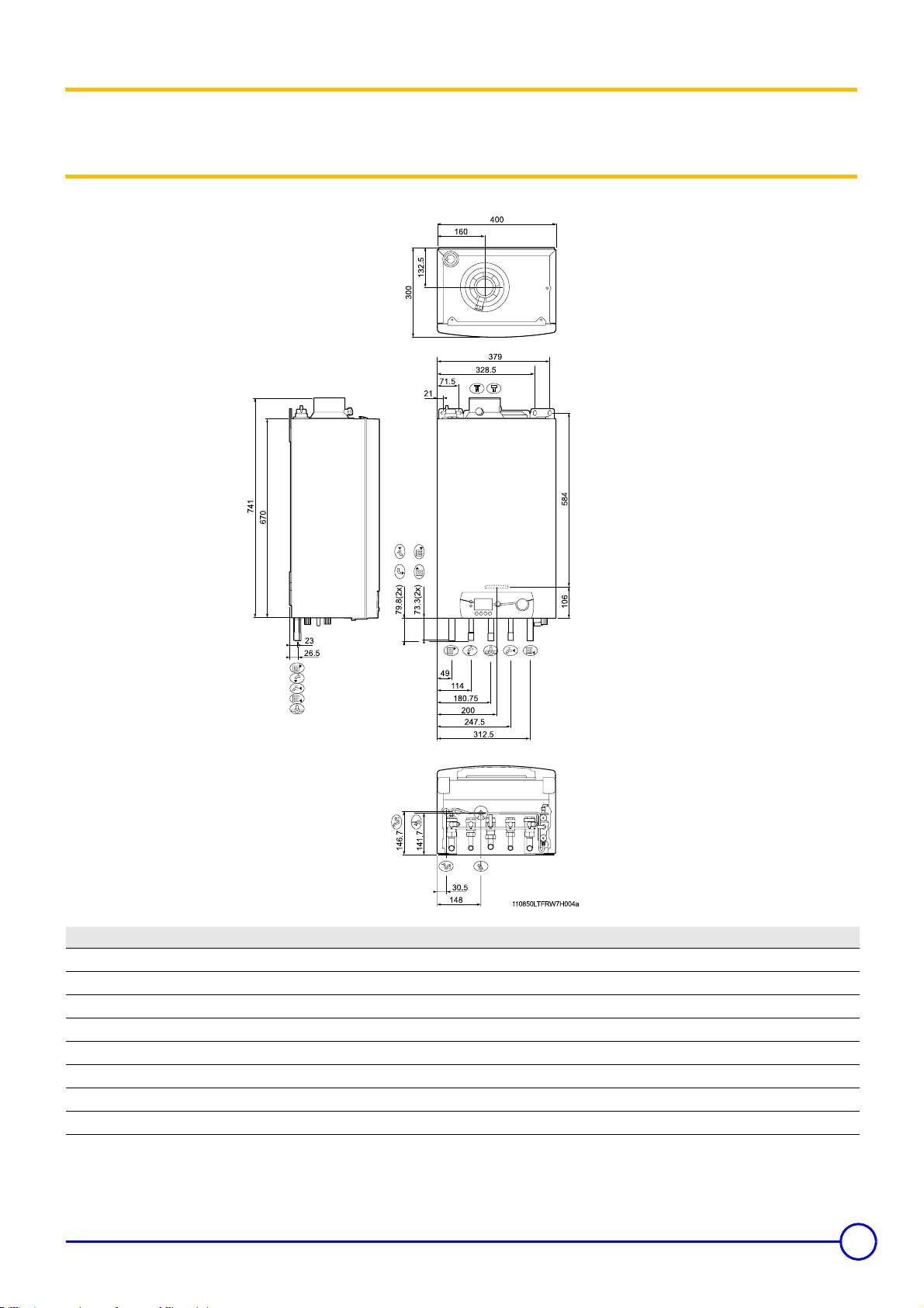
Main dimensions . . . . . . . . . . . . . . . . . . . . . . . . . . . . . . . . . . . . . . . . . . . . . . . . . . . . . . . . . . . . . . . . . . . . . . . . . . . . .8
1 Package list (Standard delivery). . . . . . . . . . . . . . . . . . . . . . . . . . . . . . . . . . . . . . . . . . . . . . . . . . . . . . . . . . . . . . . . . . . . . . . . . . . . . . .8
2 Serial number. . . . . . . . . . . . . . . . . . . . . . . . . . . . . . . . . . . . . . . . . . . . . . . . . . . . . . . . . . . . . . . . . . . . . . . . . . . . . . . . . . . . . . . . . . . . .8
3 Mounting frame . . . . . . . . . . . . . . . . . . . . . . . . . . . . . . . . . . . . . . . . . . . . . . . . . . . . . . . . . . . . . . . . . . . . . . . . . . . . . . . . . . . . . . . . . . .9
4 Boiler installed . . . . . . . . . . . . . . . . . . . . . . . . . . . . . . . . . . . . . . . . . . . . . . . . . . . . . . . . . . . . . . . . . . . . . . . . . . . . . . . . . . . . . . . . . . . .9
Operation . . . . . . . . . . . . . . . . . . . . . . . . . . . . . . . . . . . . . . . . . . . . . . . . . . . . . . . . . . . . . . . . . . . . . . . . . . . . . . . . . .11
1 Control panel . . . . . . . . . . . . . . . . . . . . . . . . . . . . . . . . . . . . . . . . . . . . . . . . . . . . . . . . . . . . . . . . . . . . . . . . . . . . . . . . . . . . . . . . . . . .12
2 Parameter display . . . . . . . . . . . . . . . . . . . . . . . . . . . . . . . . . . . . . . . . . . . . . . . . . . . . . . . . . . . . . . . . . . . . . . . . . . . . . . . . . . . . . . . .13
Hydraulic specifications . . . . . . . . . . . . . . . . . . . . . . . . . . . . . . . . . . . . . . . . . . . . . . . . . . . . . . . . . . . . . . . . . . . . . .16
1 Boiler pump . . . . . . . . . . . . . . . . . . . . . . . . . . . . . . . . . . . . . . . . . . . . . . . . . . . . . . . . . . . . . . . . . . . . . . . . . . . . . . . . . . . . . . . . . . . . .16
2 Expansion chamber . . . . . . . . . . . . . . . . . . . . . . . . . . . . . . . . . . . . . . . . . . . . . . . . . . . . . . . . . . . . . . . . . . . . . . . . . . . . . . . . . . . . . . .16
Installation . . . . . . . . . . . . . . . . . . . . . . . . . . . . . . . . . . . . . . . . . . . . . . . . . . . . . . . . . . . . . . . . . . . . . . . . . . . . . . . . .17
1 Water treatment and connections . . . . . . . . . . . . . . . . . . . . . . . . . . . . . . . . . . . . . . . . . . . . . . . . . . . . . . . . . . . . . . . . . . . . . . . . . . . .19
2 Connecting the options. . . . . . . . . . . . . . . . . . . . . . . . . . . . . . . . . . . . . . . . . . . . . . . . . . . . . . . . . . . . . . . . . . . . . . . . . . . . . . . . . . . . .27
3 Connecting the external controls . . . . . . . . . . . . . . . . . . . . . . . . . . . . . . . . . . . . . . . . . . . . . . . . . . . . . . . . . . . . . . . . . . . . . . . . . . . . .28
4 Connection of the domestic hot water sensor . . . . . . . . . . . . . . . . . . . . . . . . . . . . . . . . . . . . . . . . . . . . . . . . . . . . . . . . . . . . . . . . . . .31
5 Antifreeze protection . . . . . . . . . . . . . . . . . . . . . . . . . . . . . . . . . . . . . . . . . . . . . . . . . . . . . . . . . . . . . . . . . . . . . . . . . . . . . . . . . . . . . .31
6 Safety contact. . . . . . . . . . . . . . . . . . . . . . . . . . . . . . . . . . . . . . . . . . . . . . . . . . . . . . . . . . . . . . . . . . . . . . . . . . . . . . . . . . . . . . . . . . . .32
7 Connection of a remote alarm transfer and boiler operation indication system (Not proposed) . . . . . . . . . . . . . . . . . . . . . . . . . . . . .32
8 Pump logic . . . . . . . . . . . . . . . . . . . . . . . . . . . . . . . . . . . . . . . . . . . . . . . . . . . . . . . . . . . . . . . . . . . . . . . . . . . . . . . . . . . . . . . . . . . . . .33
Commissionning . . . . . . . . . . . . . . . . . . . . . . . . . . . . . . . . . . . . . . . . . . . . . . . . . . . . . . . . . . . . . . . . . . . . . . . . . . . .34
1 Commissionning. . . . . . . . . . . . . . . . . . . . . . . . . . . . . . . . . . . . . . . . . . . . . . . . . . . . . . . . . . . . . . . . . . . . . . . . . . . . . . . . . . . . . . . . . .34
2 Commissioning. . . . . . . . . . . . . . . . . . . . . . . . . . . . . . . . . . . . . . . . . . . . . . . . . . . . . . . . . . . . . . . . . . . . . . . . . . . . . . . . . . . . . . . . . . .39
Adapting to another gas . . . . . . . . . . . . . . . . . . . . . . . . . . . . . . . . . . . . . . . . . . . . . . . . . . . . . . . . . . . . . . . . . . . . . .44
1 Switching from Natural Gas to Propane. . . . . . . . . . . . . . . . . . . . . . . . . . . . . . . . . . . . . . . . . . . . . . . . . . . . . . . . . . . . . . . . . . . . . . . .44
2 Setting the control unit parameters . . . . . . . . . . . . . . . . . . . . . . . . . . . . . . . . . . . . . . . . . . . . . . . . . . . . . . . . . . . . . . . . . . . . . . . . . . .44
Maintenance . . . . . . . . . . . . . . . . . . . . . . . . . . . . . . . . . . . . . . . . . . . . . . . . . . . . . . . . . . . . . . . . . . . . . . . . . . . . . . . .46
1 Inspection. . . . . . . . . . . . . . . . . . . . . . . . . . . . . . . . . . . . . . . . . . . . . . . . . . . . . . . . . . . . . . . . . . . . . . . . . . . . . . . . . . . . . . . . . . . . . . .46
2 Maintenance. . . . . . . . . . . . . . . . . . . . . . . . . . . . . . . . . . . . . . . . . . . . . . . . . . . . . . . . . . . . . . . . . . . . . . . . . . . . . . . . . . . . . . . . . . . . .49
Electrical diagram . . . . . . . . . . . . . . . . . . . . . . . . . . . . . . . . . . . . . . . . . . . . . . . . . . . . . . . . . . . . . . . . . . . . . . . . . . .53
Breakdown codes . . . . . . . . . . . . . . . . . . . . . . . . . . . . . . . . . . . . . . . . . . . . . . . . . . . . . . . . . . . . . . . . . . . . . . . . . . .54
Spare parts - MCR 24, 24/28 MI, 30/35 MI, 34/39 MI. . . . . . . . . . . . . . . . . . . . . . . . . . . . . . . . . . . . . . . . . . . . . . . . .60
MCR 24, 24/28 MI, 30/35 MI, 34/39 MI 08/06/06-300008460-001-B
Page 3

Declaration of compliance
1
Declaration of compliance A.R. 8/1/2004 - BE
Manufacturer DE DIETRICH THERMIQUE S.A.S.
57 rue de la Gare
F - 67580 MERTZWILLER
+33 3 88 80 27 00
*
+33 3 88 80 27 99
+
Issued by See end of notice
We hereby certify that the series of appliances specified hereinafter is in compliance with the standard model described in the EC declaration
of compliance, and that it is manufactured and marketed in compliance with the requirements and standards of the following European
Directives:
Product type Wall-hung gas boilers
Formats MCR 24
MCR 24/28 MI
MCR 30/35 MI
MCR 34/39 MI
Standard applied - 90/396/EEC Gas Appliance Directive
Reference Standards : EN 437; EN 483; EN 625; EN 677
- 73/23/EEC Low Voltage Directive
Reference Standards : EN 60.335.1
- 89/336/EEC Electromagnetic Compatibility Directive
Generic standards : EN1000-6-3 ; EN 61000-6-1
- 92/42/EEC Efficiency Directive ****
Inspecting organisation Gastec (Netherland)
Values: Standards EN 297 A3 NOx < 114 (mg/kWh) 65 ppm; CO < 65 (mg/kWh) 65 ppm
Date 22/06/04
Signature Technical Director
Mr Bertrand SCHAFF
1
08/06/06 - 300008460-001-B MCR 24, 24/28 MI, 30/35 MI, 34/39 MI
3
Page 4

Symbols used
Caution danger
Risk of injury and damage to equipment. Attention must be
paid to the warnings on safety of persons and equipment
Important information
Information must be kept in mind to maintain comfort
Important recommendations
MCR boilers must be installed :
- in a frost-free room;
- as close as possible to draw-off points in order to minimise energy
losses through the pipes.
Installation must be carried out in accordance with the prevailing
regulations, the codes of practice and the recommendations in these
instructions.
Keep this document close to the place where the tank is
installed.
The first start-up is to be performed by your installation engineer.
Only original spare parts must be used.
Any intervention on the appliance and heating equipment must be
carried out by a qualified technician. Please confirm to the user of the
installation that you have carried out a leak tightness check on the
gas circuit.
For the application of article 25 of the modified decree dated 02/08/
1977 and of article 1 of the modifed decree dated 05/02/1999, the
installation engineer must be in possession of the certificates of
compliance approved by the Ministries in charge of construction and
gas safety.
Any work on the gas valve unit is authorised only if carried out
by a qualified professional.
Reference
Z
Refer to another manual or other pages in this instruction
manual
DHW:Domestic hot water
The manufacturer is not liable for any improper use of the
appliance or failure to maintain or install the unit correctly
(the user shall take care to ensure that the system is
installed by a qualified fitter).
Work on electrical equipment must be carried out by a qualified
professional in compliance with the prevailing legislation.
We shall not accept any responsibility for any damage and
disturbance arising from not following these instructions.
Service the appliance regularly to ensure that it operates
correctly.
Belgium
The installation and maintenance of the boiler must be done by a
qualified professional in compliance with the prevailing local and
national regulations.
The boiler is preset in the factory to operate on natural gas.
It is formally prohibited to interfere with the gas block.
Other countries
The installation and maintenance of the boiler must be done by a
qualified professional in compliance with the prevailing local and
national regulations.
For Belgium: The operations required to switch from one gas
to another must be carried out by a SERV'elite technician.
Prior to commissioning, compare the factory settings of the appliance
with the local power supply conditions. If the settings have to be
modified, this must be carried out by a qualified professional.
Condensation boilers require a flue gas evacuation system or a fresh
air inlet specially adapted to the method of operation. Its execution
depends on the place of installation and the building.
Compliance with a minimum distance between the flue gas
evacuation system in forced flue mode or the boiler with combustible
substances is not necessary (For Belgium: Comply with the NBN
B61-002 standard). At nominal output, the temperature of the
components does not exceed 85 °C.
4
MCR 24, 24/28 MI, 30/35 MI, 34/39 MI 08/06/06-300008460-001-B
Page 5
Description
MCR boilers are gas condensing boilers; they handle :
- central heating using radiators or underfloor heating
(MCR 24);
- central heating and instant domestic hot water production
(MCR ... MI).
The boilers operate on natural gas or propane. They are factory set
for natural gas H.
If converting to propane :
See "Adapting to another gas"
Z
The MCR 24 boiler can be connected to a 80 or 130 litre tank to
produce domestic hot water.
For Belgium: Any intervention on the gas valve unit is
strictly forbidden.
For use with natural gas L or propane, it is necessary to adjust the
boiler.
Boilers MCR 24 MCR 24/28 MI MCR 30/35 MI MCR 34/39 MI*
No. CE PIN 0063BQ3009
B
Type
Flue gas evacuation Forced flue
Ignition Automatic
Gas Natural gas / Propane
23P
, B33, C
13(x)
, C
33(x)
, C
43(x)
, C53, C
63(x)**
, C
83(x)
* Italy: Not proposed ** Except Belgium
1 Package list
- Boiler package with mounting frame. Can be used to make the
water, gas and water evacuation connections: Safety valve,
- Accessories package, dependent on the type and length of the
forced flue
disconnector, condensates run-off.
2 Certifications
User country FR ES, GB, GR, IE, IT, PT BE PL
Category
Gas
Supply pressure
User country CZ HU RO, SI
Category
Gas
Supply pressure
II
2Esi3P
GN H Propane GN H Propane G20/25 E (G20) Ls
GN L G31 Lw G31
20 mbar 37 mbar 20 mbar 29 mbar 20/25 mbar 20 mbar 13 mbar
25 mbar 37 mbar 20 mbar 36 mbar
II
2H3P
GN H Propane GN H Propane G20
20 mbar 50/29 mbar 25 mbar 28-30/50 mbar 20 mbar
30/37/50 mbar 30 mbar
II
2H3P
II
2H3P
I
2E(S)B
, I
3P
II
2ELwLs3P
II
G31
2H3P
08/06/06 - 300008460-001-B MCR 24, 24/28 MI, 30/35 MI, 34/39 MI
5
Page 6
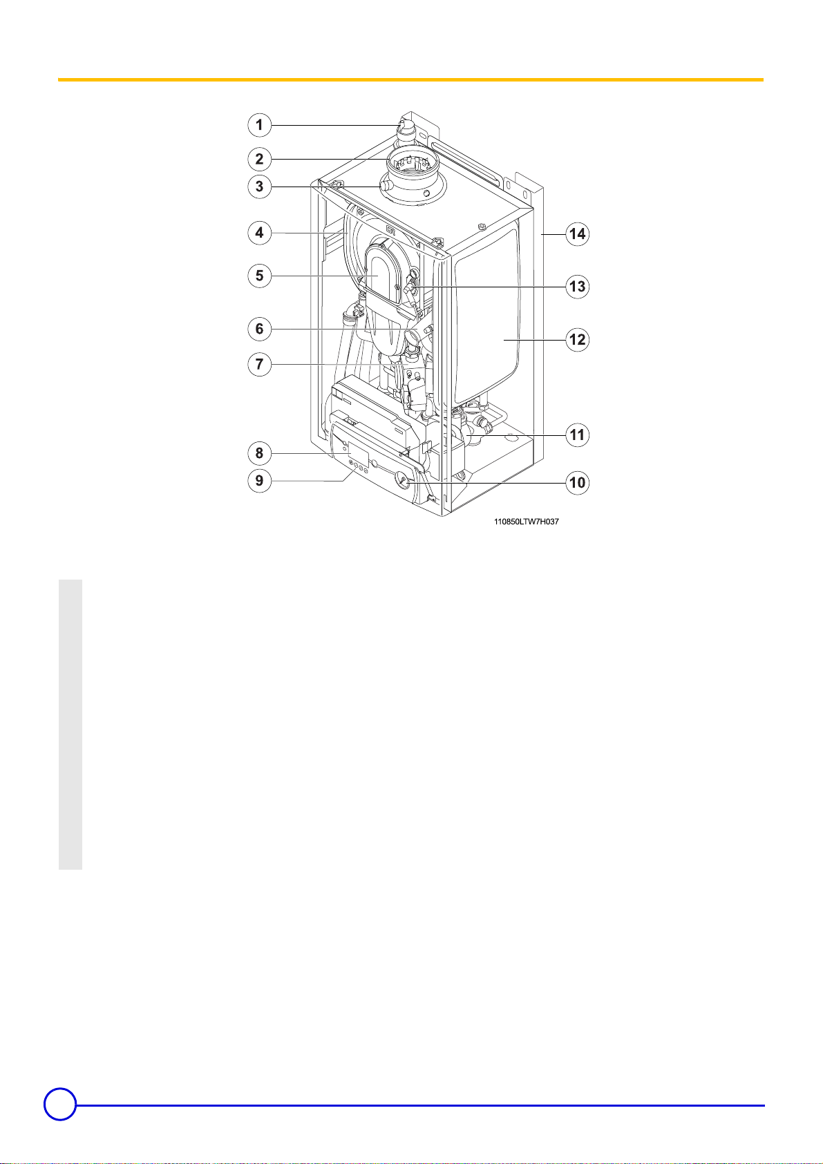
3Main parts
Automatic bleed valve
1.
Smoke nozzle
2.
Outlet for measuring combustion hygiene
3.
Heat exchanger
4.
Air/gaz canal
5.
Fan air inlet
6.
Gas block
7.
Display
8.
Control panel
9.
Pressure gauge
10.
Circulating pump
11.
Expansion chamber (only for MCR 24,MCR24/28 MI,MCR 30/35 MI)
12.
Ignition/ionisation electrode
13.
Stand off mounting frame (optional)
14.
Expansion chamber (optional): only for MCR 34/39 MI
6
MCR 24, 24/28 MI, 30/35 MI, 34/39 MI 08/06/06-300008460-001-B
Page 7

4 Technical data
Boilers MCR 24 MCR 24/28MI MCR 30/35MI MCR 34/39MI
Nominal useful output 40/30 (Heating mode) (min./max) kW 6.3/25 6.3/25 6.6/31.3 6.8/35.5
Nominal useful output 80/60 (min./max) kW 5.5/23.6 5.5/23.6 5.7/29.5 5.9/33.3
Nominal useful output (DHW mode) (min./ max) kW - 27.4 34.3 38.2
Nominal input power (heatin g an d DH W modes) kW 24/24 24/28 30/35 34/39
Minimum useful output 40/30 (Heating mode) kW 6.3 6.3 6.6 6.8
Minimum input power (heating and DHW modes) kW 5.8 5.8 6.1 6.3
Gas flow rate à Pn (à 15°C - 1013 mbar):
Natural gas H
Natural gas L
Propane
PCI efficiency, Load and water temperature efficiency:
100% Nominal power, Average temperature: 70°C
100% Nominal power, Return temperature: 30°C
30% Nominal power, Return temperature: 30°C
Maximum temperature (Safety thermostat cut-off) °C 110 110 110 110
Losses when off (∆T = 30 °C) W30302928
Losses through the outer casing % 1.1 1.1 0.9 0.5
Water capacity l 1.7 1.8 2 2.2
Weight without water, without mounting frame, without cladding kg 29 30.5 32 31.5
kW
3
m
3
m
Kg/h
%
%
%
/h
/h
24
2.4
2.8
1.9
98.3
104.4
108.7
Specifications of the heating circuit
Nominal water flow (∆T = 20 K) l/h 1.03 1.03 1.29 1.47
Rated net head (∆T = 20 K) mbar >200 >200 >200 >200
Flow temperature °C 75 75 75 75
Maximum pressure bar3333
Expansion chamber l8 8 8 -
Initial pressure of the expansion tank bar1111
Minimum operating pressure bar 0.8 0.8 0.8 0.8
Domestic hot water specifications
Instruction set outlet temperature °C 55 55 55 55
Specific hot water flow (∆T = 30 K) l/min - 14 16 19
Nominal max cold water pressure bar8888
Minimum pressure (11 l/min) bar - 1.4 0.4 0.4
Combustion products circuit
Connecting
Mass flue gas flow rate (min./max) Kg/h 10/40 10/47 10/59 10/62
Flue gas temperature 80/60 °C 78 78 74 71.5
Pressure available at the flue gas nozzle Pa 50 100 100 140
Condensation water pH 50/30 - 1-7 1-7 1-7 1-7
diameter
(mm)
60/100 60/100 60/100 60/100
Electrical specifications
Power supply voltage (50 Hz) V 230 230 230 230
Power consumption W 115 115 150 180
Electrical output circulating pump W 90 90 125 135
Auxiliary electrical output (Nominal power, ex circulating pump) W25252545
Insulation class IPX4D IPX4D IPX4D IPX4D
24
2.4
2.8
1.9
98.3
104.4
108.7
35
3.5
4.1
2.7
98.2
104.4
109.7
39
3.9
4.5
3.0
98
104.4
110.5
1 mbar = 100 Pa - 1 daPa ~ 1 mm H
O
2
Cold water temperature: 10 °C; Domestic hot water temperature:
85 °C
08/06/06 - 300008460-001-B MCR 24, 24/28 MI, 30/35 MI, 34/39 MI
7
Page 8
Main dimensions
1 Package list (Standard delivery)
• France + Other countries
Boiler package Forced flue package
Boilers
MCR 24 HG1 DY847 CX50
MCR 24/28MI HG2 DY847 CX50
MCR 30/35MI HG3 DY847 CX50
MCR 34/39MI HG4 DY847 CX50
• Belgium
Boiler package Forced flue package
Boilers
MCR 24 BE HG5 DY847 CX50
MCR 24/28MI BE HG6 DY847 CX50
MCR 30/35MI BE HG7 DY847 CX50
MCR 34/39MI BE HG8 DY847 CX50
Horizontal
(diameter 60/100)
Horizontal
(diameter 60/100)
Vertical
(diameter 80/125)
Vertical
(diameter 80/125)
2 Serial number
The serial number can be found on the boiler's rating plate.
C000655
8
MCR 24, 24/28 MI, 30/35 MI, 34/39 MI 08/06/06-300008460-001-B
Page 9
3 Mounting frame
A stand off frame is an option for easy and fast upward piping behind the boiler; a pipework kit is an option for a upward piping in
combination with the stand off frame.
4 Boiler installed
MCR 24
France + Other countries Belgium + Germany + Poland
Return connection (Inside diameter 18 mm) Return connection (External diameter 22 mm)
Flow connection (Inside diameter 18 mm) Flow connection (External diameter 22 mm)
Gas connection (Inside diameter 18 mm) Gas connection (External diameter 22 mm)
Combustion air inlet (diameter 100) Combustion air inlet (diameter 100)
Flue gas discharge duct (diameter 60) Flue gas discharge duct (diameter 60)
Return storage tank (Inside diameter 16 mm) Return storage tank (External diameter 15 mm)
¢ Outlet storage tank (Inside diameter 16 mm) ¢ Outlet storage tank (External diameter 15 mm)
Condensates evacuation pipe (3/4") Condensates evacuation pipe (3/4")
º Safety valve (diameter 15) º Safety valve (diameter 15)
08/06/06 - 300008460-001-B MCR 24, 24/28 MI, 30/35 MI, 34/39 MI
9
Page 10

MCR 24/28MI, 30/35MI, 34/39MI
France + Other countries Belgium + Germany + Poland
Return connection (Inside diameter 18 mm) Return connection (External diameter 22 mm)
Flow connection (Inside diameter 18 mm) Flow connection (External diameter 22 mm)
Gas connection (Inside diameter 18 mm) Gas connection (External diameter 22 mm)
Combustion air inlet (Ø 100 mm) Combustion air inlet (Ø 100 mm)
Flue gas discharge duct (Ø 60 mm) Flue gas discharge duct (Ø 60 mm)
Return storage tank (Inside diameter 16 mm) Return storage tank (External diameter 15 mm)
¢ Outlet storage tank (Inside diameter 16 mm) ¢ Outlet storage tank (External diameter 15 mm)
Condensates evacuation pipe (3/4") Condensates evacuation pipe (3/4")
º Safety valve (Ø 15 mm) º Safety valve (Ø 15 mm)
10
MCR 24, 24/28 MI, 30/35 MI, 34/39 MI 08/06/06-300008460-001-B
Page 11

MCR boilers are equipped with a control panel with electronic
regulation including security and flame surveillance by ionisation
probe.
The boiler is not sensitive to phase reversal. The normal maximum
absorbed power is between 115 W and 130 W. The boiler is entirely
pre-wired. All external connections can be made with terminal block
X9.
Boiler MCR power can be regulated in several ways:
Dry contact room thermostat (Commutation without power): The
boilers internal control will modulate the output to achieve the flow
temperature set point of the boiler. The contact is on the X9 terminal
strip (low voltage only).
All connections on terminal block X1,X2,X4,X5,X6,X7 are in
230 V.
All connections on terminal block X9 are low voltage only.
The MCR is a modular boiler whose temperature can be regulated
using one of the following solutions:
- Regulation as a function of room temperature:
- Easymatic,Easyradio communicating room regulation + Interface
PCB (AD 221)
- Regulation: Outside sensor alone
- Regulation as a function of the outside temperature + Outside
sensor alone:
- Easymatic,Easyradio + Outside sensor + Interface PCB (AD 221)
- Regulation as a function of the outside temperature with a 3channel valve circuit:
- Easymatic or Easyradio + Outside sensor + Interface PCB (AD
222)
Operation
The MCR boiler is fitted with an electronic temperature regulator with
outlet and return temperature sensors. The outlet temperature can be
set between 20 and 85. The boiler increases or lowers power as a
function of instructions.
08/06/06 - 300008460-001-B MCR 24, 24/28 MI, 30/35 MI, 34/39 MI
11
Page 12
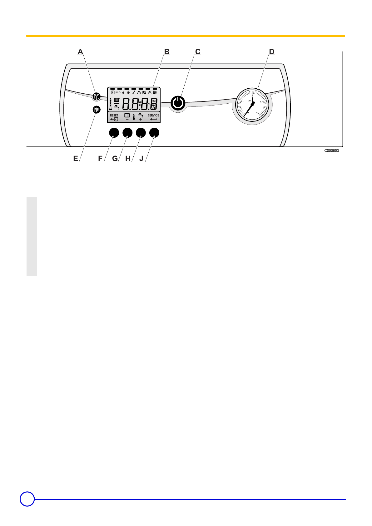
1 Control panel
The control panel of the MCR boiler has 6 function keys, an on/off
switch and a screen. The function keys are used to read or modify
parameters and temperatures.
A Menu key
BDisplay
C Main ON/OFF switch
D Pressure gauge
E Sweep key
F "Escape" or "Reset" key
G Heating temperature adjustment key or -
H DHW temperature adjustment key or +
J Maintenance key or enter
The display includes 4 positions and several symbols which indicate
the operating status of the control panel and any disturbances.
Figures, points and/or letters may be displayed.
The symbols located above the function keys indicate their current
function.
Pressing on any key will display the current status of the boiler and
the current command code. If there is a malfunction, the
corresponding code continues to be displayed.
12
MCR 24, 24/28 MI, 30/35 MI, 34/39 MI 08/06/06-300008460-001-B
Page 13
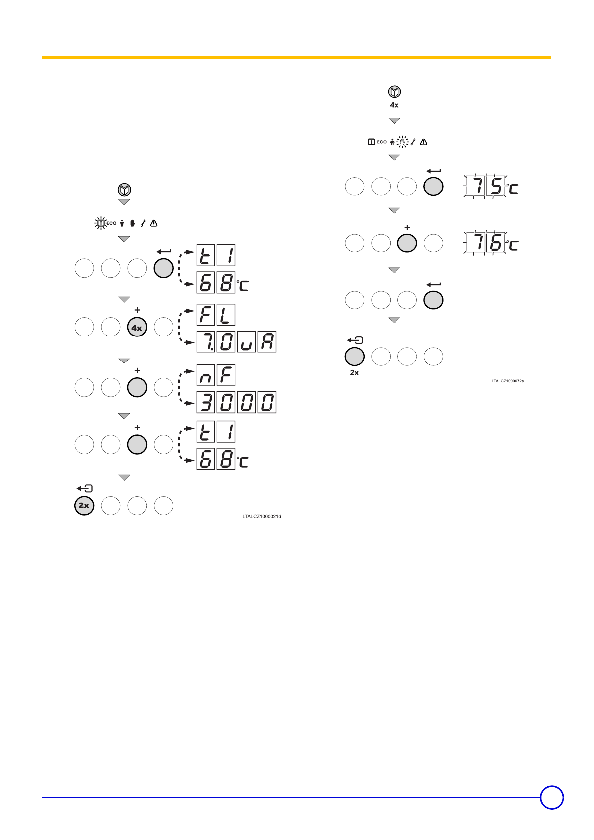
2 Parameter display
The following parameters can be displayed in the information menu
:
- t1 = Flow temperature (°C)
- t2 = Return temperature (°C)
- t3 = Tank sensor (°C)
- t4 = Outside temperature (°C)
- FL = Ionisation current (µA)
- nF = Fan speed (rpm)
2.1 Setting the manual mode ()
- Press the Ä key. The symbol flashes. To access the
parameters, press key l.
- Press the + key successively to scroll down the various
parameters.
- Press key Ä several times until the symbol flashes on the
menu bar.
- Press the l key. The minimum outlet temperature P1 or the text
Auto is displayed if an outside temperature sensor is installed.
- Press the + key to increase the outlet temperture manually.
- To confirm, press the l key.
The installation is in manual mode.
- Press key 1 time to deactivate the manual mode.
- Press key 1 time to return to the current operating mode.
08/06/06 - 300008460-001-B MCR 24, 24/28 MI, 30/35 MI, 34/39 MI
13
Page 14
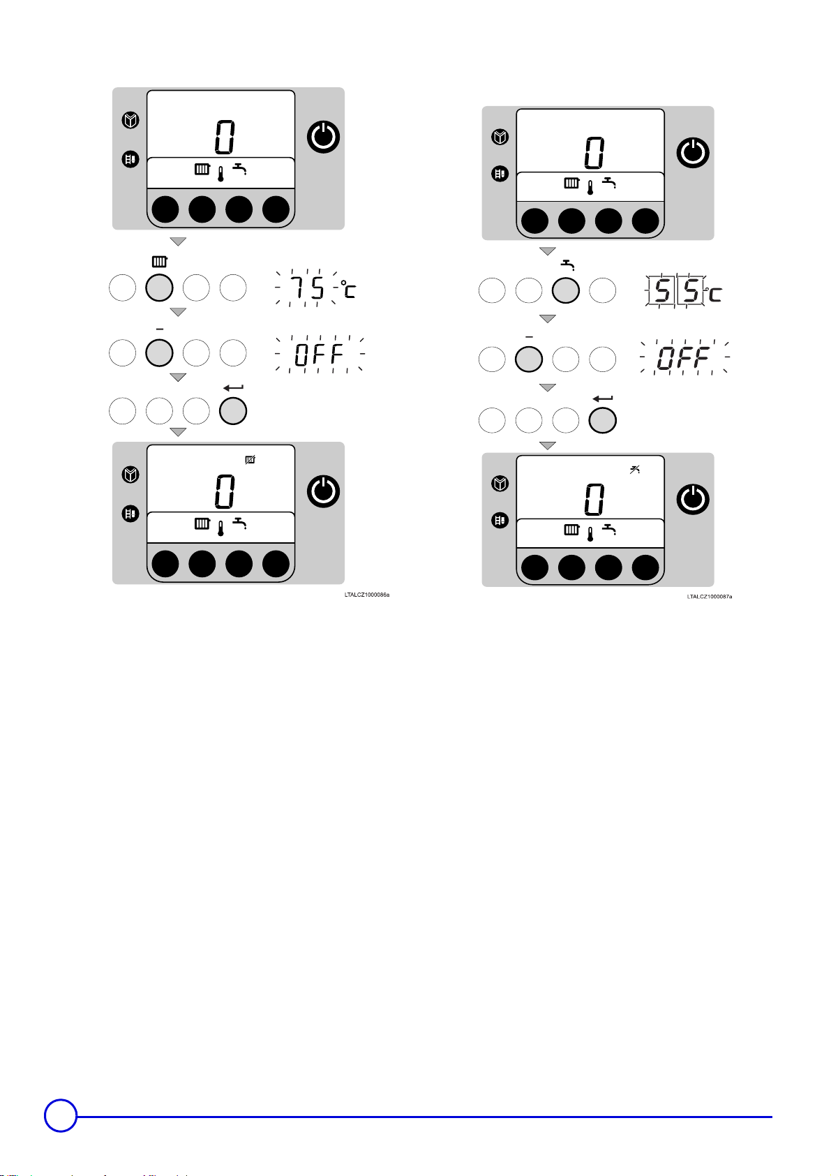
2.2 Switching off the central heating (In summer mode)
2.3 Switching off the domestic hot water()
- Starting from the current operating status, press key .
- The symbol and the current temperature are displayed.
- Press the - key until the OFF symbol is displayed.
- Press the l key to modify the setting.
- The symbol appears.
production of domestic hot water: activated.
- Starting from the current operating status, press key .
- The symbol and the current temperature are displayed.
- Press the - key until the OFF symbol is displayed.
- Press the l key to modify the setting.
- The symbol appears.
14
MCR 24, 24/28 MI, 30/35 MI, 34/39 MI 08/06/06-300008460-001-B
Page 15
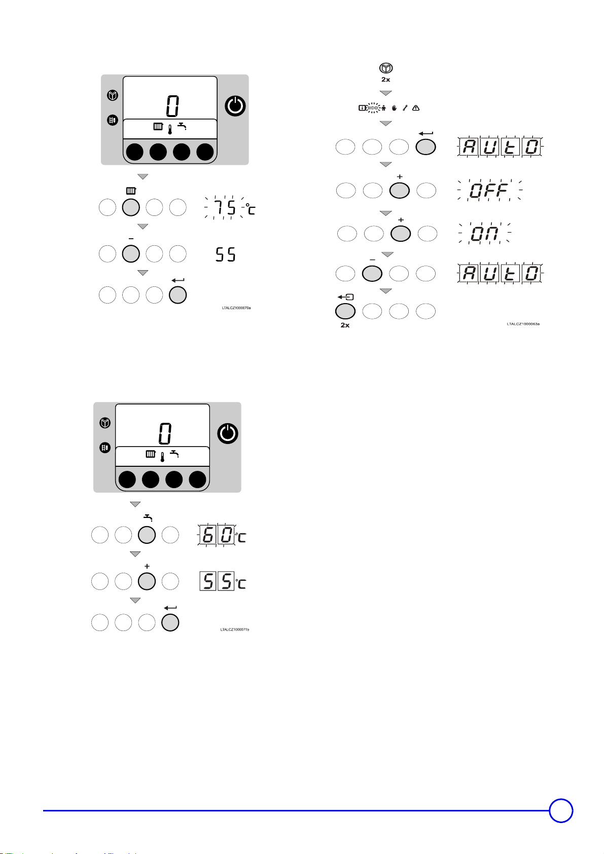
2.4 Modifying the water outlet temperature in the heating
installation
- Starting from the current operating status, press key .
- The symbol and the current temperature are displayed.
- Press the + or - key to modify the value.
- To confirm, press the l key.
2.5 Setting the domestic hot water temperature
2.6 Modifying the comfort setting (ECO)
The user can consult or modify the following 3 settings:
- ON = Activation of the energy-saving setting.
- OFF = Activation of the comfort setting
- AUTO = Setting dependent on the control unit (=Factory setting).
- Press the Ä key. The symbol flashes.
- Press the Ä key a second time. The symbol ECO flashes.
- To confirm, press the l key.
- The current operating status is shown on the display: ECO.
- Press the key to return to the ECO menu or press the + key
to modify the status.
- To confirm, press the l key.
- Press key 1 time to return to the current operating mode.
In ECO mode: I
If the ECO mode is set to I, when the boiler is used with an
external hot water tank, the water is not heated. If the hot water
tank is empty, the tap water will therefore be cold.
In Auto mode
If the setting is on Auto and the control unit is fitted with a ECO
function, the appliance adapts to the control unit setting.
For example: The ECO setting is tripped at night during reduced
temperature operation.
- Starting from the current operating status, press key .
- The symbol and the current temperature are displayed.
- Press the + or - key to modify the value.
- To confirm, press the l key.
08/06/06 - 300008460-001-B MCR 24, 24/28 MI, 30/35 MI, 34/39 MI
15
Page 16
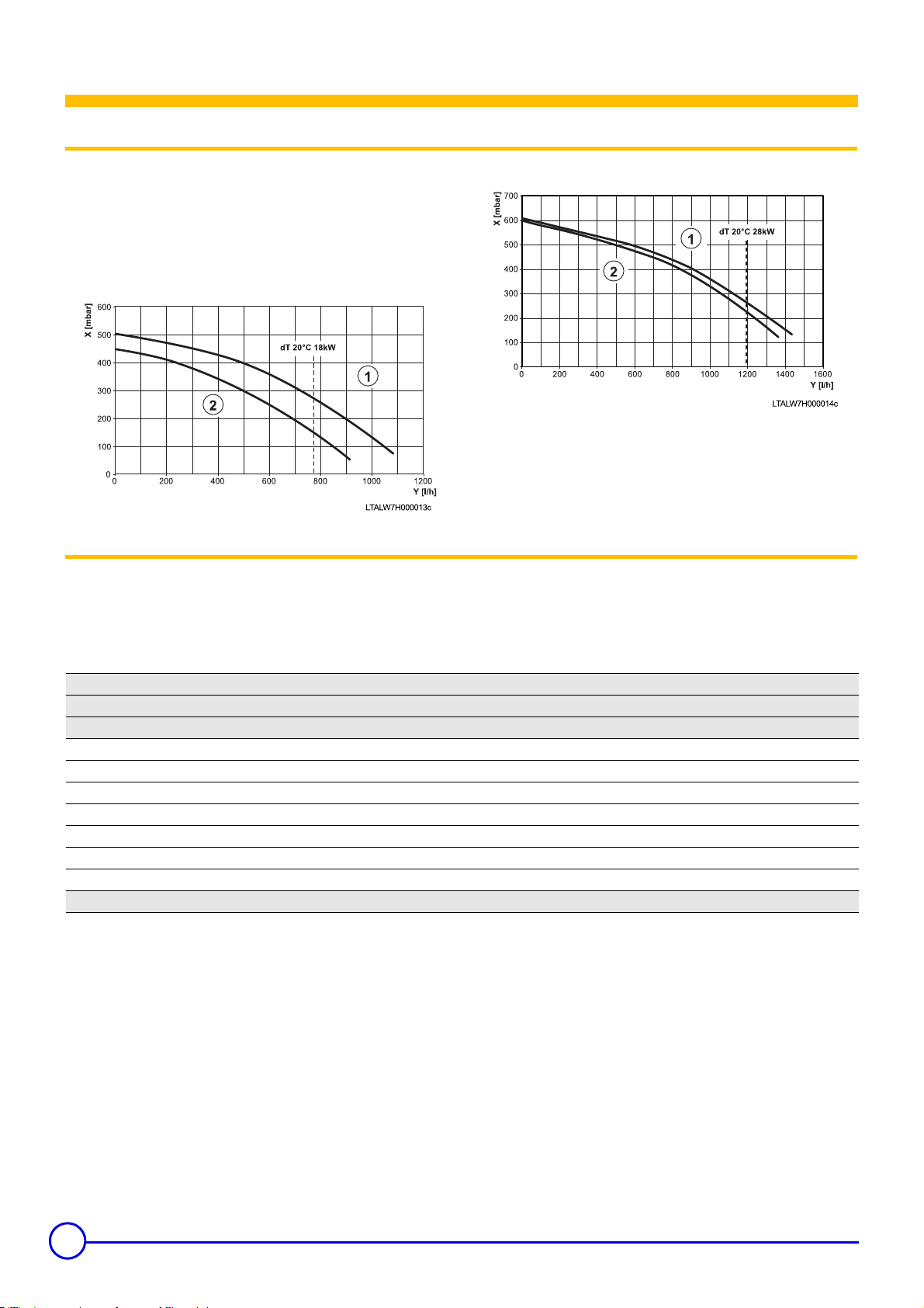
1 Boiler pump
Hydraulic specifications
Depending on the flow, the following diagrams represent::
manometric heights available at boiler outlet.
For a fixed flow, the manometric height available at the boiler outlet
is obtained by taking the difference between the manometric height
of the circulator pump and the loss of load in the boiler.
• MCR 24, MCR 24/28 MI
2 Expansion chamber
The boiler is fitted as standard with an 8-litre expansion tank (except
MCR34/39 MI) (Initial pressure of the expansion tank 1 bar). The total
water volume is determined according to the static height of the
installation and for an average water temperature of 80°C (Outlet :
80; Return : 60).
• MCR 34/39 MI
X: Rated net head
Y: Flow rate
: High manometric pump
: Low pressure pump
Pressure: Safety valve 3
Initial pressure of the expansion tank (bar) 0.5 1 1.5
Total water volume (litres) Volume of the expansion vessel (litres)
100 4.8 8 13.3
125 6 10 16.6
150 7.2 12 20
175 8.4 14 23.3
200 9.6 16 26.6
250 12 20 33.3
300 14.4 24 39.9
To obtain other volumes, multiply the volume of the system by one of the factors: 0.048 0.080 0.133
If the water volume is greater than 100 litres or the static height of the
system exceeds 5 metres, an additional expansion tank must be
fitted.
16
MCR 24, 24/28 MI, 30/35 MI, 34/39 MI 08/06/06-300008460-001-B
Page 17

Installation
Residential buildings for France
Statutory terms and conditions of installation and maintenance
The installation and maintenance of the appliance must be carried
out by a qualified professional in compliance with the statutory texts
of the codes of conduct in force, particularly :
- Order of 2 August 1977
Technical and safety rules applicable to combustible gas and
liquefied hydrocarbon installations situated inside residential
buildings and their annexes.
- NF P 45-204 standards
Gas installation, (formerly DTU 61-1, gas installations: April 1982,
addendum no 1: July 1984).
- Local Sanitary Regulations
For appliances connected to the electricity network:
- NF C 15-100 standards Low voltage electrical installation - Rules.
Establishments open to the public (France)
Statutory terms and conditions of installation
The installation and maintenance of the appliance must be carried
out in compliance with the statutory texts and rules of the codes of
conduct in force, particularly:
- Safety regulations against fire and panic in establishments open to
the public:
a. General regulations
For all appliances:
- Articles GZ - Installations operating on combustible gases and
liquefied hydrocarbons
Then, depending on use:
- Articles CH-Heating, ventilation, refrigeration, air conditioning and
production of steam and domestic hot water
b. Instructions specific to each type of establishment open to
the public (hospitals, stores, etc.)
Belgium
The boiler installation and gas connection must be carried out by a
qualified professional in compliance with the NBN D 51.003, NBN D
30.003, NBN B 61.001, NBN B 61.002 and NBN D 51.006 standards.
An ARGB approved stop valve must be fitted in the pipe leading to
and close to the boiler.
Electrical connections must comply with the instructions in the
general regulations on electrical installations (RGIE).
Belgium:the cross-section of the aeration vents, which are
compulsory in the room in which the boiler is installed, must comply
with the NBN D 51-003 standard.
08/06/06 - 300008460-001-B MCR 24, 24/28 MI, 30/35 MI, 34/39 MI
17
Page 18
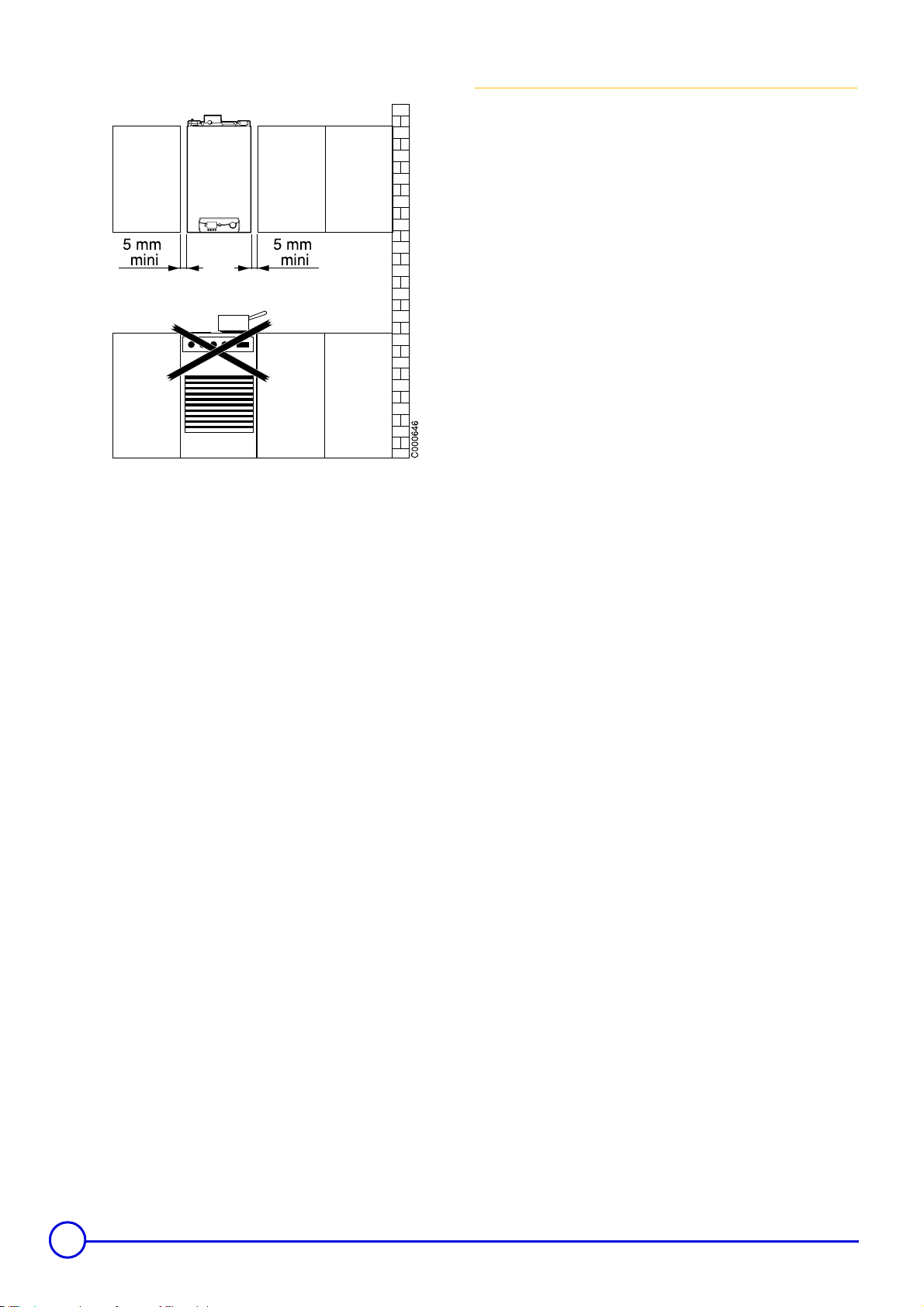
The boiler must not be positioned above a heat source or a
cooking appliance
- The boiler must be fixed to a solid surface, capable of bearing the
weight of the appliance and other equipment when full of water.
- To enable removal and replacement of the cladding, a space of 5
mm is sufficient on either side of the boiler.
- The IPX4D protection index authorises installation in bathrooms,
except for protection volumes 1 and 2 however.
Certificate of compliance
For the application of article 25 of the modified decree dated 02/08/
1977 and of article 1 of the modifed decree dated 05/02/1999, the
installation engineer must be in possession of the certificates of
compliance approved by the Ministries in charge of construction and
gas safety:
- Different forms (forms 1, 2 or 3) for a new gas installation,
- "Model 4" in particular after replacing a furnace with a new one.
In order to avoid damage to the boilers, it is necessary to
prevent the contamination of combustion air by chlorine
and/or fluoride compounds, which are particularly
corrosive. These compounds are present, for example, in
aerosol sprays, paints, solvents, cleaning products,
washing products, detergents, glues, snow clearing salts,
etc.
Therefore:
- Do not suck in air evacuated from premises using such
products: hairdressing salons, dry cleaners, industrial
premises (solvents), premises containing refrigeration
systems (risk of refrigerant leakage), etc.
- Do not stock such products close to the boilers.
If the boiler and/or peripheral equipment are corroded by
such chloride or fluoride compounds, the contractual
guarantee cannot be applied.
Comply with current regulations.
If using thermostatic valves, it is not necessary to fit them to every
radiator.
Never fit radiators in the room in which the room
temperature thermostat is installed with thermostatic
valves.
18
MCR 24, 24/28 MI, 30/35 MI, 34/39 MI 08/06/06-300008460-001-B
Page 19
1 Water treatment and connections
Fill the heating system only with non-treated drinking water (pH
between 6 and 9). If you require more information on specific
subjects, do not hesitate to contact our technical department.
If used correctly water treatment can improve the boilers efficiency
and increase the anticipated life expectancy of the boiler.
As most systems contain a variety of metals, it is considered good
practice to provide some frome of water treatment in order to prevent
or reduce the following (metallic corrosion, formation of scale and
sludge, microbiological contamination, chemical changes in the
untreated system water.
Suitable chemicals and their use should be discussed with a
specialist water treatment company prio to carrying out any work
(environmantal aspects, health aspects). Specification, age and state
of the installation, as well as manufacturer recommendations must be
considered. Think of cleaning old water installations to remove any
corrosive residue, especially black iron oxide sludge.
The boiler must not operate if chemical products are used
for cleaning.
1.1 Fitting the mounting frame
Refer to the assembly instructions supplied with the mounting
Z
frame package.
The exchanger will have to be descaled, if need be, in order to
maintain optimum performance.
It is especially important to check the concentration of inhibitors after
installing them, make the necessary modifications to the installation,
inject water in the installation and perform all maintenance operations
conform to these instructions.
To know the suitable dosage as well as which inhibitors to use with
your boiler and to acquire further information on water processing or
cleaning of the installation contact the technical service directly.
Minimum water flow
The MCR boiler is equipped with a system protection against low
flows that depends on temperature reading. By reducing boiler power
as soon as there is a risk of insufficient flow, the boiler can continue
operating. However, if the temperature difference between the out
and return heating is greater than 45°C or if the rise in heating outlet
temperature is greater than 1 °C/second, the boiler cuts for 10
minutes before authorizing start-up again. If there is no water in the
boiler or if the pump is not operating, the boiler shuts itself down
(code E7) and needs to be restarted manually.
1.2 Positioning the boiler
See "Installation instructions"
Z
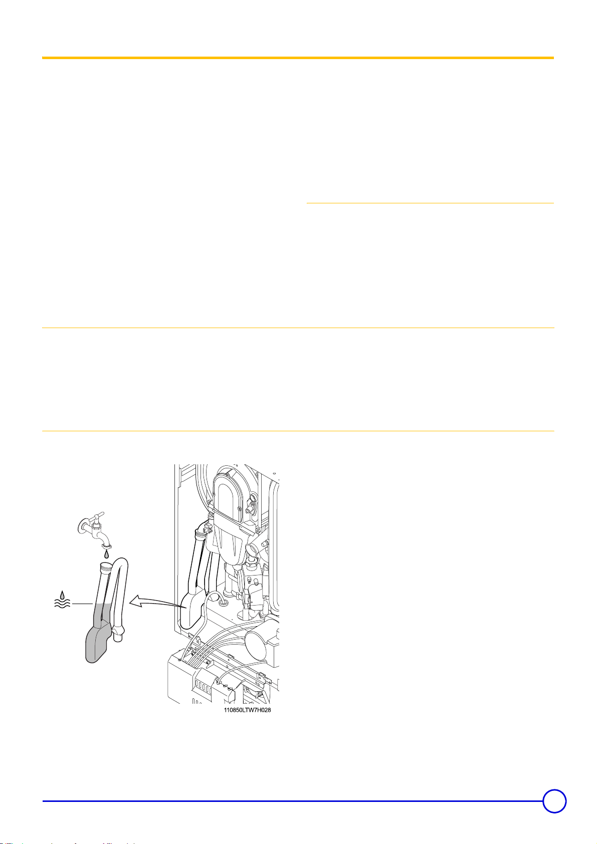
1.3 Filling the siphon
products will overflow into the waste water discharge
network.
To do this, fill the siphon with water via the combustion products
discharge conduit until it overflows.
Operation while the condensation water siphon is empty
may damage the boiler. There is a danger that combustion
08/06/06 - 300008460-001-B MCR 24, 24/28 MI, 30/35 MI, 34/39 MI
19
Page 20

1.4 Stove fitting connections
- Horizontal flue gas conduits must be installed with a zero gradient. The
run-off of condensates to the boiler is handled by the eccentricity of the
horizontal terminal. The terminal must be oriented according to the
figure below.
Use the mounting template provided with the boiler to position
holes to be drilled for the outlet of the horizontal forced flue.
- Static test overpressure : 1000 Pa
- Maximum leak rate : 50 l/hm2 depending on the internal surface
of the flue gas pipe
- A diameter 60 = 0.18 m
- A diameter 100 = 0.31 m
2
/m, A diameter 80 = 0.25 m2/m,
2
/m, A diameter 130 = 0.40 m2/m.
`On concentric (forced flue) flue gas evacuation systems, the
CO2 content in the annular space on the measurement pipe
can also be checked. The installation of the flue gas evacuation
is considered leak tight if the CO2 content measured is less
than 0.2%.
The cross section of the ventilation inlet in the premises for type B
connections (i.e. intake of combustive air into the premises) must be
in compliance with the prevailing standard.
- Type C appliances can only be installed with the systems
mentioned in these technical instructions (particularly concentric
pipes, terminal connection parts).
- As connections of type B
chimney conduits and type C
23
conduits are pressurised, they must be either installed outside or
in a ventilated brick sheath.
Ventilation must be ensured :
- by an opening located in the lower section, taking the air either
from the common ventilated areas or directly from outside, and
- by an opening in the upper section connected directly with the
outside.
The minimum cross section of the air vent and the openings to be
provided must be 100 cm
2
(clear cross section).
The parts of this sheath which can be dismantled must allow for
inspection of the flue gas conduit along its entire length.
Belgium
: The boiler installation and gas connection must be carried out
by a qualified professional in compliance with the NBN D 51.003, NBN D
30.003, NBN B 61.001, NBN B 61.002 and NBN D 51. 006 standards.
23
53
110850LTW7H030
Comply with the installation instructions and the information on the
authorised lengths of the flue gas pipes.
`Mount the flue gas pipe or the fresh air/flue gas evacuation
system in compliance with the assembly instructions.
`Check the tightness of the flue gas pipe.
20
MCR 24, 24/28 MI, 30/35 MI, 34/39 MI 08/06/06-300008460-001-B
Page 21
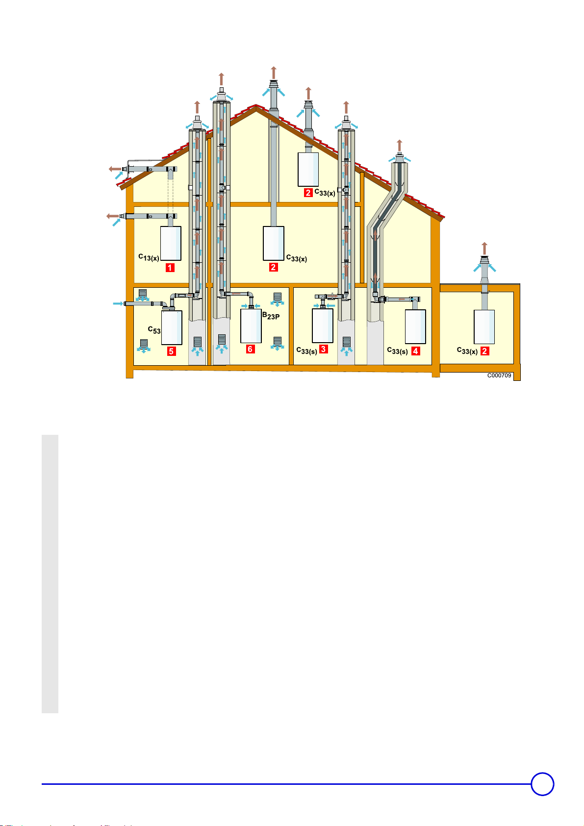
1.5 Classification
(s) Valid only for Belgium
(x) For Germany only
1 Homologation C
concentric pipes to a horizontal terminal (so-called forced flue)
2 Homologation C
concentric pipes to a vertical terminal (roof outlet)
or
3 Air/flue gas connection by concentric pipes in the boiler room and
single pipes in the chimney (combustive air in counter current in the
chimney)
or
4 Air/flue gas connection by concentric pipes in the boiler room and
single "flex" in the c himney (combustive air in counter current in the
chimney)
For Belgium:
Homologation C
connecting the boiler and the terminal. The clear section must
comply with the standard. The chimney must be swept before the
installation of the evacuation conduit.
5 Homologation C
means of a bi-flow adapter and single pipes (combustive air taken
from outside)
6 Homologation B
from the boiler room)
7 Homologation B
: Air/flue gas connection by means of
13(x)
: Air/flue gas connection by means of
33(x)
: Only factory components are authorised for
33(s)
: Air and flue gas connection separated by
53
: Chimney connection (combustive air taken
23P
: Cascade installation
23P
08/06/06 - 300008460-001-B MCR 24, 24/28 MI, 30/35 MI, 34/39 MI
21
Page 22

1.6 Lengths of the air/flue gas pipes
Type of air/flue gas connection Maximum length of the connection pipes (metres)
MCR 24 MCR 24/28 MI MCR 30/35 MI MCR 34/39 MIDiameter
Concentric pipes connected to a horizontal
terminal ((Alu))
Concentric pipes connected to a vertical
terminal ((Alu))
Concentric pipes in the boiler room
Single pipes in the chimney (combustive air in
counter current) ((Alu))
Concentric pipes in the boiler room
"Flex" pipes in the chimney (combustive air in
counter current) (PPS)
Bi-flow adapter + Separate single air/flue gas
pipes (combustive air taken from outside)
((Alu))
Chimney (rigid or flexible) (combustive air
taken in the premises) (PPS)
C
13(x)
C
33(x)
C
33(s)
C
33(x)
C
33(s)
C
33(x)
C
53
B
23P
60/100mm 6 7 4 6
80/125 mm 31 32 22 29
60/100mm 6 7 4 6
80/125mm 31 32 22 29
60/100 mm 80 mm
(rigid)
80/125 mm 80 mm
(rigid)
60/100 mm 80 mm
(flexible)
80/125 mm 80 mm
(flexible)
60/100mm
2x80 mm
80 mm (rigid) 33 37 19 22
80 mm (flexible) 23 27 22.5 24.5
18 23.5 10 12
- - 24 25.5
15.5 19 7 9
- - 18 20
44 48 30 32.5
(s) Valid only for Belgium (x) For Germany only
Lmax is measured by adding the lengths of the air/flue gas pipes and the equivalent lengths of the other elements.
Length of the reductions (Alu) (m) Ø 60/100 Ø 60 Ø 80/125 Ø 80
Elbow87° 1.1 1.1 1.0 1.2
Elbow45° 0.8 0.6 0.8 0.9
Elbow30° 0.7 0.9 0.6 0.6
Elbow15° 0.5 0.6 0.4 0.3
Inspection T 2.2 2.9 2.1 2.8
Right inspection tube 0.7 0.3 0.7 0.5
Length of the reductions PPS (m) Ø 60/100 Ø 60 Ø 80/125 Ø 80
Elbow87° 1.1 1.1 1.5 1.2
Elbow45° 0.8 0.6 1.0 1.4
Elbow30° 0.7 0.9 - 0.6
Elbow15° 0.5 0.6 0.4 0.3
Inspection T 2.2 2.9 2.6 2.8
Right inspection tube 0.7 0.3 0.6 0.5
Inspection tube for flexible pipe - - - 0.3
Belgium
:Boilers can only be installed with the stove fittings provided by the constructor. For the list of parts, refer to the current price list.
1.7 Assembly horizontal or vertical forced flue and forced flue accessories
Refer to the instructions delivered with the package.
Z
22
MCR 24, 24/28 MI, 30/35 MI, 34/39 MI 08/06/06-300008460-001-B
Page 23

• Horizontal forced flue Ø 60/100 mm (type C
Connection to an outside wall or roof outlet.
connection)
13x
A Flue gases
B Combustive air
• Connection C
- Concentric vertical forced flue
33x
Connection to a sloping or flat roof.
A Flue gases
B Combustive air
08/06/06 - 300008460-001-B MCR 24, 24/28 MI, 30/35 MI, 34/39 MI
23
Page 24

• Connection C
33x
( C
: For Belgium) - Concentric pipes in the boiler room - Single pipes in the chimney (combustive air in
33s
counter current)
Discharge via conduit, fresh air in counter current.
A Flue gases
B Combustive air
C Horizontal section (Maximum length 1 m)
• Connection C
counter current)
33x
( C
: For Belgium) - Concentric pipes in the boiler room - Inspection tube for flexible pipe (combustive air in
33s
24
MCR 24, 24/28 MI, 30/35 MI, 34/39 MI 08/06/06-300008460-001-B
Page 25

• Separate air and flue gas connection Ø 60/100 mm over 2xØ80 mm (type C53 connection)
A Ventilation (100 cm2 minimum)
B Casing classified (M1)
C Leak proof rose
D Inspection hatch
E Openings (5 0 cm2)
• Connection to a chimney Ø 80 mm type B23 connection)
Chimney conduit fitting into a chimney, combustive air taken in the
premises.
A Flue gases
B Horizontal section (max 1 m)
C Chimney connection kit
D Combustive air
08/06/06 - 300008460-001-B MCR 24, 24/28 MI, 30/35 MI, 34/39 MI
25
Page 26

1.8 Electrical connection (230 V)
The boilers are delivered pre-fitted with a 3-conductor power supply
cable with an available length of around 1.5 metres.
The appliance must be powered by a circuit containing an omnipolar
switch with an opening distance 3 mm.
Only qualified professionnals may carry out electrical
connections, always with the power off.
When connecting to the mains, be sure to respect live for the brown
wire, neutral for the blue wire and earth for the green/yellow wire.
For Belgium + Certain European countries
If you use a two-phase electrical grid, jumper must be removed
(130 V: Lane/Neutral).
The boiler is not sensitive to phase reversal.
26
MCR 24, 24/28 MI, 30/35 MI, 34/39 MI 08/06/06-300008460-001-B
Page 27

2 Connecting the options
Optional equipment can be connected to the connectors on the
control panel.
`Tilt the flap on the control panel.
`Open the protective hood.
`Make the connections according to the optional equipment you
are using.
Programmable room temperature thermostat (Package AD
137) or Wireless settable ambient thermostat (Package AD
200) or Non settable ambient thermostat (Package AD 140).
Refer to the instructions delivered with the thermostat.
Z
Outside sensor (Package AD 225)
Refer to the instructions delivered with the package.
Z
Communicating remote controller: Easymatic (Package FM
50) or Easyradio (Package AD 201) with or without external
sensor (Package AD 225) + Interface PCB (AD 221)
The connection can be made either by a 2-wire telephone
cable, or by an electric cable with a cross-section that may be
up 2 x 1.5 mm
Refer to the instructions delivered with the package.
Z
2
.
Underfloor heating: Easymatic (FM 50)/Easyradio (AD 201) +
Outside sensor (AD 225) + Interface PCB (AD 222)
Refer to the instructions delivered with the package.
Z
If you have underfloor heating: Connect the security thermostat
in the external electrical connection box (See: Package AD
222).
Accessories
- Stand of frame (Package HG19)
- Pipework kit for stand of frame (Package HG20)
- Cover pipes (Package HG21)
- Replacement kit (ELM - Package HG23); (Saunier Duval Package HG24); (Chaffoteaux et Maury - Package HG25);
(Vaillant - Package HG26)
- Mounting frame + Disconnector (Package HG27)
Standard delivery. Possibility of separate orders for the preinstallation.
- Neutralisation station (Package HC33)
- Wall support (Neutralisation station) (Package HC34)
- 2 kg refill to neutralisation (Package HC35)
- Flow collector (For Belgium+Poland)
Refer to the instructions delivered with the package.
Z
08/06/06 - 300008460-001-B MCR 24, 24/28 MI, 30/35 MI, 34/39 MI
27
Page 28

3 Connecting the external controls
- Unscrew the 2 screws.
- Remove the front panel of the cladding.
- Run the cables in the cable clamps.
- Connect the cables to the connectors (See drawing opposite).
Switch off the mains electricity supply before carrying out
any work.
28
MCR 24, 24/28 MI, 30/35 MI, 34/39 MI 08/06/06-300008460-001-B
Page 29

3.1 ON/OFF room thermostat
: Existing bridge
: Cable BUS: AD 221 or AD 222
MCR boilers can be connected to a 2-wire on/off room thermostat.
Choose a location in a "reference" room representative of the
room temperature to be taken into account if the remote control is
used as a room sensor.
1. Lane 230 V - Intensity in Amperes: 3
2. Power supply - Neutral
3. Common alarm (Contact closed)*
4. Boiler in use (Contact open)*
5. Neutral
6. Tap open: DHW
7. Tap open: Heating
8. Outside sensor connection
9. Connecting the tank sensor (Remove bridge)
10. Boiler blockage input (Remove bridge)
11. Existing bridge
12. Cable BUS: AD 221 or AD 222 (Remove bridge)
13. Not connected
14. Switch: Domestic hot water (To use this function, remove the
bridge between terminals 4 and 3)
15. Existing bridge. To be used when room thermostat is connected.
16. Switch: Heating (To use this function, remove the bridge between
terminals 4 and 1)
*Depending on parameter settings
Connect terminals 7 and 8 on the thermostat to the terminals on
connector X9.
If you are using a room thermostat with anticipation resistance,
parameter P5 must no longer be defined as 0 but as 1.
08/06/06 - 300008460-001-B MCR 24, 24/28 MI, 30/35 MI, 34/39 MI
29
Page 30

3.2 Easymatic,Easyradio regulation connection
: Existing bridge
: Cable BUS: AD 221 or AD 222
Modulating thermostats can be connected without further adaptation.
Choose a location in a "reference" room representative of the
room temperature to be taken into account if the remote control is
used as a room sensor.
- Connect the regulation on the interface PCB (J7).
- Connect connector J6 to the interface PCB on the X9 connector.
Refer to the instructions delivered with the package.
Z
3.3 External temperature probe connection
: Existing bridge
: Outside sensor connection
An outside temperature sensor can be connected to connectors 1
and 2 on terminal X9.
(Adjustment parameter P27, from 0 to 60°C)
- Outlet temperature setting point at a minimum outside temperature
= 20 °C
(Adjustment parameter P1, from 20 to 85°C)
: Factory setting
The boiler will regulate output using the setting point on the internal
heating curve:
- Minimum temperature setting point = -15 °C
(Adjustment parameter P29, from 0 to -30°C)
- Maximum temperature setting point = 20 °C
(Adjustment parameter P28, from 0 to 40°C)
- Outlet temperature setting point at a maximum outside
temperature = 20 °C
30
MCR 24, 24/28 MI, 30/35 MI, 34/39 MI 08/06/06-300008460-001-B
Page 31

4 Connection of the domestic hot water sensor
: Existing bridge
: Connecting the tank sensor
5 Antifreeze protection
If an external domestic hot water tank is used with the MCR boiler,
the probe without power from the domestic hot water tank can be
connected to connectors 3 and 4 of terminal block X9.
The control unit automatically detects the presence of an external
sensor.
- When the water temperature is above 10 °C, the boiler is switched
off and the circulation pump runs for another 15 minutes.
If a room thermostat, connected via connectors 7 and 8, is
activated, the boiler will operate permanently until it
reaches the outlet setting point.
: Existing bridge
: Cable BUS: AD 221 or AD 222 or Thermostat ON/OFF
MCR boilers must be installed in a frost-free environment
If the temperature of the central heating water in the boiler falls too
much, the integrated protection device switches itself on:
- If the water temperature is lower than 7°C, the circulating pump is
activated,
- If the water temperature is lower than 3°C, the boiler is activated,
08/06/06 - 300008460-001-B MCR 24, 24/28 MI, 30/35 MI, 34/39 MI
31
Page 32

6 Safety contact
: Existing bridge
: Safety contact
7 Connection of a remote alarm transfer and boiler operation indication system (Not proposed)
The boiler is equipped with a 3 pin connector without power on
terminal block X7. The terminal block can be used to connect to an
external gas valve, a remote alarm transfer and boiler operation
indication system.
- Connect the alarm transfer system to pins 1 and 2 of terminal block
X7. Contact is closed in the event of a shutdown.
To do so: Set parameter 24 to 1.
- Connect the boiler operation indication system to pins 1 and 3 of
terminal block X7. If heating is required, the boiler thermostat
closes the contact.
To do so: Set parameter 24 to 2.
- Connect an external gas valve to pins 1 and 3 of terminal block X7.
The contact is closed when the gas valve is activated.
To do so: Set parameter 24 to 3.
MCR boilers are equipped with a security switch. A voltage-free
switching device (e.g. an external gas pressure switch or a safety
thermostat for underfloor heating) can be connected to connectors 5
and 6 on terminal X9 after disconnecting all of the cables. When the
contact is open, the boiler turns off indicating code 9; it will start again
once the contact is closed.
: Common alarm (Contact closed)
: Boiler in use (Contact open)
32
MCR 24, 24/28 MI, 30/35 MI, 34/39 MI 08/06/06-300008460-001-B
Page 33

8 Pump logic
-In mode (domestic hot water) or with Easymatic in
(Summer), the pump operates during the production of domestic
hot water. With an Easymatic, the pump shuts down after the pump
flow switch-off delay. The heating/domestic hot water reversal
valve remains in the DHW position.
- With room temperature thermostat
- The pump switches off 2 minutes after the contact with the room
temperature thermostat is opened. After the production of
domestic hot water, if the room temperature thermostat is open,
the pump switches off after 5 seconds and the heating/domestic
hot water reversal valve remains in the DHW position.
With Easymatic or Easyradio
- When the desired room temperature is not reached, the pump
operates continually. When the room temperature is too high, the
pump is shut down after the pump switch-off delay (See
"Easymatic"). If the room temperature is too high after domestic hot
water production, the pump shuts down after the pump switch-off
delay; the heating/DHW reversal valve remains in the DHW
position (See "Easymatic").
- Easymatic and outside temperature sensor or Outside sensor
alone
Refer to the instructions delivered with the package.
Z
- If necessary, when the boiler temperature falls below 10°C, the
pump starts up to ensure that the boiler is protected from frost.
#
mode
08/06/06 - 300008460-001-B MCR 24, 24/28 MI, 30/35 MI, 34/39 MI
33
Page 34

The first start-up is to be performed by your installation
engineer.
1 Commissionning
Commissionning
The boiler is preset in the factory to operate on natural gas. Operating
pressure: 20 mbar.
For Belgium: Operating pressure: 25 mbar.
1.1 Final checks before commissioning
The first start-up is to be performed by your installation
engineer.
Before start-up, the heating installation must be completely emptied
and rinsed.
Fill the installation with water.
Check that the equipment is properly set for the type of gas
used.
For Belgium: Any intervention on the gas valve unit is
strictly forbidden.
Cut the power supply to the boiler
Unscrew the 2 screws.
Remove the front panel.
Disconnect the 2 ignition electrodes from the connector/ignition on
the gas valve.
34
MCR 24, 24/28 MI, 30/35 MI, 34/39 MI 08/06/06-300008460-001-B
Page 35

1.2 Water and gas connections
First check that the water is circulating in the boiler (water pressure
in the heating circuit, outlet and return valves open, valves and
radiators open, etc.).
Opening the valve
Measuring point on the gas block (C)
Open the gas valve.
Checking the gas supply pressure: Measurement point C.
Recommended pressure: See "Certifications".
Z
Carry out a gas tightness check. Maximum pressure: 60 mbar.
For Belgium: Maximum pressure: 100 mbar.
Open the valves on all radiators connected to the heating system.
Fill the installation with water (Minimum pressure: 1 bar, Maximum
pressure: 2.5 bar).
When filling, air may escape from the system via the automatic air
bleed and the pump.
Use the bleed plugs provided, which are attached to the gas
valve unit in the event of water leakage.
Do not allow water to get into the boiler.
Check the condensates discharge siphon; it must be filled with clean
water up to the mark.
Check the boiler pump. Remove the central chrome screw to bleed
the pump.
Carry out a water tightness check.
Bleed the gas supply pipe by unscrewing the measuring point on the
gas valve unit. Tighten the measuring point when the pipe has been
sufficiently bled.
Check the seals on the gas and water connections.
Check the electrical connections.
08/06/06 - 300008460-001-B MCR 24, 24/28 MI, 30/35 MI, 34/39 MI
35
Page 36

Check the electrical connections to the thermostat and the other
external controls. Checking tightness (hydraulics, combusted gas
discharge and gas).
1.3 Switching the boiler on
Turn the boiler on (230 V).
Set the boiler regulation according to the heating request.
The boiler will begin an automatic venting-programm (which lasts
approx. 3 minutes) and will do this every time the power supply is
isolated.
The boiler is now ready to operate. The current operating status is
shown on the display. The display shows O.
1.4 Setting the gas/air ratio (Full load)
Belgium: Any intervention on the gas valve unit is strictly
forbidden.
Values: Setting
Boiler type Fan speed (rpm)* CO2 (%) CO2 (%)
Full load H:3
Natural gas Propane Natural gas Propane
24 ca. 4600 ca. 4400 8.8 ±0.1 10.5 ±0.3
24/28MI ca. 5500 ca. 5200 8.8 ±0.1 10.5 ±0.3
30/35MI ca. 6300 ca. 6000 8.8 ±0.1 10.5 ±0.3
34/39MI ca. 6700 ca. 6400 8.8 ±0.1 10.5 ±0.3
*In the event of forced operation at low speed, the second figure indicates
the operating code.
Unscrew the flue gas requirement plug.
Connect the combusted gas analyser.
Set the boiler to full load.
Press the key. The display shows H:3: The full load is set.
Measure the O
If this rate does not match the parameter value, correct the gas/air
ratio using the adjustment screw A on the gas valve unit.
If the rate is too high, turn the screw A clockwise to reduce the gas
flow.
If the rate is too low, turn the screw A anti clockwise to increase the
gas flow.
Check the flame via the flame detection cell. It must not go out.
Check that the analysis probe is leakproof against gas at the
sampling level point, the extremity of the probe is in the centre
of the smoke evacuation pipe.
or CO2 content in the flue gases.
2
The boiler is preset in the factory to operate on natural gas.
36
MCR 24, 24/28 MI, 30/35 MI, 34/39 MI 08/06/06-300008460-001-B
Page 37

1.5 Setting the gas/air ratio (Part load)
Values: Setting
Boiler type Fan speed (rpm)* CO2 (%) CO2 (%)
Part load: L:3
Natural gas Propane Natural gas Propane
24 ca. 1300 ca. 2000 8.8 ±0.1 10.5 ±0.3
24/28MI ca. 1300 ca. 2000 8.8 ±0.1 10.5 ±0.3
30/35MI ca. 1300 ca. 2000 8.8 ±0.1 10.5 ±0.3
34/39MI ca. 1300 ca. 2000 8.8 ±0.1 10.5 ±0.3
Set the boiler to part load.
Press the - key until the L:3 symbol is displayed: The part load is set.
Measure the O
If this rate does not match the parameter value, correct the gas/air
ratio using the adjustment screw B on the gas valve unit.
If the rate is too high, turn the screw B clockwise to reduce the gas
flow.
If the rate is too low, turn the screw B anti clockwise to increase the
gas flow.
or CO2 content in the flue gases.
2
1.6 Final checks before commissioning
Remove the analysis sensor
Replace the plastic plug onto the measuring tube.
Put the upper front panel in place. Tighten the screws
To return to normal configuration, press briefly on button .
if you do not press any keys, return to normal confiuration after
15 minutes.
Check the water pressure in the installation. Top up with more water
if necessary.
.
.
Check the flame via the flame detection cell. It must not go out.
Check that the analysis probe is leakproof against gas at the
sampling level point, the extremity of the probe is in the centre
of the smoke evacuation pipe
Repeat the high speed test and the low speed test as often as
necessary until the correct values are obtained without having to
make additional adjustments.
08/06/06 - 300008460-001-B MCR 24, 24/28 MI, 30/35 MI, 34/39 MI
37
Page 38

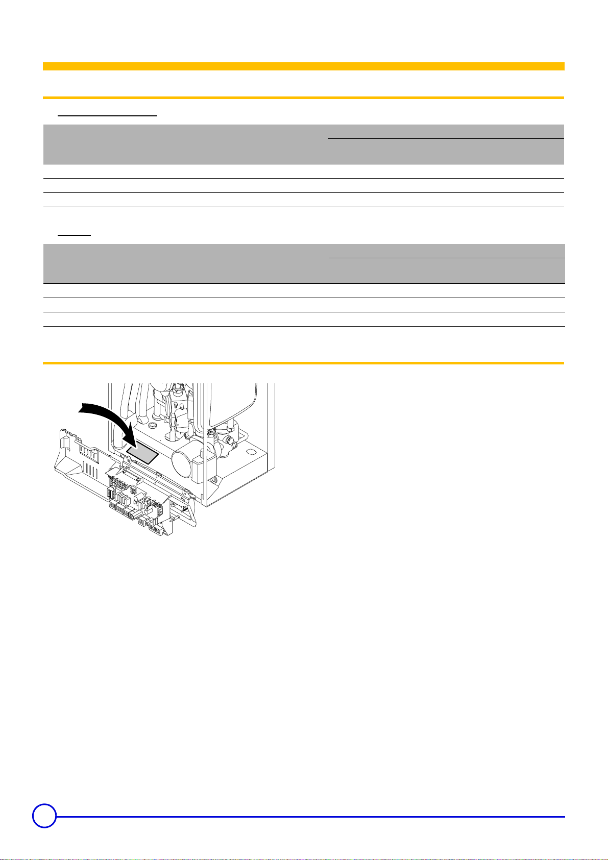
Write down the type of gas on the sticker on the inside of the flap.
38
MCR 24, 24/28 MI, 30/35 MI, 34/39 MI 08/06/06-300008460-001-B
Page 39

2 Commissioning
• Switch on the boiler. Activate the main switch in the installation.
• Commissioning cycle
Screen display:
- F XX: Software version
• The boiler will begin an automatic venting-programm (which
lasts approx. 3 minutes) and will do this every time the power
supply is isolated. The version numbers are displayed
alternately.
- P XX: Parameter version
The current operating status is shown on the display:
Heating only: production of domestic hot water:
1: Fan ON 1: Fan ON
2: Boiler is igniting 2: Boiler is igniting
3: Operation: Heating mode 4: Operation: Domestic hot water mode
Heating only: condition satisfactory production of domestic hot water: condition satisfactory
1: Post-ventilation 1: Post-ventilation
6: Pump operation (Heating mode) 7: Pump operation (Domestic hot water mode)
0: Stand-by 0: Stand-by
2.1 Display
• No display:
- Check that the boiler is switched on (230 V),
- Check the electrical connections,
- Check the fuse (F2 = 2 AT, 230 V).
• Breakdown codes:
- The symbol
m
flashes,
- A malfunction code indicates the nature of the breakdown (for
E10
example:
),
- Correct the error if possible,
- Press key
After an E1, E2, E7, E10 or E13 error, the 3-minute air venting
cycle will take place before the boiler starts up.
for 2 seconds: The boiler restarts.
2.2 Parameter display (See "Control panel")
2.3 Boiler setting
• "User" settings
Parameters P1 to P6 can be modified by the user in order to meet
central heating and DHW comfort needs.
• "Installer" settings
Parameters P17 to dF must only be modified by a qualified
professional.
08/06/06 - 300008460-001-B MCR 24, 24/28 MI, 30/35 MI, 34/39 MI
39
Page 40

2.4 Setting different parameters (with access code)
To get acces to the error memory, the acces code 12 must be
entered.
Parameter Description Comments Factory setting
P17 Maximum ventilator speed
(Heating)
P18 Maximum ventilator speed (DHW) Do not modify 46 55 63 67
P19 Minimum ventilator speed
(Heating+DHW)
P20 Start up speed for the ventilator Do not modify 25 25 28 30
P21
P22 Operating time: Pump (Heating) 1 to 99minutes 2
P23 Connection with the heat
P24
P25
P26 DHW cut-in temperature 2 to 15 °C 5
P27 Heat curve set point: Flow
P28 Heat curve set point: Outside
P29 Heat curve set point: Outside
P30
P31 Temperature, for which the
PdF (PdU)
Setting the pump speed
recuperation unit
Remote alarm
(Terminal X7)
The regulator includes legionella
protection function, that can be
actived
temperature
temperature (Max)
temperature (Min)
Boiler type
production of domestic hot water
is stopped, exceeded
Factory setting
10-70
X 100 rpm
Do not modify
0 = Part load
1 = Full load
0 = No connection
1 = Connection
0 = Stop "OFF" (Connectors 1 and 2 closed)
1 = Alarm messages (Connectors 1 and 3 closed)
2 = Operating light (Connectors 1 and 3 closed)
3 = External gas valve (Connectors 1 and 3
closed)
0 = Stop
1 = Start
2 = Automatic (After commissioning, the boiler will
operate once a week at 65°C for DHW) 1000
0 to 60 °C
0 to 30 °C
-40 to 0 °C
0 = MCR 1024
1 = MCR ... Combi (Heating only)
0 to 20 °C
Parameter dFX appears on the identification
plate; if this parameter is set as X, the factory
parameters will be reinstated
Parameter dUY appears on the identification
plate; if this parameter is set as Y, the factory
parameters will be reinstated
Adjustment must be done by a qualified professional.
24 24/28 MI 30/35 MI 34/39 MI
37 37 41 47
13 13 13 13
0
0
0
20
20
-15**
1 0 0 0
15
X
Y
**The character - is not displayed.
40
Modification of the factory parameters may be detrimental
to the functioning of the boiler.
MCR 24, 24/28 MI, 30/35 MI, 34/39 MI 08/06/06-300008460-001-B
Page 41

2.5 Modify parameters
• MCR 24
• MCR 24/28 MI
- Press the Ä key until the symbol is displayed.
- Select the fitter menu using the l key. The symbol COdE
appears.
- Enter the fitter code 0012 using the - or + key.
- To confirm, press the l key. The symbol P:1 appears.
- Press the l key a second time. The symbol 75°C appears
(Factory setting).
- Lower the value to 60°C using the - key.
- To confirm, press the l key
- To confirm, press the l key. The symbol P:1 appears.
- If necessary, set other parameters by selecting them using the - or
+ keys.
- Press key 2 time to return to the current operating mode.
If no selections are made in the various modes for 10 minutes,
the boiler resumes the settings prior to manipulation.
• MCR 30/35 MI, MCR 34/39 MI
X: Boiler power (kW)
Y: Fan rotation speed (rpm)
2.6 Setting the maximum output (Hi): Heating
Parameter P17 (maximum fan speed) is used to modify maximum
central heating output.
Fan speed/boiler output ratio
08/06/06 - 300008460-001-B MCR 24, 24/28 MI, 30/35 MI, 34/39 MI
41
Page 42

2.7 Return to the factory settings "Reset Param"
2.8 Manual operation ()
- Press the + key until the P:dF symbol is displayed.
- Press the l key. The symbol dF:X appears.
To reinstate the factory settings, enter the value X using the - or +
key.
- Press the l key. The symbol dU:Y appears.
To reinstate the factory settings, enter the value Y using the - or +
key.
- To confirm, press the l key.
- Press key Ä several times until the symbol flashes on the
menu bar.
- Press the l key. The symbol AUtO appears (if outside sensor
connected).
The outlet temperature is determined by the internal heating curve.
Minimum outlet temperature: Press the + key to modify the setting.
- To confirm, press the l key.
The installation is in manual mode.
- Press key 1 time to deactivate the manual mode.
42
MCR 24, 24/28 MI, 30/35 MI, 34/39 MI 08/06/06-300008460-001-B
Page 43

2.9 Switching off
Before any work is carried out on the equipment / heating system, the
power supply must be disconnected (by means of the appropriate
fuse or main switch, for example) and warning must be given before
any reconnection.
2.10 Antifreeze protection
We recommend setting the boiler thermostat to a value lower than
10°C if using a classic installation.
Define parameter P4 as 1 (energy-saving mode); the heat retention
function will be deactivated.
Installation and room antifreeze protection is guaranteed if you are
absent.
2.11 If the central heating system is not used for a long
period, we recommend switching the boiler off
Switch the boiler off.
Cut the power supply to the boiler.
Cut the gas supply.
08/06/06 - 300008460-001-B MCR 24, 24/28 MI, 30/35 MI, 34/39 MI
43
Page 44

Adapting to another gas
For Belgium: Only SERV’élite is authorised to carry out the
conversion of this appliance.
MCR boilers are preset in the factory for natural gas H.
The actions described below must be carried out by a
qualified technician.
1 Switching from Natural Gas to Propane
The conversion from Natural Gas to Propane requires only the
adjustment of the burner and the fan speed.
2 Setting the control unit parameters
For conversion to propane
To obtain the gas valve setting used to start up with propane, use the
following instructions:
- GN (G20) to G31: Turn the high speed adjustment screw 2
rotations clockwise
or
- Turn high speed screw clockwise until it is closed. Turn high speed
adjustment screw 3.5 - 4 rotations counter clock wise.
Parameter Nominal fan
speed
(rpm)
MCR 24
Natural gas H
(Factory setting :
Gn by default)
Propane (Factory
setting : Pr)
Nominal power
h3
Minimum output
L3
Maximum DHW
speed
H3
Nominal power
h3
Minimum output
L3
Maximum DHW
speed
H3
P17 3700 3700 4100 4700 8.8±0.3
P19 1300 1300 1300 1300 8.8±0.3
P18 4600 5500 6300 6700 8.8±0.3
P17 3500 3500 3900 4500 10.5±0.3
P19 2000 2000 2000 2000 10.5±0.3
P18 4400 5200 6000 6400 10.5±0.3
For Belgium: The boiler installation and gas connection
must be carried out by a qualified professional in
compliance with the NBN D 51.003, NBN D 30.003, NBN B
61.001, NBN B 61.002 and NBN D 51.006 standards.
After this setting, the boiler will not have an optimum setting for
propane.
For the precise setting, use a CO
measuring device and apply the
2
settings procedures:
See "Modify parameters" and "Setting the gas/air ratio - Full
Z
load + Part load"
Nominal fan speed
(rpm)
MCR 24/28MI
Nominal fan
speed
(rpm)
MCR 30/35MI
Nominal fan
speed
(rpm)
MCR 34/39MI
CO
2
%
44
MCR 24, 24/28 MI, 30/35 MI, 34/39 MI 08/06/06-300008460-001-B
Page 45

2.1 Adjusting the gas valve
110850LTW7H030
See "Setting the gas/air ratio".
08/06/06 - 300008460-001-B MCR 24, 24/28 MI, 30/35 MI, 34/39 MI
45
Page 46

Maintenance
MCR boilers require little maintenance. An annual inspection is
compulsory.
Maintenance operations must be done by a qualified
professional.
If, on annual inspection, the combusted gas analysis is not in
compliance, a setting combustion operation must be carried
out.
1Inspection
Cut the power supply to the boiler.
Cut the gas supply to the boiler.
If the ionisation current is less than 3, check the ignition/
ionisation electrode as well as the ignition line and the earth
connection.
Only original spare parts must be used.
1.1 Checking the hydraulic pressure
46
Minimum pressure: 1 mbar. Add water to the installation if necessary.
Carry out a visual check for the presence of any water leaks.
MCR 24, 24/28 MI, 30/35 MI, 34/39 MI 08/06/06-300008460-001-B
Page 47

1.2 Check the fresh air inlet and flue gas discharge ducts
(or the forced flue)
1.4 Checking the ignition electrode
The conduits must allow no leakage of flue gases and be resistant to
corrosion.
1.3 Checking condensates discharge (Siphon)
- Wipe off all traces of deposits using an abrasive cloth.
- Check the gap between the electrodes (3 to 4 mm).
- Check the leak proof seal.
- Check the ionisation current. If the ionisation current is less than
3µA, check the ignition/ionisation electrode as well as the ignition
line and the earth connection.
- Refit the ignition electrode .
The ignition cable is fixed to the ignition electrode and therefore
may not be removed.
Check the condensates discharge siphon; it must be filled with clean
water up to the mark.
08/06/06 - 300008460-001-B MCR 24, 24/28 MI, 30/35 MI, 34/39 MI
47
Page 48

1.5 Checking combustion
Measure the content of O
/CO2 and the burnt gas temperature at the
2
flue gas sampling level point.
- Unscrew the upper part of the flue gas measuring point.
- Measure the O2 or CO2 content in the flue gases.
Check that the analysis probe is leakproof against gas at the
sampling level point, the extremity of the probe is in the centre
of the smoke evacuation pipe.
Values: Checks (Natural gas H
Boiler type
24 ca. 4600 ca. 1300 8.8 ±0.3 9.5 ±0.3
24/28MI ca. 5500 ca. 1300 8.8 ±0.3 9.5 ±0.3
30/35MI ca. 6300 ca. 1300 8.8 ±0.3 9.5 ±0.3
34/39MI ca. 6700 ca. 1300 8.8 ±0.3 9.5 ±0.3
Boiler type Fan speed (rpm)* CO2 (%)
24 ca. 4400 ca. 2000 10.5±0.3
24/28MI ca. 5200 ca. 2000 10.5±0.3
30/35MI ca. 6000 ca. 2000 10.5±0.3
34/39MI ca. 6400 ca. 2000 10.5±0.3
Full load H:3 Part load L:3
Fan speed (rpm)*
Values: Checks (Propane)
Full load H:3 Part load L:3
If the measured values differ from those given in the table, an
adjustment is necessary. Check the setting of the gas/air ratio and, if
necessary, correct it.
If you still do not manage to reach the values indicated, a
complete service of the boiler is required.
See "Maintenance".
Check the flame through the viewport; it must be stable and
blue in colour, with orange particles around the edges of the
burner (Full load).
CO2 (%)
For Belgium
CO2 (%)
48
MCR 24, 24/28 MI, 30/35 MI, 34/39 MI 08/06/06-300008460-001-B
Page 49

2 Maintenance
Cut the power supply to the boiler.
Cut the gas supply to the boiler.
2.1 Open
Unscrew the 2 screws.
Remove the front panel. Disconnect the 2 ignition electrodes from
the connector/ignition on the gas valve (
).
2.3 Remove the front plate from the combustion chamber
Disconnect the ignition electrode from the transformer.
Disconnect the electrical connection from the gas valve unit.
Remove the gas block connection nut.
Disconnect the electrical connection to the fan.
Remove the nuts from the inspection hatch on the front of the heat
exchanger.
Then remove the inspection hatch, the fan and the gas valve unit.
2.2 Checking the ignition electrode / ionisaton sensor
- Dismantle the electrode pin and the earth cable.
- Unscrew the 2 screws. Remove the unit.
- Clean or replace the ignition electrodes.
08/06/06 - 300008460-001-B MCR 24, 24/28 MI, 30/35 MI, 34/39 MI
49
Page 50

2.4 Burner maintenance
Clean the burner with a brush, a vacuum cleaner or a blower.
Inspect the burner to detect any damage or cracks in the surface. If
the burner is damaged, replace it.
2.5 Maintenance of the heat exchanger
- Check the burner seal.
- Check the insulating component between the front plate and the
thermal exchanger.
A damaged or hardened seal must always be replaced.
Handle the front plate and the rear plate of the thermal
exchanger with care; they must not come into contact with
water.
- Descale the exchanger in order to maintain its performance levels.
- Clean the inside of the heat exchanger using a stiff brush
(optional).
50
MCR 24, 24/28 MI, 30/35 MI, 34/39 MI 08/06/06-300008460-001-B
Page 51

2.6 Cleaning the plate exchanger (for MCR ... MI)
Maintenance and cleaning of the heater must be carried out
at least once a year by a qualified technician.
Cut off the cold water supply and drain the DHW tank.
Bleed the boiler.
Unscrew the 2 screws.
Remove the exchanger.
Clean the plate heat exchanger with a descaling product (citric
acid pH 3). A special tool (accessory available as an option) can be
used (See:Spare parts centre).
Rinse with clean water.
Remove the flow switch. If necessary, clean or replace the
flow switch. Rinse with clean water.
Cut the power supply to the boiler.
08/06/06 - 300008460-001-B MCR 24, 24/28 MI, 30/35 MI, 34/39 MI
51
Page 52

2.7 Re-assembling the boiler
Follow in reverse order for re-assembly.
Do not forget to reconnect the fan connector before
reattaching the fan to the thermal exchanger.
Check that the leak proofing material between the front
plate and the thermal exchanger is correctly fitted.
Top up the installation with water.
Restart the boiler.
Measure the O
Check the ionisation current.
Check the seals on the gas and water connections.
or CO2 content in the flue gases.
2
52
MCR 24, 24/28 MI, 30/35 MI, 34/39 MI 08/06/06-300008460-001-B
Page 53

Electrical diagram
BK Black
BL Blue
BR Brown
GN Green
GN/YW Green/Yellow
GY Grey
RD Red
WH White
YW Yellow
08/06/06 - 300008460-001-B MCR 24, 24/28 MI, 30/35 MI, 34/39 MI
As Flow sensor
BP Boiler pump
Fs Flow switch
CP Pump
DV Inverter valve
GCV Gas valve
HLT Limiting thermostat
Os Outside sensor (optional)
Rs Return sensor
- - - - not supplied / Not connected
53
Page 54

1 Alarm code
Breakdown codes
In the event of a breakdown, the symbol m and a flashing code
are displayed.
Alarm
Description Probable causes Checks/Solution
Press key for 2 seconds. If the error code remains on the
screen, look for the nature of the error.
code
Check the wiring. Replace the protect ion caps . If a fau lty sensor i s de tected, it i s possible to
Outlet or return
E0
sensor error
Flow temperature >
Maximum operating
E1
temperature
Return temperature
E2
> Flow temperature
Short circuit
Faulty sensor
Sensor not or badly connected
The water level and/or pressure are
too low
No circulation
Too much air When the pump is switched off, vent the system
Deviation of the outlet or return
temperature sensor
The water level and/or pressure are
too low
No circulation
Too much air When the pump is switched off, vent the system
Sensor not or badly connected Check the wiring between the sensors and the control panel
Deviation of the outlet or return
temperature sensor
check the resistance at the various temperatures using a meauring device with a
corresponing measurement range (e.g. a multimeter)
Check that the sensors are operating correctly. If a faul ty sensor is det ected, it is possible t o
check the resistance at the various temperatures using a meauring device with a
corresponing measurement range (e.g. a multimeter)* (20 to 25°C). sensor resistance
values: 12 to 15 kOhm.
Check the water pressure in the installation (Pressure gauge)
Check that the boiler circulating pump is working. Insert a screwdriver into the slot in the
pump spindle and turn the spindle several t imes to the r ight an d left. Check t he wiring. If t he
pump still does not work, it is faulty and must be changed.
Check that the sensors are operating correctly. If a faul ty sensor is det ected, it is possible t o
check the resistance at the various temperatures using a meauring device with a
corresponing measurement range (e.g. a multimeter)* (20 to 25°C). sensor resistance
values: 12 to 15 kOhm.
*When the sensors have been removed, replace the sensors a maximum of 40 mm from the thermal exchanger of the copper pipes.
Operating diagrams: Temperature sensor/Resistance
Resistance in ohm
Temperature (°C)
Temperature sensor/Resistance-Operating diagrams
54
MCR 24, 24/28 MI, 30/35 MI, 34/39 MI 08/06/06-300008460-001-B
Page 55

Alarm
Description Probable causes Checks/Solution
code
Control panel: faulty
E3
Power supply cable:
faulty
No flame detection
(After a prolonged
E4
shutdown, up to 5
start-up attempts may
be made)
E5 Ionisation error
Detection of a parasite
E6
flame
Water pressure in the
E7
boiler:absence
Pump operation: Poor
Control panel: faulty
Power supply cable: faulty
Power supply cable badly
Check the electrical connections.
connected
- Check the ignition electrode (spacing of the electrodes), its connector and its
No spark from the electrode
connection cable
- Check the positioning of the electrode (gap: 3.5 mm)
- Check the earth
- First check that the gas valve is open, that the gas supply pressure is present, that
the gas conduit has been sufficiently bled, that the air/flue gas conduit is not blocked
Presence of a series of sparks
No flame detection
and is not leaking, that the siphon is full and not blocked
- If you use a two-phase electrical grid, jumper must be removed
- Clean or replace the ignition electrodes
- The CO
level at full load and part load
2
- Check the combustion and the stability of the flame,
Detection of a parasite flame
Ionisation error (<3µA or >9µA)
- The CO2 level at full load and part load
- Check the electrical connections, particularly the earth
- Clean or replace the ignition electrodes
- Check the positioning of the electrode (gap: 3.5 mm)
- Check the CO2 level in the gas valve unit
- Check the ignition electrode (spacing of the electrodes), its connector and its
Poor setting: CO
2
connection cable
- Check the concentric combusted gas evacuation and combustive air inlet pipes
- Check the high speed gas circulation,
Replace the control panel if it is faulty
The water level and/or pressure
are too low
Check the water pressure in the installation
Carry out a visual check for the presence of any water leaks
Check that the boiler circulating pump is working. Insert a screwdriver into the slot in
No circulation
the pump spindle and turn the spindle several times to the right and left. Check the
wiring. If the pump still does not work, it is faulty and must be changed.
Too much air When the pump is switched off, vent the system
Bad pump wiring Check the electrical connections
08/06/06 - 300008460-001-B MCR 24, 24/28 MI, 30/35 MI, 34/39 MI
55
Page 56

Alarm
Description Probable causes Checks/Solution
code
- Check that the fan is working correctly
- Check the fan wiring
- Check that the fan is working correctly
- Check the fan wiring
- Chimney draw must reach the prescribed values
Check the water pressure in the installation
Carry out a visual check for the presence of any water leaks
Check that the boiler circulating pump is working. Insert a screwdriver into the slot in
the pump spindle and turn the spindle several times to the right and left. Check the
wiring. If the pump still does not work, it is faulty and must be changed.
E8 Faulty fan
No water
E10
circulation during
a fan cycle
The fan does not work
The fan does not stop or the
number of rotations displayed is
incorrect
The water level and/or pressure
are too low
No circulation
Too much air When the pump is switched off, vent the system
Bad pump wiring Check the electrical connections
- Check the gasket on the inspection flange
- Check the leak proof seal (Front plate)
- Check that the front door is correctly fitted
- Checking the ignition electrode
E11
Air box
temperature too
high
Air leakage from heat exchanger
Thermal fuse faulty Check the wiring
E13
Fuse protection on
the thermal fuse is
activated
Replace the
thermal fuse
The water level and/or pressure
are too low
No circulation
Check the water pressure in the installation
Carry out a visual check for the presence of any water leaks
Check that the boiler circulating pump is working. Insert a screwdriver into the slot in
the pump spindle and turn the spindle several times to the right and left. Check the
wiring. If the pump still does not work, it is faulty and must be changed.
E43 Parameter limits Automation parameters
E44 Parameter checks Automation parameters
Modify parameters
If there is a problem, contact your fitter, specifying the alarm code
Modify parameters
If there is a problem, contact your fitter, specifying the alarm code
E45 Factory setting Automation parameters Replace the control panel if it is faulty
56
MCR 24, 24/28 MI, 30/35 MI, 34/39 MI 08/06/06-300008460-001-B
Page 57

2 Control stop or lock-out
Code no. Meaning Description
8 Short circuit
5 Control stop (3 to 10 minutes) The defined outlet temperature has been reached and the heating request is still present
9 Lock-out
Measured start temperature t1 > Outlet temperature defined (T
automatically when the outlet temperature is lower than the defined outlet temperature
Maximum tank temperature exceeded
or
The residual heat ∆T between the temperature provided and the return termperature is > 45°C
or
The maximum temperature increase speed tolerated in the exchanger has been exceeded
(>1°C/sec)
or
No circulation, The water level and/or pressure are too low.
or
Boiler blockage input: 1 or 2: open
The boiler restarts automatically after around 10 minutes
3 Faults (E+Number(XX))
The control panel on MCR boilers includes an error memory in which
the last 16 errors are memorised.
). The boiler restarts
set
In addition to the error codes, the following data are also saved:
- Number of times that the error occured (n: XX)
- Boiler operating mode selected (St: XX)
- The outlet temperature (T1:XX) and the return temperature (t2:XX)
when the error occured
To get acces to the error memory, the acces code 12 must be
entered.
08/06/06 - 300008460-001-B MCR 24, 24/28 MI, 30/35 MI, 34/39 MI
57
Page 58

3.1 Display
- Press the Ä key until the
m symbol is displayed.
- Press the l key. The display shows Er0X (for example 02 = Last
error which occured).
- The + or - keys are used to scroll down the list of errors.
Press the l key: Used to display details of the errors.
-
-
EX
= Error code +
-
StX
= Status code + Error code (
Last error which occured (for example E12);
for example St3 = Central
heating mode);
-nX = Number of times that the error occured;
t1X
= Flow temperature (
-
-
t2X
= Return temperature
for example t175);
(for example t260)
These data continue to scroll.
- Press the key to interrupt the display cycle.
3.2 Deletion of the error display
The last message in the Er:CL list is displayed.
- Press the l key. The display shows 0.
- Press the + key: Set parameter 0 to 1.
- Press the l key to delete the errors from the error memory.
- Press the key times to exit the error memory.
58
MCR 24, 24/28 MI, 30/35 MI, 34/39 MI 08/06/06-300008460-001-B
Page 59

Warranty
You have just purchased one of our appliances and we thank you
for the trust you have placed in our products.
Please note that your appliance will provide good service for a
longer period of time if it is regularly checked and maintained.
Your fitter and our customer support network are at your disposal
at all times.
Warranty terms
Starting from the purchase date shown on the original fitter's
invoice, your appliance has a contractual guarantee against any
manufacturing defect.
The length of the guarantee is mentioned in the price catalogue.
The manufacturer is not liable for any improper use of the
appliance or failure to maintain or install the unit correctly (the
user shall take care to ensure that the system is installed by a
qualified fitter).
In particular, the manufacturer shall not be held responsible for
any damage, loss or injury caused by installations which do not
comply with the following:
- applicable local laws and regulations
- specific requirements relating to the installation, such as
national and/or local regulations
- the manufacturer's instructions, in particular those relating to
the regular maintenance of the unit
- the rules of the profession
France
The preceding dispositions are not exclusive of benefits for the
purchaser of the legal guarantee as stated in Civil Code articles
1641 to 1648.
Belgium
The preceding dispositions about the contractual guarantee are
not exclusive of profit if the need arises for the purchaser in
Belgium of the applicable legal dispositions on hidden defects.
Switzerland
The application of the warranty is subject to the terms and
conditions of sale, delivery and warranty of the company
marketing our products.
Other countries
The above provisions do not restrict the benefit of the legal laws
regarding hidden defects applicable in the buyer's country.
The warranty is limited to the exchange or repair of such parts as
have been recognised to be faulty by our technical department
and does not cover labour, travel and carriage costs.
The warranty shall not apply to the replacement or repair of parts
damaged by normal wear and tear, negligence, repairs by
unqualified parties, faulty or insufficient monitoring and
maintenance, faulty power supply or the use of unsuitable fuel.
Sub-assemblies such as motors, pumps, electric valves etc. are
guaranteed only if they have never been dismantled.
08/06/06 - 300008460-001-B MCR 24, 24/28 MI, 30/35 MI, 34/39 MI
59
Page 60

Spare parts - MCR 24, 24/28 MI, 30/35 MI, 34/39 MI
to order a spare part, it is imperative to give the code number shown on the list, against the number of the part required.
MCR 24
08/06/06 - 300008460-002-B
DE DIETRICH THERMIQUE S.A.S. - Spare parts centre
4 rue d’Oberbronn - F-67110 REICHSHOFFEN -
cpr
dedietrichthermique.com
+33 (0)3 88 80 26 50 - + +33 (0)3 88 80 26 98
*
Page 61

MCR 24/28 MI, 30/35 MI, 34/39 MI
08/06/06 - 300008460-001-B MCR 24, 24/28 MI, 30/35 MI, 34/39 MI
61
Page 62

Rep Code no. Description
MCR 24
1001 S100223 Front panel
1002 S62708 Screw M5x20 (20 pieces)
1003 S62723 Fastening plate: Exchanger (30 kW)
1004 S62709 Leakproof seal (10 m)
1005 S62711 Feed through (diameter 48x28) (5 pieces)
1006 S62720 Feed through (diameter 46x15) (10 pieces)
1007 S62736 Fixing clamp
1008 S62721 Screw K3.5x6.5 (15 pieces)
1009 S62727 Feed through (diameter 20) (15 pieces)
1010 S62788 Fixing batten
1012 S62791 Set of screws
1013 S100230 Disconnector bracket
2001 S62777 Heating body (24 kW)
2002 S62779 Exchanger inspection hatch (24 kW)
2003 S62741 Burner (Length 104 mm)
2004 S62743 Ignition electrode
2005 S59118 Indicator
2006 S62744 Insulation inspection hatch exchanger
2007 S62768 Flue gas outlet pipe
2008 S62232 Measurement device cap
2009 S62755 Hydraulic p ip e (24 kW)
2010 S62728 Air vent
2011 S62746 Circulator UPS 15-60
2012 S62749 Siphon
2013 S58733 Sensor
2014 S59596 Combustion chamber door seal
2015 S62717 Toric gasket 69.5x3 (10 pieces)
2016 S62718 Toric gasket 94x2 (10 pieces)
2017 S62105 Electrode gasket (10x)
2018 S59586 Clip (18) mm) (10 pieces)
2019 S58731 Pump spring (18) mm) (10 pieces)
2020 S59597 Toric gasket 18x2.8 (10 pieces)
2021 S56155 Seal ø 23.8x17.2x2 (20 pieces)
2022 S59578 Screw M5x8 (20 pieces)
2023 S54755 M6 nut (20 pieces)
2024 S62716 Screw TORX M4x10 (15 pieces)
2025 S58730 O-ring
2026 S62733 Pressure gauge (0 to 4 bar
2027 S62751 Pre-mixing chamber hood
2028 S62719 Gasket
2029 S62742 Burner hood
2030 S62729 Bleed valve connection (5 pieces)
Rep Code no. Description
2031 S62711 Feed through (diameter 48x28) (5 pieces)
2032 S44483 M8 nut (10 pieces)
2033 S58757 Spring (17 mm) (10 pieces)
2034 S62433 O-ring (diameter 16x3.6) (10 pieces)
2035 S62753 RP 250 expansion tank (8 litres)
2036 S67715 Flat seal Ø 14.5x8.5x2 (10 pieces)
2037 S62714 O-ring (diameter 9.19x2.62) (10 pieces)
2038 S62712 Pump clip (10 pieces)
2039 S62394 Siphon seal
2040 S62713 O-ring (diameter 20x2.5) (10 pieces)
2041 S62793 Washer (5 pieces)
2042 S62757 Pump pipe - Expansion chamber
2043 S62233 Measurement device cap (5 pieces)
2045 S100239 Pipe for safety valve
2046 S100238 Condensates collector
2047 S100237 Siphon pipe
3001 S100011 Fan (24 V)
3002 S58683 Venturi
3003 S62767 Silencer
3004 S62758 Gas pipe (24 kW)
3005 S58685 Gas block
3006 S45182 Fan gasket (10 pieces)
3007 S58739 O-ring (diameter 63x3) (10 pieces)
3008 S58762 O-ring (diameter 14.5x2)
3009 S56155 Gasket (diameter 23.8x17.2x2) (20 pieces)
3010 S46687 M5 nut (10 pieces)
3011 S59149 Screw M6x12 (15 pieces)
3012 S58757 Spring (17 mm) (10 pieces)
3013 S62794 1/2" nut (5 pieces)
3014 S56157 Gasket (diameter 18.3x12.7x2) (10 pieces)
3015 S62752 Gas valve complete
3016 S62725 Clip (5 pieces)
4001 S100068 Safety box
4002 S100227 Display plate
4003 S62750 Ignition transformer
4004 S100219 Cable conductor
4005 S62737 Front panel (Control panel)
4006 S62735 Rear (Control panel)
4007 S62710 Screw K3.5x10 (10 pieces)
4008 S14254 Screw Parker 4.2x9.5 (10 pieces)
4009 S100224 Display
4009 S100243 Front panel (Control panel)
4010 S33974 Screw M4x16 (10 pieces)
62
MCR 24, 24/28 MI, 30/35 MI, 34/39 MI 08/06/06-300008460-001-B
Page 63

Rep Code no. Description
4011 S43561 Fuse (2 AT) (10 pieces)
4012 S59372 Fixing clamp
4015 S100229 Switch
5002 S59132 3-way valve motor
5003 S100247 H y draulic unit (Left)
5004 S100248 H y draulic unit (Right)
5007 S58730 O-ring
5009 S59135 Spring (15.2 mm) (10 pieces)
5010 S56155 Gasket (diameter 23.8x17.2x2) (20 pieces)
5011 S59578 Screw M5x8 (20 pieces)
5012 S59141 Screw M5x18 (15 pieces)
5013 S59143 Outlet filter
5014 S62722 Clip (10 pieces)
5015 S62763 Safety valve (3 bar)
5016 S62720 Feed through (diameter 46x15) (10 pieces)
5017 S58757 Spring (17 mm) (10 pieces)
5018 S62433 O-ring (diameter 16x3.6) (10 pieces)
5019 S40824 Tightening collar (22 mm) (10 pieces)
5020 S62725 Clip (25 pieces)
5021 S62730 Flat joint (27.4x18.2x2)
5022 S56157 Gasket (18.3x12.7x2) (10 pieces)
5023 S62765 Valve (diameter 22)
5024 S100234 Stop valve (1/2")
5025 S62764 Valve (diameter 15)
5026 S100244 Pipes + Seals
5027 S100233 Stop valve (7/8")
5028 S62754 By-pass
5029 S62532 Valve
5030 S37365 Tightening collar (15 mm)
5031 S46023 Nut (22 mm) (10 pieces)
5032 S58766 Nut (15 mm) (10 pieces)
5032 S62715 Flat joint (diameter 14.5x8.5x2) (10 pieces)
5033 S100241 Pipe 12/9 (650 mm)
5034 S100246 Disconnector
5035 S100232 Gasket 8.4x5x1.6 (10 pieces)
5036 S100231 M10x1x5 nut (10 pieces)
S100222 Leakproof plug (2 pieces)
MCR ... MI
1001 S100223 Front panel
1002 S62708 Screw M5x20 (20 pieces)
1003 S62724 Fastening plate: Exchanger (24 kW)
1003 S62723 Fastening plate: Exchanger (30 kW)
1003 S100071 Assembly mounting: Heating body
Rep Code no. Description
1004 S62709 Leakproof seal (10 m)
1005 S62711 Feed through (diameter 48x28) (5 pieces)
1006 S62720 Feed through (diameter 46x15) (10 pieces)
1007 S62736 Fixing clamp
1008 S62721 Screw K3.5x6.5 (15 pieces)
1009 S62727 Feed through (diameter 20) (15 pieces)
1010 S62788 Fixing batten
1012 S62791 Set of screws
1013 S100230 Disconnector bracket
2001 S62777 Exchanger (24 kW)
2001 S100014 Exchanger
2001 S62778 Exchanger (30/39 kW)
2002 S100009 Exchanger inspection hatch
2002 S62779 Exchanger inspection hatch (24 kW)
2002 S62780 Exchanger inspection hatch (30 kW)
2003 S100017 Burner
2003 S62741 Burner (Length 104 mm)
2003 S62740 Burner (Length 165 mm)
2004 S62743 Ignition electrode
2005 S59118 Indicator
2006 S62744 Insulation inspection hatch exchanger
2007 S62768 Flue gas outlet pipe
2008 S62232 Measurement device cap
2009 S62755 Hydraulic pipe (24 kW)
2009 S62576 Hydraulic pipe (30 kW)
2010 S62728 Air vent
2011 S62746 Circulator UPS 15-60
2011 S62747 Circulator UPS 15-70
2012 S62749 Siphon
2013 S58733 Sensor
2014 S59596 Combustion chamber door seal
2015 S62717 Toric gasket 69.5x3 (10 pieces)
2016 S62718 Toric gasket 94x2 (10 pieces)
2017 S62105 Electrode gasket (10x)
2018 S59586 Clip (18) mm) (10 pieces)
2019 S58731 Pump spring (18) mm) (10 pieces)
2020 S59597 Toric gasket 18x2.8 (10 pieces)
2021 S56155 Seal ø 23.8x17.2x2 (20 pieces)
2022 S59578 Screw M5x8 (20 pieces)
2023 S54755 M6 nut (20 pieces)
2024 S62716 Screw TORX M4x10 (15 pieces)
2025 S58730 O-ring
2026 S62733 Pressure gauge (0 to 4 bar
08/06/06 - 300008460-001-B MCR 24, 24/28 MI, 30/35 MI, 34/39 MI
63
Page 64

Rep Code no. Description
2027 S62751 Pre-mixing chamber hood
2028 S62719 Gasket
2029 S62742 Burner hood
2030 S62729 Bleed valve connection (5 pieces)
2032 S44483 M8 nut (10 pieces)
2033 S58757 Spring (17 mm) (10 pieces)
2034 S62433 O-ring (diameter 16x3.6) (10 pieces)
2035 S62753 RP 250 expansion tank (8 litres)
2036 S67715 Flat seal Ø 14.5x8.5x2 (10 pieces)
2037 S62714 O-ring (diameter 9.19x2.62) (10 pieces)
2038 S62712 Pump clip (10 pieces)
2039 S62394 Siphon seal
2040 S62713 O-ring (diameter 20x2.5) (10 pieces)
2041 S62793 Washer (5 pieces)
2042 S62757 Pump pipe - Expansion chamber
2043 S62233 Measurement device cap (5 pieces)
2044 S100242 Circulating pump plug
2045 S100239 Pipe for safety valve
2046 S100238 Condensates collector
2047 S100237 Siphon pipe
3001 S100011 Fan (24 V)
3002 S58683 Venturi
3003 S62767 Silencer
3004 S62758 Gas pipe (24 kW)
3004 S62759 Gas pipe (30 kW)
3004 S100072 Gas pipe (35 kW)
3005 S58685 Gas block
3006 S45182 Fan gasket (10 pieces)
3007 S58739 O-ring (diameter 63x3) (10 pieces)
3008 S58762 O-ring (diameter 14.5x2)
3009 S56155 Gasket (diameter 23.8x17.2x2) (20 pieces)
3010 S46687 M5 nut (10 pieces)
3011 S59149 Screw M6x12 (15 pieces)
3012 S58757 Spring (17 mm) (10 pieces)
3013 S62794 1/2" nut (5 pieces)
3014 S56157 Gasket (diameter 18.3x12.7x2) (10 pieces)
3015 S62752 Gas valve complete
3016 S62725 Clip (5 pieces)
4001 S100068 Safety box
4002 S100227 D isplay plate
4003 S62750 Ignition transformer
4004 S100219 Cable conductor
4005 S62737 Front panel (Control panel)
Rep Code no. Description
4006 S62735 Rear (Control panel)
4007 S62710 Screw K3.5x10 (10 pieces)
4008 S14254 Screw Parker 4.2x9.5 (10 pieces)
4009 S100243 Front panel (Control panel)
4010 S33974 Screw M4x16 (10 pieces)
4011 S43561 Fuse (2 AT) (10 pieces)
4012 S59372 Fixing clamp
4015 S100229 Switch
5001 S62775 Heating body plate (24/28 kW)
5001 S62776 Heating body plate (30 kW)
5002 S59132 3-way valve motor
5003 S62773 Hydraulic unit (C 30 /39)
5003 S62774 Hydraulic unit (Right C24/28)
5004 S62772 Hydraulic unit (Le ft)
5006 S59133 Sensor
5007 S58730 O-ring
5008 S59131 O-ring
5009 S59135 Spring (15.2 mm) (10 pieces)
5010 S56155 Gasket (diameter 23.8x17.2x2) (20 pieces)
5011 S59578 Screw M5x8 (20 pieces)
5012 S59141 Screw M5x18 (15 pieces)
5013 S59143 Outlet filter
5014 S62722 Clip (10 pieces)
5015 S62763 Safety valve (3 bar)
5016 S62720 Feed through (diameter 46x15) (10 pieces)
5017 S58757 Spring (17 mm) (10 pieces)
5018 S62433 O-ring (diameter 16x3.6) (10 pieces)
5019 S40824 Tightening collar (22 mm) (10 pieces)
5020 S62725 Clip (25 pieces)
5021 S62730 Flat joint (27.4x18.2x2)
5022 S56157 Gasket (18.3x12.7x2) (10 pieces)
5023 S62765 Valve (diameter 22)
5024 S100234 Stop valve (1/2")
5025 S62764 Valve (diameter 15)
5026 S100244 Pipes + Seals
5027 S100233 Stop valve (7/8")
5028 S62754 By-pass
5029 S62532 Valve
5030 S37365 Tightening collar (15 mm)
5031 S46023 Nut (22 mm) (10 pieces)
5032 S58766 Nut (15 mm) (10 pieces)
5032 S62715 Flat joint (diameter 14.5x8.5x2) (10 pieces)
5033 S62781 Flowrate detector (*1))1.2 l rpm)
64
MCR 24, 24/28 MI, 30/35 MI, 34/39 MI 08/06/06-300008460-001-B
Page 65

Rep Code no. Description
5034 S100246 Disconnector
5035 S100232 Gasket 8.4x5x1.6 (10 pieces)
5036 S100231 M10x1x5 nut (10 pieces)
08/06/06 - 300008460-001-B MCR 24, 24/28 MI, 30/35 MI, 34/39 MI
65
Page 66

66
MCR 24, 24/28 MI, 30/35 MI, 34/39 MI 08/06/06-300008460-001-B
Page 67

08/06/06 - 300008460-001-B MCR 24, 24/28 MI, 30/35 MI, 34/39 MI
67
Page 68

FR
DE DIETRICH THERMIQUE S.A.S.
www.dedietrich.com
Direction des Ventes France
57, rue de la Gare
F- 67580 MERTZWILLER
+33 (0)3 88 80 27 00
+33 (0)3 88 80 27 99
AT
DE DIETRICH HEIZTECHNIK
www.dedietrich.com
Am Concorde Park 1 - B 4 / 28
A-2320 SCHWECHAT / WIEN
+43 (0)1 / 706 40 60-0
+43 (0)1 / 706 40 60-99
office@dedietrich.at
DE
BE
CH
DE DIETRICH HEIZTECHNIK
www.dedietrich.com
Rheiner Strasse 151
D- 48282 EMSDETTEN
+49 (0)25 72 / 23-5
+49 (0)25 72 / 23-102
info@dedietrich.de
VAN MARCKE
www.vanmarcke.be
Weggevoerdenlaan 5
B- 8500 KORTRIJK
+32 (0)56/23 75 11
VESCAL S.A.
www.chauffer.ch / www.heizen.ch
Z.I de la Veyre, St-Légier
1800 VEVEY 1
+41 (0)21 943 02 22
+41 (0)21 943 02 33
LU
RU
CN
NEUBERG S.A.
www.dedietrich.com
39 rue Jacques Stas
L- 2010 LUXEMBOURG
+352 (0)2 401 401
DE DIETRICH
www.dedietrich.com
8 Gilyarovskogo Str. 7
R- 129090 MOSCOW
+7 495.974.16.03
+7 495.974.66.08
dedietrich@nnt.ru
DE DIETRICH
www.dedietrich.com
Room 512, Tower A, Kelun Building
12A Guanghua Rd, Chaoyang District
C-100020 BEIJING
+86 (0)106.581.4017
+86 (0)106.581.4018
+86 (0)106.581.7056
+86 (0)106.581.4019
contact
BJ
@dedietrich.com.cn
In the interest of customers, De Dietrich Thermique SAS are continuous ly endea vouring to make imp rovements in product quality. All the specificatio ns stated in this document are therefore subject to change without notice
AD001Z • 02.2006
DE DIETRICH THERMIQUE
57, rue de la Gare F- 67580 MERTZWILLER - BP 30
www.dedietrich.com
 Loading...