

Page 1
EASYLIFE
S U S T A I N A B L E C O M F O R T
®
KALIKO SPLIT
MW-1000590-4
en
User Guide
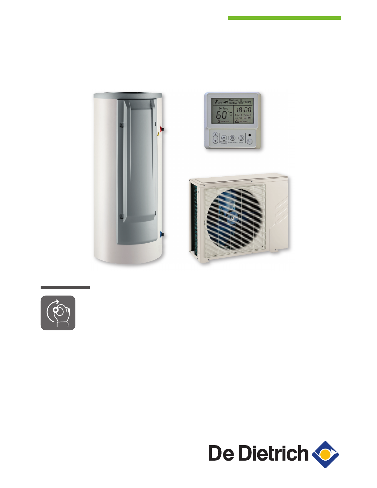
Thermodynamic water heater
KALIKO SPLIT
TWH Split FS 200 E
TWH Split FS 270 E
Serv. ref. SODU 2 M R1
Page 2

Dear Customer,
Thank you very much for buying this appliance.
Please read through the manual carefully before using the product, and keep it in a safe place for later reference. In order to
ensure continued safe and efficient operation we recommend that the product is serviced regularly. Our service and customer
service organisation can assist with this.
We hope you enjoy years of problem-free operation with the product.
Page 3

Contents
1 Safety . . . . . . . . . . . . . . . . . . . . . . . . . . . . . . . . . . . . . . . . . . . . . . . . . . . . . . . . . . . . . . . . . . . . . . . . . . . . . . . . . . . . . . . . . . . . 5
1.1 General safety instructions . . . . . . . . . . . . . . . . . . . . . . . . . . . . . . . . . . . . . . . . . . . . . . . . . . . . . . . . . . . . . . . . . . . . . . . 5
1.2 Recommendations . . . . . . . . . . . . . . . . . . . . . . . . . . . . . . . . . . . . . . . . . . . . . . . . . . . . . . . . . . . . . . . . . . . . . . . . . . . . . 6
1.3 Specific safety instructions . . . . . . . . . . . . . . . . . . . . . . . . . . . . . . . . . . . . . . . . . . . . . . . . . . . . . . . . . . . . . . . . . . . . . . . 9
1.4 Liabilities . . . . . . . . . . . . . . . . . . . . . . . . . . . . . . . . . . . . . . . . . . . . . . . . . . . . . . . . . . . . . . . . . . . . . . . . . . . . . . . . . . . . . 9
1.4.1 User's liability . . . . . . . . . . . . . . . . . . . . . . . . . . . . . . . . . . . . . . . . . . . . . . . . . . . . . . . . . . . . . . . . . . . . . . . . . .9
1.4.2 Installer's liability . . . . . . . . . . . . . . . . . . . . . . . . . . . . . . . . . . . . . . . . . . . . . . . . . . . . . . . . . . . . . . . . . . . . . . 10
1.4.3 Manufacturer's liability . . . . . . . . . . . . . . . . . . . . . . . . . . . . . . . . . . . . . . . . . . . . . . . . . . . . . . . . . . . . . . . . . . 10
1.5 Safety data sheet: refrigerant fluid R-134a . . . . . . . . . . . . . . . . . . . . . . . . . . . . . . . . . . . . . . . . . . . . . . . . . . . . . . . . . . 10
1.5.1 Product identification . . . . . . . . . . . . . . . . . . . . . . . . . . . . . . . . . . . . . . . . . . . . . . . . . . . . . . . . . . . . . . . . . . . 10
1.5.2 Hazard identification . . . . . . . . . . . . . . . . . . . . . . . . . . . . . . . . . . . . . . . . . . . . . . . . . . . . . . . . . . . . . . . . . . . 10
1.5.3 Composition of/Information on the ingredients . . . . . . . . . . . . . . . . . . . . . . . . . . . . . . . . . . . . . . . . . . . . . . . 11
1.5.4 First aid . . . . . . . . . . . . . . . . . . . . . . . . . . . . . . . . . . . . . . . . . . . . . . . . . . . . . . . . . . . . . . . . . . . . . . . . . . . . . 11
1.5.5 Fire prevention measures . . . . . . . . . . . . . . . . . . . . . . . . . . . . . . . . . . . . . . . . . . . . . . . . . . . . . . . . . . . . . . . 11
1.5.6 In the event of accidental spillage . . . . . . . . . . . . . . . . . . . . . . . . . . . . . . . . . . . . . . . . . . . . . . . . . . . . . . . . . 12
1.5.7 Handling . . . . . . . . . . . . . . . . . . . . . . . . . . . . . . . . . . . . . . . . . . . . . . . . . . . . . . . . . . . . . . . . . . . . . . . . . . . . .12
1.5.8 Personal protection . . . . . . . . . . . . . . . . . . . . . . . . . . . . . . . . . . . . . . . . . . . . . . . . . . . . . . . . . . . . . . . . . . . . 12
1.5.9 Regulations . . . . . . . . . . . . . . . . . . . . . . . . . . . . . . . . . . . . . . . . . . . . . . . . . . . . . . . . . . . . . . . . . . . . . . . . . . 13
2 About this manual . . . . . . . . . . . . . . . . . . . . . . . . . . . . . . . . . . . . . . . . . . . . . . . . . . . . . . . . . . . . . . . . . . . . . . . . . . . . . . . . . . 14
2.1 Website . . . . . . . . . . . . . . . . . . . . . . . . . . . . . . . . . . . . . . . . . . . . . . . . . . . . . . . . . . . . . . . . . . . . . . . . . . . . . . . . . . . . . 14
2.2 General . . . . . . . . . . . . . . . . . . . . . . . . . . . . . . . . . . . . . . . . . . . . . . . . . . . . . . . . . . . . . . . . . . . . . . . . . . . . . . . . . . . . . 14
2.3 Symbols used . . . . . . . . . . . . . . . . . . . . . . . . . . . . . . . . . . . . . . . . . . . . . . . . . . . . . . . . . . . . . . . . . . . . . . . . . . . . . . . . 14
2.3.1 Symbols used in the manual . . . . . . . . . . . . . . . . . . . . . . . . . . . . . . . . . . . . . . . . . . . . . . . . . . . . . . . . . . . . . 14
2.3.2 Symbols used on the appliance . . . . . . . . . . . . . . . . . . . . . . . . . . . . . . . . . . . . . . . . . . . . . . . . . . . . . . . . . . .14
3 Technical specifications . . . . . . . . . . . . . . . . . . . . . . . . . . . . . . . . . . . . . . . . . . . . . . . . . . . . . . . . . . . . . . . . . . . . . . . . . . . . . 15
3.1 Homologations . . . . . . . . . . . . . . . . . . . . . . . . . . . . . . . . . . . . . . . . . . . . . . . . . . . . . . . . . . . . . . . . . . . . . . . . . . . . . . . 15
3.1.1 Certifications . . . . . . . . . . . . . . . . . . . . . . . . . . . . . . . . . . . . . . . . . . . . . . . . . . . . . . . . . . . . . . . . . . . . . . . . . 15
3.1.2 2014/68/UE Directive . . . . . . . . . . . . . . . . . . . . . . . . . . . . . . . . . . . . . . . . . . . . . . . . . . . . . . . . . . . . . . . . . . .15
3.1.3 Ecodesign Directive . . . . . . . . . . . . . . . . . . . . . . . . . . . . . . . . . . . . . . . . . . . . . . . . . . . . . . . . . . . . . . . . . . . 15
3.1.4 Factory test . . . . . . . . . . . . . . . . . . . . . . . . . . . . . . . . . . . . . . . . . . . . . . . . . . . . . . . . . . . . . . . . . . . . . . . . . . 15
3.2 Technical data . . . . . . . . . . . . . . . . . . . . . . . . . . . . . . . . . . . . . . . . . . . . . . . . . . . . . . . . . . . . . . . . . . . . . . . . . . . . . . . .15
3.2.1 Technical data - Heat pump water heaters . . . . . . . . . . . . . . . . . . . . . . . . . . . . . . . . . . . . . . . . . . . . . . . . . . 15
4 Description of the product . . . . . . . . . . . . . . . . . . . . . . . . . . . . . . . . . . . . . . . . . . . . . . . . . . . . . . . . . . . . . . . . . . . . . . . . . . . . 17
4.1 General description . . . . . . . . . . . . . . . . . . . . . . . . . . . . . . . . . . . . . . . . . . . . . . . . . . . . . . . . . . . . . . . . . . . . . . . . . . . .17
4.2 Operating principle . . . . . . . . . . . . . . . . . . . . . . . . . . . . . . . . . . . . . . . . . . . . . . . . . . . . . . . . . . . . . . . . . . . . . . . . . . . . 17
4.2.1 Thermodynamic water heater . . . . . . . . . . . . . . . . . . . . . . . . . . . . . . . . . . . . . . . . . . . . . . . . . . . . . . . . . . . . 17
4.2.2 Operating principle for the thermodynamic water heater with outdoor unit . . . . . . . . . . . . . . . . . . . . . . . . . . 18
4.2.3 Operation of various MODES . . . . . . . . . . . . . . . . . . . . . . . . . . . . . . . . . . . . . . . . . . . . . . . . . . . . . . . . . . . . 18
4.2.4 Limit temperatures of the thermodynamic water heater . . . . . . . . . . . . . . . . . . . . . . . . . . . . . . . . . . . . . . . . 20
4.3 Main components . . . . . . . . . . . . . . . . . . . . . . . . . . . . . . . . . . . . . . . . . . . . . . . . . . . . . . . . . . . . . . . . . . . . . . . . . . . . . 21
4.3.1 Domestic hot water tank . . . . . . . . . . . . . . . . . . . . . . . . . . . . . . . . . . . . . . . . . . . . . . . . . . . . . . . . . . . . . . . . 21
4.3.2 Outdoor unit . . . . . . . . . . . . . . . . . . . . . . . . . . . . . . . . . . . . . . . . . . . . . . . . . . . . . . . . . . . . . . . . . . . . . . . . . .22
4.4 Control panel description . . . . . . . . . . . . . . . . . . . . . . . . . . . . . . . . . . . . . . . . . . . . . . . . . . . . . . . . . . . . . . . . . . . . . . . 23
4.4.1 Description of the control panel keys . . . . . . . . . . . . . . . . . . . . . . . . . . . . . . . . . . . . . . . . . . . . . . . . . . . . . . .23
4.4.2 Description of the control panel display . . . . . . . . . . . . . . . . . . . . . . . . . . . . . . . . . . . . . . . . . . . . . . . . . . . . .23
5 Operation . . . . . . . . . . . . . . . . . . . . . . . . . . . . . . . . . . . . . . . . . . . . . . . . . . . . . . . . . . . . . . . . . . . . . . . . . . . . . . . . . . . . . . . . .24
5.1 Initial commissioning . . . . . . . . . . . . . . . . . . . . . . . . . . . . . . . . . . . . . . . . . . . . . . . . . . . . . . . . . . . . . . . . . . . . . . . . . . .24
5.2 Installation shutdown . . . . . . . . . . . . . . . . . . . . . . . . . . . . . . . . . . . . . . . . . . . . . . . . . . . . . . . . . . . . . . . . . . . . . . . . . . 24
5.3 Frost Protection . . . . . . . . . . . . . . . . . . . . . . . . . . . . . . . . . . . . . . . . . . . . . . . . . . . . . . . . . . . . . . . . . . . . . . . . . . . . . . .24
6 Settings . . . . . . . . . . . . . . . . . . . . . . . . . . . . . . . . . . . . . . . . . . . . . . . . . . . . . . . . . . . . . . . . . . . . . . . . . . . . . . . . . . . . . . . . . . 25
6.1 List of parameters . . . . . . . . . . . . . . . . . . . . . . . . . . . . . . . . . . . . . . . . . . . . . . . . . . . . . . . . . . . . . . . . . . . . . . . . . . . . . 25
6.2 Setting the parameters . . . . . . . . . . . . . . . . . . . . . . . . . . . . . . . . . . . . . . . . . . . . . . . . . . . . . . . . . . . . . . . . . . . . . . . . . 25
6.2.1 Selecting the operating mode . . . . . . . . . . . . . . . . . . . . . . . . . . . . . . . . . . . . . . . . . . . . . . . . . . . . . . . . . . . . 25
6.2.2 Setting the time . . . . . . . . . . . . . . . . . . . . . . . . . . . . . . . . . . . . . . . . . . . . . . . . . . . . . . . . . . . . . . . . . . . . . . . 26
6.2.3 Programming the operating ranges . . . . . . . . . . . . . . . . . . . . . . . . . . . . . . . . . . . . . . . . . . . . . . . . . . . . . . . . 26
6.2.4 Setting the domestic hot water temperature setpoint . . . . . . . . . . . . . . . . . . . . . . . . . . . . . . . . . . . . . . . . . . 26
6.2.5 Activate forced electrical back-up . . . . . . . . . . . . . . . . . . . . . . . . . . . . . . . . . . . . . . . . . . . . . . . . . . . . . . . . . 27
6.3 Displaying the measured values . . . . . . . . . . . . . . . . . . . . . . . . . . . . . . . . . . . . . . . . . . . . . . . . . . . . . . . . . . . . . . . . . . 27
Contents
7679542 - v03 - 29102018 TWH Split FS 3
Page 4

7 Maintenance . . . . . . . . . . . . . . . . . . . . . . . . . . . . . . . . . . . . . . . . . . . . . . . . . . . . . . . . . . . . . . . . . . . . . . . . . . . . . . . . . . . . . . 29
7.1 Maintenance . . . . . . . . . . . . . . . . . . . . . . . . . . . . . . . . . . . . . . . . . . . . . . . . . . . . . . . . . . . . . . . . . . . . . . . . . . . . . . . . . 29
8 Troubleshooting . . . . . . . . . . . . . . . . . . . . . . . . . . . . . . . . . . . . . . . . . . . . . . . . . . . . . . . . . . . . . . . . . . . . . . . . . . . . . . . . . . . .30
8.1 Resolving error codes . . . . . . . . . . . . . . . . . . . . . . . . . . . . . . . . . . . . . . . . . . . . . . . . . . . . . . . . . . . . . . . . . . . . . . . . . . 30
8.1.1 List of error codes . . . . . . . . . . . . . . . . . . . . . . . . . . . . . . . . . . . . . . . . . . . . . . . . . . . . . . . . . . . . . . . . . . . . . 30
8.2 Checks after a disconnection of the mains supply . . . . . . . . . . . . . . . . . . . . . . . . . . . . . . . . . . . . . . . . . . . . . . . . . . . . 30
9 Disposal/recycling . . . . . . . . . . . . . . . . . . . . . . . . . . . . . . . . . . . . . . . . . . . . . . . . . . . . . . . . . . . . . . . . . . . . . . . . . . . . . . . . . . 31
9.1 General . . . . . . . . . . . . . . . . . . . . . . . . . . . . . . . . . . . . . . . . . . . . . . . . . . . . . . . . . . . . . . . . . . . . . . . . . . . . . . . . . . . . . 31
10 Appendix . . . . . . . . . . . . . . . . . . . . . . . . . . . . . . . . . . . . . . . . . . . . . . . . . . . . . . . . . . . . . . . . . . . . . . . . . . . . . . . . . . . . . . . . . 32
10.1 EC Declaration of Conformity . . . . . . . . . . . . . . . . . . . . . . . . . . . . . . . . . . . . . . . . . . . . . . . . . . . . . . . . . . . . . . . . . . . . 32
10.2 ErP information . . . . . . . . . . . . . . . . . . . . . . . . . . . . . . . . . . . . . . . . . . . . . . . . . . . . . . . . . . . . . . . . . . . . . . . . . . . . . . . 32
Contents
4 TWH Split FS 7679542 - v03 - 29102018
Page 5

1 Safety
1.1 General safety instructions
Danger
This appliance is not intended for use by persons
(including children) with reduced physical,
sensory or mental capabilities, or lack of
experience and knowledge, unless they have
been given supervision or instruction concerning
use of the appliance by a person responsible for
their safety. Children should be supervised to
ensure that they do not play with the appliance.
Caution
In the event of a refrigerant leakage:
1. Switch off the appliance.
2. Open the windows.
3. Do not use a naked flame, do not smoke, do
not operate electrical contacts or switches
(doorbell, light, motor, lift, etc.).
4. Avoid contact with the refrigerant. Danger of
frost injuries.
5. Evacuate the property.
6. Contact a qualified professional.
Danger of electric shock
Before any work, switch off the mains supply to
the thermodynamic water heater.
Important
Only qualified professionals are permitted to
install the thermodynamic water heater, in
accordance with prevailing local and national
regulations.
Warning
Do not touch the refrigeration connection pipes
with your bare hands while the heat pump is
running. Danger of burn or frost injury.
Caution
Take precautions with the domestic hot water.
Depending on the settings of the thermodynamic
water heater, the domestic hot water temperature
may exceed 65°C.
Caution
Only genuine spare parts may be used.
1 Safety
7679542 - v03 - 29102018 TWH Split FS 5
Page 6

Important
Only qualified professionals are authorised to
assemble, connect, commission and service the
installation.
1.2 Recommendations
Important
The thermodynamic water heater is intended to
be permanently connected to the domestic water
mains network.
Important
Respect the minimum and maximum water inlet
pressure to ensure correct operation of the
domestic hot water tank: refer to the chapter
Technical Specifications.
Caution
The pressure limiter device must be regularly
operated in order to remove limescale deposits
and ensure that it is not blocked.
A pressure reducer (not provided) is necessary
when the supply pressure exceeds 80% of the
calibration of the safety valve which must be
located upstream of the appliance.
As water may flow out of the discharge pipe on
the pressure limiter device, this latter must be
kept clear and open to the air.
Connect the pressure limiter device to a drain
pipe, kept open to the air, in a frost-free
environment, and at a continuous downward
gradient.
Caution
Draining the domestic hot water tank:
1. Shut off the domestic cold water inlet.
2. Open a hot water tap in the installation.
3. Open a valve on the safety unit.
4. When the water stops flowing, the domestic
hot water tank has been drained.
Caution
Install the thermodynamic water heater in a frostfree environment.
1 Safety
6 TWH Split FS 7679542 - v03 - 29102018
Page 7
Caution
Do not neglect to service the thermodynamic
water heater. Contact a qualified professional or
take out a maintenance contract for the obligatory
annual servicing of the thermodynamic water
heater.
Failure to service the appliance voids the
warranty.
Caution
Have the domestic hot water tank and heating
system drained by a qualified professional if the
home is left empty for a long period of time and
there is a chance of frost.
Important
Keep the domestic hot water tank and the
outdoor unit accessible at all times.
Important
Never remove or cover labels and data plates
affixed to the thermodynamic water heater.
Labels and data plates must be legible
throughout the entire lifetime of the
thermodynamic water heater. Immediately
replace damaged or illegible instructions and
warning labels.
Caution
Remove the thermodynamic water heater casing
only to perform maintenance and repair work.
Always put the casing back in place after such
work.
Important
Keep this document close to the place where the
appliance is installed.
Caution
To benefit from extended warranty cover, no
modifications must be made to the appliance.
Warning
In accordance with the NFC 15.100 electrical
safety standard, only qualified professionals are
permitted access to the inside of the appliance.
1 Safety
7679542 - v03 - 29102018 TWH Split FS 7
Page 8
Caution
The electric part of the domestic hot water tank
must always be connected to the protective
earthing.
Earthing must comply with the prevailing
installation standards.
Earth the appliance before making any electrical
connections.
For the type and calibre of the protective
equipment, refer to the chapter Electrical
Connections in the Installation and Service
Manual.
Caution
Install the outdoor unit on a solid, stable structure
capable of bearing its weight.
Caution
Do not install the thermodynamic water heater in
a place that has an atmosphere with a high salt
content.
Caution
Do not install the thermodynamic water heater in
a place exposed to steam or combustion gases.
Warning
Do not bring the heating water and the domestic
water into contact with each other in the the
heating system.
1 Safety
8 TWH Split FS 7679542 - v03 - 29102018
Page 9

1.3 Specific safety instructions
Warning
Refrigerant fluid and pipes:
Only use R-134a refrigerant fluid to fill the
system.
Use tools and pipe components especially
designed for use with
R-134a refrigerant fluid.
Use copper pipes deoxidised with phosphorus
to carry the refrigerant fluid.
Use beading to guarantee the tightness of the
connections.
Store the refrigerant connection pipes away
from dust and humidity (risk of damage to the
compressor).
Cover both ends of the pipes until the beading
process.
Do not use a load cylinder.
Regarding information on installation on the
appliance, electrical connection and connection
of the water circuit, refer to the paragraphs
below in this manual.
Regarding information on handling, servicing
and scrapping the appliance, refer to the
paragraphs below in this manual.
Caution
In order to limit the risk of being scalded, the
installation of a thermostatic mixing valve on the
domestic hot water flow pipes is recommended.
1.4
Liabilities
1.4.1
User's liability
To guarantee optimum operation of the system, you
must abide by the following instructions:
Read and follow the instructions given in the manuals
provided with the appliance.
Call on a qualified professional to carry out installation
and initial commissioning.
Get your installer to explain your installation to you.
Have the required inspections and maintenance
carried out by a qualified installer.
Keep the instruction manuals in good condition close
to the appliance.
1 Safety
7679542 - v03 - 29102018 TWH Split FS 9
Page 10

1.4.2
Installer's liability
The installer is responsible for the installation and initial
commissioning of the appliance. The installer must
observe the following instructions:
Read and follow the instructions given in the manuals
provided with the appliance.
Install the appliance in compliance with prevailing
legislation and standards.
Carry out initial commissioning and any checks
necessary.
Explain the installation to the user.
If maintenance is necessary, warn the user of the
obligation to check the appliance and keep it in good
working order.
Give all the instruction manuals to the user.
1.4.3
Manufacturer's liability
Our products are manufactured in compliance with the
requirements of the various Directives applicable. They
are therefore delivered with the
marking and any
documents necessary. In the interests of the quality of
our products, we strive constantly to improve them. We
therefore reserve the right to modify the specifications
given in this document.
Our liability as manufacturer may not be invoked in the
following cases:
Failure to abide by the instructions on installing and
maintaining the appliance.
Failure to abide by the instructions on using the
appliance.
Faulty or insufficient maintenance of the appliance.
1.5 Safety data sheet: refrigerant fluid R-134a
1.5.1
Product identification
Name of the refrigerant fluid: R–134a.
1.5.2
Hazard identification
Effects harmful to health:
The vapours are heavier than air and may lead to
asphyxia owing to reduced oxygen levels.
Liquefied gas: contact with the liquid may cause
serious frost burn and eye injuries.
Product classification:
1 Safety
10 TWH Split FS 7679542 - v03 - 29102018
Page 11

This product is not classified as a "hazardous
preparation" according to European Union regulations.
1.5.3 Composition of/Information on the
ingredients
Chemical nature:
1,1,1,2 - Tetrafluoroethane R-134a.
Ingredients that may lead to hazardous situations:
Tab.1 Fluid ingredients R-134a
Substance name Concentra
tion
Number CAS Number CE Classification PRP
1,1,1,2 - Tetra
fluoroethane
R-134a
100% 811-97-2 212-377-0 1430
1.5.4
First aid
If inhaled:
Evacuate the subject from the contaminated area and
take him into the open air.
If feeling unwell: call a doctor.
In the event of contact with the skin:
Treat frost injuries like burns. Rinse with copious
amounts of tepid water, do not remove clothing (risk of
adhesion to the skin).
If skin burns appear, call a doctor immediately.
In the event of contact with the eyes:
Rinse immediately in water, holding the eyelids well
apart (at least 15 minutes).
Consult an ophthalmologist immediately.
1.5.5
Fire prevention measures
Appropriate extinguishing agents:
All extinguishing agents can be used.
Inappropriate extinguishing agents:
None to our knowledge. In the event of fire nearby,
use the appropriate extinguishing agents.
Specific hazards:
Pressure elevation: in the presence of air, an
inflammable mixture may form under certain
temperature and pressure conditions.
Effect of heat: release of toxic and corrosive vapours.
1 Safety
7679542 - v03 - 29102018 TWH Split FS 11
Page 12

Special intervention methods:
Cool the volumes exposed to heat with water spray.
Protection of the firemen:
Full self-contained breathing apparatus.
Complete body protection.
1.5.6 In the event of accidental spillage
Individual precautions:
Avoid contact with the skin and eyes.
Do not intervene without appropriate protective
equipment.
Do not inhale the vapours.
Evacuate the hazardous area.
Stop the leakage.
Eradicate all sources of ignition.
Ventilate the spillage area mechanically (risk of
asphyxia).
Cleaning / Decontamination:
Allow residual product to evaporate.
1.5.7 Handling
Technical measures:
Ventilation.
Precautions to be taken:
No smoking.
Prevent the build-up of electrostatic charges.
Work in a well ventilated place.
1.5.8 Personal protection
Respiratory protection:
If ventilation is insufficient: AX type cartridge mask.
In confined spaces: self-contained breathing
apparatus.
Hand protection:
Protective gloves in leather or nitrile rubber.
Eye protection:
Safety glasses with side protection.
Skin protection:
Clothing made mostly of cotton.
Industrial hygiene:
Do not drink, eat or smoke in the work place.
1 Safety
12 TWH Split FS 7679542 - v03 - 29102018
Page 13

1.5.9
Regulations
Regulation (EU) No. 517/2014 of the European
Parliament and of the Council of 16 April 2014 on
fluorinated greenhouse gases and repealing
Regulation (EC) No. 842/2006.
Classified installations No. 1185.
1 Safety
7679542 - v03 - 29102018 TWH Split FS 13
Page 14

2 About this manual
2.1 Website
The user manual can also be found on our website.
2.2 General
This manual is intended for the end user of a TWH Split FS 200 E or TWH
Split FS 270 E thermodynamic water heater comprising a SFS 200 E or
SFS 270 E domestic hot water tank and an SODU 2 M outdoor unit with
display.
2.3
Symbols used
2.3.1 Symbols used in the manual
This manual uses various danger levels to draw attention to special
instructions. We do this to improve user safety, to prevent problems and to
guarantee correct operation of the appliance.
Danger
Risk of dangerous situations that may result in serious personal
injury.
Danger of electric shock
Risk of electric shock.
Warning
Risk of dangerous situations that may result in minor personal
injury.
Caution
Risk of material damage.
Important
Please note: important information.
See
Reference to other manuals or pages in this manual.
2.3.2 Symbols used on the appliance
1 Alternating current
2 Protective earthing
3 Before installing and commissioning the appliance, carefully read
the instruction manuals provided.
4 Dispose of used products through an appropriate recovery and
recycling structure.
5 Caution: danger of electric shock, live parts. Disconnect the mains
power prior to carrying out any work.
6 Electrical back-up
7 CE Marking: equipment conforming to European legislation
8 NF Marking: equipment that respects French safety and
performance criteria
9 Protection rating.
Fig.1 Symbols used on the appliance
MW-4000099-1
1
2
3
4
5
6
7
8
9
IPX1B
2 About this manual
14 TWH Split FS 7679542 - v03 - 29102018
Page 15

3 Technical specifications
3.1 Homologations
3.1.1 Certifications
NF certification
Specifications LCIE 103–15/B (July 2011) for NF Electricity Performance
Marking
This product complies with the requirements of the following NF
Electricity Standards:
EN 60335-1:2012 + A11:2014
EN 60335-2-21:2003 + A1:2005 + A2:2008
EN 60335-2-40:2003 + A11:2004 + A12:2005 + A1:2006 + A2:2009 +
A13:2012
EN 62233:2008
EN 16147:2011
EN 55014-1:2006+A1:2009+A2:2011
EN 55014-2:2015
EN 61000-3-2:2014
EN 61000-3-3:2013
Electrical Conformity / CE Marking
This product complies with the requirements of the following European
Directives and Standards:
Low Voltage Directive 2014/35/EU
Generic standard: EN 60335-1
Relevant standards: EN 60335-2-21, EN 60335-2-40
Electromagnetic Compatibility Directive 2014/30/EU
Generic standards: EN 61000-6-3, EN 61000-6-1
Relevant Standard: EN 55014
3.1.2 2014/68/UE Directive
This product conforms to the requirements of European Directive
2014/68/UE, article 4, paragraph 3, on pressure equipment.
3.1.3 Ecodesign Directive
This product conforms to the requirements of European Directive
2009/125/EC on the ecodesign of energy-related products.
3.1.4 Factory test
Before leaving the factory, each appliance is tested for the following:
Water tightness
Air tightness
Electrical tests (components, safety).
3.2
Technical data
3.2.1
Technical data - Heat pump water heaters
Tab.2 Technical parameters for heat pump water heaters
Parameters Unit TWH Split FS 200 E TWH Split FS 270 E
Daily electricity consumption (
Q
elec
) kWh 3.578 5.617
Declared load profile - L XL
Sound pressure level at 1 m indoors (
L
WA
)
(1)
dB(A) 17 17
3 Technical specifications
7679542 - v03 - 29102018 TWH Split FS 15
Page 16

Parameters Unit TWH Split FS 200 E TWH Split FS 270 E
Daily fuel consumption (
Q
fuel
) kWh
Emissions of nitrogen oxides (
NO
X
) mg/kWh
Weekly fuel consumption with smart controls (
Qfuel,
week,smart
) kWh - -
Weekly electricity consumption with smart controls (
Q
elec
,
week,smart
)
kWh - -
Weekly fuel consumption without smart controls (
Q
fuel, week,smart
) kWh - -
Weekly electricity consumption without smart controls (
Q
elec
,
week,smart
)
kWh - -
Storage volume (V) l 215.0 270.0
Mixed water at 40°C (V40)
(2)
l 300 373
Sound power level (LWA) outdoors
(1)
dB(A) 57 57
Output (outdoor unit) with air temperature = 7°C W 1750 1750
Absorbed electrical power (outdoor unit) W 900 900
Heating time (10-54°C)
(3)
hours 5.5 7.1
COP in accordance with the EN16147 standard
(3)
- 3.30 3.42
Pes (Power)
(3)(4)
W 26.5 28.5
Air flow rate - maximum
m3/h
1300 1300
Immersion heater output W 2400 2400
Operating pressure MPa (bar) 1.0 (10) 1.0 (10)
Power supply voltage V 230 230
Circuit breaker A 16 16
R134a refrigerant kg 1.60 1.60
R-134a refrigerant
(5)
tCO2e 2.28 2.28
Length of the refrigeration connection (minimum / maximum) m 2 / 20 2 / 20
Maximum difference in height on the refrigeration connection m 10 10
Weight of the domestic hot water tank (empty) kg 70 82
Protection of the domestic hot water tank IP X1B X1B
Weight of the outdoor unit kg 33 33
Protection of the outdoor unit IP 24 24
Limit operating temperatures of the outdoor unit °C -15 / 42 -15 / 42
Settings range for the domestic hot water set point °C 38 / 75 38 / 75
(1) Value obtained at average air temperature of 20°C when heating from 10°C to 55°C.
(2) The equivalent volume of hot water at 40 °C.
(3) Value obtained with an air temperature of 7°C and a cold water temperature of 10°C, according to LCIE Specifications No. 103-15/
B:2011 based on the NF EN 16147 standard, with a 5-m long refrigeration connection with 0 m difference in height.
(4) Electrical power consumed with no hot water use.
(5) Quantity of refrigerant calculated in tonnes of CO2 equivalent.
Important
The values in tonnes of CO2 equivalent are calculated using the
following formula: quantity (in kg) of refrigerant fluid x GWP/1000.
GWP = Global Warming Potential. The GWP of R-134a is 1430.
3 Technical specifications
16 TWH Split FS 7679542 - v03 - 29102018
Page 17

4 Description of the product
4.1 General description
The thermodynamic water heaters in the KALIKO SPLIT range have the
following specifications:
Floor-standing thermodynamic storage water heater,
Heat pump extracting energy from the outside air,
Control panel used to:
display the domestic hot water temperature,
adjust the timer program.
2.4 kW steatite immersion heater,
Glass-lined tank protected by magnesium anode,
Very thick insulation (0% CFCs).
The domestic hot water tank can be heated by:
The outdoor unit,
The immersion heater (up to 75°C).
4.2
Operating principle
4.2.1 Thermodynamic water heater
The thermodynamic water heater uses the outside air to produce domestic
hot water.
The refrigerant circuit is a closed circuit in which the R134a refrigerant
plays the role of an energy carrier.
The heat from the intake air is transferred to the refrigerant in the finned
heat exchanger at a low evaporation temperature.
The refrigerant is drawn in in vapour form by a compressor, which raises it
to a higher pressure and temperature and sends it to the condenser. In the
condenser, the heat extracted in the evaporator and some of the energy
absorbed by the compressor are released into the water.
The refrigerant is depressurised in the expansion valve and then cooled.
The refrigerant fluid can again extract the heat contained in the intake air
from the evaporator.
1
Domestic hot water tank
2
Outdoor unit
3
Condenser
4
Evaporator
5
Compressor
6
Expansion valve
7
Fan
8
Air flow
Fig.2 Schematic diagram
MW-4000108-1
1
6
7 4 5 3
8
2
4 Description of the product
7679542 - v03 - 29102018 TWH Split FS 17
Page 18

4.2.2 Operating principle for the thermodynamic water heater
with outdoor unit
Depending on the source of energy used to heat the water in the
thermodynamic water heater (heat pump only, immersion heater only, or
heat pump and immersion heater combined), the heating time for the
thermodynamic water heater varies according to the room temperature.
Only half the capacity of the domestic hot water tank is heated when the
energy source is immersion heater only.
X Room temperature (°C)
Y Heating time (hours)
1 Source of energy: heat pump and immersion heater combined
2 Source of energy: immersion heater
3 Source of energy: heat pump
X Room temperature (°C)
Y Heating time (hours)
1 Source of energy: heat pump and immersion heater combined
2 Source of energy: immersion heater
3 Source of energy: heat pump
4.2.3 Operation of various MODES
The main and default heat source for the thermodynamic water heater is
the heat pump.
If the room temperature is outside the heat pump's operating range, it will
cease the function. The water heater automatically activates the
immersion heater and the code bA is shown on the control panel display.
The room temperature range adapted for this operating mode is between
-15°C and +43°C.
For the 3 operating modes:
the thermodynamic water heater can heat the domestic hot water to a
maximum temperature of 65°C,
the domestic hot water temperature set point can be set to between 25
and 75°C.
Operation in AUTO MODE = AUTOMATIC MODE
The thermodynamic water heater can heat the water using the following
sources of energy:
the heat pump,
the immersion heater
or both systems simultaneously.
Fig.3 Model TWH Split FS 200 E
y
x
0
-20 -10 0 10 20 30 40 50
5
10
15
MW-1000861-1
1
2
3
Fig.4 Model TWH Split FS 270 E
y
x
1
2
3
0
-20 -10 0 10 20 30 40 50
5
10
15
18
MW-1000862-1
4 Description of the product
18 TWH Split FS 7679542 - v03 - 29102018
Page 19

Tab.3
T = Ambient temperature Source(s) of energy used
At least one of the following 3 con
ditions must be true:
T < –15 °C
Water temperature > variable
temperature set point according
to the outdoor temperature
T > +43 °C
Immersion heater
–15 °C < T < Td Heat pump and immersion heater
operate simultaneously if necessa
ry
The following 2 conditions must be
true:
T > Td
Water temperature < 65°C
Heat pump
Operation in HYBRID MODE = HYBRID MODE
Important
HYBRID MODE = HYBRID MODE: heat pump with compulsory
coupling to an instant boiler.
The thermodynamic water heater can heat the water using 2 sources of
energy: heat pump and instant boiler:
the heat pump is intended to preheat the domestic hot water,
the instant boiler is used to heat the domestic hot water to the required
temperature for use.
No electrical back-up for this mode.
Tab.4
T = Ambient temperature Source(s) of energy used
T < T4 Instant boiler
T4 < T < 43 °C
Water temperature < 65°C
Heat pump + instant boiler
Operation in OPT.BACKUP = OFF-PEAK RATE/PEAK RATE
OPTIMISATION MODE
The thermodynamic water heater can only heat the water during:
the programmed timer range,
or when the off-peak rate signal is present.
The thermodynamic water heater can heat the water using the heat pump
or the immersion heater:
the heat pump operates as the priority source,
the immersion heater starts when the heat pump is operating, to enable
the required temperature set point to be reached before the end of the
period.
4 Description of the product
7679542 - v03 - 29102018 TWH Split FS 19
Page 20

Tab.5
T = Ambient temperature Source(s) of energy used
T < –15 °C
Water temperature > variable
temperature set point according
to the outdoor temperature
T > +43 °C
Immersion heater
-15°C < T < 43°C Heat pump and immersion heater
operate simultaneously if necessa
ry
4.2.4 Limit temperatures of the thermodynamic water heater
X
Air temperature (°C)
Y
Domestic hot water temperature (°C)
The graph opposite shows the maximum temperature at which the outdoor
unit can heat up the water in the domestic hot water tank according to air
temperature.
To preserve the components and maintain an optimal service life of the
thermodynamic water heater, the outdoor unit works at temperatures of
between -15°C and +42 °C. Outside of this temperature range, the surplus
heating of the domestic hot water is provided by the immersion heater.
Fig.5
MW-4000102-3
40
35
-15 -10
-7
2 32 4337
X
58
55
60
62
65
Y
-2
4 Description of the product
20 TWH Split FS 7679542 - v03 - 29102018
Page 21

4.3 Main components
4.3.1 Domestic hot water tank
1
Top cover
2
Top insulation
3
Sensor cable duct
4
230-V sensor cable duct
5
Condenser tube
6
Domestic hot water outlet
7
Magnesium anode
8
Sensor tube
9
Temperature sensor
10
Steatite immersion heater
11
Safety thermostat
12
Condenser
13 Domestic cold water inlet
14 1/4” refrigeration connection
15 Sensor cable clamp
16 3/8” refrigeration connection
17 230-V cable clamp
Important
Do not place anything on top of the domestic hot water tank.
Fig.6 Main components
5
8
9
11
13
10
12
7
MW-4000109-2
1
2
3
4
14
6
15
16
17
4 Description of the product
7679542 - v03 - 29102018 TWH Split FS 21
Page 22

4.3.2 Outdoor unit
Fig.7 Main components
4
3
2
1
12
15
13
14
16
17
11
8
9
10
7
MW-4000110-1
5 6
1
Evaporator
2
Fan
3
Compressor
4
Compressor outlet temperature sensor
5
Display connection terminal block
6
Temperature sensor connector
7
Three-way valve
8
2-way valve
9
Evaporator temperature sensor
10
Filter-drier
11
Outside temperature sensor
12
Electronic expansion valve
13
High pressure pressure switch
14
4-way valve
15
Electrical connection terminal block
16
Air suction temperature sensor
17
Electrical control unit
4 Description of the product
22 TWH Split FS 7679542 - v03 - 29102018
Page 23

4.4 Control panel description
4.4.1 Description of the control panel keys
1
Keys and :
Selection
Setting the values
2
On / off key for forced electrical back-up
3
Timer program access key
4
Confirm key
5
key:
Domestic hot water production
Holiday mode
6
Operating indicator light:
Indicator light on = Domestic hot water production active
Indicator light off = Holiday mode
4.4.2 Description of the control panel display
1 Hybrid mode operating
2 Heating temperature
Domestic hot water temperature
Error code detected
3 Error detected
4 Forced electrical back-up in operation
5 Compressor running
6 Time display
7 Timer program display
8 Off-peak rate optimisation mode in operation
Fig.8
MW-4000111-3
1
6
2
5
3 4
Electrical
Heating
Timer /
Clock
Enter
Opt ModeHybrid Mode
Fig.9
MW-4000112-3
Enter
Electrical
Heating
Timer /
Clock
Opt ModeHybrid Mode
2
3
4 5
6
7
8
1
4 Description of the product
7679542 - v03 - 29102018 TWH Split FS 23
Page 24

5 Operation
5.1 Initial commissioning
Initial commissioning must be performed by a qualified professional.
Commissioning of the thermodynamic water heater should be carried out:
When it is used for the first time;
After a prolonged shut-down;
After any event that may require complete re-installation.
Commissioning of the thermodynamic water heater allows the user to
review the various settings and checks to be made to start up the water
heater in complete safety.
1. Switch on the installation.
Indicator light on Domestic hot water production active
Indicator light off Domestic hot water production inactive.
Frost protection function active.
Outside of off-peak rate.
The thermodynamic water heater is in Holiday
Mode.
2. Switch on the control panel by pressing the key:
The compressor starts up after 3 minutes if domestic hot water
production is required.
If an error code appears on the control panel, refer to the list of error
codes.
5.2 Installation shutdown
Important
To prevent deletion of the control settings, avoid switching off the
domestic hot water tank.
1. Press the MODE button on the display.
2. Deactivate the operating ranges to place the domestic hot water tank
in
Holiday mode.
The thermodynamic water heater is thus protected against frost.
5.3 Frost Protection
In the event of prolonged absence:
1. Press the button on the control panel.
2. Deactivate the operating ranges to place the domestic hot water tank
in
Holiday mode.
The appliance is thus protected against frost.
Fig.10
MW-4000163-3
Electrical
Heating
Enter
Timer /
Clock
Opt ModeHybrid Mode
5 Operation
24 TWH Split FS 7679542 - v03 - 29102018
Page 25

6 Settings
6.1 List of parameters
Tab.6 Operating modes
Digit Associated Mode
AUTO MODE = AUTOMATIC MODE
HYBRID MODE = HYBRID MODE
OPT.BACKUP = PEAK RATE/OFF-PEAK RATE OPTIMISATION MODE
RESET METERS
COOLING MODE
Tab.7 Adjustable parameters
Parameter Description Factory setting
Hysteresis for starting heating.
Can be set from 3 to 20°C.
5°C
Room temperature limit authorised for operation of the heat
pump, in Hybrid Mode.
Can be set from -14 to 20°C.
5°C
Room temperature operating limit for the electrical back-up.
Can be set from -5 to 18°C
3°C
Main timer range duration at Off-peak rate if wired, in Optimi
sation Mode.
8 hours
6.2 Setting the parameters
6.2.1 Selecting the operating mode
1. Access the list of available operating modes by simultaneously
pressing the and keys.
2. Select the desired mode by pressing the or key.
Digit Operating
mode
Description Adjustment required
Automatic
mode
Domestic hot water is heated according to the cli
mate conditions:
by the heat pump, and/or
by the immersion heater.
/
Hybrid mode Domestic hot water is:
first pre-heated using the heat pump,
then heated by the instant boiler.
THmin setting: heat pump minimum operating tem
perature.
Optimisation
Mode
Domestic hot water is heated for pre-determined
periods:
by the timer programming,
by the off-peak rate signal.
Domestic hot water is heated by the heat pump
and by the immersion heater to reach the set point
temperature before the end of the off-peak rate.
H1 setting: duration (in hours) of the longest offpeak time range.
Consumption
mode
Read the different consumption values
Cooling
mode
The refrigerant can be recovered.
Immersion
heater power
6 Settings
7679542 - v03 - 29102018 TWH Split FS 25
Page 26

3. Confirm the selection by pressing the key.
6.2.2 Setting the time
1. Press the key to set the time.
The hours start flashing.
2. Set the hours and minutes by pressing the or keys.
3. Confirm the hours and minutes by pressing the key.
6.2.3 Programming the operating ranges
The operating ranges of the thermodynamic water heater define the
periods when the water heater is to produce domestic hot water.
Two operating ranges are available: Timer 1 and Timer 2, they are set in
the same way, one after the other.
1. Select Timer 1 - On by pressing three times on the key.
2. Set the hours and minutes of the start time of the operating range by
pressing the or key.
3. Confirm the start of the operating range by pressing the key.
4. Set the hours and minutes of the end time of the operating range by
pressing the
or key.
5. Confirm the end of the operating range by pressing the key.
6. Confirm the first operating range by pressing the key.
7. Select the second operating range by pressing the key, if
necessary.
8. Repeat steps 2 to 6 to set the second operating range.
9. Confirm the second operating range by pressing the key.
6.2.4
Setting the domestic hot water temperature setpoint
The domestic hot water setpoint is set with the and keys.
1. Press the key to increase the setpoint or press the key to
reduce it.
The setpoint value flashes.
2. Confirm by pressing the key.
Fig.11
MW-4000168-3
Opt ModeHybrid Mode
Fig.12
MW-4000172-4
Opt ModeHybrid Mode
Fig.13
MW-4000176-3
Opt ModeHybrid Mode
Fig.14
MW-4000177-3
Electrical
Heating
Timer /
Clock
Enter
Opt ModeHybrid Mode
6 Settings
26 TWH Split FS 7679542 - v03 - 29102018
Page 27

Domestic hot water setpoint according to the number of
showers per day
Tab.8 Domestic hot water setpoint
Number of showers
per day
DHW setpoint for TWH
Split FS 200 E
DHW setpoint for TWH
Split FS 270 E
3 50 °C 50 °C
4 50 °C 50 °C
5 50 °C 50 °C
6 55 °C 50 °C
7 60 °C 50 °C
8 65 °C 55 °C
9 70 °C 60 °C
10 - 65 °C
11 - 70 °C
6.2.5 Activate forced electrical back-up
The forced electrical back-up mode enables domestic hot water to be
provided more quickly thanks to the simultaneous operation of the heat
pump and electrical back-up.
1. Activate forced electrical back-up by pressing the key.
The Electrical Heating icon flashes.
When the set temperature of the hot water is reached, the control
panel returns to Automatic mode.
2. It is confirmed after a few seconds.
6.3
Displaying the measured values
The system constantly measures different data, such as the water
temperature or energy consumption. This data can be read on the control
panel.
1. Press the and keys simultaneously.
Fig.15
MW-4000178-4
Electrical
Heating
Timer /
Clock
Enter
Opt ModeHybrid Mode
6 Settings
7679542 - v03 - 29102018 TWH Split FS 27
Page 28

2. Scroll through the measured values with the or keys.
Tab.9
Code Description Factory setting / Unit
Water temperature °C
Outside air temperature
(1)
°C
Evaporation temperature °C
Hysteresis for starting heating.
Can be set from 3 to 20°C.
5°C
Electric power consumption A
Differential live/neutral current A
Total energy consumption for the thermodynamic water heater kWh
Energy consumption of the heat pump from midnight Wh
Energy consumption of the immersion heater from midnight Wh
Total runtime for the thermodynamic water heater hours
Total duration of compressor operation hours
Total runtime for the immersion heater hours
Operating mode:
= : thermodynamic water heater off
= : heat pump on
= : electrical back-up on
Fan speed:
: fan off
: low speed
: high speed
First error code
Second error code
Third error code
Software version
(1) Negative temperatures are displayed as follows: –10 °C is displayed as –A, –11°C is displayed as –B, etc...
6 Settings
28 TWH Split FS 7679542 - v03 - 29102018
Page 29

7 Maintenance
7.1 Maintenance
Caution
Installation and maintenance of the appliance must be carried out
by a certified professional in accordance with prevailing statutory
texts and codes of practice.
Important
When the appliance is switched off, the fan continues to run by
inertia for approximately one minute.
Maintenance operations are important for the following reasons:
To guarantee optimum performance.
To extend the life of the equipment.
To provide an installation which offers the customer optimum comfort
over time.
Caution
The control components must never come into contact with water.
Before cleaning, cut the power to the appliance.
Warning
If refrigeration connections have to be disconnected, the
refrigerant fluid should be collected.
MW-4000184-1
OFF
7 Maintenance
7679542 - v03 - 29102018 TWH Split FS 29
Page 30

8 Troubleshooting
8.1 Resolving error codes
If an error occurs, the control panel will display a key and a code The code
is important for the correct and rapid diagnosis of the type of malfunction
and for any technical assistance that may be needed.
1. Make a note of the code displayed.
2. Switch off the appliance.
3. Switch the appliance back on.
The appliance starts up again autonomously when the reason for
the disruption has been cleared.
4. If the error code is displayed again, correct the problem by following
the instructions in the table below.
8.1.1 List of error codes
If one of the following error codes is displayed, contact your authorised
maintenance technician.
Tab.10 Ex-type error codes
Code Description
Communication error between the outdoor unit and the control panel
Water temperature sensor T5L error
Evaporation temperature sensor T3 error
Air temperature sensor T4 error
Air suction temperature sensor Th error
Air discharge temperature sensor Tp error
Tab.11 Px type error codes
Code Description
High pressure error
Electrical overconsumption error on the compressor
Discharge temperature error: too high
Air temperature information outside the operating limits
Consumption error on the electrical back-up
The heat pump continues to operate but without electrical back-up
Error on the main controller
Frost protection running
8.2
Checks after a disconnection of the mains supply
1. Check that the thermodynamic water heater is running (green LED
on). Otherwise, press the MODE key.
2. Check the time setting on the control panel.
3. Check the programming of the operating ranges.
Fig.16
MW-4000188-3
Electrical
Heating
Enter
Timer /
Clock
Opt ModeHybrid Mode
8 Troubleshooting
30 TWH Split FS 7679542 - v03 - 29102018
Page 31

9 Disposal/recycling
9.1 General
Warning
This appliance bears the recycling symbol pursuant to European
Directive 2002/96/EC on Waste from Electrical and Electronic
Equipment (WEEE). In correctly disposing of this appliance, you
are helping to prevent any consequences harmful to the
environment or human health.
Important
The symbol found on this appliance and in the documentation that
accompanies it indicates that this product may under no
circumstances be treated as household waste. It must therefore
be brought to a waste collection centre responsible for recycling
electrical and electronic equipment.
As regards scrapping, abide by the standards on the elimination of waste
in force in the country of installation.
If electrical appliances are discarded on a rubbish tip, hazardous
substances may leak into the groundwater, enter the food chain and have
harmful consequences on health and well-being.
Fig.17 Recycling
MW-3000179-03
9 Disposal/recycling
7679542 - v03 - 29102018 TWH Split FS 31
Page 32

10 Appendix
10.1 EC Declaration of Conformity
The unit complies with the standard type described in the EC declaration
of conformity. It has been manufactured and commissioned in accordance
with European directives.
The original declaration of conformity is available from the manufacturer.
10.2 ErP information
Tab.12 Product fiche for heat pump water heaters
Brand name – Product name Unit TWH Split FS
200 E
TWH Split FS
270 E
Declared load profile - L XL
Water heating energy efficiency class under average climate conditions -
A+A
+
Water heating energy efficiency under average climate conditions % 136.00 140.00
Annual energy consumption
kWh
(1)
754 1199
Other load profiles for which the water heater is suitable to use and the
corresponding water heating energy efficiency and annual electricity con
sumption.
(2)
- - -
Thermostat temperature setting °C 55.00 54.00
Sound power level
L
WA
indoors
(2)
dB(A) 17 17
Ability to function during off-peak hours
(2)
- No No
Smart control enabled
(3)
- No No
Water heating energy efficiency, under colder - warmer climate conditions % 90.00 - 167.00 92.00 - 173.00
Annual energy consumption, under colder - warmer climate conditions
kWh
(1)
1141 - 612 1813 - 970
Sound power level
L
WA
outdoors dB(A) 57 57
(1) Electricity
(2) If applicable
(3) If the smart control settings value is "1", the water heating energy efficiency and annual electricity and fuel consumption information only
relates to enabled smart control settings.
See
For specific precautions about assembling, installing and
maintaining: See Safety Instructions
10 Appendix
32 TWH Split FS 7679542 - v03 - 29102018
Page 33

10 Appendix
7679542 - v03 - 29102018 TWH Split FS 33
Page 34

10 Appendix
34 TWH Split FS 7679542 - v03 - 29102018
Page 35

© Copyright
All technical and technological information contained in these technical instructions, as well as any drawings and technical
descriptions supplied, remain our property and shall not be multiplied without our prior consent in writing. Subject to alterations.
Page 36

DE DIETRICH
FRANCE
NEUBERG S.A.
LU
DE DIETRICH SERVICE
AT
DE DIETRICH
CN
www.dedietrich-thermique.fr
www.neuberg.lu
www.dedietrich-heating.com
www.dedietrich-heating.com
www.dedietrich-heiztechnik.com
SERVICE CONSOMMATEURS
0 825 120 520
0,15 €
/ min
03 88 80 27 00
03 88 80 27 99
+352 (0)2 401 401
0800 / 201608 freecall
+86 (0)106 581 4017
+86 (0)106 581 4018
+86 (0)106 581 7056
+86 (0)106 581 4019
contactBJ@dedietrich.com.cn
Direction de la Marque
57, rue de la Gare - F-67580 Mertzwiller
VAN MARCKE
BE
www.vanmarcke.be
+32 (0)56/23 75 11
Weggevoerdenlaan 5
B- 8500 KORTRIJK
39 rue Jacques Stas - B.P.12
L- 2549 LUXEMBOURG
Room 512, Tower A, Kelun Building
12A Guanghua Rd, Chaoyang District
C-100020 BEIJING
DE DIETRICH THERMIQUE
I
beria S.L.U
ES
www.dedietrich-calefaccion.es
+34 935 475 850
info@dedietrich-calefaccion.es
C/Salvador Espriu, 11
08908 L’HOSPITALET de LLOBREGAT
BDR THERMEA C
zech Republic s.r.o
CZ
DE DIETRICH
Technika Grzewcza sp. z o.o.
PL
www.dedietrich.cz
www.facebook.com/DeDietrichPL
www.dedietrich.pl
+420 271 001 627
dedietrich@bdrthermea.cz
+48 71 71 27 400
biuro@dedietrich.pl
MEIER TOBLER AG
CH
www.meiertobler.ch
+41 (0) 44 806 41 41
info@meiertobler.ch
Bahnstrasse 24 - CH - 8603 SCHWERZENBACH
Serviceline
+41 (0)8 00 846 846
MEIER TOBLER SA
CH
www.meiertobler.ch
+41 (0) 21 943 02 22
info@meiertobler.ch
Chemin de la Veyre-d'En- Haut B6,
CH -1806 St-Légier-La-Chiésaz
Jeseniova 2770/56 - 130 00 Praha 3
ul. Północna 15-19, 54-105 Wrocław
Serviceline
+41 (0)8 00 846 846
000 «БДP T Pyc»
RU
www.dedietrich.ru
8 800 333-17-18
info@dedietrich.ru
129164, Россия, г. Москва
Зубарев переулок, д. 15 /1
Бизнес-центр «Чайка Плаза»,офис 309
DUEDI S.r.
l
IT
www.duediclima.it
+39 0171 85717 0
+39 0171 687875
info@duediclima.it
Distributore Uffi ciale Esclusivo
De Dietrich-Thermique Italia Via Passatore, 12
12010 San Defendente di Cervasca CUNEO
801 080 881
Infocentrala
7679542 - v03 - 29102018
7679542-001-03
 Loading...