

DeDietrich Cor-Email Series, CES Series, CEB Series Installation And User Instruction Manual
Page 1

Notice d’installation et d’utilisation - Garantie
Installation and user’s instruction manual - Guarantee
Voor de installatie en het gebruik - Garantie
Un chauffe-eau De Dietrich parce que votre confort est précieux
n
n
chauffe-eau électriques
Cor-Email
n
chauffe-eau électrique CEB
n
chauffe-eau électrique CES
n
Cor-Email electric water
heater
n
CEB electric water heater
n
CES electric water heater
Cor-Email elektrische boilers
n
CEB elektrische boiler
n
CES elektrische boiler
Eau chaude à volonté
Page 2

REMERCIEMENTS / ACKNOWLEDGMENTS / DANK U
Vous venez de choisir un chauffe-eau de
notre gamme et nous vous remercions de
votre confiance.
Conçu et fabriqué dans un souci permanent de perfection, cet appareil vous apportera entière satisfaction pendant de longues
années.
Nous vous remercions de lire attentivement
cette notice avant d’installer ce chauffe-eau
et vous invitons à la conserver au même
titre que le bon de garantie figurant en dernière page. Notre responsabilité ne saurait
être engagée pour des dommages causés
par une mauvaise installation ou par le non
respect des instructions se trouvant dans ce
document. En particulier, nous vous rappelons que :
n l’installation doit être effectuée par un
personnel qualifié, dans le respect du DTU
- Plomberie 60-1 additif 4 (NFP 40-201
ou RGIE).
n le branchement électrique doit être confor-
me aux indications figurant au paragraphe correspondant, selon la norme NFC
15-100.
You have just selected one of our water heaters, and we would like to thank you for your
confidence.
This water heater was designed and manufactured with perfection in mind at all times,
and will serve you reliably for many years.
Please read these instructions carefully before
installing this electric water heater, and keep
the guarantee certificate on the last page
in a safe place. We cannot be responsible for
damage caused by poor installation or by
failure to respect the instructions given in this
document. In particular, remember that:
n the installation must be done by qualified
personnel in accordance with the DTU
(Unified Technical Document) entitled
Plumbing 60-1 addendum 4 (NFP 40-
201) or the plumbing regulation applied.
n electrical connections must be made in
accordance with the instructions given in
the appropriate section, according to NF
standard C 15-100.
n installation must be in accordance with the
current I.E.E. WIRING REGULATIONS.
U hebt zopas een boiler uit onze collectie
gekozen en wij danken u voor uw vertrouwen.
Qua ontwerp en fabricage streven wij
voortdurend naar een perfect resultaat; dit
toestel zal u dan ook jarenlang tevreden
stellen.
Wij verzoeken u deze handleiding aandachtig te lezen alvorens de boiler te
installeren en ze zorgvuldig op te bergen
samen met de garantiebon op de laatste
bladzijde. Wij kunnen in geen geval aansprakelijk worden gesteld voor schade die
te wijten is aan een verkeerde installatie of
aan het niet naleven van de instructies uit
dit document. Wij vestigen uw aandacht in
het bijzonder op de volgende punten:
n de installatie moet gebeuren door een
erkende installateur met inachtneming
van de norm DTU - Loodgieterij 60-1
bijvoegsel 4 (NFP 40 -201).
n bij de elektrische installatie dienen de
aanwijzingen uit de volgende paragraaf
(cf. norm NFC 15-100 en het ARGI)
te worden gevolgd.
2
Page 3
CARACTéRISTIqUES TEChNIqUES / TEChNICAL ChARACTERISTICS / TEChNISChE KENMERKEN
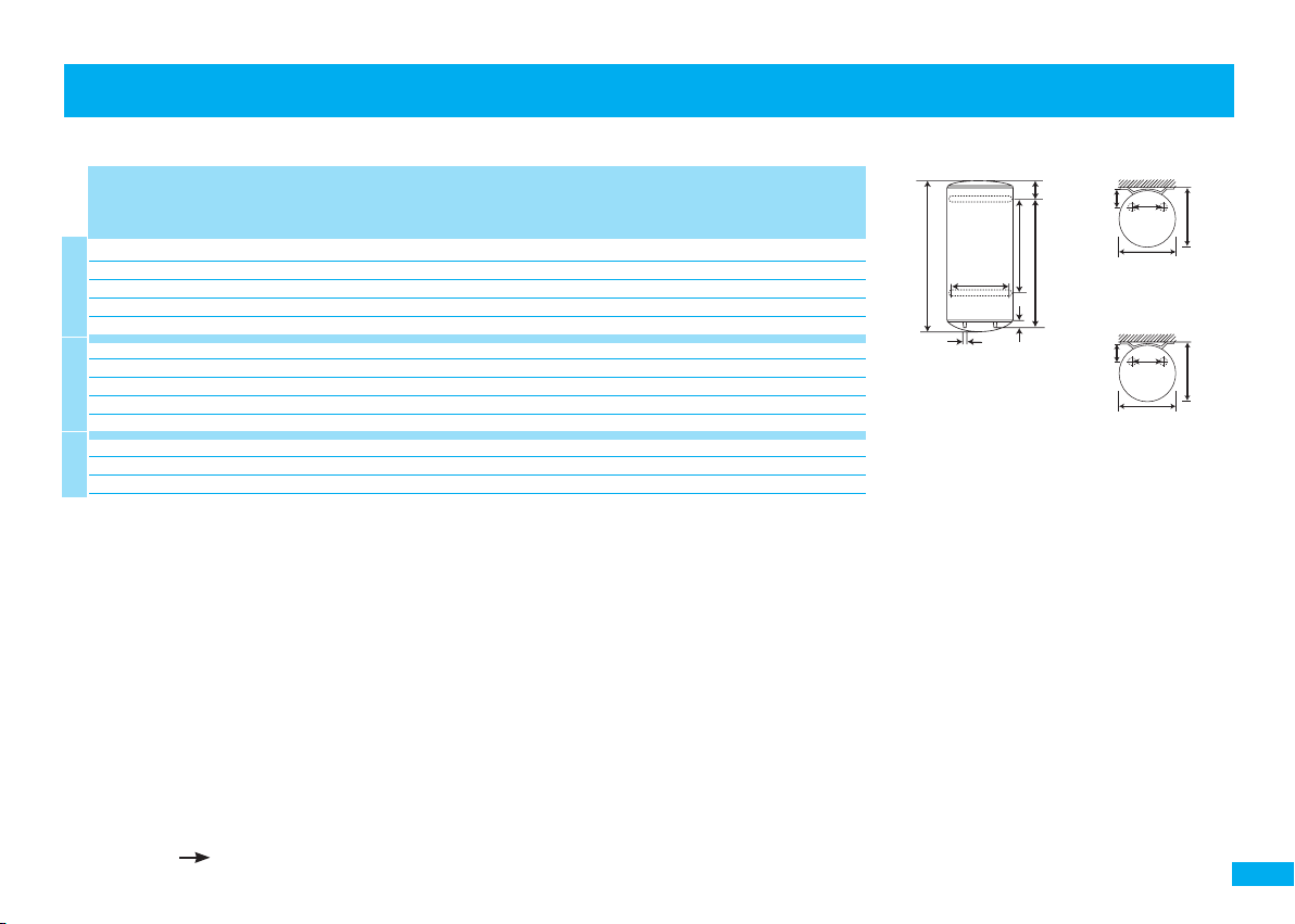
Verticaux muraux Cor-Email, CEB, CES / Cor-Email, CEB, CES Vertical wall mounted units / Verticale muurboilers Cor-Email, CEB, CES
CAPACITÉ PUISSANCE (W) ALIMENTATION
CAPACITY POWER (W) POWER SUPPLY
INHOUD VERMOGEN (W) VOEDING
A* B C D E
(2)
CONSOMMATION D’ENTRETIEN
(2)
CONSUMPTION FOR STEADY TEMP
(2)
VERBRUIK HANDHAVING TEMPERATUUR
50 l 1200 MO 0,82 576 - 35 368 156 22
75 l 1200 MO 1,02 742 - 35 570 120 27
100 l 1200 MO 1,25 908 - 35 748 113 32
150 l 1800 EasyTri
Cor-EmailCEB
200 l 2400 EasyTri
(3)
1,59 1241 798 35 1048 146 41
(3)
50 l 1200 MO 0,80 576 - 35 368 156 22
75 l 1200 MO 1,05 742 - 35 570 120 27
100 l 1200 MO 1,25 908 - 35 748 113 32
150 l 1600 MO/TC 1,65 1241 798 35 1048 146 41
200 l 2400 MO/TC
100 l 1200 MO 1,27 908 - 35 748 113 32
150 l 1800 MO 1,64 1241 798 35 1048 146 41
CES
200 l 2400 MO 1,94 1568 798 35 1048 473 51
* Hauteur sur trépied, ajouter 492 mm. / Height on tripod, add 492 mm. / Hoogte op driepoot, +492 mm.
(1) KWh/24h à 65°C - (1) KWh/24h at 65°C - (1) kWh/24 h bij 65 °C
(2) Alimentation MO : 230 V monophasé
• Alimentation TC - Tous courants, livré triphasé 400 V commutable en monophasé 230 V
MO power supply : 230 V single phased
• TC power supply - all types of power supplies, delivered 400 V three phase switchable to 230 V single phase
Voeding MO = 230 V eenfasig
• Voeding TC = alle stroomtypes, bij de levering driefasig 400 V, overschakelbaar op eenfasig 230 V
(3) Base 240V. Triphasé 400V possible avec kit EasyTri / Base 240V. 400 V three-phase possible with kit EasyTri / Basis 240V. 400V driefasig mogelijk
met de EasyTri kit P. 15
(1)
DIMENSIONS (mm) POIDS NU (KG)
(1)
DIMENSIONS (mm) WEIGHT EMPTY (KG)
(1)
AFMETINGEN (mm) NAAKT GEWICHT (KG)
1,94 1568 798 35 1048 473 51
1,93 1568 798 35 1048 473 51
E
175
440
B
D
Cor-Email 50 à 150 l
CEB 50 à 200 l
CES 100 à 200 l
C
179
Cor-Email 200 l
A
ø3/4”
230
230
513
529
505
533
3
Page 4
CARACTéRISTIqUES TEChNIqUES / TEChNICAL ChARACTERISTICS / TEChNISChE KENMERKEN
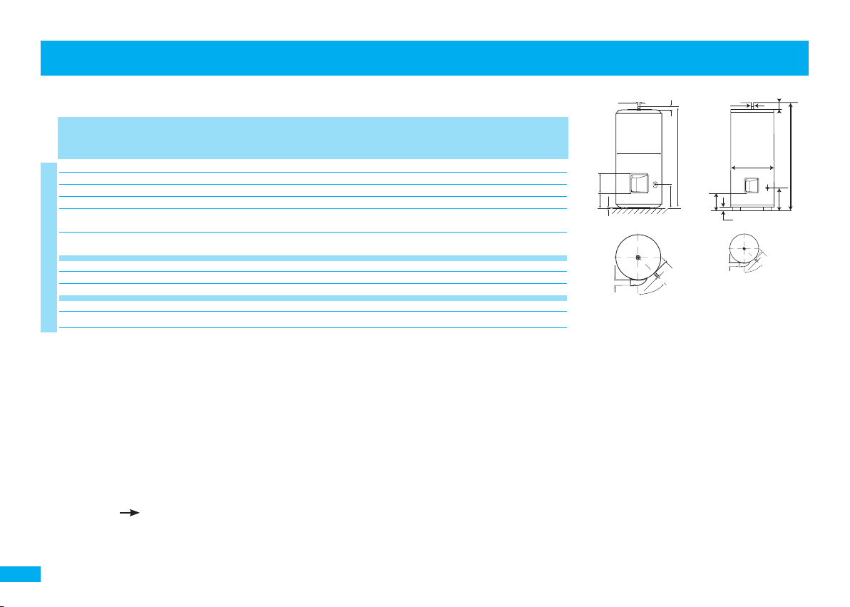
Cor-Email, CEB, CES à poser / Floor-standing units Cor-Email, CEB, CES / Boilers op pootjes Cor-Email, CEB, CES
CAPACITÉ PUISSANCE (W) ALIMENTATION
CAPACITY POWER (W) POWER SUPPLY
INHOUD VERMOGEN (W) VOEDING
A* B C D E F
150 l 1800 EasyTri
200 l 2400 EasyTri
250 l 3000 EasyTri
300 l 3000 EasyTri
400 l 5000 TC 2,70 1695 cf. schéma 124
(blindée/shielded/
geblindeerde weerstand
Cor-EmailCEB
500 l 5000 TC 3,80 2048 cf. schéma 148
(blindée/shielded/
geblindeerde weerstand
)
)
(2)
CONSOMMATION D’ENTRETIEN
(2)
CONSUMPTION FOR STEADY TEMP
(2)
VERBRUIK HANDHAVING TEMPERATUUR
(3)
1,59 1033 575 191 31 10 2 40
(3)
1,81 1288 575 191 31 10 2 51
(3)
2,07 1529 575 191 31 10 2 57
(3)
2,50 1791 575 191 31 10 2 67
200 l 2200 MO 2,45 1290 567 191 31 10 2 51
250 l 3300 MO/TC 2,23 1529 567 191 31 10 2 57
300 l 3300 MO/TC
250 l 3000 MO/TC 2,22 1529 575 191 31 10 2 57
CES
300 l 3000 MO/TC
* Hauteur sur trépied, ajouter 492 mm. / Height on tripod, add 492 mm. / Hoogte op driepoot, +492 mm.
(1) KWh/24h à 65°C - (1) KWh/24h at 65°C - (1) kWh/24 h bij 65 °C
(2) Alimentation MO : 230 V monophasé
• Alimentation TC - Tous courants, livré triphasé 400 V commutable en monophasé 230 V
MO power supply : 230 V single phased
• TC power supply - all types of power supplies, delivered 400 V three phase switchable to 230 V single phase
Voeding MO = 230 V eenfasig
• Voeding TC = alle stroomtypes, bij de levering driefasig 400 V, overschakelbaar op eenfasig 230 V
(3) Base 240V. Triphasé 400V possible avec kit EasyTri / Base 240V. 400 V three-phase possible with kit EasyTri / Basis 240V. 400V driefasig mogelijk
met de EasyTri kit P. 15
(4) Changement de thermostat obligatoire / Obligatory to change thermostat / Verpflicht om van thermostaat te veranderen
(4)
2,48 1791 567 191 31 10 2 67
(1)
DIMENSIONS (mm) POIDS NU (KG)
(1)
DIMENSIONS (mm) WEIGHT EMPTY (KG)
(1)
AFMETINGEN (mm) NAAKT GEWICHT (KG)
2,50 1791 567 191 31 10 2 67
250
C
E
ø3/4”
ø B
150 à 300 l
74
ø1”
D
300*
A
347
25
26
678
315
400 à 500 l
F
60
ø3/4”
70°
α=45
31
ø1”
4
Page 5
691
CARACTéRISTIqUES TEChNIqUES / TEChNICAL ChARACTERISTICS / TEChNISChE KENMERKEN
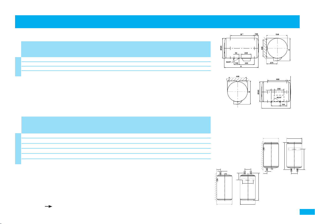
Horizontaux Cor-Email / Cor-Email Horizontal units / Horizontale boilers Cor-Email
CAPACITÉ PUISSANCE (W) ALIMENTATION
CAPACITY POWER (W) POWER SUPPLY
INHOUD VERMOGEN (W) VOEDING
A B** C D
75 l 1200 MO 1,01 691 480 580 600 26
100 l 1800 EasyTri
150 l 1800 EasyTri
Cor-Email
200 l 2100 EasyTri
(2)
CONSOMMATION D’ENTRETIEN
(2)
CONSUMPTION FOR STEADY TEMP
(2)
VERBRUIK HANDHAVING TEMPERATUUR
(3)
1,28 860 600 580 600 34
(3)
1,60 1182 800 580 600 45
(3)
Petites Capacités (sur ou sous évier) / Small tanks (above or under sink) / Kleine inhoud (boven of onder gootsteen)
CAPACITÉ PUISSANCE (W) ALIMENTATION
CAPACITY POWER (W) POWER SUPPLY
INHOUD VERMOGEN (W) VOEDING
A B** C D E
10 l sous/und/ond 2000 MO 0,63 456 255 218 262 64 7
10 l sur/abov./bov. 1600 MO 0,48 456 255 289 262 64 7
15 l sous/und/ond 2000 MO 0,68 496 287 218 294 70 9
CEB
15 l sur/abov./bov. 2000 MO 0,53 496 287 327 294 70 9
30 l sur/abov./bov. 2000 MO 0,73 623 338 463 345 81 12,5
50 l sur/abov./bov. 2000 MO 0,76 918 338 750 345 81 17,2
* Hauteur sur trépied, ajouter 492 mm. / Height on tripod, add 492 mm. / Hoogte op driepoot, +492 mm.
(1) KWh/24h à 65°C - (1) KWh/24h at 65°C - (1) kWh/24 h bij 65 °C
(2) Alimentation MO : 230 V monophasé
• Alimentation TC - Tous courants, livré triphasé 400 V commutable en monophasé 230 V
MO power supply : 230 V single phased
• TC power supply - all types of power supplies, delivered 400 V three phase switchable to 230 V single phase
Voeding MO = 230 V eenfasig
• Voeding TC = alle stroomtypes, bij de levering driefasig 400 V, overschakelbaar op eenfasig 230 V
(3) Base 240V. Triphasé 400V possible avec kit EasyTri / Base 240V. 400 V three-phase possible with kit EasyTri / Basis 240V. 400V driefasig mogelijk
met de EasyTri kit P. 15
(2)
CONSOMMATION D’ENTRETIEN
(2)
CONSUMPTION FOR STEADY TEMP
(2)
VERBRUIK HANDHAVING TEMPERATUUR
(1)
DIMENSIONS (mm) POIDS NU (KG)
(1)
DIMENSIONS (mm) WEIGHT EMPTY (KG)
(1)
AFMETINGEN (mm) NAAKT GEWICHT (KG)
2,06 1509 1050 580 600 56
(1)
DIMENSIONS (mm) POIDS NU (KG)
(1)
DIMENSIONS (mm) WEIGHT EMPTY (KG)
(1)
AFMETINGEN (mm) NAAKT GEWICHT (KG)
100 A 200 l
Fixation Plafond
Ceiling mounting
Bevestiging aan plafond
sur évier
above sink
boven gootsteen
E
G1/2“
C
D
100
184
ØB
E
sous évier
under sink
onder gootsteen
A
46
D
G1/2“
75 l
90
195
ØB
A
C
100
5
Page 6

MISE EN PLACE / INSTALLATION / INSTALLATIE
• Installer l’appareil dans un local à l’abri du gel.
• Pour les appareils muraux (verticaux et horizontaux), s’assurer que la cloison est capable de
supporter le poids de l’appareil rempli d’eau.
• Si l’appareil doit être installé dans un local humide ou un emplacement dont la température
ambiante est en permanence à plus de 35°C, prévoir une aération de ce local.
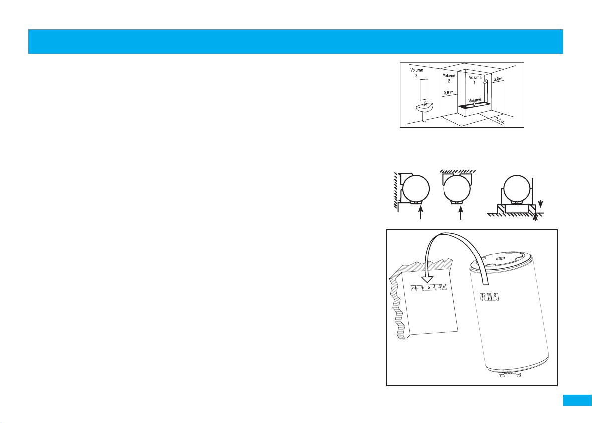
• Installation dans la salle de bains : 4 volumes sont définis pour implanter des appareils
suivant leurs caractéristiques. Nos chauffe-eau électriques peuvent être installés dans tous les
volumes (hors vol. 0 = baignoire) ci-dessous référencés, selon leur classe suivant les consignes
d’installation de la norme NF C15-100, tableau 701-4 et règle 701-5. (FIG. 1)
FIXATION D’UN APPAREIL VERTICAL MURAL
Chauffe-eau* et ballon à échangeur
• Laisser au-dessous des extrémités des tubes de l’appareil un espace libre au moins égal à
300 mm (jusqu’à 100 l) / 480 mm (150 et 200 l).
• Fixer l’appareil au mur par 4 boulons Ø 10 mm préalablement scellés (2 boulons seulement
pour les modèles 50, 75 et 100 l).
• Les appareils peuvent être montés sur trépied (en option). Il est cependant obligatoire de
fixer au mur l’étrier supérieur de l’appareil pour éviter tout basculement.
• Il est possible de remplacer d’anciens appareils verticaux muraux sans refaire le perçage grâce
à un système de pattes de transfert (disponible en option).
POSE D’UN CHAUFFE-EAU À POSER
• L’appareil doit être installé en position strictement verticale avec accessibilité à l’équipement
électrique et au groupe de sécurité.
CHAUFFE-EAU HORIZONTAL cf. Figure 2
DIFFÉRENTES POSSIBILITÉS D’INSTALLATION
ATTENTION : une fois le chauffe-eau mis en place, les têtes de raccordement hydraulique
doivent impérativement se trouver en position strictement verticale en dessous de l’appareil.
PETITES CAPACITÉS
Fixation murale : fixer l’étrier sur le mur à l’aide de goujons M8, préalablement scellés et
d’écrous M8. Attention : on ne peut pas mettre un chauffe-eau sur évier en lieu et place d’un
chauffe-eau sous-évier et inversement. (FIG. 3)
• Install the unit in a room protected from frost.
• For wall mounted units (vertical and horizontal), make sure that the wall is strong enough to
support the weight of the unit full of water.
• If the water heater is to be installed in a damp room or in a location in which the ambient
temperature is continuously above 35°C, then ventilate this room.
• Installation in the bathroom: four volumes are defined in which units may be installed, depen-
ding on their characteristics. Our electric water heaters may be installed in all volumes (apart
from volume 0 = bath) shown below, in accordance with their class and with the installation
instructions in NF standard C15-100, table 701-4 and rule 701-5.
MOUNTING OF A WALL MOUNTED VERTICAL MODEL
Water heater* and exchanger tank
• Leave a free space of at least 300 mm (for 100 l models) or 480 mm (for 150 and 200 l models)
below the ends of the water heater tubes.
• Fix the unit to the wall using four Ø 10 mm bolts already anchored into the wall (only 2 bolts
for 50, 75 and 100 l models).
• Units may be mounted on a tripod (optional). However, the upper stirrup of the unit
must be attached to the wall to prevent the unit from tipping.
• Old wall mounted units can be replaced without drilling new holes by using a load transfer
system (available as option).
INSTALLATION A FLOOR-STANDING WATER HEATER
• The unit must be installed in the strictly vertical position, and the electrical equipment for the
safety device must be accessible.
HORIZONTAL WATER HEARTER figure 2
SMALL TANKS
Wall attachment: fix the stirrups to the wall using M8 studs anchored to the wall and M8 nuts.
Warning: an under sink model cannot be replaced by an above sink model and vice
versa. (FIG. 3)
(*hors petites capacités) / (*except for small tanks) / (*behalve kleine modellen)
6
Page 7
MISE EN PLACE / INSTALLATION / INSTALLATIE
• Installeer het toestel in een vorstvrije ruimte.
• Controleer voor de bevestiging van (verticale en horizontale) wandmodellen of de muur sterk genoeg is om het
gewicht van het met water gevulde toestel te dragen.
• Wordt het toestel opgesteld in een vochtige ruimte of in een ruimte waar de omgevingstemperatuur constant
meer dan 35 °C bedraagt, dan is een ventilatiesysteem noodzakelijk.
• Installatie in een badkamer: voor de opstelling van een toestel dient met 4 volumes rekening te worden gehouden,
afhankelijk van de kenmerken van het toestel. Onze elektrische boilers mogen in alle onderstaande volumes worden opgesteld (behalve in volume 0 = het bad), afhankelijk van hun categorie en volgens de installatierichtlijnen
van de norm NF C15-100, tabel 701-4 en regel 701-5.
BEVESTIGING VAN EEN VERTICAAL WANDMODEL
Boiler* en Ketel met warmtewisselaar
• Laat onder de uiteinden van de buizen van het toestel een ruimte van ten minste 300 mm (100 l) of 480 mm
(150 -200 l) vrij.
• Bevestig het toestel aan de wand met behulp van 4 vooraf in de muur gemetste bouten Ø 10 mm (2 bouten
volstaan voor de modellen van 50, 75 en 100 l).
• De toestellen kunnen op een (afzonderlijk te verkrijgen) driepoot worden opgesteld. Het is verplicht ze in dat
geval aan de muur te bevestigen met behulp van de bovenste bevestigingshaak om omkantelen
te vermijden.
• Het is mogelijk een oud verticaal wandmodel te vervangen zonder nieuwe gaten te moeten boren dankzij de
(afzonderlijk te verkrijgen) verloophaken.
INSTALLATIE VAN EEN BOILER OP POOTJES
• Stel het toestel perfect verticaal op en zorg ervoor dat de elektrische onderdelen van het veiligheidselement vrij
toegankelijk blijven.
HORIZONTALE BOILER figuur 2
KLEINE MODELLEN
Wandbevestiging: Zet de bevestigingshaak aan de wand vast met behulp van vooraf in de muur gemetste M8 pennen
en M8 moeren. Let op! Een boiler voor boven de gootsteen mag in geen geval onder de gootsteen
geïnstalleerd worden of omgekeerd. (FIG.3)
(FIG. 1)
(FIG. 2)
450
450 450
(*hors petites capacités) / (*except for small tanks) / (*behalve kleine modellen)
(FIG. 3)
7
Page 8

RACCORDEMENT hYDRAULIqUE / WATER CONNECTIONS / AANSLUITING WATERLEIDINGEN
Avant de procéder au raccordement hydraulique, il est absolument indispensable de
bien nettoyer les tuyauteries d’alimentation
afin de ne pas risquer d’introduire dans la
cuve du chauffe-eau des particules métalliques ou autres.
ATTENTION : Ne pas raccorder directement
aux canalisations en cuivre les tubes eau
chaude (repère rouge) et eau froide (repère
bleu) du chauffe-eau pour éviter les couples galvaniques fer/cuivre. Il est obligatoire
d’équiper le tube eau chaude d’un raccord
diélectrique (généralement fourni avec l’appareil hors petites capacités) et le tube eau
froide d’un groupe de sécurité.
Dans le cas d’utilisation de tuyaux PER, la
pose d’un régulateur thermostatique en sortie de chauffe-eau est fortement conseillée. Il
sera réglé en fonction des performances du
matériau utilisé.
En cas de corrosion des filetages des tubes
non équipés de ces protections, notre garantie ne pourrait être appliquée.
Quel que soit le type d’installation, elle doit
comporter un robinet d’arrêt sur l’alimentation d’eau froide, en amont du groupe de
sécurité.
Before making the water connections, it is
essential to ensure that the supply pipes
are thoroughly clean, to avoid any risk
of metallic or other particles entering the
water heater tank.
WARNING : do not connect water heater
hot water pipes (red mark) and cold water
pipes (blue mark) directly to copper pipes,
to prevent iron-copper galvanic couples.
The hot water pipe must be fitted with
a dielectric connector (supplied with the
equipment except for small tanks) and the
cold water pipe with a safety valve.
If using PER pipes, we strongly recommend that a thermostatic regulator be
fitted to the water heater outlet. It will be
set according to the performances of the
equipment used.
Our guarantee will be invalid if
there is any corrosion on the threads
of pipes not fitted with these protectives devices.
Regardless of the installation type, it must
include a stop tap on the cold water supply, before the safety valve.
Alvorens het toestel op de waterleidingen
aan te sluiten, is het absoluut noodzakelijk
de toevoerbuizen schoon te maken om te
vermijden dat metalen of andere deeltjes in
de tank van de boiler terecht komen.
LET OP ! Sluit de warmwaterbuizen (rood
kenteken) en de koudwaterbuizen (blauw
kenteken) van de boiler in geen geval
rechtstreeks op koperen buizen aan om te
vermijden dat een galvanisch koppel (ijzer/
koper) ontstaat. Het is verplicht de warmwaterbuis van een diëlektrische koppeling
te voorzien (bij het toestel geleverd, behalve
bij de kleine modellen) en de koudwaterbuis
van een veiligheidselement.
Indien VPE-leidingen gebruikt worden,
wordt de inbouw van een thermostaatregelaar aan de uitgang van de boiler van
harte aanbevolen. Deze moet afgesteld
worden aan de hand van de prestaties van
het gebruikte materiaal.
Krijgen de schroefdraden van buizen
die niet met dergelijke beveiligingen
zijn uitgerust, te lijden onder corrosie,
dan geldt onze garantie niet.
Het is bij alle soorten installaties verplicht op
de koudwatertoevoer, vóór het veiligheidselement, een afsluitkraan te voorzien.
8
Page 9
RACCORDEMENT hYDRAULIqUE / WATER CONNECTIONS / AANSLUITING WATERLEIDINGEN
Un chauffe-eau à accumulation peut être
utilisé de deux façons :
1 - sous pression quand il doit desservir plusieurs postes d’eau. L’installation doit comporter un réducteur de pression si la pression d’alimentation est supérieure à 5 bar
(0.5 MPa). Le réducteur de pression doit être
monté au départ de la distribution générale. Une pression de 3 à 4 bar (0.3 à 0.4
MPa) est recommandée. L’installation doit
A storage water heater may be used in two
different ways :
1 - pressurized when it supplies several
taps. The installation must include a pressure reducer if the supply pressure exceeds
5 bar (0.5 MPa). The pressure reducer
must be installed at the outlet of the
general distribution. A pressure of 3 to
4 bar (0.3 to 0.4 MPa) is recommended.
The installation must be done using a new
Een boiler kan op twee manier worden
gebruikt :
1 - onder druk, wanneer hij water moet
produceren dat op verschillende plaatsen
kan worden afgetapt. De installatie moet
voorzien zijn van een reduceerventiel indien
de druk meer dan 5 bar (0.5 MPa). bedraagt.
Het reduceerventiel moet gemonteerd
worden aan het begin van de algemene waterdistributie. Wij raden een
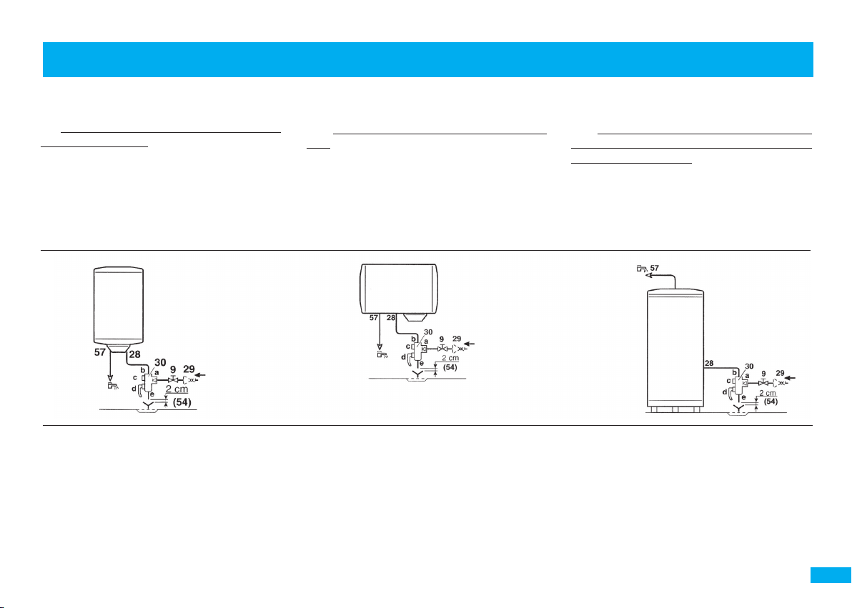
9. Vanne de sectionnement
28. Entrée eau froide
29. Réducteur de pression
54. Rupture de charge de type YA (règlement sanitaire)
57. Sortie eau chaude sanitaire
30. Groupe de sécurité taré à 7 bar (0.7 MPa)
a Arrivée eau froide intégrant un clapet anti-retour
b Raccordement à l’entrée eau froide du préparateur
c Robinet d’arrêt
d Soupape de sécurité et vidange manuelle
e Orifice de vidange
9. Valve
28. Domestic cold water inlet
29. Pressure reducer
54. End of the discharge pipe
57. Domestic hot water output
30.
Sealed safety device calibrated to 7 bar (0.7 MPa)
a Cold water inlet with integrated non-return valve
b Connection to the tank’s cold water inlet
c Stop valve
d Safety valve and manual drain
e Drain hole
9. Afsluiter
28. Sanitair-koudwateringang
29. Reduceerventiel
54. Einde van de ontlastleiding
57. Sanitair warm water uitgang
30.
Veiligheidsgroep, getarreerd en verzegeld op 7 bar (0.7 MPa)
a
Aanvoer koud water met ingebouwde terugslagklep
b Aansluiting op de ingang sanitair koud water van de boiler
c Stopkraan
d Veiligheidsklep en handmatige aftapkraan
e Aftapopening
9
Page 10

RACCORDEMENT hYDRAULIqUE / WATER CONNECTIONS / AANSLUITING WATERLEIDINGEN
être effectuée avec un groupe de sécurité
taré à 7 bar (0.7 MPa) (non fourni ), neuf, de
dimensions appropriées à la capacité (petites
capacités : 1/2”, 50 à 300 l : 3/4”, 500 l :
1”), et portant la marque NF (norme NF EN
1487).
Son installation doit être faite rigoureu-
sement selon les schémas ci-après. Il est
obligatoire de placer le groupe de sécurité
directement sur l’entrée d’eau froide (NFC
15-100 ch 559-3) et à l’abri du gel.
- En outre, il ne faut absolument pas qu’en
cas de surpression, l’écoulement en résultant puisse être freiné. Ceci implique que le
tube de vidange ait une pente continue et
suffisante, et un diamètre adapté au débit.
2 - en écoulement libre, pour alimenter un
seul point d’eau : Ce type d’installation est
spécialement adapté aux chauffe-eau de
la gamme des petites capacités de 10, 15,
30 et 50 l, sur-évier et sous-évier suivant les
modèles, lorsqu’ils ne peuvent être installés
sous pression. L’installation doit être réalisée
avec un robinet mélangeur spécifique. Dans
ce cas, il n’y a pas lieu d’utiliser un groupe
de sécurité.
safety valve set to 7 bar (0.7 MPa) not
supplied, with dimensions appropriate to
the tank (1/2» for small tanks, 3/4» for 50
to 300 l models, and 1» for 500 l models),
and bearing the NF mark (standard
EN 1487
It must be installed strictly respecting the
following diagrams. It is recommended
that the safety valve should be placed directly on the cold water inlet
(NFC 15-100 ch 559-3) and protected from frost.
- Furthermore, if there is an overpressure,
the resulting flow must never be hindered.
This means that the drain pipe should
have a continuous and sufficient slope,
and its diameter should be appropriate
for the flow.
2 - in free flow, when only a single water
tap is to be supplied. This type of installation is specifically adapted to point-of-use
water heaters (i.e. capacities of 10, 15,
30 and 50 l) that cannot be installed as
unvented systems (i.e. pressurised). The
installation must be made with a special
mixing tap. In this case there is no need
for a safety valve.
).
NF
druk van 3 tot 4 bar (0.3 tot 0.4 MPa) aan.
De installatie moet voorzien zijn van een op
7 bar (0.7 MPa) getarreerd (niet bijgeleverd)
veiligheidselement dat het merkteken NF
(norm NF EN 1487) draagt en waarvan de
afmetingen aan de inhoud zijn aangepast
(kleine inhoud : 1/2», 50 tot 300 l : 3/4»,
500 l: 1»).
Bij de installatie dienen volgende schema’s
nauwkeurig in acht te worden genomen.
Het is verplicht het veiligheidselement
rechtstreeks op de koudwatertoevoer
te plaatsen (NFC 15-100 ch 559-3) en
buiten vorst.
- Bovendien mag het wegvloeiend water bij
overdruk in geen geval worden afgeremd.
Dat betekent dat de aftapbuis constant en
op toereikende wijze moet afhellen en dat
de diameter geschikt moet zijn voor het
debiet.
2 - met een spontane waterafvoer, voor
één enkele waterkraan. Dit soort installatie
is speciaal aangepast voor de kleine inhoud
boilers van 10, 15, 30 en 50 liters, boven en
onder de gootsteen volgens de modellen,
toen ze kunnen niet onder druk geplaatst
worden. In dit geval is de installatie van een
specifieke mengkraan noodzakelijk; een veiligheidselement is echter overbodig.
10
Page 11

RACCORDEMENT hYDRAULIqUE / WATER CONNECTIONS / AANSLUITING WATERLEIDINGEN
EcoulEmEnt librE (*)
FrEE Flow (*)
SpontanE aFvoEr (*)
6
7
1
1
Arrivée eau froide / Cold water inlet / Koudwatertoevoer
2
Robinet d’arrêt / Stop tap/ Afsluitkraan
3
Réducteur de pression éventuel / Pressure reducer if necessary / Eventueel reduceerventiel
4
Groupe de sécurité / Safety valve / Veiligheidselement
5
Entonnoir / Funnel / Trechter
6
Départ eau chaude / Hot water outlet / Warmwaterafvoer
7
Manchon diélectrique obligatoire / Compulsory dielectric connection / Verplichte diëlektrische mof
* Ces schémas montrent l’installation des appareils sous
évier.
Pour les modèles sur-évier, les raccordements sont sous
l’appareil comme dans le cas des appareils muraux.
* These diagrams show the installation of under sink models.
Connections for above sink models are under the water
heater as in the case of wall mounted equipment.
SouS prESSion (*)
mainS prESSurE (*)
ondEr druk (*)
6
7
vErticaux muraux
vErtical wall mountEd
vErticalE wandmodEllEn
1
4
3
2
5
* Deze schema’s illustreren de installatie van toestellen onder
de gootsteen.
De installatie van toestellen voor boven de gootsteen is
dezelfde als bij wandmodellen.
7
6
4
2
3
5
1
11
Page 12

bRANChEMENT éLECTRIqUE / ELECTRICAL CONNECTIONS / ELEKTRISChE AANSLUITINGEN
Le chauffe-eau ne peut être branché et fonctionner
que sur un réseau à courant alternatif.
ATTENTION : LE RACCORDEMENT DE
L’ALIMENTATION S’EFFECTUE SUR LE BORNIER POUR
LES MODÈLES AVEC BORNIER, SUR L’ENTRÉE DU
THERMOSTAT POUR LES MODÈLES SANS BORNIER
ET EN AUCUN CAS SUR LA RESISTANCE OU À LA
SORTIE DU THERMOSTAT. AUCUNE INTERVENTION
SUPPLEMENTAIRE N’EST A PREVOIR EXCEPTÉS LES
CHANGEMENTS DE COUPLAGE SI NECESSAIRE.
POUR LES CHAUFFE-EAU A.C.I., LE CIRCUIT A.C.I. EST
PRÉCABLÉ EN USINE.
• Si le chauffe-eau est un modèle «Tous Courants», veiller à ce
que le câblage électrique de l’appareil soit adapté à la tension
d’alimentation du réseau.
• Le chauffe-eau doit être relié à une canalisation fixe
ou une gaine annelée normalisée jusqu’au logement
calibré du capot par un câble rigide (section des
conducteurs : minimum 2,5 mm2 et 4 mm2 sur le
500 l).
• La mise à la terre est obligatoire. Une borne spéciale
portant le repère
• L’installation doit comporter en amont du chauffeeau un dispositif de coupure omnipolaire avec une
distance d’ouverture des contacts d’au moins 3 mm
(disjoncteur différentiel de 30mA).
Dans le but d’optimiser la consommation d’énergie,
le thermostat a été réglé pour que la température
de l’eau dans le chauffe-eau soit limitée à 65° C (±
5°C); la résistance à la corrosion et à l’entartrage s’en
trouve améliorée.
Le thermostat ne doit sous aucun prétexte subir
d’éventuels réglages ou réparations en dehors de
nos usines à l’exception du réglage normal par
est prévue à cet effet.
The water heater can only be connected to and
operate on an AC network.
WARNING: THE POWER SUPPLY IS CONNECTED
TO THE TERMINAL BLOCK FOR MODELS WITH A
TERMINAL BLOCK, TO THE THERMOSTAT INPUT
FOR MODELS WITHOUT A TERMINAL BLOCK, AND
NEVER TO THE ELEMENT OR THE THERMOSTAT
OUTPUT. NO ADDITIONAL WORK IS REQUIRED,
EXCEPT FOR COUPLING CHANGES IF NECESSARY.
THE A.C.I. CIRCUIT ON A.C.I. MODELS IS PREWIRED
IN THE FACTORY.
• If the water heater is an «All Currents» model,
check that its electric wiring is correctly adjusted for
the network power supply voltage.
• The water heater must be connected to a fixed pipe
through a rigid cable (minimum conductor cross-section = 2.5 mm≈ or 4 mm2 for the 500 l tank).
• Earthing is compulsory. A special terminal marked
is provided for this purpose.
• The installation must include an all-pole circuit
breaking device before the water heater, with a
contact opening distance of at least 3 mm. (differential circuit breaker of 30mA).
The thermostat was set so that the water temperature in the water heater is limited to 65°C (± 5 °C) in
order to optimize energy consumption; this improves resistance to corrosion and to scaling.
The thermostat must not be modified or repaired in
any way outside our factories for any reason whatsoever, except for normal adjustment by rotating
the index (which should only be done by the installer
after switching the equipment off). Failure to respect
this clause will invalidate the guarantee.
SMALL TANKS : The thermostat is set to 65°C (±5°C)
(CONfORME NfC 15-100)
De boiler mag uitsluitend worden aangesloten op
wisselstroom.
LET OP ! BIJ DE MODELLEN MET EEN
AANSLUITKLEMMENBLOK MOET HET SNOER OP HET
AANSLUITKLEMMENBLOK WORDEN AANGESLOTEN,
BIJ MODELLEN ZONDER AANSLUITKLEMMENBLOK
OP DE INGANG VAN DE THERMOSTAAT. IN GEEN
GEVAL OP DE WEERSTAND OF OP DE UITGANG VAN
DE THERMOSTAAT. VERDER BLIJFT DE ELEKTRISCHE
INSTALLATIE ONGEWIJZIGD, BEHALVE INDIEN DE
KOPPELING VERANDERD DIENT TE WORDEN. BIJ
A.C.I. BOILERS IS HET A.C.I. CIRCUIT IN DE FABRIEK
VOORBEKABELD.
• Is de boiler een TC-model (alle stroomtypes),
controleer of de elektrische draden aan de netspanning zijn aangepast
• De boiler moet op een vaste leiding zijn aangesloten d.m.v. een onbuigzame kabel (doorsnede van
de geleiders: minimum 2,5 mm≈ en 4 mm≈ bij het
model 500 l).
• De aarding van het toestel is verplicht. Daarvoor is
een specifieke aansluitklem voorzien
• De installatie moet stroomopwaarts van de boiler
voorzien zijn van een schakelaar voor alle polen met
contactopeningen van ten minste 3 mm. (differentiële schakelaar van 30 mA)
Om het energieverbruik te optimaliseren werd
de thermostaat zo afgesteld dat de temperatuur van het water in de boiler beperkt blijft tot
65 °C (± 5 °C); zo blijft de weerstand beter bestand
tegen corrosie en kalkaanslag.
De thermostaat mag in geen geval worden bijgesteld
of hersteld buiten onze fabrieken; alleen de normale
afstelling door de installateur is toegestaan, d.w.z.
.
12
Page 13

bRANChEMENT éLECTRIqUE / ELECTRICAL CONNECTIONS / ELEKTRISChE AANSLUITINGEN
rotation de l’index (qui ne peut être effectué que par
l’installateur après mise hors tension de l’appareil).
Le non respect de cette clause supprime le bénéfice
de la garantie.
PETITES CAPACITÉS : Le thermostat est réglé en
usine à 65°C (± 5°C). Il vous est possible de modifier
ce réglage par la molette du thermostat. Diminuer
la température de réglage contribue à diminuer les
dépôts de calcaire. Le témoin de fonctionnement
reste allumé uniquement pendant la phase de chauffe.
COUPE-CIRCUIT THERMIQUE :
Tous nos chauffe-eau sont équipés d’un coupe-circuit
de sécurité qui déclenche l’arrêt du chauffe-eau si
la température atteint accidentellement une valeur
exagérée. En cas de déclenchement de la sécurité,
COUPER LE COURANT AVANT TOUTE OPÉRATION,
vérifier l’installation avant de procéder à son réarmement. Rétablir le courant. En cas de déclenchement
répétitif, faire remplacer le thermostat par une personne habilitée.
EN AUCUN CAS ON NE DOIT COURT-CIRCUITER
LA SÉCURITÉ
ACI : en cas de déclenchement en sécurité, remplacer le bloc thermostat électronique.
PETITES CAPACITÉS : Pour réarmer la sécurité, il est
nécessaire de retirer le capot, ensuite, appuyer sur
le bouton safety du thermostat. Après avoir réenclenché la sécurité, remettre le capot et rétablir le
courant. En cas de déclenchement répété, demander
l’intervention d’une personne habilitée.
in the factory. You can modify this setting using
the knurled knob on the thermostat. Reducing the
temperature will help to reduce deposited scale. The
operating light remains on only during the heating
phase.
TEMPERATURE CIRCUIT BREAKER :
All our water heaters are equipped with a safety temperature circuit breaker that switches the water heater
off if the temperature accidentally reaches an excessively high value. If the safety device trips, SWITCH
OFF THE POWER BEFORE DOING ANYTHING, and
then check the installation before resetting it. Switch
the power on again. Have the thermostat replaced
by a professional if it trips repeatedly.
NEVER SHORT CIRCUIT THE SAFETY DEVICE.
ACI : If the security system set off, change the electronique thermostat.
SMALL TANKS: The safety device is reset by moving
the cover, and then pressing on the safety button of
the thermostat. After resetting the safety device, put
the cover back on and switch the power on again.
Have the thermostat replaced by a professional if it
trips repeatedly.
(CONfORME NfC 15-100)
dat alleen hij de wijzer na uitschakeling van het toestel mag verdraaien. Door niet-naleving van deze
clausule vervalt de garantie.
Verwarmingsketels met een kleine capaciteit: de
thermostaat is in fabriek afgesteld op 65°C (±5°C).
U kunt deze afstelling wijzigen met behulp van het
kartelwieltje op de thermostaat. Een lager afgestelde
temperatuur leidt tot minder kalkaanslag. Het werkingscontrolelampje brandt uitshuitend tijdens het
verwarmen.
THERMISCHE BEVEILIGING:
Al onze boilers zijn voorzien van een beveiliging
die de boiler uitschakelt zodra per ongeluk een
overdreven temperatuur wordt bereikt. Treedt het
veiligheidssysteem in werking, ONDERBREEK IN DE
EERSTE PLAATS DE STROOM; de installatie mag pas
na een grondige controle opnieuw gereset worden.
Schakel het toestel opnieuw in. Doet het probleem
zich opnieuw voor, raadpleeg een bekwaam technicus om de thermostaat te laten vervangen.
HET VEILIGHEIDSSYSTEEM MAG IN GEEN GEVAL
KORTGESLOTEN WORDEN
ACI : Als het veiligheidssysteem in werking treedt, het
electronische thermostaatblok vervangen.
KLEINE MODELLEN: Om het veiligheidssysteem te
resetten is het noodzakelijk de kap die toegang
geven tot het veiligheidssysteem, te verwijderen om
vervolgens de safety knop van de thermostaat in
te drukken. Na het veiligheidssysteem opnieuw te
hebben ingeschakeld, de kap opnieuw aanbrengen
en het toestel inschakelen. Treedt het veiligheidssysteem opnieuw in werking, raadpleeg een bekwaam
technicus.
13
Page 14

bRANChEMENT éLECTRIqUE A.C.I. / A.C.I. ELECTRICAL CONNECTION / ELEKTRISChE AANSLUITINGEN A.C.I.
n MODELES A.C.I. Electronic
A.C.I. Electronic MODELS
A.C.I. Electronic MODELLEN
Verticaux muraux mono
Single phase wall mounted vertical models
Verticale muurboilers eenf.
Horizontaux
Horizontal models
Horizontale modellen
Horizontaux
Stables floor-standing
Op pootjes
PROCEDURE DE RACCORDEMENT
• Ce chauffe-eau est pré-câblé en 230 V~
monophasé. Pour du 400 V~ triphasé vous
devez remplacer la platine monophasée d’origine par un kit triphasé 400V~ (réf. 100001495).
La procédure d’installation de ce kit est détaillée
dans la notice jointe au kit.
• Raccorder les extrémités du câble sur le thermostat, aux bornes à vis prévues à cet effet (le
démontage du thermostat n’est pas nécessaire).
• Raccorder le fil de terre vert/jaune sur la borne
repère
photos page suivante.
14
, sur la porte du chauffe-eau. Voir
ALIMENTATION
POWER SUPPLY /VOEDING
MONO 230 V
230 V SINGLE PHASE
EENFASING 230 V.
A B
+
C D
+
C D
+
CONNECTION PROCEDURE
• The original connection for this water heater is
configured for 230 V~ single phase. For a 400 V~
three-phase connection you need to replace the
original single phase plate by a 400 V~three-phase
kit (ref. 100001495). Refer to the manual enclosed
with the kit for instructionss for installation.
• Connect the ends of the thermostat cables to
the screw terminals provided for this purpose
(there is no need to disassemble the thermostat).
• Connect the yellow/green earthing wire to the
terminal marked with the earthing symbol on
the door of the water heater. See pictures on
next page.
Réglage de la température
de l’eau /
Water temperature setting /
Instelling watertemperatuur
OBLIGATION :
Pour bénéficier de la garantie,
il est obligatoire de brancher
le système A.C.I.
OBLIGATION :
You must plug in the A.C.I.
system otherwise the
guarantee will not be valid.
VERPLICHT :
Om van de garantie gebruik te
kunnen maken dient u verplicht
het A.C.I. systeem aan te sluiten.
CONNECTION PROCEDURE
• De oorspronkelijke aansluiting voor deze boiler
is geschikt voor 230 V~ éénfasig. Voor een 400
V~ driefasige aansluiting dient u de oorspronkelijke éénfaseplaat vervangen door een 400
V~ driefasige ombouwkit (ref. 100001495). Zie
handleiding ombouwkit voor installatie.
• Sluit de uiteinden van de kabel aan op de thermostaat, op de twee hiervoor bestemde schroefklemmen (het is niet nodig the thermostaat te
demonteren).
• Sluit de groen/gele aardleiding aan op de plaats
met het aardesymbool op de deur van de boiler.
Zie volgende pagina.
Page 15

bRANChEMENT éLECTRIqUE A.C.I. / A.C.I. ELECTRICAL CONNECTION / ELEKTRISChE AANSLUITINGEN A.C.I.
Borne de terre / Earthing terminal / Aardingsklem
A B
EffECTUER LE RACCORDEMENT DE L’ALIMENTATION SUR LE bORNIER UNIqUEMENT /
CONNECT ThE POWER SUPPLY ONLY VIA ThE TERMINAL / DE STROOM ENKEL OP DE KLEMMENSTROOL ANSLUITEN
C D
Filerie de l’ACI / ICA wiring / Bedrading ACI
Voyant ACI / ICA pilot light / ACI signaalampje
Bornier d’alimentation (non polarisé) /
Supply termi,nal (not polarized) /
Stroomvoedingsklem (niet gepolariseerd)
Filerie élément chauffant / Heating element wiring
Bedrading verwarmingselement
Règlage de la température de l’eau / Water
temperature setting / Instelling watertemperatuur
Element chauffant / Heating element /
Verwarmingselement
Connecteur filerie élément chauffant /
Heating element wiring connector /
Aansluitklem bedrading verwarmingselement
Sonde température / Heat sensor /
Temperatuursensor
Borne de terre / Earthing terminal / Aardingsklem
Element chauffant / Heating element /
Verwarmingselement
Sonde température / Heat sensor /
Temperatuursensor
Bornier d’alimentation (non polarisé) /
Supply termi,nal (not polarized) /
Stroomvoedingsklem (niet gepolariseerd)
Filerie élément chauffant / Heating element wiring
Bedrading verwarmingselement
Connecteur filerie élément chauffant /
Heating element wiring connector /
Aansluitklem bedrading verwarmingselement
Filerie de l’ACI / ICA wiring / Bedrading ACI
Voyant ACI / ICA pilot light / ACI signaalampje
Règlage de la température de l’eau / Water
temperature setting / Instelling watertemperatuur
15
Page 16

bRANChEMENT éLECTRIqUE CEb, CES / CEb, CES ELECTRICAL CONNECTION / CEb, CES ELEKTRISChE AANSLUITINGEN
n MODELES BLINDÉS / SCHIELDED MODELS
GEBLINDEERDE MODELLEN
Verticaux muraux 50-200 l mono
CEB 50-200 l vertical wall mounted models single phase
Verticale muurboilers 50-200 l eenf.
Verticaux muraux 150 et 200 l tous courants
CEB 150 and 200 l vertical wall mounted all powers
Verticale muurboilers 150 en 200 l alle stroomtypes
CEB
200, 250 and 300 l floor-standing / Op pootjes 200, 250 en 300 l
Cor-Email
Op pootjes 400 en 500 l
Verticaux muraux 100-200 l mono
CES 100-200 l vertical wall mounted models single phase
Verticale muurboilers 100-200 l eenf.
CES
200, 250 et 300 l à poser / 200, 250 and 300 l floor-standing
400 et 500 l à poser / 400 & 500 l floor-standing /
250/300 l à poser / 300 l floor-standing / Op pootjes 300 l
ALIMENTATION / POWER SUPPLY / VOEDING
MONO TRIPHASE
SINGLE PHASE/ EENF. THREE PHASE/DRIEF.
A
B1
C1
D1
*
*
*
B2
C2
D2
E1
F1
F2
230 V
E1
230 V
A
* Passage de tri en mono : raccordement des fils noirs à modifier comme indiqué sur le schéma.
* Change from 3-phase to single phase : connection of black wires to be modified as shown on the drawing.
16
* Overschakeling van drief. naar eenf.: wijzig de aansluiting van de zwarte draden volgens het schema.
230 V
B1
Eau chaude
Hot water
Warm water
Eau froide
Cold water / Koud water
400 V
B2
*
Eau chaude
Hot water
Warm water
Eau froide
Cold water
Koud water
Schémas non contractuels
Diagrams not contractually binding
Niet contractuele schema’s
Page 17

bRANChEMENT éLECTRIqUE CEb, CES / CEb, CES ELECTRICAL CONNECTION / CEb, CES ELEKTRISChE AANSLUITINGEN
C1
D1
230 V
230 V
C2
D2
400 V
400 V
F2
230V
F1
400 V
Schémas non contractuels
Diagrams not contractually binding
Niet contractuele schema’s
ATTENTION : Changement de thermostat - Kit réf. : 97868719
WARNING : Change of thermostat - Kit ref. : 97868719
LET OP : Verandering van thermostaat : Kit verwijzing : 97868719
17
Page 18

bRANChEMENT éLECTRIqUE PETITES CAPACITéS / ELECTRICAL CONNECTION fOR SMALL TANKS / ELEKTRISChE AANSLUITINGEN KLEINE MODELLEN
MISE EN SERVICE / START UP / INDIENSTSTELLING
ATTENTION : NE JAMAIS METTRE SOUS TENSION LE
CHAUFFE-EAU SANS EAU.
Avant de mettre le chauffe-eau sous tension, le remplir
complètement d’eau en ayant auparavant ouvert les robinets d’eau chaude ; ne refermer les robinets que lorsque
l’écoulement s’effectue régulièrement et sans bruit de
tuyauterie (purge complète de l’air et nettoyage des tuyauteries).
Lorsque le remplissage est terminé, mettre le contacteur
électrique en marche forcée et attendre environ 30 minutes
(pression de l’installation atteignant 7 bar - 0.7 MPa).
Pour les chauffe-eau équipés de l’A.C.I., vérifier le bon fonctionnement de la protection contre la corrosion en coupant
18
WARNING : NEVER SWITCH THE WATER HEATER
ON WITH NO WATER.
Before switching the water heater on, open hot water
taps and fill it completely with water; do not close the
valves until flow takes place uniformly and there are no
more pipe noises (all air purged and pipes cleaned).
When filling is finished, put the electrical contactor into
forced operation and wait for about 30 minutes (installation pressure reaches 7 bar - 0.7 MPa).
For water heaters fitted with A.C.I., check that the anticorrosion protection is working correctly by switching
off the electricity supply at the latest 15 minutes after
switching on: the green A.C.I. light must be lit.
LET OP ! ZET EEN LEGE BOILER NOOIT ONDER
SPANNING !
Zet de boiler pas onder spanning nadat hij volledig met
water gevuld is: laat hem vollopen door eerst de warmwaterkranen te openen en opnieuw dicht te draaien zodra
het water er regelmatig en geluidloos uit stroomt (d.w.z.
na het volledig ontluchten en reinigen van de leidingen).
Wanneer de boiler gevuld is, zet de schakelaar handmatig
op AAN en wacht een 30-tal minuten (de druk in de boiler bereikt dan 7 bar - 0.7 MPa).
Voor boilers met A.C.I. dient de goede werking van de
anti-corrosiebeveiliging gecontroleerd te worden door
de stroomvoorziening uiterlijk 15 minuten na het onder
spanning brengen te onderbreken: Het groene A.C.I.
Page 19

MISE EN SERVICE / START UP / INDIENSTSTELLING
l’alimentation électrique au plus tard 15 minutes après la
mise sous tension : le voyant A.C.I. vert doit être allumé.
Le voyant (vert ou orange en chauffe) doit fonctionner 24
heures / 24 , quel que soit le système d’alimentation choisi
pour l’installation (tarif jour/nuit).
Avant de raccorder définitivement l’appareil, vérifier qu’il
est plein d’eau. Si ce n’est pas le cas, l’alimentation électrique du chauffe-eau ne peut pas s’effectuer (Anti-chauffe
à sec).
Pendant les périodes de chauffe (témoin orange), l’eau
contenue dans la cuve se dilate et une partie de cette eau
s’échappe sous forme de filet par la vidange (environ 3%
de la capacité par cycle de chauffe). Il n’y a pas lieu de
s’inquiéter, ce phénomène est absolument normal.
Dans le cas d’une installation en étage, il est conseillé
de mettre un bac de rétention sous le chauffe-eau avec
évacuation.
Pour une eau présentant des teneurs en TH 20°f, il est
recommandé de traiter celle-ci. Dans le cas d’un adoucisseur, la dureté de l’eau doit rester supérieure à 12°f.
sVérifier que :
- Le robinet de vidange du groupe de sécurité fonctionne
bien, le basculer de la position vidange à la position arrêt et
reciproquement afin d’éliminer tous les déchets éventuels.
- Le joint de bride est bien étanche, resserrer raisonnablement si nécessaire. (Serrer les écrous en vis à vis; muraux
maxi 0,8kg.m, à poser et horizontaux 0,6kg.m et petites
capacités 0,8kg.m).
- Le chauffe-eau fonctionne bien après la première mise en
température. Le thermostat doit couper après le temps de
chauffe de l’appareil.
Pendant la chauffe et suivant la qualité de l’eau, les chauffeeau blindés peuvent émettre un bruit de bouillonnement;
ce bruit est normal et ne traduit aucun défaut de l’appareil.
The light (green or orange during heating) must be working 24 hours per day, regardless of the type of power
supply chosen for the installation (day / night rates).
Before making the final connection for the heaters,
make sure that it is full of water. If not, it is impossible
to supply electrical power to the water heater (Dry heating protection).
The water in the tank expands during heating periods
(orange light), and some of this water escapes through
the drain in the form of a stream (about 3 % of the tank
volume per heating cycle). Do not worry about this
phenomenon which is absolutely normal.
It is recommended that you put a retention tank with a drain
under the water heater for installations on upper floors.
It is recommended that water with a TH content of
20°f should be treated. If you use a softener, the water
hardness should remain above 12°f.
sCheck that:
- The safety valve drain tap is working properly, move
it from the drain position to the stop position and vice
versa to eliminate any waste.
- The flange seal is watertight, tighten if necessary but
not excessively (tighten the nuts one by one; wall
mounted models to 0.8 kg m, self-standing and horizontal models to 0.6 kg m and small tanks 0,8kg m).
- The water heater is working properly the first time you
warm it up. The thermostat should switch itself off after
the water heater has warmed up.
You may hear a boiling noise from immersion element
water heaters while they are heating, depending on the
water quality, this noise is quite normal and is not a sign
of anything wrong with the heater.
controlelampje moet branden.
Het controlelampje (groen of oranje tijdens het verwar-
men) moet 24 uur per dag in werking zijn, ongeacht het
gekozen voedingssysteem (dag-/nachttarief).
Tijdens het verwarmen (oranje controlelampje)
zet het zich in de tank bevindende water uit en
een deel van dit water zal in een straaltje via de
afblaaskraan ontsnappen (ongeveer 3 % van de
capaciteit per verwarmingscyclus). Er is geen reden
voor paniek, dit is een heel normaal verschijnsel.
In het geval van een trapsgewijs gemonteerde
installatie is het aan te raden onder de boiler een
verzameltank met afvoer te plaasten.
Bereikt het water een TH gehalte van 20 °f, dan is het
raadzaam het water te behandelen. Bij het gebruik van
een waterverzachter moet dit gehalte ten minste 12 °f
blijven bedragen.
sControleer:
- Of de aftapkraan van het veiligheidselement behoorlijk
werkt; draai deze kraan van de stand voor het aftappen
op UIT en omgekeerd om eventueel vuil te verwijderen.
- Of de afdichting waterdicht is; indien nodig, redelijkerwijs opspannen. (de moeren vastdraaien totdat ze tegenover elkaar komen te zitten; muurboiler maximum 0,8
kg.m; modellen op pootjes en horizontale modellen 0,6
kg.m en kleine modellen 1 kg.m).
- Of de boiler na de eerste verwarmingscyclus behoorlijk
werkt. De thermostaat moet deze cyclus na de verwarmingstijd stopzetten.
Tijdens het verwarmen en afhankelijk van de hoeveelheid
water kan het gebeuren dat de geblindeerde boilers een
borrelend geluid laten horen; dat is normaal en wijst
geenszins op een defect.
19
Page 20

TéMOINS DE fONCTIONNEMENT UTILISATEUR / USER OPERATING LIGhTS / WERKING VAN DE GEbRUIKER CONTROLELAMPJES
Nous conseillons à l’utilisateur de vérifier périodiquement le fonctionnement de son chauffe-eau électrique
à l’aide des témoins lumineux :
- Témoin orange : chauffe de la résistance et protection ACI activée
- Témoin vert : pas de chauffe de la résistance et protection ACI activée
- Aucun témoin : pas de chauffe de la résistance et
pas de protection ACI activée.
Reportez-vous au paragraphe ”Recherche de panne”
ci-après ou contactez votre installateur.
We advise the user to check the operation of his
electric water heater periodically using the warning
lights:
- Orange light: heating of the resistance and A.C.I.
protection activated
- Green light: no heating of the resistance and A.C.I.
protection activated
- No light: no heating of the resistance and no
A.C.I. protection activated
Refer to the paragraph ”Troubleshooting” below or
contact your fitter.
Wij raden de gebruiker aan regelmatig de werking van
zijn elektrische boiler te controleren met behulp van
de controlelampjes:
- Oranje controlelampje: verwarming van de weerstand en ACI beveiliging ingeschakeld
- Groen controlelampje: geen verwarming van de
weerstand en ACI beveiliging ingeschakeld
- Geen enkel controlelampje: geen verwarming
van de weerstand en geen ACI beveiliging ingeschakeld
Raadpleeg de paragraaf ”Zoeken naar storingen”
hieronder of neem contact op met uw installateur.
REChERChE DE PANNE / TROUbLEShOOTING / ZOEKEN NAAR STORINGEN
Avant toute chose :
- Vérifier que toutes les étapes du chapitre Mise en
service ont été respectées.
- Vérifier qu’il y a du courant électrique aux bornes de
raccordement du chauffe-eau.
- Vérifier qu’il y a de l’eau à la sortie du chauffe-eau.
Problème Vérification Observation Action si le défaut persiste
Pas de chauffe (après 2 heures) 1. Réglage du potentiomètre Le relais se ferme obligatoirement au maxi. Vérification n° 2
2. Sécurité surchauffe La sonde est noire Changer le thermostat
3. Etat de la sonde La sonde est noire/cassante Changer le thermostat
La sonde est normale Vérifier l’anti-chauffe à sec
4. Fonctionnement de Le relais se ferme => chauffe Mise en place du kit Résistance ACI (réf. 300010501)
l’anti-chauffe à sec : => Eau peu conductrice
Déconnecter les sondes et
shunter le connecteur sur la
platine
Pas de chauffe après remplacement Changer la résistance stéatite
du bloc thermostat et mise en place
du kit Résistance ACI
LED ACI n’est pas allumée Couper le courant : la LED doit s’allumer Changer la batterie ou le bloc thermostat.
20
First of all:
- Check that each step in the Commissioning chapter
has been respected.
- Check that electrical current is reaching the connection terminals on the water heater.
- Check that there is water in the water heater
outlet.
Alvorens ook maar iets te doen:
- Controleren of alle stappen van het hoofdstuk
Inbedrijfstelling uitgevoerd zijn.
- Controleren of er elektrische stroom op de aansluitklemmen van het warmwatertoestel staat.
- Controleren of er water bij de uitgang van het warmwatertoestel is.
Page 21

REChERChE DE PANNE / TROUbLEShOOTING / ZOEKEN NAAR STORINGEN
Problem Check Observation Action if the fault persists
No heating (after 2 hours) 1.
2. Overheating safety device The sensor is black Change the thermostat
3. Condition of the sensor The sensor is black/brittle Change the thermostat
The sensor is normal Check the dry heating inhibitor
4. Operation of The relay closes => heating Installation of the ACI Resistance kit
the dry heating inhibitor: => Not very conductive water (ref. 300010501)
Disconnect the sensors
and shunt the connector
to the PCB
No heating after Change the steatite resistance
replacement of the thermostat
unit and installation of
the ACI Resistance kit
ACI LED is not lit Switch off the current: the LED Change the battery or the thermostat unit.
should light up
Probleem Controle Opmerking In actie komen indien de storing blijft bestaan
Geen verwarming (na 2 uur) 1. Instelling van de potentiometer
2. Beveiliging tegen oververhitting De voeler is zwart De thermostaat vervangen
3. Toestand van de voeler De voeler is zwart/breekt De thermostaat vervangen
De voeler is normaal De voorziening controleren die verwarming verbiedt wanneer het toestel leeg is
4. Werking van de voorziening Het relais sluit => verwarming
die verwarming verbiedt => Weinig geleidend watere
wanneer het toestel leeg is:
Maak de voelers los en shunt
de connector op de plaat
Geen verwarming na vervanging De weerstand van steatiet vervangen
van het thermostaatblok en
plaatsing van de set Weerstand
ACI
LED ACI brandt niet Stroom onderbreken: de LED De accu of het thermostaatblok vervangen.
moet gaan branden
Adjustment of the potentiometer
The relay is closed as a matter of course at max. Check no. 2
Het relais moet verplicht maximaal gesloten worden.
Controle nr. 2
Plaatsing van de set Weerstand ACI (ref. 300010501)
21
Page 22

IMPORTANT : PERIODIQUEMENT (AU MOINS UNE FOIS PAR
MOIS), IL EST NECESSAIRE DE METTRE PENDANT QUELQUES
SECONDES LE GROUPE DE SECURITE EN POSITION DE
VIDANGE. CETTE MANŒUVRE PERMET D’EVACUER
D’EVENTUELS DEPOTS POUVANT A LA LONGUE OBSTRUER
LA SOUPAPE DU GROUPE DE SECURITE. LE NON RESPECT
DE CETTE REGLE D’ENTRETIEN PEUT ENTRAINER UNE
DETERIORATION DE LA CUVE DU CHAUFFE-EAU ( NON
COUVERTE PAR LA GARANTIE).
Avant tout démontage du capot, s’assurer que
l’alimentation est coupée.
• Vidange : opération indispensable si l’appareil doit rester sans
fonctionner dans un local soumis au gel.
1 - Couper le courant
2 - Fermer l’arrivée d’eau froide
3 - Vidanger grâce à la manette du groupe de sécurité en ayant
ouvert un robinet d’eau chaude
4 - Protéger le groupe de sécurité contre le gel
5 - Pour remettre le chauffe-eau en service, voir rubrique «Mise
en Service».
• Appeler votre installateur si le groupe de sécurité a gelé.
• Détartrage : à faire effectuer tous les deux ans dans les
régions d’eaux entartrante ; s’adresser à
une personne
habilitée ; ne pas gratter les parois de l’appareil.
• Chauffe-eau électrique A.C.I. : après coupure de l’alimentation
électrique, le voyant vert A.C.I. continue de fonctionner
(batterie 2,4 volts); aucun risque de choc électrique n’est
à craindre.
Vérifier régulièrement que le témoin vert ou orange est
allumé.
Si le voyant A.C.I. ne fonctionne plus,
PREVENIR VOTRE INSTALLATEUR. Le circuit électronique
déposé contient un accumulateur recyclable qui ne doit pas
être jeté.
• Vérification de l’anode magnésium (concerne les chauffe-eau
blindés ou steatite magnesium) : à faire effectuer tous les 2
ans; s’adresser à une personne habilitée.
• Les pièces pouvant être remplacées sont :
- Le thermostat,
- L’anode de magnésium (pour les chauffe-eau électriques à
résistance blindée ou steatite magnesium),
22
ENTRETIEN / MAINTENANCE / ONDERhOUD
IMPORTANT: PUT THE SAFETY VALVE INTO THE DRAIN
POSITION FOR A FEW SECONDS PERIODICALLY (AT LEAST
ONCE A MONTH). THIS OPERATION WILL ELIMINATE ANY
DEPOSIT THAT MIGHT OTHERWISE OBSTRUCT THE SAFETY
VALVE. FAILURE TO RESPECT THIS MAINTENANCE RULE
COULD CAUSE DAMAGE TO THE WATER HEATER TANK (NOT
COVERED BY THE GUARANTEE).
Before removing the cover, switch off the power.
• Drain: essential operation if the equipment is to remain out
of service in a room subject to frost.
1 - Switch off the power supply.
2 - Close the cold water supply.
3 - Drain, opening a hot water tap and then using the safety
valve handle.
4 - Protect the safety valve from frost.
5 - To switch your water heater on again, see «Start up»
section.
• Call your installer if the safety valve has frozen.
• Descaling: must be done every two years in regions with
hard water; call a professional; do not scrape the inside
of the heater.
• A.C.I. electric water heater: the green A.C.I. indicator it
works (2.4 volt battery) after the electricity power supply is
switched off; there is no risk of an electric shock.
Check regularly that the green or orange light is on.
If the A.C.I. light does not work, CALL YOUR INSTALLER. The
electronic circuit is equipped with a recyclable battery that is
not to be disposed of.
• Verification of the magnesium anode (for immersion
element water heaters or steatite magnesium) :
necessary every two years; call a professional.
• The following parts may be replaced:
- The thermostat
- The magnesium anode (for electric water heaters with
immersion elements or steatite magnesium)
- The resistance, possibly with the heating cover.
- The gasket
- The A.C.I. circuit
- The access cover
- The temperature safety device and the power supply cable
for small tanks
BELANGRIJK: HET IS NOODZAKELIJK HET VEILIGHEIDSELEMENT
REGELMATIG (D.W.Z. TEN MINSTE EEN KEER PER MAAND)
EEN PAAR SECONDEN OP DE STAND VOOR HET AFTAPPEN
TE ZETTEN. OP DIE MANIER WORDT HET EVENTUEEL
AANWEZIGE VUIL DAT DE KLEP OP DEN DUUR KAN
VERSTOPPEN, AFGEVOERD. DOOR NIET-NALEVING VAN
DEZE REGEL KAN DE TANK VAN DE BOILER BESCHADIGD
RAKEN (IN DAT GEVAL GELDT DE GARANTIE NIET).
De stroom verbreken voor gelijk welke werkzaamheld.
De kap afnemen.
• Het aftappen: een boiler die niet gebruikt wordt en die aan
vorst is blootgesteld moet worden afgetapt.
1 - Onderbreek de stroom.
2 - Draai de koudwatertoevoer dicht.
3 -
Laat de tank leeglopen met behulp van de hendel van het veili-
gheidselement en door een warmwaterkraan open te draaien.
4 - Bescherm het veiligheidselement tegen vorst.
5 - Om de boiler opnieuw in dienst te stellen, raadpleeg de
rubriek «Indienststelling».
• Raadpleeg uw installateur indien het veiligheidselement
bevriest.
• Ontkalking: laat de boiler in streken met kalkhoudend water
om de twee jaar door een bekwaam technicus ontkalken;
schraap de binnenwand van het toestel niet schoon.
• Elektrische boiler A.C.I.: na het onderbreken van de stroom
blijft het groene A.C.I. controlelampje
2,4 volt); het risico op een elektrische schok is onbestaand.
Controleer regelmatig of het groene of oranje controlelampje
in werking is.
Is he t A . C .I. contro l e l ampje nie t i n w e rking,
RAADPLEEG UW INSTALLATEUR.
Het gedeponnerd electronisch circuit bevat een accu die
hergebruikt kan worden.
- Controle van de magnesium-anode (bij geblindeerde
toestellen of steatite magnesium): raadpleeg hiervoor om de
2 jaar een bekwaam technicus.
- De volgende onderdelen kunnen vervangen worden:
- De thermostaat,
- De magnesium-anode (bij elektrische boilers met een
geblindeerde weerstand of steatite magnesium),
in werking zijn (batterij
Page 23

ENTRETIEN / MAINTENANCE / ONDERhOUD
- La résistance avec éventuellement le corps de chauffe
- Le joint
- Le circuit A.C.I.
- Le capot
- La sécurité thermique et le cordon d’alimentation des petites
capacités
- le voyant lumineux des petites capacités.
Le remplacement du corps de chauffe ou l’ouverture du
chauffe-eau implique le remplacement du joint. Pour les
chauffe-eau équipés d’une résistance blindée, le remplacement
de la résistance implique la vidange du chauffe-eau et le
remplacement du joint.
Toute opération de remplacement doit être effectuée par
personne habilitée
• S’il est constaté un dégagement continu de vapeur ou d’eau
bouillante par la vidange ou lors de l’ouverture d’un robinet
de puisage par ce dernier, couper l’alimentation électrique
du chauffe-eau (pour les appareils à échangeur, couper
également l’alimentation du circuit primaire)... et PRÉVENIR
VOTRE INSTALLATEUR.
FIN DE VIE
- Avant démontage de l’appareil, mettre celui-ci hors tension
et procéder à sa vidange.
- La combustion de certains composants peut dégager des gaz
toxiques, ne pas incinérer l’appareil.
ENVIRONNEMENT
Ne jetez pas votre appareil avec les ordures
ménagères, mais déposez-le à un endroit assigné à
cet effet (point de collecte) où il pourra être recyclé.
AVERTISSEMENT
Cet appareil n’est pas prévu pour être utilisé par des personnes
(y compris des enfants) dont les capacités physiques,
sensorielles ou mentales sont réduites, ou des personnes
dénudées d’expérience ou de connaissance, sauf si elles ont
pu bénéficier, par l’intermédiaire d’une personne responsable
de leur sécurité, d’une surveillance ou d’instructions préalables
concernant l’utilisation de l’appareil.
avec des pièces d’origine constructeur.
une
- The light indicator for small tanks
The gasket must be replaced whenever the heating cover is
replaced or the water heater is opened. The water heater must
be drained and the seal must be replaced when replacing the
element in water heaters equipped with a immersion element.
All replacement operations must be done by a professional
using the manufacturer’s original parts.
• If a continuous release of steam or boiling water is observed
through the drain, or if a drain valve is opened by steam or
boiling water, switch off the water heater electricity power
supply (also cut off the primary circuit supply for heaters with
exchanger)… and CALL YOUR INSTALLER.
APPLIANCE TAKING-OFF
- Before taking-off of an appliance, proceed to the electric
disconection and drain the tanks of his water content.
- Do not put in the fire an appliance or his components. A
dangerous product should be released by the incineration.
ENVIRONMENT
Do not throw your water heater in the garbage, but
drop it in a place assigned for this purpose (collection
point) where it can be recycled.
WARNING
This device is not intended for use by persons (including
children) with physical, sensory or mental disability, or by
persons lacking experience or knowledge, unless they have
received from a person in charge of their safety adequate
supervision or preliminary instructions on how to use the
device.
Care must be taken at all times to keep children from playing
with the device.
- De weerstand, eventueel samen met het verwarmingslichaam,
- De pakking,
- Het A.C.I. circuit,
- De kap,
- De thermische beveiliging en het snoer van kleine modellen,
- Het controlelampje van kleine modellen.
Wordt het verwarmingslichaam vervangen of de boiler
geopend, dan moet de pakking systematisch worden
vervangen. Om de weerstand van boilers met een
geblindeerde weerstand te vervangen is het noodzakelijk de
boiler af te tappen.
Alleen een bekwaam technicus mag defecte onderdelen
vervangen door originele onderdelen van de constructeur.
• Ontsnapt er voortdurend damp of kokend water uit de
aftapgoot of bij het openen van een warmwaterkraan,
onderbreek de stroomtoevoer van de boiler (bij toestellen
met een warmtewisselaar, eveneens de toevoer van het
primair circuit)... en RAADPLEEG UW INSTALLATEUR.
LEVENSEINDE
- Het apparaat ledigen en de strom uitschakelen alvorens het
te demonteren.
- De verbranding van bepaalde componenten kan giftige
gassen vrij maken, het apparaat dus niet verbranden.
MILIEU
Niet uw boiler in de vuilnisbak gooien, maar zet het
op een plaats toegewezen voor dit doel (collectie
punt) waar het kan worden gerecycleerd.
WAARSCHUWING
Dit apparaat is niet geschikt om te worden gebruikt door
personen (kinderen inbegrepen) met verminderde lichamelijke,
zintuigelijke of geestelijke vermogens of door personen zonder
ervaring of kennis behalve in het geval zij door degene die
voor hun veiligheid verantwoordelijk is, in het oog worden
gehouden of vooraf de nodige instructies hebben gekregen
met betrekking tot het gebruik van het apparaat.
De kinderen moeten in het oog gehouden worden om te
voorkomen dat zij met het apparaat gaan spelen.
23
Page 24

CONDITIONS DE GARANTIE / GUARANTEE CONDITIONS / GARANTIEVOORWAARDEN
1) - Le chauffe-eau doit être installé par une personne
habilitée conformément aux règles de l’art, aux normes en vigueur et aux prescriptions de nos notices
techniques.
Il sera utilisé normalement et régulièrement entretenu
par un spécialiste.
Dans ces conditions, notre garantie s’exerce par
échange ou fourniture gratuite à notre Distributeur
ou Installateur des pièces reconnues défectueuses par
nos services, ou le cas échéant de l’appareil, à l’exclusion des frais de main d’œuvre, des frais de transport
ainsi que de toute indemnité et prolongation de
garantie. «La garantie prend effet à compter de la date
de pose, facture d’installation faisant foi ; en l’absence
de justificatif, la date de prise en compte sera celle
de fabrication indiquée sur la plaque signalétique du
chauffe-eau majorée de six mois.»
La garantie de la pièce ou du chauffe-eau de remplacement (sous garantie) cesse en même temps que celle
de la pièce ou du chauffe-eau remplacé.
GARANTIE
- Chauffe eau Cor-Email / CEB / CES :
Cuve et corps de chauffe émaillés : 5 ans
Eléments électriques et pièces amovibles : 2 ans
- Petites capacités :
Cuve : 3 ans
Eléments électriques et pièces amovibles : 1 an
NOTA : Les frais ou dégâts dûs à une installation défectueuse (gel, groupe de sécurité non raccordé à l’évacuation des eaux usées, absence de bac de retention,
par exemple) ou à des difficultés d’accès ne peuvent
en aucun cas être imputés au fabricant.
2) - Limites de garantie.
Sont exclues de ces garanties les défaillances dues à :
Des conditions d’environnement anormales:
-Positionnement dans un endroit soumis au gel ou aux
24
1) - The water heater must be installed by a qualified professional according to standard practice, the standards in
force and the instructions in our technical manuals.
It shall be used normally and maintained regularly by
a specialist.
Under these conditions, our guarantee consists of
a replacement or a free supply to our Distributor or
Installer of parts recognized by us as being defective,
or if applicable the entire water heater, excluding labor
costs, transport costs and compensation and extension
of the guarantee. «It comes into force on the installation
date as identified by the installation invoice; if there is
no backup document, the date considered will be the
manufacturing date as shown on the water heater name
plate plus six months».
The guarantee of the replacement part or water heater
(under guarantee) terminates on the same date as the
guarantee for the replaced part or water heater.
GUARANTEE
- Cor-Email water heater :
Tank and enamelled heating cover : 5 years
Electrical equipment and removable equipment : 2 years
- CEB water heater :
Tank : 5 years
Electrical equipment and removable equipment : 2 years
- Small tanks :
Tank : 1 year
Electrical equipment and removable equipment : 1 year
NOTE : The manufacturer shall in no case be responsible
for the costs or damage caused by defective installation
(for example frost, safety valve not connected to the
waste water drain, lack of retention tank) or difficult
access.
1) - De boiler dient door een bekwaam technicus
geïnstalleerd te worden volgens de regels der kunst,
de geldende normen en de voorschriften in de technische handleidingen.
Het toestel dient normaal te worden gebruikt en regelmatig door een technicus te worden onderhouden.
In die omstandigheden worden de defecte onderdelen, die als dusdanig door onze diensten erkend worden, of eventueel het hele toestel, in het kader van de
garantie vervangen of gratis aan de verkoper of de installateur geleverd, met uitzondering van de werkuren,
de transportkosten, eventuele schadevergoedingen en
verlenging van de garantie.
«De garantie gaat in vanaf de datum van de installatie;
de factuur m.b.t. tot de installatie geldt als bewijsstuk.
Kan er geen bewijsstuk worden voorgelegd, dan wordt
de begindatum berekend op basis van de fabricagedatum die op het plaatje met de technische kenmerken
op de boiler staat, waaraan zes maanden worden
toegevoegd.»
De einddatum van de garantie van de nieuwe onderdelen of van de nieuwe boiler is dezelfde als van de
vervangen onderdelen of van de vervangen boiler.
GARANTIE
- Cor-Email Boilers :
Tank en het verwarmingslichaam : 5 jaar
Elecktrische apparatuur en verwijderbare uitrustingen :
2 jaar
- CEB boilers :
Tank : 5 jaar
Elecktrische apparatuur en verwijderbare uitrustingen :
2 jaar
- Kleine Modellen :
Tank : 3 jaar
Elecktrische apparatuur en verwijderbare uitrustingen :
1 jaar
NOOT : De fabrikant kan in geen geval aansprakelijk
worden gesteld voor de kosten of de schade die aan een
Page 25

CONDITIONS DE GARANTIE / GUARANTEE CONDITIONS / GARANTIEVOORWAARDEN
intempéries, locaux surchauffés ou mal ventilés.
-Alimentation avec une eau présentant des critères d’agressivités particulièrement anormaux (DTU
- Plomberie 60-1 additif 4).
-Alimentation électrique présentant des surtensions
importantes.
L’application de la garantie est, en outre, subordonnée à la pression de l’eau d’alimentation qui ne doit
pas être supérieure à 5 bar (0.5 MPa) à l’entrée de
l’appareil.
Une installation non conforme à la réglementation,
aux normes et aux règles de l’art - Notamment :
-Absence ou montage incorrect d’un groupe de sécurité neuf et conforme à la norme NF EN 1487, modification du réglage du groupe de sécurité.
-Corrosion anormale dûe à un raccordement hydraulique incorrect ou à une absence de manchons diélectriques (contact direct fer cuivre).
-Raccordement électrique défectueux : non conforme
à la norme d’installation NFC 15-100, mise à la terre
incorrecte, section de câble insuffisante, non respect
des schémas de raccordement prescrits, non raccordement du système A.C.I., etc...
-Mise sous tension de l’appareil sans remplissage préalable (chauffe à sec).
- Position de l’appareil non conforme aux consignes
de la notice.
Un entretien défectueux:
-Entartrage anormal des éléments chauffants et des
organes de sécurité.
-Non entretien ou dysfonctionnement du groupe
de sécurité se traduisant par des surpressions (voir
notice).
- Corrosion de cuve avec dissolution complète de
l’anode de magnésium ou non fonctionnement de
l’A.C.I.
-Carrosserie soumise à des agressions extérieures.
-Modification des équipements d’origine, sans avis
du constructeur ou emploi de pièces détachées non
référencées par celui-ci.
2) - Guarantee limits.
These guarantees exclude failures due to:
Abnormal environment conditions:
- Placement in a location subject to frost or bad weather.
Very warm or badly ventilated rooms.
- Supply using water with abnormal aggressive criteria
(DTU - Plumbing 60-1 addendum 4).
- Electricity power supply with severe overvoltages.
Furthermore, the guarantee will be null and void if the
water supply pressure at the water heater inlet exceeds
5 bar (0.5 MPa).
An installation not in conformity with the regulations,
standards and standard practice, and particularly:
- Omission or incorrect installation of a new safety valve
according to standard NF EN 1487, modification of the
setting of the safety valve
- Abnormal corrosion due to an incorrect water connection or if the dielectric connections are not fitted (direct
contact between iron and copper).
- Defective electrical connection (not conform with
installation standard NF C15-100, incorrect earthing,
cable with inadequate cross-section, failure to respect specified connection diagrams,. A.C.I. system not
connected etc.
- Equipment switched on without prior filling (dry
heating).
- Equipment position not in conformity with the instructions in the manual
- Improper maintenance:
- Abnormal scaling of heating elements and safety
devices.
- Lack of maintenance or malfunction of the safety valve
resulting in overpressures (see instructions).
- Tank corrosion with the magnesium anode being completely corroded, or the A.C.I. not working.
- Signs of external aggression on the casing,
- Modification of the original equipment without the
manufacturer’s permission or the use of spare parts not
referenced by the manufacturer.
gebrekkige installatie (vorst, veiligheidselement niet aangesloten op de riolering, afwezigheid van een vergaarbak, enz...) of aan een slechte toegang te wijten zijn.
2) - Beperkingen van de garantie
Worden niet door deze garantie gedekt, alle gebreken
die te wijten zijn aan:
Een abnormale context:
- Installatie op een plaats die aan vorst of slechte weersomstandigheden is blootgesteld, in een oververhit of
slecht geventileerd lokaal.
- Gebruik van water met abnormaal corrosieve eigenschappen (DTU - Loodgieterij 60-1 bijvoegsel 4).
- Aansluiting op een elektriciteitsnet met belangrijke
overspanningen.
De toepassing van de garantie is bovendien onderworpen aan de druk van het leidingwater die aan de
ingang van het toestel niet meer dan 5 bar (0.5 MPa)
mag bedragen.
Een installatie die niet aan de geldende reglementen
en normen of aan de regels der kunst voldoen, o.a.:
- Bij afwezigheid of onjuiste montage van een nieuw
veiligheidselement, en volgens de norm NF EN 1487,
bij wijziging van de afstelling van het veiligheidselement.
- Bij abnormale corrosie n.a.v. een onjuiste koppeling
van de waterleidingen of de afwezigheid van diëlektrische moffen (rechtstreeks contact tussen ijzer en
koper).
- Bij een gebrekkige elektrische aansluiting: niet naleving van de installatienormen NFC 15-100, onjuiste aarding, gebruik van kabels met een te kleine
doorsnede, het niet naleven van de voorgeschreven
schakelschema’s, het niet aansluiten van het A.C.I.
systeem, enz...
- Wanneer toestel wordt ingeschakeld terwijl de tank
leeg is.
- Wanneer het toestel niet volgens de richtlijnen in
deze handleiding wordt opgesteld.
Een gebrekkig onderhoud:
25
Page 26

CONDITIONS DE GARANTIE / GUARANTEE CONDITIONS / GARANTIEVOORWAARDEN
3) - Recommandations
Pour les régions où l’eau est très calcaire, l’utilisation
d’un adoucisseur n’entraîne pas de dérogation à notre
garantie sous réserve que l’adoucisseur soit réglé
conformément aux règles de l’art, vérifié et entretenu
régulièrement.
4) - Les dispositions des présentes conditions de garantie ne sont pas exclusives du bénéfice au profit de
l’acheteur, de la garantie légale pour défauts et vices
cachés qui s’appliquent en tout état de cause dans les
conditions des articles 1641 et suivants du Code Civil.
3) - Recommendations
In regions with very hard water, the use of a softener
does not affect our guarantee provided that the softener
is adjusted according to standard practice, and is checked and maintained regularly.
4) - The provisions of these guarantee conditions are not
exclusive to the personal benefit of the purchaser, and
do not affect the legal guarantee for hidden defects and
vices that is applicable in all cases under the conditions
described in articles 1641 and subsequent articles in
Civil Code.
- Abnormale kalkaanslag op de verwarmings- en veiligheidselementen.
- Een niet onderhouden of defect veiligheidselement
waardoor overdruk ontstaat (zie handleiding).
- Corrosie in de tank en volledig opgeloste magnesiumanode of defect A.C.I.
- Blootstelling van de buitenbekleding aan corrosieve
factoren.
- Wijziging van de oorspronkelijke uitrustingen zonder
instemming van de constructeur of gebruik van niet
door de constructeur erkende reserveonderdelen.
3) - Aanbevelingen
In streken met bijzonder hard water, doet het gebruik
van een waterverzachter niets af aan onze garantie, op
voorwaarde dat de verzachter wordt afgesteld volgens
de regels der kunst en regelmatig gecontroleerd en
onderhouden wordt.
4) - De bepalingen uit deze garantievoorwaarden doen
niets af aan de wettelijke waarborg tegen verborgen
gebreken ten gunste van de koper; deze waarborg blijft
in ieder geval van toepassing volgens de voorwaarden
van artikelen 1641 e.v. van het Burgerlijk Wetboek.
26
Page 27

CERTIfICAT DE GARANTIE / GUARANTEE CERTIfICATE / GARANTIECERTIfICAAT
LE CERTIFICAT DE GARANTIE DOIT ÊTRE REMPLI PAR LE REVENDEUR ET CONSERVÉ PAR L’UTILISATEUR
L’appareil que vous venez d’acquérir doit, par la qualité de sa fabrication et les contrôles qu’il a subis, vous assurer un long service.
Bien qu’il ne nécessite que peu d’entretien, il est nécessaire que vous vous assuriez, de temps à autre, du bon état de marche des différents organes de fonctionnement ou de sécurité
qui l’équipent et, en particulier, celui du groupe de sécurité qui doit toujours déclencher à la pression prévue par le constructeur.
Il est particulièrement recommandé de passer manuellement le groupe de sécurité en position vidange pendant quelques instants une fois par mois. N’hésitez pas, le cas échéant, à
faire appel à votre installateur pour la vérification de votre appareil.
Cet appareil est conforme aux Directives 2004/108/CEE concernant la compatibilité électromagnétique et 2006/95/CEE concernant la basse tension. Cette garantie est valable uniquement en
France métropolitaine, en Corse et en Belgique.
TRES IMPORTANT : pour l’octroi de la garantie (cuve), l’original de la plaque signalétique du chauffe-eau ainsi que le présent certificat seront exigés. Ce dernier ne sera valable que s’il
est intégralement rempli par le revendeur lors de la vente à l’usager. On doit le joindre à toute demande faite dans le cadre de la garantie.
THE GUARANTEE CERTIFICATE MUST BE FILLED IN BY THE DEALER AND KEPT BY THE USER.
The water heater that you have just purchased will last for a long time, due to its high manufacturing quality and the inspections carried out on it.
Although it needs very little maintenance, you must occasionally ensure that the various operating and safety devices fitted on it are in good working condition, particularly for the
safety valve that must always trip at the pressure defined by the manufacturer.
In particular, it is recommended that the safety valve should be put into the drain position manually for a few moments once every month. If necessary, do not hesitate to call your
installer to check your equipment.
This equipment complies with directive 2004/108/CEE concerning electromagnetic compatibility and 2006/95/CEE concerning low voltage. This guarantee is valid only in mainland France,
Corsica and Belgium.
VERY IMPORTANT: the guarantee (for the tank) will not be valid unless the original of the water heater name plate and this certificate are presented. The certificate will only be valid
if it was completely filled in by the dealer at the time of the sale to the user. It must be attached to any request made under the guarantee.
IN TE VULLEN DOOR DE VERKOPER EN TE BEWAREN DOOR DE GEBRUIKER
Dankzij de zorg die wij aan fabricage en controles besteden, zal het door u gekochte toestel van een lange levensduur genieten.
Hoewel dit toestel weinig onderhoud vergt, is het noodzakelijk regelmatig te controleren of de verschillende onderdelen of de veiligheid waarmee het is uitgerust, behoorlijk werken,
in het bijzonder het veiligheidselement dat telkens automatisch in werking moet treden zodra de door de constructeur bepaalde druk bereikt wordt.
Het is vooral raadzaam het veiligheidselement om de maand handmatig enkele ogenblikken op de stand voor het aftappen te zetten. Aarzel niet de controle van uw toestel eventueel
aan uw installateur toe te vertrouwen.
Dit toestel voldoet aan de Richtlijn 2004/108/CEE m.b.t. de elektromagnetische compatibiliteit en 2006/95/CEE m.b.t. de laagspanning. Deze garantie geldt uitsluitend in Europees Frankrijk
in Corsica, en in Belgium.
HEEL BELANGRIJK: wanneer u de garantie wilt laten gelden (tank), zijn het origineel plaatje met de technische gegevens van de boiler en het onderhavige certificaat vereist. Dit certificaat is slechts geldig indien het door de verkoper bij de aankoop werd ingevuld. Ieder verzoek in het kader van de garantie moet vergezeld worden van dit certificaat.
Les produits présentés dans ce document sont susceptibles d’être modifiés à tout moment pour répondre à l’évolution des techniques et normes en vigueur.
De in dit document gepresenteerde producten kunnen op ieder ogenblik wijzigingen ondergaan om aan de technische evolutie en aan de nieuwe normen te voldoen.
Products presented in this document are subject to change at any time to satisfy changes to techniques and standards in force.
27
Page 28

CERTIFICAT DE GARANTIE / GUARANTEE CERTIFICATE / GARANTIECERTIFICAAT
Date d’achat : . . . . . . . . . . . . . . . . . . . . . . . . . . . . . . . . . . . . . . . . . . . . . . . . . .
Purchase date / Koopdatum
Usager (nom - adresse) : . . . . . . . . . . . . . . . . . . . . . . . . . . . . . . . . . . . . . . . . .
User (name - address) / Gebruiker (naam - adres)
. . . . . . . . . . . . . . . . . . . . . . . . . . . . . . . . . . . . . . . . . . . . . . . . . . . . . . . . . . . . . . .
. . . . . . . . . . . . . . . . . . . . . . . . . . . . . . . . . . . . . . . . . . . . . . . . . . . . . . . . . . . . . . .
. . . . . . . . . . . . . . . . . . . . . . . . . . . . . . . . . . . . . . . . . . . . . . . . . . . . . . . . . . . . . . .
N° de tél. :. . . . . . . . . . . . . . . . . . . . . . . . . . . . . . . . . . . . . . . . . . . . . . . . . . . . . .
Phone No. / Tel.
Modèle et numéro de série (à relever sur l’étiquette signalétique du
chauffe-eau)
Model and serial number (to be found on the identification label of the boiler)
Model en serienummer (aangegeven op het kenmerkplaatje van de boiler)
. . . . . . . . . . . . . . . . . . . . . . . . . . . . . . . . . . . . . . . . . . . . . . . . . . . . . . . . . . . . . . .
Cachet du revendeur :
Dealer’s stamp / Stempel van de verkoper
01/2011 - 9954 0794E - 300001996-001-G
 Loading...