

Page 1
Reverse combustion log-fired boiler
CBI-II / CBB 15 E
EN
User Guide
300019729-001-C
Page 2

.
Contents
1 Used symbols . . . . . . . . . . . . . . . . . . . . . . . . . . . . . . . . . . . . . . . . . . . . . . . . . . . . . . . . . . . . . . . . . . . . . . . . . . .3
2 Important recommendations . . . . . . . . . . . . . . . . . . . . . . . . . . . . . . . . . . . . . . . . . . . . . . . . . . . . . . . . . . . . . . .3
2.1 Ventilating the boiler room . . . . . . . . . . . . . . . . . . . . . . . . . . . . . . . . . . . . . . . . . . . . . . . . . . . . . . . . . . . . . . . . . . . . . . . . . . . . . . . . .3
2.2 Maintenance . . . . . . . . . . . . . . . . . . . . . . . . . . . . . . . . . . . . . . . . . . . . . . . . . . . . . . . . . . . . . . . . . . . . . . . . . . . . . . . . . . . . . . . . . . . .4
2.3 Fuel. . . . . . . . . . . . . . . . . . . . . . . . . . . . . . . . . . . . . . . . . . . . . . . . . . . . . . . . . . . . . . . . . . . . . . . . . . . . . . . . . . . . . . . . . . . . . . . . . . .4
3 Description. . . . . . . . . . . . . . . . . . . . . . . . . . . . . . . . . . . . . . . . . . . . . . . . . . . . . . . . . . . . . . . . . . . . . . . . . . . . . .5
3.1 Installing the heating. . . . . . . . . . . . . . . . . . . . . . . . . . . . . . . . . . . . . . . . . . . . . . . . . . . . . . . . . . . . . . . . . . . . . . . . . . . . . . . . . . . . . .5
3.2 Safety . . . . . . . . . . . . . . . . . . . . . . . . . . . . . . . . . . . . . . . . . . . . . . . . . . . . . . . . . . . . . . . . . . . . . . . . . . . . . . . . . . . . . . . . . . . . . . . . .6
3.3 Boiler . . . . . . . . . . . . . . . . . . . . . . . . . . . . . . . . . . . . . . . . . . . . . . . . . . . . . . . . . . . . . . . . . . . . . . . . . . . . . . . . . . . . . . . . . . . . . . . . .7
3.4 Control panel . . . . . . . . . . . . . . . . . . . . . . . . . . . . . . . . . . . . . . . . . . . . . . . . . . . . . . . . . . . . . . . . . . . . . . . . . . . . . . . . . . . . . . . . . . .8
4 Commissioning . . . . . . . . . . . . . . . . . . . . . . . . . . . . . . . . . . . . . . . . . . . . . . . . . . . . . . . . . . . . . . . . . . . . . . . . . .9
4.1 Commissioning . . . . . . . . . . . . . . . . . . . . . . . . . . . . . . . . . . . . . . . . . . . . . . . . . . . . . . . . . . . . . . . . . . . . . . . . . . . . . . . . . . . . . . . . . .9
4.2 Subsequent start-ups by the final user (at least at the beginning of the heating season) . . . . . . . . . . . . . . . . . . . . . . . . . . . . . . . . .9
4.3 Ignition . . . . . . . . . . . . . . . . . . . . . . . . . . . . . . . . . . . . . . . . . . . . . . . . . . . . . . . . . . . . . . . . . . . . . . . . . . . . . . . . . . . . . . . . . . . . . . .10
4.4 Adding more logs . . . . . . . . . . . . . . . . . . . . . . . . . . . . . . . . . . . . . . . . . . . . . . . . . . . . . . . . . . . . . . . . . . . . . . . . . . . . . . . . . . . . . . .10
5 Cleaning and regular servicing . . . . . . . . . . . . . . . . . . . . . . . . . . . . . . . . . . . . . . . . . . . . . . . . . . . . . . . . . . . .11
5.1 Cleaning the boiler (Every 3 to 7 days) . . . . . . . . . . . . . . . . . . . . . . . . . . . . . . . . . . . . . . . . . . . . . . . . . . . . . . . . . . . . . . . . . . . . . .11
5.2 Maximum quantity of ashes . . . . . . . . . . . . . . . . . . . . . . . . . . . . . . . . . . . . . . . . . . . . . . . . . . . . . . . . . . . . . . . . . . . . . . . . . . . . . . .11
5.3 Cleaning the flue gas collector (Around 1 time per month). . . . . . . . . . . . . . . . . . . . . . . . . . . . . . . . . . . . . . . . . . . . . . . . . . . . . . . .12
5.4 Cleaning the extractor fan* (Around 1 time per month) . . . . . . . . . . . . . . . . . . . . . . . . . . . . . . . . . . . . . . . . . . . . . . . . . . . . . . . . . . 12
5.5 Checking the doors (Around 1 time per month) . . . . . . . . . . . . . . . . . . . . . . . . . . . . . . . . . . . . . . . . . . . . . . . . . . . . . . . . . . . . . . . .12
6 Stopping the boiler . . . . . . . . . . . . . . . . . . . . . . . . . . . . . . . . . . . . . . . . . . . . . . . . . . . . . . . . . . . . . . . . . . . . . .13
7 Troubleshooting . . . . . . . . . . . . . . . . . . . . . . . . . . . . . . . . . . . . . . . . . . . . . . . . . . . . . . . . . . . . . . . . . . . . . . . .14
2
CBI-II / CBB 15 E 16/06/2009 - 300019729-001-C
Page 3

2. Important recommendations
Congratulations on your choice of a high quality product. We strongly advise you to read the following instructions in order to
guarantee the optimal operation of your appliance. We are sure that it will be entirely to your satisfaction and will meet with all of
your expectations.
1 Used symbols
Caution danger
Risk of injury and damage to equipment. Attention must be
paid to the warnings on safety of persons and equipment.
Specific information
Information must be kept in mind to maintain comfort.
Reference
Z
Refer to another manual or other pages in this instruction
manual.
2 Important recommendations
For a proper operating of the boiler, follow carefully the
instructions.
Any intervention on the appliance and heating equipment
must be carried out by a qualified technician.
The manufacturer is not liable for any improper use of the
appliance or failure to maintain or install the unit correctly
(the user shall take care to ensure that the system is
installed by a qualified fitter).
Keep children away from the boiler.
Incorrect use or unauthorised modifications to the
installation or the equipment itself invalidate any right to
claim.
Keep to the polarity shown on the terminals: phase (L),
neutral (N) and earth
In the event of a power cut:
- Do not open the boiler doors.
- Do not add any fuel.
Check regularly that the installation contains water and is
pressurised.
Keep the boiler doors closed during operation.
Open the boiler doors only during commissioning and
when adding fuel.
Do not burn unsuitable fuel.
4
.
2.1 Ventilating the boiler room
Position the air inlets in relation to the high ventilation vents in order
that the air is refreshed throughout the boiler room.
The minimum cross-sections and the positions of the fresh air inlet
and the air outlet must comply with prevailing regulations.
Do not obstruct the air inlets in the room (even partially).
Caution:
In order to avoid damage to the boiler, it is necessary to prevent the
contamination of combustion air by chlorine and/or fluoride
compounds, which are particularly corrosive. These compounds are
present, for example, in aerosol sprays, paints, solvents, cleaning
products, washing products, detergents, glues, snow clearing salts,
etc. Therefore:
- Do not suck in air evacuated from premises using such products:
hairdressing salons, dry cleaners, industrial premises (solvents),
premises containing refrigeration systems (risk of refrigerant
leakage), etc.
- Do not stock such products close to the boilers.
If the boiler and/or peripheral equipment are corroded by such
chloride or fluoride compounds, the contractual guarantee
cannot be applied.
16/06/2009 - 300019729-001-C CBI-II / CBB 15 E
3
Page 4
2. Important recommendations
2.2 Maintenance
- The boiler must be serviced and fully cleaned and the flue gas
conduit swept by a qualified professional at least 2 times per year.
- We recommend taking out a maintenance contract.
- The boiler must be cleaned every 3 to 7 days.
- Check the seal on the boiler doors 1 time per month.
2.3 Fuel
Use
- Broad-leaved hardwood (oak, beech, hornbeam, etc.)
- Broad-leaved softwood (birch, poplar, lime, etc.)
- Resinous wood (pine, fir, spruce, larch, etc.): To be used
occasionally (2 to 3 loads maximum and follow with the same
number of hardwood and softwood loads)
• Characteristics of logs that can be used
- Dry wood, stored under cover (for at least 2 years), with a low
humidity level (less than 20% of the gross mass)
- Logs with a maximum diameter of 150 mm
- Maximum length of the logs:
- Regularly check the level of water in the system and top up if
required, taking care that cold water is not added suddenly into the
boiler when it is hot. If this operation is repeated several times per
season, locate the leak and repair it.
Do not drain the installation, except in cases of absolute
necessity. For example: Several months' absence with the
risk of ice in the building.
Do not use
- Chipboard panels
- Coated, painted or treated wood
- Wood containing pieces of metal
- Wood not stored under cover for at least 12 months
- Any fuel other than wood
Model CBI-II 20 CBI-II 30 CBI-II 40 CBB 15 E
mm 330 530 530 330
- For improved combustion quality, prefer shorter logs (25 - 33 cm)
split into cross-sections with a maximum diameter of 10 to 15 cm.
- For more regular combustion, better boiler autonomy and
improved annual efficiency, arrange the logs in an orderly manner
in the combustion chamber.
• Calorific power and energy content of various types of wood
Broad-leaved
softwood and
conifers
Type of wood
Gross humidity
(%)
Average weight of a
stere of wood
(kg/stere)
Calorific power
(kWh/kg)
Energy content
(kWh/stere)
Broad-leaved
hardwood
20 30 20 30
530 600 380 440
3.9 3.3 3.9 3.3
2070 1980 1480 1450
Equivalent in litres of
fuel oil
(l/stere)
• Equivalent between storage volume requirements
Fuel oil: 2000 l F 2m
= 15 stere of logs F 15 m
210 200 150 145
3
(1 m x 1 m x 2 m)
3
(3 m x 2.5 m x 2 m)
Multiplied by 2 for storage over 2 years
(Drying of freshly cut wood)
4
CBI-II / CBB 15 E 16/06/2009 - 300019729-001-C
Page 5
3 Description
3.1 Installing the heating
Depending on the heating installation, certain components can be
suppressed or added. Get your fitter to explain your installation to
you.
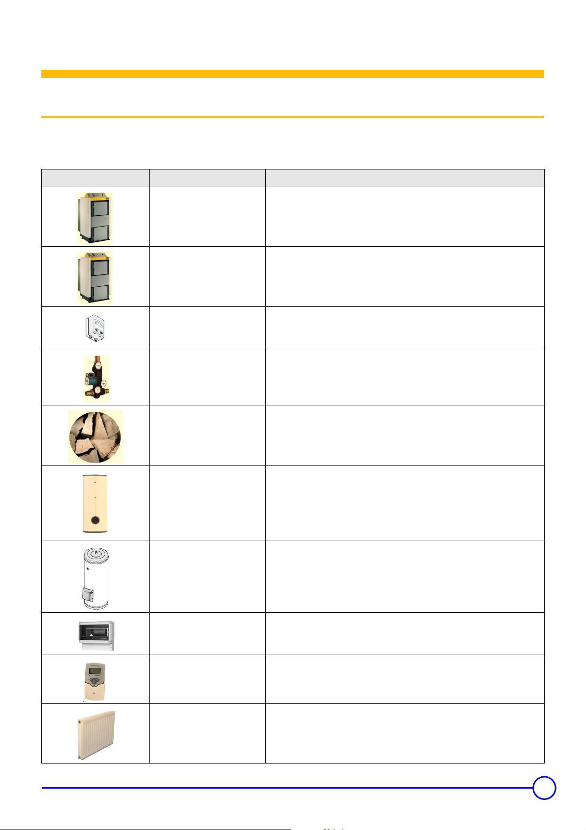
Description Operation
3. Description
CBI-II
Reverse combustion log-fired
boiler
CBB 15 E
Log-fired boiler with natural
draught
EA108
Wall module for elevating the
return temperature
ML9
Thermostatic module for elevating
the return temperature
Logs
Burns wood in complete safety and protects the environment. Removes the heat from
the fumes given off by combustion and transfers it to the heating water.
Burns wood in complete safety and protects the environment. Removes the heat from
the fumes given off by combustion and transfers it to the heating water.
Used to read the return temperature. Stays off if the return temperature is lower than
60°C.
Used to prevent the return of water colder than 60°C into the boiler.
The natural energy of wood is converted into heat by combustion in the Bioenergy
boiler.
Buffer tank
PS / PSB
DC / QUADRO
Domestic hot water tank
LIGHT / DUO / TRIO
8962N094A
DIEMATIC VM
Regulation
Differential regulator Controls the domestic load pump.
Radiators or underfloor heating Transfers the heat from the heating water to the premises.
Used for storing hot water extracted from the biofuel boiler (max. 85°C).
Compensates for any differences between heat production and needs.
Solar use with DC / QUADRO
Maintains a reserve of domestic hot water for the household (e.g. shower) with an
electric back-up for the summer.
Solar use with LIGHT / DUO / TRIO
Optimally ensures the desired temperature on the premises and saves on fuel,
whatever the outside temperature.
16/06/2009 - 300019729-001-C CBI-II / CBB 15 E
5
Page 6

3. Description
Description Operation
DHW pump
Heating pump
Heating water and heating pipes Carries the heat produced in the boiler to the radiators.
Motorised mixing valve
Pressure gauge Indicates the pressure in the heating circuit.
Air vent Ensures that there is no air in the heating pipes.
Safety valve Prevents too great an increase in pressure in the installation.
Circulates the heating water from the boiler to the storage tank and from the storage
tank to the radiators and brings it back to the boiler where it is reheated.
Adapts the outlet temperature from the boiler to the radiators in such a way as to
obtain the desired room temperature, whatever the outside temperature. This is done
by mixing the outlet water with the colder heating return water.
Expansion vessel
L33
Safety exchanger control valve
Maintains a constant pressure in the installation and absorbs the water caused by
expansion.
Use to trigger the safety battery which protects the boiler against overheating.
3.2 Safety
- Safety thermostat with manual reset (110 °C)
- Safety battery (delivered from the factory) to be connected to the
cold water by means of a control valve (option L33)
- Safety valve (To be installed by the fitter)
6
CBI-II / CBB 15 E 16/06/2009 - 300019729-001-C
Page 7

3.3 Boiler
3. Description
1. Ash tray door
2. Loading door
3. Control panel
4. Air flap lever
5. Air regulator flap
6. Air regulator flap chain
7. Output modulator: 60-90 °C
8. Safety exchanger (To be connected by the fitter)
9. 95°C limiter thermostat (except CBB 15 E)
10. Sensor tube for the safety exchanger control valve
11. Inspection hatch
12. Extractor fan (except CBB 15 E)
C002258-B
16/06/2009 - 300019729-001-C CBI-II / CBB 15 E
7
Page 8

3. Description
3.4 Control panel
13. General ON 1 / OFF 0 switch
Boiler CBI-II
C002262-A
1716
16. Safety thermostat with manual reset (110 °C)
14. Boiler thermometer
15. Flue gas thermostat for extractor fan
Boiler CBB 15 E
13. General ON 1 / OFF 0 switch (DHW pump)
14. Boiler thermometer
15. Storage tank load pump thermostat (And/or return temperature
elevating) - If connected
17. Boiler thermostat
8
CBI-II / CBB 15 E 16/06/2009 - 300019729-001-C
Page 9

4. Commissioning
4 Commissioning
4.1 Commissioning
Initial commissioning must be done by a qualified
professional.
4.2 Subsequent start-ups by the final user (at least at the beginning of the heating season)
1. Check the water pressure in the installation. Top up with more
water if necessary.
2. Check that the safety thermostat has not triggered. Remove the
safety thermostat hood and press the reset button with a
screwdriver - except CBB 15 E.
3. Carry out the boiler ignition operations (See chapter: Ignition).
4. Set the output modulator to 80°C.
5. Open the air regulator flap by tensing the chain and wait for the
thermometer to reach 80°C.
6. Secure the chain to obtain an opening of 5 mm and mark the link.
7. Turn the boiler thermostat to Max - except CBB 15 E.
8. Check the pumps:
Turn the unlocking screw located at the centre of the pump with
a screwdriver.
Check that the air regulator flap is fully closed if the boiler
reaches 90°C.
16/06/2009 - 300019729-001-C CBI-II / CBB 15 E
9
Page 10

4. Commissioning
4.3 Ignition
1. Turn the flue gas thermostat to 0 (Ignition) - except CBB 15 E.
2. Set the On/Off switch to 1.
3. Pull the lever to open the air flap.
4. Open the loading door.
5. Put some inflammable kindling with some paper on the bottom of
the combustion chamber. Leave a space of 2 to 4 cm between
the logs for the smoke to escape. Put in logs and light.
6. Close the loading door.
4.4 Adding more logs
Only add more logs if the previous load has been consumed to
at least 1/3 of the original volume.
1. Pull the lever to open the air flap.
2. Turn the flue gas thermostat to 0 (Ignition) - except CBB 15 E.
3. Wait for one minute and open the loading door.
4. Add logs to the combustion chamber.
5. Close the loading door.
7. When the wood is well lit (about 20-30 minutes later), continue to
fill the combustion chamber.
Close the loading door.
8. Push the lever to close the air flap.
9. Set the flue gas thermostat between Min and Max (when in
operation)*. The fan must continue to turn.
* except CBB 15 E.
When the fuel has been consumed, the fan is stopped by the
flue gas thermostat. This makes it possible to keep the embers
burning longer.
6. Push the lever to close the air flap.
Set the flue gas thermostat between Min and Max (when in
operation) - except CBB 15 E.
10
CBI-II / CBB 15 E 16/06/2009 - 300019729-001-C
Page 11

5 Cleaning and regular servicing
CBI-II-20, 30, 40
5. Cleaning and regular servicing
Remove ashes from the boiler every 3 to 7 days depending
on the quality and quantity of wood used.
Clean the flue gas collector and the fan around 1 time per
month.
5.1 Cleaning the boiler (Every 3 to 7 days)
1 3 5
MIN
MAX
0
At the end of the heating season, have the boiler
thoroughly cleaned by a qualified professional.
3
5
2
4
1. Turn the flue gas thermostat to 0 (Ignition) - except CBB 15 E.
2. Open the loading door.
3. Sweep the ashes through the smoke evacuation slit.
5.2 Maximum quantity of ashes
CBB 15 E
Turn the boiler off before cleaning.
See chapter: Stopping the boiler
4
C002322-A
4. Open the ashtray door. Remove ashes and soot using the
ashtray and a scraper.
5. Clean the area around the ceramic combustion chamber
Do not remove the refractory components during cleaning.
1
2
100
3
M000351
2. Combustion chamber
3. Maximum quantity of ashes
4. Baffle
16/06/2009 - 300019729-001-C CBI-II / CBB 15 E
11
Page 12
5. Cleaning and regular servicing
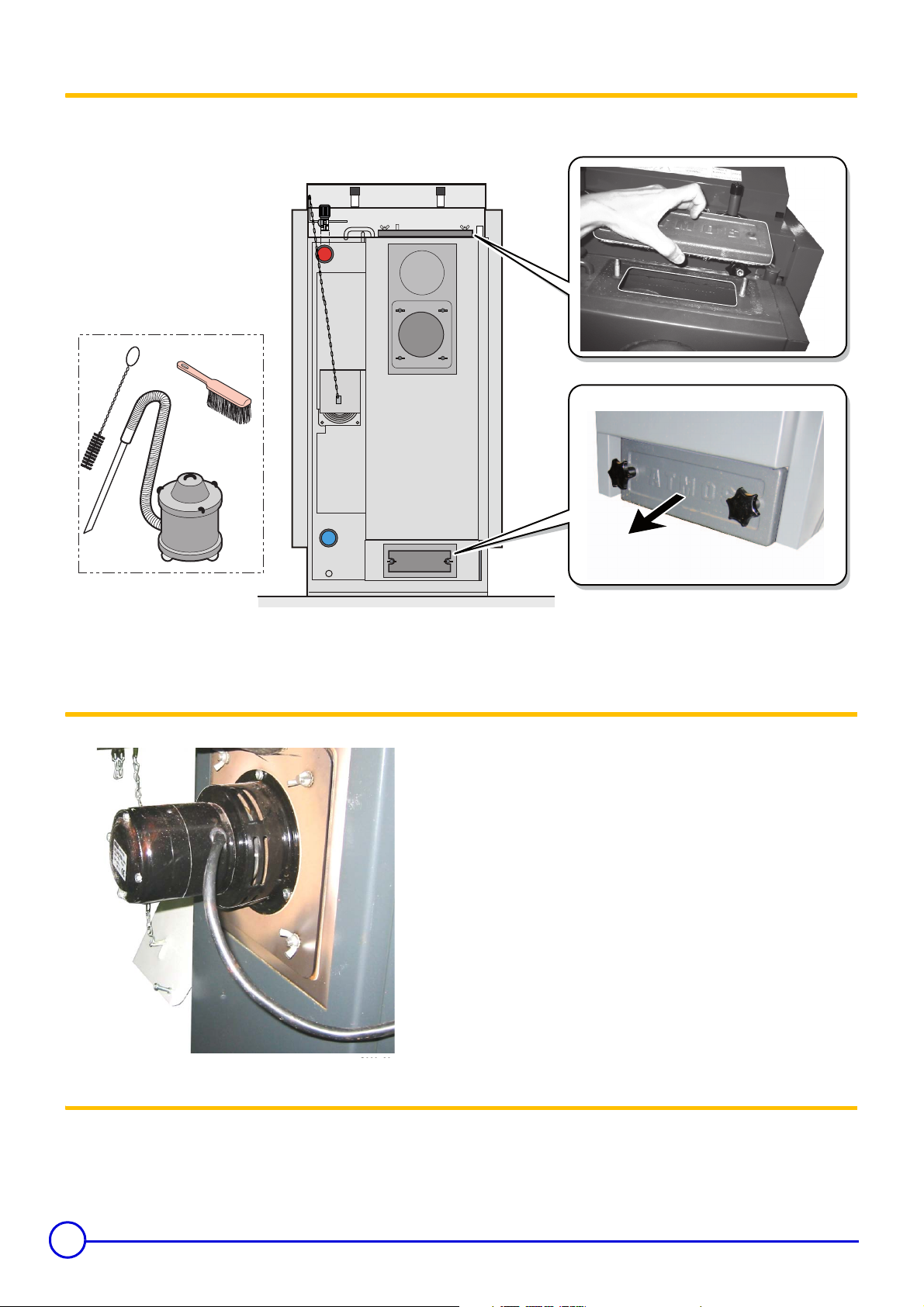
5.3 Cleaning the flue gas collector (Around 1 time per month)
Only on cold boiler.
C002260-C
Open the inspection hatches and clean with a brush. Remove the
ashes via the bottom inspection hatch.
5.4 Cleaning the extractor fan* (Around 1 time per month)
*except CBB 15 E - Remove the extractor fan.
- Clean the vanes.
- Check the squareness of the vanes of the fan.
5.5 Checking the doors (Around 1 time per month)
Check the seal on the boiler doors 1 time per month.
Have the fitter replace the seals if necessary.
12
CBI-II / CBB 15 E 16/06/2009 - 300019729-001-C
Page 13

6 Stopping the boiler
1. Wait until the logs have stopped burning (Wait 3-4 hours).
2. Set the On/Off switch to 0.
6. Stopping the boiler
Specific precautions
Outside the heating period:
- Turn on the circulating pumps at least 1 time per month for 2
minutes.
Precautions to take if there is a danger of frost
Heating circuit:
Use a correctly dosed antifreeze to prevent the heating water
freezing. If this cannot be done, drain the system completely. In all
cases, consult the fitter.
Precautions to take in the event of prolonged shutdown (one year or more)
- The boiler and the chimney must be swept carefully.
- Close the door of the boiler to prevent the internal circulation of air.
- Thoroughly clean the heating surfaces in the boiler.
Domestic hot water circuit:
Drain the domestic water tank and pipes.
16/06/2009 - 300019729-001-C CBI-II / CBB 15 E
13
Page 14

7. Troubleshooting
7 Troubleshooting
Checks to make before calling your fitter:
Faults Probable causes Fault finding
The fire has not properly taken (the set
The boiler stops soon after ignition.
The fan often comes on while the
boiler is operating.
The extractor fan does not work.
Flue gases are escaping from the
loading door.
The radiators are cold.
There is no domestic hot water.
temperature has not been reached). The flue
gas thermostat has turned the boiler off.
The boiler thermostat is set too low. Increase the boiler thermostat setting.
The storage tank load pump does not work.
The thermostats are set incorrectly.
The boiler is not switched on. Turn the boiler on.
The extractor fan is clogged.
The door seals are not airtight.
The heating outlet and return valves are closed. Open valves.
Boiler fitted with a control unit:
The control unit is not correctly set.
The boiler thermostat and/or the remote control
are not correctly set.
The water level and/or pressure are too low. Fill the installation and bleed the radiators.
The radiator valves are closed. Open valves.
The heating circulator pump and/or the storage
tank load pump do not work.
The 3-way valve does not open automatically.
The domestic hot water calorifier load pump
does not work.
There is air in the primary circuit (exchanger)
on the domestic hot water calorifer.
Relight the fire.
See chapter: Ignition
Turn the unlocking screw located at the centre of the pump with a
screwdriver. If the pump still does not work, contact the fitter.
Adjust the thermostats.
See chapter: Commissioning
Clean the extractor fan.
See chapter: Cleaning the flue gas collector (Around 1 time per
month).
Get the fitter to adjust the doors.
Have the fitter replace the seals if necessary.
Check the settings
See: Control unit instructions
Increase the setting.
Turn the unlocking screw located at the centre of the pump with a
screwdriver.
Open the valve.
Contact the fitter.
Turn the unlocking screw located at the centre of the pump with a
screwdriver.
Activate the automatic bleed on the domestic hot water calorifier.
For all other problems: Contact the fitter.
Before informing the fitter of a fault, make a note of the following
information:
- Product type
- Year of manufacture
- Serial number
This information can be found on the rating plate stuck to the side
panel of the boiler.
14
CBI-II / CBB 15 E 16/06/2009 - 300019729-001-C
Page 15

Warranty
7. Troubleshooting
You have just purchased one of our appliances and we thank you
for the trust you have placed in our products.
Please note that your appliance will provide good service for a
longer period of time if it is regularly checked and maintained.
Your fitter and our customer support network are at your disposal
at all times.
Warranty terms
Starting from the purchase date shown on the original fitter's
invoice, your appliance has a contractual guarantee against any
manufacturing defect.
The length of the guarantee is mentioned in the price catalogue.
The manufacturer is not liable for any improper use of the appliance
or failure to maintain or install the unit correctly (the user shall take
care to ensure that the system is installed by a qualified fitter).
In particular, the manufacturer shall not be held responsible for any
damage, loss or injury caused by installations which do not comply
with the following:
- applicable local laws and regulations
- specific requirements relating to the installation, such as national
and/or local regulations
- the manufacturer's instructions, in particular those relating to the
regular maintenance of the unit
- the rules of the profession
Our liability as manufacturer may not be invoked in respect of
incorrect use of the appliance, incorrect or insufficient maintenance
thereof, or incorrect installation of the appliance (you must
therefore ensure that installation and maintenance operations are
carried out respectively by a qualified professional and by an after
sales service company).
The legislation laid down by European Directive 99/44/EEC,
transposed by Legislative Decree No. 24 of 2 February 2002
published in O.J. No. 57 of 8 March 2002, continues to apply.
Switzerland
The application of the warranty is subject to the terms and
conditions of sale, delivery and warranty of the company marketing
our products.
Poland
Warranty conditions are included in the warranty card.
Other countries
The above provisions do not restrict the benefit of the legal laws
regarding hidden defects applicable in the buyer's country.
The warranty is limited to the exchange or repair of such parts as
have been recognised to be faulty by our technical department and
does not cover labour, travel and carriage costs.
The warranty shall not apply to the replacement or repair of parts
damaged by normal wear and tear, negligence, repairs by
unqualified parties, faulty or insufficient monitoring and
maintenance, faulty power supply or the use of unsuitable fuel.
Sub-assemblies such as motors, pumps, electric valves etc. are
guaranteed only if they have never been dismantled.
France
The preceding dispositions are not exclusive of benefits for the
purchaser of the legal guarantee as stated in Civil Code articles
1641 to 1648.
Belgium
The preceding dispositions about the contractual guarantee are not
exclusive of profit if the need arises for the purchaser in Belgium of
the applicable legal dispositions on hidden defects.
Italy
The duration of our warranty is shown on the certificate delivered
with the appliance.
16/06/2009 - 300019729-001-C CBI-II / CBB 15 E
15
Page 16

FR
DE DIETRICH THERMIQUE S.A.S.
www.dedietrich-thermique.fr
Direction des Ven tes France
57, rue de la Gare
F- 67580 MERTZWILLER
+33 (0)3 88 80 27 00
+33 (0)3 88 80 27 99
DE
BE
CN
DE DIETRICH REMEHA GmbH
www.dedietrich-remeha.de
Rheiner Strasse 151
D- 48282 EMSDETTEN
+49 (0)25 72 / 23-5
+49 (0)25 72 / 23-102
info@dedietrich.de
VAN MARCKE
www.vanmarcke.be
Weggevoerdenlaan 5
B- 8500 KORTRIJK
+32 (0)56/23 75 11
DE DIETRICH
www.dedietrich-heating.com
Room 512, Tower A, Kelun Building
12A Guanghua Rd, Chaoyang District
C-100020 BEIJING
+86 (0)106.581.4017
+86 (0)106.581.4018
+86 (0)106.581.7056
+86 (0)106.581.4019
contactBJ@dedietrich.com.cn
LU
RU
AT
NEUBERG S.A.
www.dedietrich-heating.com
39 rue Jacques Stas
L- 2010 LUXEMBOURG
+352 (0)2 401 401
DE DIETRICH
www.dedietrich-otoplenie.ru
Россия
109044 г. Москва
ул. Крутицкий Вал, д. 3
корп. 2, оф. 35
+7 495 988-43-04
+7 495 988-43-04
dedietrich@nnt.ru
ÖAG AG
www.oeag.at
Schemmerlstrasse 66-70
A-1110 WIEN
+43 (0)50406 - 61624
+43 (0)50406 - 61569
dedietrich@oeag.at
CH
WALTER MEIER (Klima Schweiz) AG
www.waltermeier.com
Bahnstrasse 24
CH-8603 SCHWERZENBACH
+41 (0) 44 806 44 24
Serviceline +41 (0)8 00 846 846
+41 (0) 44 806 44 25
ch.klima@waltermeier.com
WALTER MEIER (Climat Suisse) SA
www.waltermeier.com
Z.I. de la Veyre B, St-Légier
CH-1800 VEVEY 1
+41 (0) 21 943 02 22
Serviceline +41 (0)8 00 846 846
+41 (0) 21 943 02 33
ch.climat@waltermeier.com
© Copyright
All technical and technological information contained in these technical instructions, as well as any
drawings and technical descriptions supplied, remain our property and shall not be multiplied
without our prior consent in writing.
Subject to alterations.
16/06/2009
AD001NU-AB
DE DIETRICH THERMIQUE
57, rue de la Gare F- 67580 MERTZWILLER - BP 30
 Loading...