

DeDietrich C230 ECO-A 120, C230 ECO-A 160, C230 ECO-A 200 Installation, Operating And Service Manual
ENG
10/2012
De Dietrich C230 ECO-A Series
Gas-Fired Condensing Hot Water Boiler
Models
C230 ECO-A 80
C230 ECO-A 120
C230 ECO-A 160
C230 ECO-A 200
Installation,
Operating and
service manual
Important
This is a category II or IV boiler,
only use an approved type ‘BH’
vent or equivalent, consult the
venting section in this manual.
Warning: Before you operate this boiler, read this manual carefully and take extra precautions to all safety
and warning symbols or important items. The installation and service manual is part of the documentation
along with the boiler. The installer is required to explain your heating system and boiler operating
instructions.
Notice: Please read this manual and retain for future reference. Improper installation, adjustment, alteration,
service or maintenance can cause injury, loss of life or property damage. Refer to this manual for assistance
or additional information or consult a qualified installer, service agency or the gas supplier.


Table of contents C230 ECO-A
3
Table of contents
Preface 7
1 Introduction 8
1.1 Pictograms used 8
1.2 Important instructions 8
2 Safety 9
3 Boiler description 10
3.1 General description 10
3.2 Boiler layout 11
3.3 Operating principle 12
3.4 Boiler Control 12
3.4.1 Temperature control 12
3.4.2 Low water level protection 12
3.4.3 Maximum protection 13
3.4.4 Frost protection 13
4 Installation 14
4.1 Standards and certifications 14
4.2 Regulations governing installation 14
4.3 Scope of delivery and installation 15
4.4 Installation and service clearances 17
5 Water-side connections 19
5.1.1 Flue gas condensation discharge 19
5.1.2 Water treatment 19
5.1.3 Circulation pump 20
5.1.4 Water flow 20
5.1.5 Water pressure 20
5.1.6 Safety relief valve 21
5.1.7 Water system layout 21
6 Gas-side connections 23
6.1 Gas connection 23
6.2 Gas pressure 23
6.3 Gas/air ratio control 24
7 Flue gas discharge and air supply 25
7.1 General 25
7.1.1 Boiler Venting Types 25
7.1.2 Venting options 26
7.1.3 Vent Termination Inlet/Outlets 26
7.1.4 Combustion Air Supply Requirements 26
7.1.5 Conventional Chimney Venting & CLV system Application Requirements 27
7.1.6 Direct Vent-Sealed Combustion Application 31
7.1.7 Co-venting – Retrofitting 34
7.1.8 Vent terminations installation precautions 34
8 Control and electrical connections 36
8.1 General 36
8.1.1 Boiler control 36
8.1.2 Modulating controls general 37
8.1.3 Modulating room control 37

8.2 Wiring diagrams 38
8.3 Electrical specifications 40
8.3.1 Mains voltage 40
8.3.2 Control box 40
8.3.3 Fuse ratings 40
8.4 Electrical connection options 41
8.4.1 Connection options of standard control unit (PCU-01) 41
8.4.2 On/off control (OT) 41
8.4.3 Modulating controls (OT) 41
8.4.4 External interlock (BL) 41
8.4.5 Input release (RL) 42
8.4.6 Circulation pump (Pump) 42
8.5 Connection options for the optional 0 - 10 V control PCB (IF-01) 42
8.5.1 Connection status (Nc) 42
8.5.2 OTm connection 42
8.5.3 Analogue input (0 - 10 V) 43
8.5.4 Analogue input (0 - 10 V) 44
8.6 Connection options for the optional 0 - 20 mA control PCB 45
8.6.1 Connection status (Nc) 45
8.6.2 OTm connection 45
8.6.3 Analogue input (0 - 20 mA) 45
8.6.4 Analogue input (0 - 20 mA) 46
8.7 Connection options of the optional expanded control/protection PCB (SCU-S01) 47
8.7.1 Flue gas damper control (FgV) 47
8.7.2 Hydraulic valve control (HdV) 47
8.7.3 External gas valve control (EgV) 47
8.7.4 Operation signal and failure signal (Nc / No) 47
8.7.5 Water pressure sensor (Wps) 47
8.7.6 Outside temperature sensor (Tout) 48
8.7.7 Minimum gas pressure switch (Gps) 48
8.7.8 Gas leakage control (VPS; only for 230- 160 and 230- 200 boilers) 48
9 Commissioning 49
9.1 Control panel 49
9.1.1 Normal start-up procedure 49
9.1.2 Fault during start-up procedure 50
9.1.3 Reading current values 51
9.1.4 Adjusting the boiler to the system 52
9.1.5 Changing parameters at user level (without access code) 53
9.1.6 Changing parameters at service level (with access code) 53
9.1.7 Resetting factory settings 56
9.1.8 Setting manual operation ( symbol) 57
9.2 Commissioning 57
9.3 Taking the boiler out of operation 60
9.3.1 Boiler with frost protection, out of operation for a long time 60
9.3.2 Boiler without frost protection, out of operation for a long time 60
10 Inspection and maintenance 62
10.1 General 62
10.2 Combustion check of the boiler 62
10.2.1 Corrective maintenance 63
10.2.2 Cleaning the fan 63
10.2.3 Cleaning the heat exchanger (flue gas side) 65
10.2.4 Cleaning the burner 66
10.3 Cleaning the trap 66
10.4 Checking the ignition electrode 66
10.5 Checking for leaks 67
10.6 Checking water pressure 67
10.7 Putting boiler back into operation 67
4

Table of contents C230 ECO-A
11 Control stops and faults 68
11.1 General 68
11.2 Control stops and faults 68
11.3 Control stop codes 68
11.4 Fault codes 71
11.5 Control stop - and fault memory 74
11.5.1 Reading faults 75
11.5.2 Deleting control stops or faults 76
12 Service parts 77
12.1 General 77
12.2 Exploded views 78
13 Technical specifications 83
13.1 Technical data 83
14 Efficiency information 84
14.1 Unit usable efficiency (HR efficiency) 84
14.2 Water-side efficiency 84
14.3 Zero-load losses 84
15 General information 85
15.1 Description of specifications 85
15.2 Accessories 85
15.3 Services 86
16 Application data 87
16.1 General 87
16.2 Air and flue gas application options 87
16.3 Hydraulic application options 87
16.4 Control options 87
16.5 Gas application options 87
17 Checklists (records) 88
17.1 Checklist for commissioning (Commissioning record) 88
17.2 Checklist for annual inspection (inspection record) 88
17.3 Checklist for maintenance (maintenance record) 89
5


Preface C230 ECO-A
Preface
This installation and service manual, which contains a lot of practical
information about the De Dietrich C230 ECO-A, a High efficiency
central heating unit, is mainly intended for installers. It contains
important instructions for safe and trouble-free operation of the boiler
before commissioning and during operation.
Read these instructions carefully before putting the boiler into
operation, familiarize yourself with its control functions, operation and
strictly observe the instructions given. Failure to do so may invalidate
warranty or prevent the boiler from operating. The following boiler
models are available:
C230 ECO-A 80 (3 sections; 297 MBH (87 kW))
C230 ECO-A 120 (4 sections; 359 MBH (105 kW))
C230 ECO-A 160 (5 sections; 567 MBH (166 kW))
C230 ECO-A 200 (6 sections; 683 MBH (200 kW))
Installation and any service, maintenance or reparation of this product
may only be done by a licensed heating technician, trained in and
experienced with hot water boiler installation and gas combustion. The
product must be installed according to all national and local codes
having jurisdiction. Canadian installation must conform to CSA B149 &
US installation ANSI Z223.1.
If you have any questions, need more information or require an
engineer to call on site, please contact our technical help line
1.800.943.6275 Monday thru Friday 08:00 - 17:00 EST.
When contacting De Dietrich America's with a problem on the boiler,
please provide the following information: the boiler type, Serial No
(located on the bottom of the casing), and the symptoms or fault code
(the fault code is a series of flashing digits in the display panel).
The data published in this manual is based on the latest information
(at date of publication) and may be subject to revisions.
We reserve the right to continuous development in both design and
manufacture, therefore any changes to the materials or technology
employed may not be retrospective nor may we be obliged to adjust
earlier supplies accordingly.
7
1 Introduction C230 ECO-A
1 Introduction
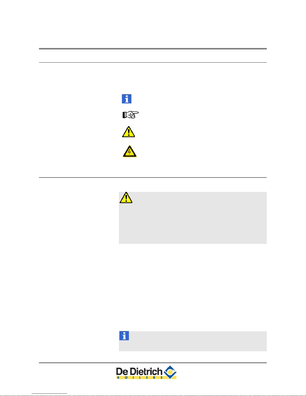
1.1 Pictograms used
The following pictograms are used in this document to emphasize
certain instructions. This is in order to increase your personal safety
and to safeguard the technical reliability of the boiler. The pictograms
used are:
Useful advice.
Important instruction for carrying out an action.
Possible risk of personal injury or material damage
to boiler, building or environment.
Possible risk of electrical shocks. Serious personal
injury may occur.
1.2 Important instructions
The boiler must be installed in a frost-free area.
Work on the boiler
Installation, commissioning, maintenance and repair work may only be
carried out by suitably qualified specialist installers in accordance with
the applicable national and local standards and guidelines. Always
disconnect the mains supply and close the main gas cock when
working on the boiler. Check the entire system for leaks after
maintenance and servicing work.
Casing panels may only be removed for maintenance and servicing
purposes. Refit all panels on completion of maintenance and servicing
work.
Instructions and warning labels on the boiler must never be
removed or covered and must be clearly legible throughout the entire
service life of the boiler. Replace damaged or illegible instruction and
warning labels immediately. Generally applicable safety instructions
related to accident prevention must be consulted in addition to the
information supplied in this manual.
Boiler modifications and spare parts
The boiler must not be modified or non OEM spare parts fitted without
the written approval of De Dietrich Boilers.
Keep this document near the boiler.
8
C230 ECO-A 2 Safety
2 Safety
Adhere strictly to the specific safety instructions.
Can you smell gas? Proceed as follows:
Do not smoke and avoid fire and sparks.
Do not operate electrical switches.
Close the gas cock.
Open doors and windows.
Warn those present and leave the building together.
Do not use any phone in the building.
Call your gas supplier once your outside the building. If you
cannot reach them, call the fire department.
Can you smell flue or combustion gases? Proceed as follows:
Isolate the mains power supply from the boiler.
Open doors and windows.
Trace possible leaks and seal them off.
Do not use the boiler, if any part has been under water
Immediately call your service company to inspect the boiler and
replace any part of the control or gas controls.
The boiler casing is not designed for supporting other items, damage
to the casing will result if used for supporting or suspending items. Do
not walk or use the boiler casing as a ladder.
9

3 Boiler description C230 ECO-A
3 Boiler description
3.1 General description
The De Dietrich C230 ECO-A is a pre-assembled, free standing, gas
fired, high efficiency condensing boiler. The sectional cast aluminium
heat exchanger and other major components are contained within a
sealed air box. This forms the main boiler casing with a removable
inspection hatch for maintenance purposes. All electrical and
electronic controls are contained within the instrument panel mounted
on top of the boiler.
The flue gas outlet, combustion air inlet, flow, return and gas
connections are located on top of the boiler with a condensate
connection at low level on the right hand side.
The boiler is suitable for room sealed or open flue applications and
has been designed for central heating and indirect hot water
production at working pressures not exceeding 100 psi (7 bar). It must
be installed on a fully pumped system and is suitable for use on
sealed installations.
The premix gas burner with its gas/air ration control system ensures
clean, trouble free operation with higher than average efficiencies
109% (NCV) in the condensing mode combined with ultra low NO
x
and minimum CO emissions. The standard control package allows
actual and set values to be read and adjusted on the built-in digital
display which also provides normal operating and fault code
indication.
An intelligent, advanced boiler control (Comfort Master) continuously
monitors the boiler conditions, varying the heat output to suit the
system load. The control is able to react to external “negative”
influences in the rest of the system (flow rates, gas/air supply
problems) maintaining boiler output for as long as possible without
resorting to a lockout condition. At worst the boiler will reduce its
output and/or shutdown (shut off mode) awaiting the “negative"
conditions to return to normal before restarting.
The Comfort Master control cannot override the standard flame safety
controls.
10
C230 ECO-A 3 Boiler description
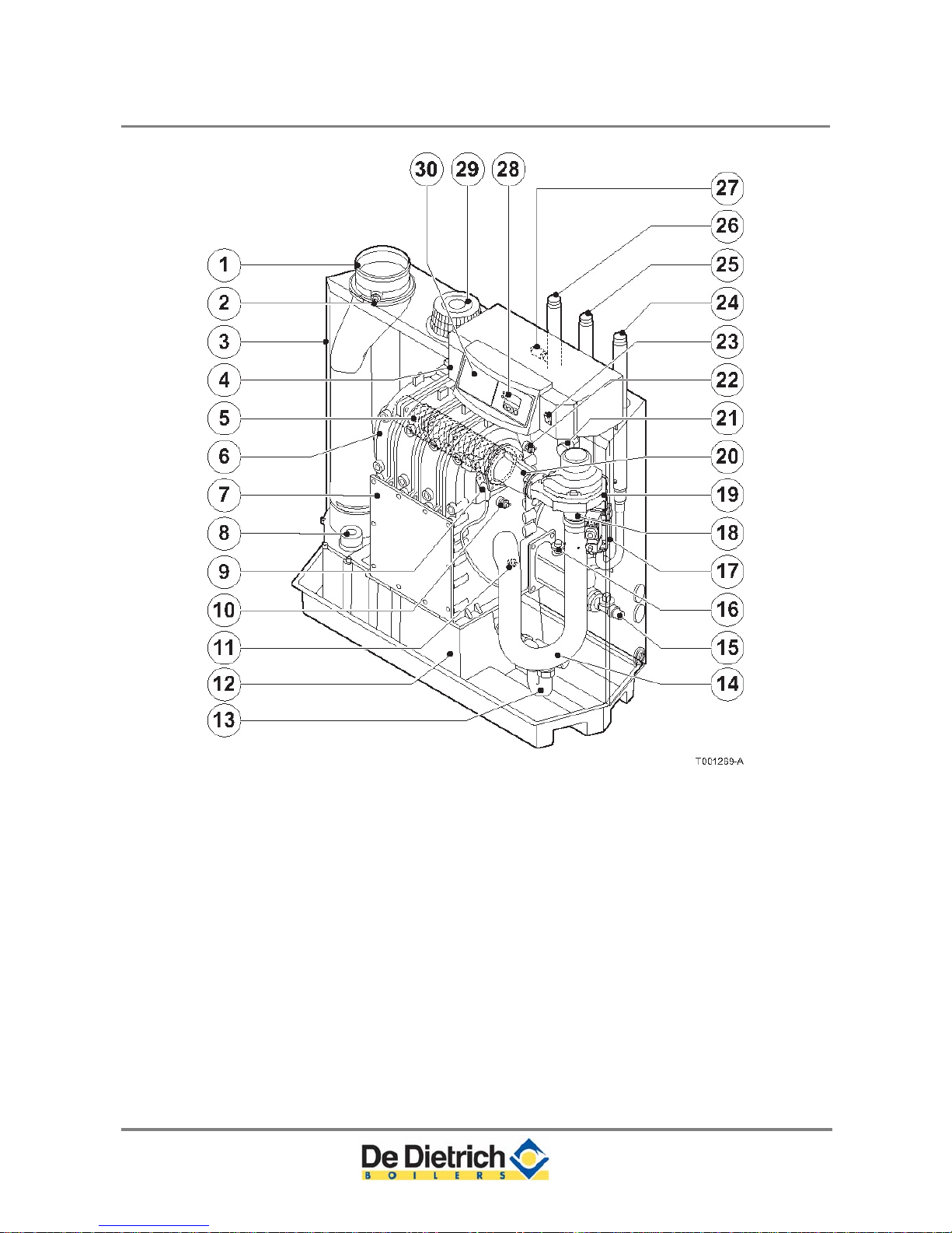
3.2 Boiler layout
Fig. 1 Cross-section
1. Flue gas discharge 11. Return temperature sensor 21. Flue gas switch
2. O2/CO2 measuring point
12. Condensate collector 22. Flow temperature sensor
3. Air box 13. Condensate trap 23. On/off
4. Control panel 14. Air silencing tube 24. Gas connection
5. Burner 15. Filling and drain cock 25. Return connection
6. Heat exchanger 16. Water pressure switch (option) 26. Flow connection
7. Inspection hatch 17. Gas multiblock 27. Thermostat pocket
8. Inspection hatch for condensate
collector
18. Venturi 28. Display
9.Ignition pin 19. Fan 29. Combustion air supply
10. Boiler heath exchanger sensor 20.Mixing tube
30. Facility for built-in weather
compensator
11

3 Boiler description C230 ECO-A
3.3 Operating principle
Combustion air is drawn into the closed air box through the air inlet
from the plant room (open flued) or from outside via the eccentric flue
system (room sealed) by the boiler gas/air supply fan.
Depending on demand (under the dictates of flow/return sensor and
other external/internal control inputs), the Comfort Master system
determines the boiler output, which directly controls the volume of
mixed gas and air to the premix burner. This mixture is initially ignited
by the combined ignitions & ionization probe, which monitors the state
of the flame. Should the flame be unstable or not ignite within the preset safety time cycle, the controls will shut the boiler down requiring
manual intervention to reset the boiler. The digital display will indicate
a flashing fault code confirming the reason for the failure.
The products of combustion in the form of hot flue gases are forced
through the heat exchanger transferring their heat to the system water
(the flue gas temperature is reduced to approximately 9
°F (5 °C)
above the temperature of the system return water). Then they are discharged
via the condensate collector, vertically through the 5.9” (150 mm) flue gas
connection to the atmosphere.
Because of the low flue gas exit temperature there will be a vapor cloud
formed at the flue gas terminal - this is not smoke, simply water vapor formed
during the combustion process.
If the controls allow the flow and therefore return temperature to fall below
dew point (131 °F (55 °C)) this water vapor will begin to condense out in the
boiler, transferring its latent heat into the system water, increasing the output
of the boiler without increasing the gas consumption. Condensation formed
within the boiler and flue system is discharged from the boiler to an external
drain via the drain pan/siphon supplied.
3.4 Boiler Control
3.4.1 Temperature control
The C230 ECO-A is equipped with electronic temperature control
based on flow, return and boiler block temperature sensors. The flow
temperature is adjustable between 68 and 194°F (20 and 90°C)
(factory setting 176°F (80°C)).
3.4.2 Low water level protection
The C230 ECO-A is equipped with low water protection based on
temperature difference measurements and temperature increase
measurements. In some jurisdictions this internal function may not be
acceptable, a separate low water cut-off (LWCO) safety device will be
needed.
This function safeguards the boiler only, a separate control is needed
for the system.
12

C230 ECO-A 3 Boiler description
3.4.3 Maximum protection
The maximum protection switches the unit off if the water temperature
is too high (230°F (110°C)) and interlocks it on the control box. Once
the fault has been remedied, the unit can be reset using the reset-
key.
3.4.4 Frost protection
The unit must be installed in a frost-free area to prevent freezing of
the condensate drain pipe. If the temperature of the heating water
drops too much, the built-in unit protection activates.
13

4 Installation C230 ECO-A
4 Installation
4.1 Standards and certifications
Installation, commissioning, maintenance and repair work must
only be carried out by a suitably qualified specialist.
Installations must conform to national and local codes having
jurisdiction. Canadian installation must conform to CSA B149 &
US installation ANSI Z223.1.
The Gas 230 ECO-A boiler or any of its components do not contain
crystalline silica.
The boiler is certified to use natural gas only with a gas supply of
< 0.5 psig or a gas supply pressure range of 7-14” w.c. [17-35
mbar] max.
The Gas 230 ECO-A boilers are certified with the burner control
unit Comfort Master. Consult local codes having ju
risdiction for
other requirements.
All installation must provid
e a fitted safety relief valve on the boiler
supply piping, without any obstructions or valves. The safety relief
valve needs to be piped to a nearby drain that will avoid personal
injury or damage to property. The relief valve must be sized
according to the minimum relief capacity as listed on the boiler
nameplate. Consult local or national code having jurisdictions
regarding the relief valve piping arrangement.
The condensate is very aggressive and can be harmful to some
drain systems, neutralization of the condensate may be
necessary, consult local codes.
The boiler requires an adequate supply of combustion air, unless
the boiler is a sealed combustion system. The boiler needs a
clean combustion air source according to CSA B149 & ANSI Z223
gas codes.
4.2 Regulations governing installation
Installation and maintenance must be done by a qualified
professional, in compliance with prevailing local and national
regulations.
Gas Installation Code CSA B 149 & ANSI Z223.1 (NFPA 54)
In addition to the above regulations, this boiler must be installed in
compliance with:
National & local building codes
ASME CSD-1 as required
CSA & NEC electrical codes
Other Regulations
The C230 ECO-A is a CSA certified boiler and must not be modified or
installed in any way contrary to this Installation manual.
Manufacturer’s Instructions must NOT be taken as overriding statutory
obligations.
14
C230 ECO-A 4 Installation
4.3 Scope of delivery and installation
The boiler is supplied fully assembled and protected. The boiler is
placed on a pallet ( 28" (70 cm) x 51" (130 cm) x 57" (145 cm)), which
can be transported with a pallet truck, hand truck, forklift truck or 4wheel transport boards. The packaging passes through all standard
doors (minimum width of 29" (74.5 cm)).
The boiler is installed as follows:
Position the pallet with the boiler in the boiler room;
Remove the fixing bands and all other packaging (some
components are packaged in the polystyrene cap);
Lift the boiler from the pallet;
Slide the boiler into the required position, using the recessed
handles in the boiler base;
Cover the boiler and do not operate it while dust creating
construction processes or insulation to the pipe work etc. are
carried out in the plant room.
Install the boiler such that the gas ignition system components are
protected from water (dripping, spraying, rain, etc.) during
operation and service.
Do not install the boiler on carpet or other combustible materials.
Do not install the boiler near combustible constructions, vent
connector, and steam and hot-water pipes.
15
4 Installation C230 ECO-A
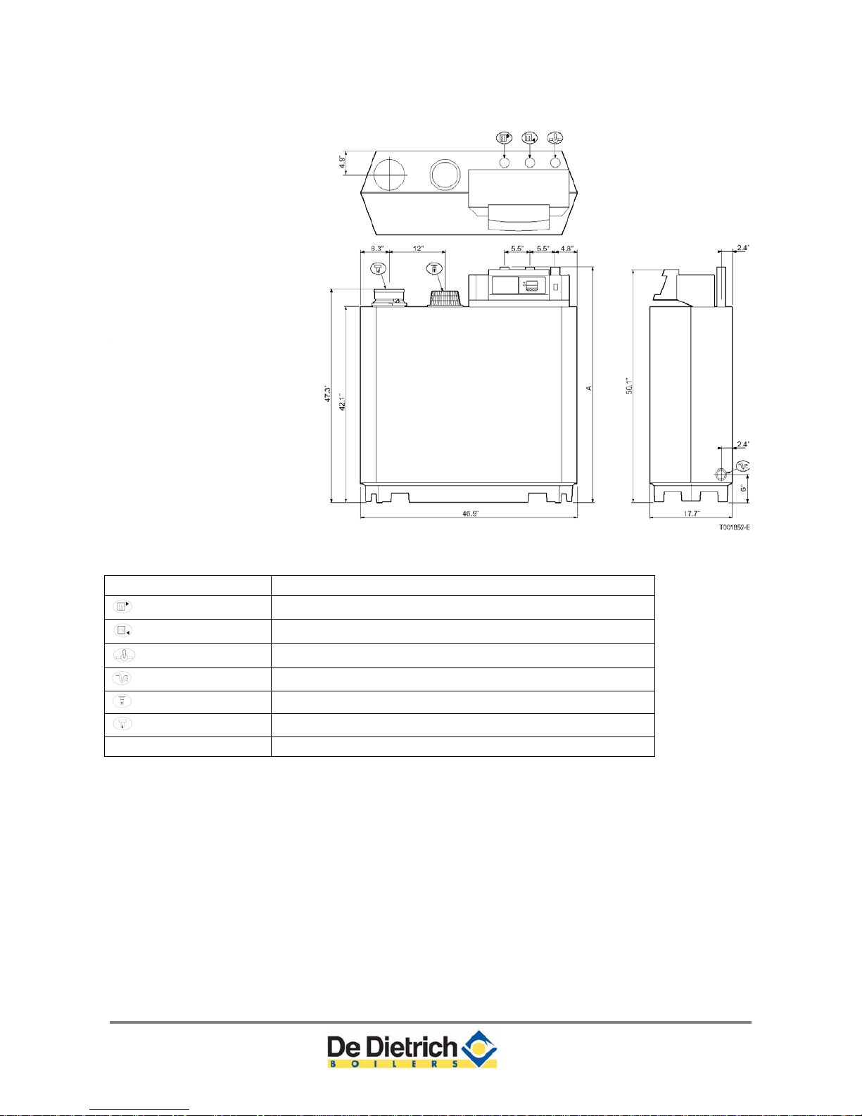
Dimensions
Fig. 2 Elevation drawings
Connection C230 ECO-A 80/120/160/200
Flow
2” NPT thread (do not remove the adapter, pipe is non-NPT)
Return
2” NPT thread (do not remove the adapter, pipe is non-NPT)
Gas connection
2” NPT thread (do not remove the adapter, pipe is non-NPT)
Condensate drain
1.26" (32 mm) external
Combustion air supply
5.91" (150 mm)
Flue gas outlet
5.91" (150 mm)
Dimension “A”
52½” (1330 mm)
16
C230 Eco-A 4 Installation
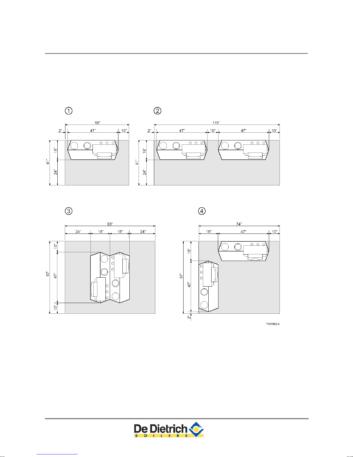
4.4 Installation and service clearances
Clearance of at least 24" (600 mm) is required at the front of the
boiler. However, we recommend a clearance of 40" (1 m). We
recommend a clearance of at least 16" (400 mm) above the boiler
control panel, at least 2" (50 mm) on the left side and at least 10" (25
cm) on the right side in connection with condensed water discharge.
Install a gas cock in the immediate vicinity of/above the boiler.
17
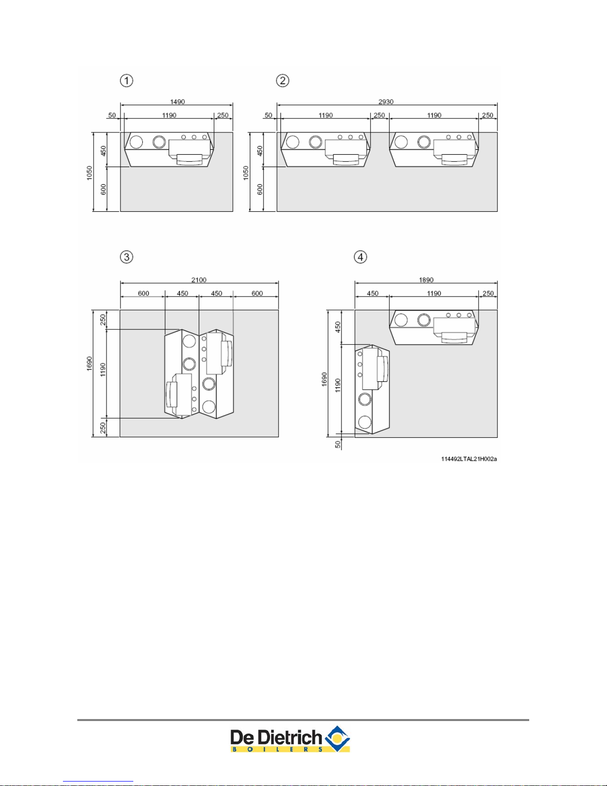
4 Installation C230 ECO-A
Fig. 3 Boiler room installation options (in inches and mm)
18
C230 ECO-A 5 Water-side connections
5 W ater-side connections
5.1.1 Flue gas condensation discharge
Discharge the condensate water directly into a city water drain. In
view of the acidity level of the condensate (pH between 3 and 5), use
only materials that can resist flue gas condensation for the discharge
pipe. The use of neutralizer shall be considered for older drains or
where local codes require.
After assembly, fill the trap with clean water. Make an open
connection with the drain. The discharge pipe must slope down by at
least 3"/100" (30 mm/m). Condensed water must not be discharged
into gutters or rain water down pipes.
5.1.2 Water treatment
Use untreated tap water only to fill the heating system.
The pH value of the system water must be between 7 and 9.
If water treatment is used, the chemicals used shall comply with
the water quality requirements and must not affect cast aluminium
boilers. Follow the manufacturer’s instructions given.
For further information a special document about water quality
regulations is available from De Dietrich America's. The regulations
mentioned in this document must be followed.
As most systems contain a variety of metals, it is considered good
practice to provide some form of water treatment in order to prevent or
reduce the following:
Metallic corrosion
Formation of scale and sludge
Microbiological contamination
Chemical changes in the untreated system water
All scale or calcium deposits, will reduce the efficiency of the boiler
and should be prevented.
Suitable chemicals and their use should be discussed with a specialist
water treatment company prior to carrying out any work
(environmental aspects, health aspects). The specification of the
system and manufacturers recommendations must be taken into
account, along with the age and condition of the system. New systems
should be flushed thoroughly to remove all traces of flux, debris,
grease and metal swarf generated during installation. Take care with
old systems to ensure any black metallic iron oxide sludge and other
corrosive residues are removed, again by power flushing, ensuring
that the system is drained completely from all low points.
19
5 Water-side connections C230 ECO-A
Please ensure that the new boiler plant is not in circuit when the
flushing takes place, especially if cleansing chemicals are used to
assist the process.
It is important to check the inhibitor concentration after installation,
system modifications, filling the system and every service in
accordance with these instructions.
For the correct dosage and the suitability of inhibitors for use with our
boilers and for further information on water treatment or system
cleaning we advise you to contact a water treatment company who is
experienced with our boilers.
5.1.3 Circulation pump
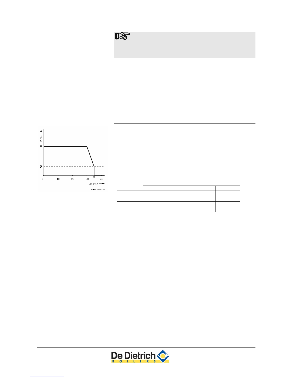
Fig. 4 Output control characteristic
V = full load P = heat output
D = part load ∆T = temperature
difference
The boiler is equipped with a pump switch to connect an
external circulation pump. This pump is run once every 24
hours to prevent sticking (24 hour pump operation).
Only on/off pumps can be controlled. For connections, see
Section 8.4.6.
The hydrauli
c resistance for the various output options of the
boiler is as follows:
Hydraulic resistance
at a dT of 36°F (20°C)
Hydraulic resistance
at a dT of 18°F (10°C)
Boiler
model
mbar psi mbar psi
C230 80
165 2.39 545 7.90
C230 120
135 1.96 446 6.47
C230 160
170 2,47 562 8.15
C230 200
180 2,61 595 8.63
5.1.4 Water flow
The maximum temperature difference between flow and return, and
the maximum rate of rise of the flow temperature and boiler block
temperature are limited by the boiler's modulating controls. As a
result, the boiler is virtually unaffected by low water flow. However for
a continuous supply of heat, the boiler requires a minimum flow of
30% of the nominal flow at the relevant design temperatures.
5.1.5 Water pressure
The boiler is suitable for a maximum working pressure of 100 psi (6.8
bar) according to ASME MWAP = 100 psi. The minimum operating
pressure shall not be less than < 11.6 psi (0.8 bar).
20
C230 ECO-A 5 Water-side connections
5.1.6 Safety relief valve
A safety relief valve NB certified with V or HV & CRN symbols, must
be installed within 20 inches on the boiler supply piping without any
obstructions. The relief valve must not be smaller than 3/4 inch and
not larger than 4 inch. The pressure shall not exceed 10% above the
MAWP and must be of an automatic reset type. The valve opening
must be routed away so that no injury or damage to property will
result. Consult local codes. When replacing the valve, the relief
capacity must be more than the minimum relief capacity shown on the
boiler rating plate.
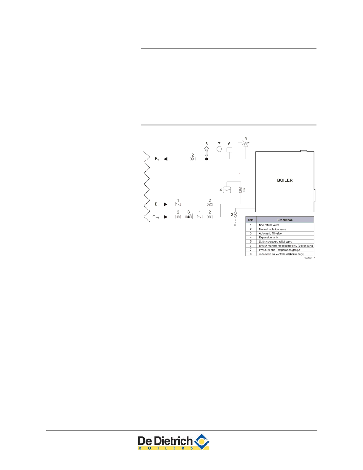
5.1.7 Water system layout
Fig. 5 Boiler water connections (minimum)
The above piping diagram illustrates the minimum boiler system
controls needed, the by-pass system is not necessary, but can be
used in multiple heating temperature circuits.
The boiler if installed above radiation (heating circuits below the
boiler) or as required by local codes or authorities having jurisdiction
must install a low water cut-off safety device, The LWCO is not a
standard scope of supply, but is available as an option. The boiler has
been approved and has found to be in compliance to the LWCO
protection, provided the factory pre-set high limit and flow
temperatures are not altered and the modulating controls are used
and no minimum flow is required as the Comfort master system will
monitor these conditions and reduce the boiler output, finally shutting
down until the flow conditions improve, As a result, the boiler is
virtually unaffected by low water flow. Although boiler flow and content
protection is provided, does not safeguard the entire heating system,
additional low water content and temperature safety control maybe
needed in certain jurisdictions.
21

5 Water-side connections C230 ECO-A
It is strongly recommended that a decoupling device is installed to
isolate the boiler during non working times and/or when the system or
boiler flow is unknown
When the boiler is connected to a refrigeration system, it must be
installed so the chilled medium is piped in parallel with the boiler with
appropriate valves to prevent the chilled medium from entering the
boiler.
The boiler piping system of a hot water boiler connected to heating
coils located in air handling units where they may be exposed to
refrigeration air circulation must be equipped with flow control valves
or other automatic means to prevent gravity circulation of the boiler
water during cooling operations.
22
C230 ECO-A 6 Gas-side connections
6 Gas-side connections
6.1 Gas connection
The boiler is suitable for use with natural gas and propane*. For other
types of natural gas, consult our Technical department. All gas
appliances must, by law, be installed by competent persons. Failure to
install appliances correctly could lead to prosecution.
It is in your own interest and that of safety to ensure that the law is
complied with.
The gas connection is at the top of the boiler. We recommend
installing a gas filter in the gas supply pipe to avoid pollution of the
gas multiblock. The gas filter's resistance must not be so high that the
minimum inlet gas pressure can no longer be achieved.
Gas installation instructions
1.
A main gas shutoff valve should be connected to the boiler within
accessible area and within hand reach.
2. A sedime
nt trap must be installed upstream of the main gas
shutoff valve.
3. The boiler gas train (valve) does not require venting or bleeding, a
VPS can be used in jurisdiction where required.
The boiler and the individual shutoff valve must be leak tested
according to local and national gas installation codes B149 & ANSI
Z223.1. If the leak pressure testing exceeds 1/2 psi (35 mbar) the
boiler and the individual gas shutoff valve shall be isolated and
disconnect during this test.
* OEM gas conversion kit required (optional).
6.2 Gas pressure
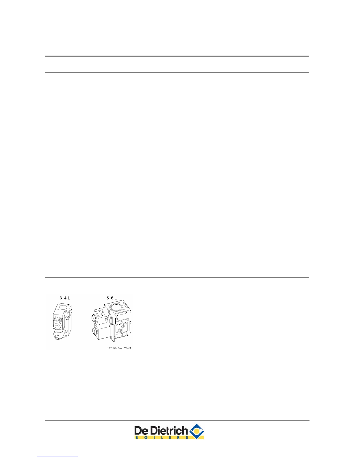
Fig. 6 Gas multiblocks
The boiler has been factory set and tested to natural gas (G20) with an inlet pressure of 7 inches w.c.(17 mbar).
Higher gas supply pressure(s) require a separate service regulator.
Natural gas supply inlet pressure range 3.5 - 14 inches w.c. (< 0.5
psi) [8.7 - 35 mbar) is required.
For propane (LPG), an inlet pressure of 8 - 13 inches w.c. (< 0.5
psi) [20 - 32 mbar) is required.
23

6 Gas-side connections C230 ECO-A
Gas system pressure checks
The boiler main gas cock shutoff valve and piping must be
isolated from any gas piping pressure testing in excess of 0.5 psi
(35 mbar).
The boiler main gas cock shutoff valve and piping must be
isolated by closing the main gas cock shutoff valve during gas
piping pressure testing less than 0.5 psi (35 mbar).
The boiler main gas piping and gas train must be leak tested prior
to placing the boiler in operation.
6.3 Gas/air ratio control
The boiler has a zero governor gas valve. This gas valve maintains
the ratio between the gas and air quantities in the burner at a constant
level under variable loads. This ensures clean and reliable combustion
and high efficiency across the entire load range. There is no need to
vent the gas valve.
24

C230 ECO-A 7 Flue gas discharge and air supply
7 Flue gas discharge and air supply
7.1 General
The C230 ECO-A is suitable for both conventional room-supplied or
sealed combustion. Sealed combustion terminals should comply with
the local and national codes. Any horizontal pipe-work in the flue gas
discharge system should slope towards the boiler. Horizontal pipework in the air supply system should slope towards the supply
opening and may require a drain point at the low point. Care should
be taken when locating flue exit positions as a vapor plume will be
visible when the boiler is operational (flue gas temperature will be less
than 170°F [77°C] resulting in the water vapor condensing out on
contact with the air).
Provisions for combustion and ventilation air in accordance with
section 5.3, Air for Combustion and Ventilation, of the National Fuel
Gas Code, ANSI Z223.1/NFPA 54, or Sections 7.2, 7.3 or 7.4 of the
Natural Gas and Propane Installation Code, CAN/CSA B149.1, or
applicable provisions of the local building codes.
For boilers for connection to gas vents or chimneys, vent installation
shall be in accordance with Part 7, Venting of Equipment, of the
National Fuel Gas Code, ANSI Z223.1/NFPA 54, or Section 7, Venting
Systems and Air Supply for Appliances, of the Natural Gas and
Propane Installation Code, CAN/CSA B149.1, or applicable provisions
of the local building codes.
The venting system shall be installed in accordance with the boiler
manufacturer’s installation instructions.
The horizontal portions of the venting system shall be supported to
prevent sagging. Follow the instructions of the supplier of the venting
system.
7.1.1 Boiler Venting Types
Flue gas venting
Use only an approved gas vent category II and IV type “BH” (AL29-4C
stainless steel vent material). Plastic vent material (CPVC/PVC) can
be used where local/national codes allow.
Conventional Chimney Applications
A vertical chi
mney-vent system with the air supply, required for
combustion, provided within the boiler room or combustion air sour
ce
provided into the room.
CLV – Direct Vent (Sealed Combustion) Systems Applications
Vertical o
r horizontal venting systems for both, the flue gases and
combustion ai
r operating at two different pressure zones or vent
terminal locations.
25
7 Flue gas discharge and air supply C230 ECO-A
Sidewall Vented & Direct Vent [Sealed Combustion] Applications
A horizontal vent system with the air supply, required for combustion,
provided within the boiler room or combustion air sources provided
into the room.
7.1.2 Venting options
The standard delivery of the C230 ECO-A boiler can be installed with
any of the venting options listed above. See each respective section
for details; discard the air intake grill when using sealed combustion
vent systems.
7.1.3 Vent Termination Inlet/Outlets
The vent terminals must be installed to provide suitable protection
against wind, rain, snow or blockage along with a rodent/debris
screen. See section 7.1.5, 7.1.6 and 7.1.7 for other requirements.
Conve
ntional chimney application tapered cone (finishing cone), and
sidewall or direct vent requi
re a termination TEE or 90º elbow fitting.
7.1.4 Combustion Air Supply Requirements
The boiler requires a clean, fresh and adequate supply of combustion
air, failure to provide sufficient combustion air supply will result in
carbon monoxide (CO) production that could lead to personal injury
including loss of life or damage to boiler or property. Do not store any
flammable liquids, fluids, vapors or materials near the vicinity of the
boiler.
Special attention
Quality of combustion air
Dust, fumes, corrosive elements, hydrocarbons, other unknown
containments
Paint, beauty, automotive etc. shops
The flue gas vent pipe must be airtight and watertight. Horizontal
sections of the venting must slope downward towards the boiler ½”
per linear foot [42 mm/m] and adequate vent support must be
provided.
Room combustion air supply requirements
The boiler must be provided with an adequate combustion air supply,
the combustion air supply requirem
ents must be determined and sized
in accordance to national and local codes having jurisdiction. CSA
B149 & ANSI Z223.1 – More than one combustion air source may be
required. An optional air intake filter should be fitted air intake housing
(recommendation).
Air supply venting materials
Aluminium, st
ainless steel or PVC/CPVC (UL 181 or ULc S-110 class
1).
26
C230 ECO-A 7 Flue gas discharge and air supply
Air supply structure
The air supply pipe must also be airtight. Horizontal sections in the air
supply must slope away from the boiler towards the supply opening
and incorporate a drain connection if the route rises from a lower
point. It is necessary to provide an easily removable air vent for
maintenance reasons.
7.1.5 Conventional Chimney Venting & CLV system
Application Requirements
The boiler should never be operated in a negative building pressure.
Caution should be exercised with exhaust fans, air handling & other
devices, that could affect the buildings air pressure or combustion air
supply. All venting must be arranged to avoid and prevent the
accumulation of flue gas condensation. Where necessary, have
means provided for drainage of condensate.
An improperly sealed venting system could result in carbon monoxide
poisoning; ensure adequate support and fastening of the system.
Ensure venting can safely exhaust all flue gases to the outside in a
safe and effective manner. Do not puncture or drill holes in any portion
of the venting, the boiler is equipped with a pressure and emission
test port.
Precautions for Co-venting
Only co-vent this boiler with another, category II or IV, appliance.
When co-venting the C230 ECO-A boiler a vent damper is required.
Co-venting with other appliances shall conform and be sized in
accordance to local and national codes [CSA B149 & ANSI Z223.1]
according to appropriate tables in Part II of the above mentioned
codes.
Venting lengths must not exceed the minimum and maximum
equivalent lengths shown in the following two tables. Any horizontal
runs of the venting must slope towards the boiler ½” per linear foot.
27
 Loading...