

Page 1
ADVANCE
S U S T A I N A B L E C O M F O R T
®
AMC
Ireland
en
Installation and Service Manual
Wall-hung gas condensing boilers
AMC 15
AMC 25
AMC 35
AMC 25/28 MI
Diematic Evolution
Page 2

Contents
2 AMC 7686707 - v.01 - 06092018
Contents
1 Safety . . . . . . . . . . . . . . . . . . . . . . . . . . . . . . . . . . . . . . . . . . . . . . . . . . . . . . . . . . . . . . . . . . . . . . . . . . . . . . . . . . . . . . . . . . . . 5
1.1 General safety instructions . . . . . . . . . . . . . . . . . . . . . . . . . . . . . . . . . . . . . . . . . . . . . . . . . . . . . . . . . . . . . . . . . . . . . . . 5
1.2 Recommendations . . . . . . . . . . . . . . . . . . . . . . . . . . . . . . . . . . . . . . . . . . . . . . . . . . . . . . . . . . . . . . . . . . . . . . . . . . . . . 5
1.3 Liabilities . . . . . . . . . . . . . . . . . . . . . . . . . . . . . . . . . . . . . . . . . . . . . . . . . . . . . . . . . . . . . . . . . . . . . . . . . . . . . . . . . . . . . 6
1.3.1 Manufacturer's liability . . . . . . . . . . . . . . . . . . . . . . . . . . . . . . . . . . . . . . . . . . . . . . . . . . . . . . . . . . . . . . . . . . . 6
1.3.2 Installer's liability . . . . . . . . . . . . . . . . . . . . . . . . . . . . . . . . . . . . . . . . . . . . . . . . . . . . . . . . . . . . . . . . . . . . . . . 7
1.3.3 User's liability . . . . . . . . . . . . . . . . . . . . . . . . . . . . . . . . . . . . . . . . . . . . . . . . . . . . . . . . . . . . . . . . . . . . . . . . . .7
2 About this manual . . . . . . . . . . . . . . . . . . . . . . . . . . . . . . . . . . . . . . . . . . . . . . . . . . . . . . . . . . . . . . . . . . . . . . . . . . . . . . . . . . . 8
2.1 General . . . . . . . . . . . . . . . . . . . . . . . . . . . . . . . . . . . . . . . . . . . . . . . . . . . . . . . . . . . . . . . . . . . . . . . . . . . . . . . . . . . . . . 8
2.2 Additional documentation . . . . . . . . . . . . . . . . . . . . . . . . . . . . . . . . . . . . . . . . . . . . . . . . . . . . . . . . . . . . . . . . . . . . . . . . 8
2.3 Symbols used . . . . . . . . . . . . . . . . . . . . . . . . . . . . . . . . . . . . . . . . . . . . . . . . . . . . . . . . . . . . . . . . . . . . . . . . . . . . . . . . . 8
2.3.1 Symbols used in the manual . . . . . . . . . . . . . . . . . . . . . . . . . . . . . . . . . . . . . . . . . . . . . . . . . . . . . . . . . . . . . . 8
3 Technical specifications . . . . . . . . . . . . . . . . . . . . . . . . . . . . . . . . . . . . . . . . . . . . . . . . . . . . . . . . . . . . . . . . . . . . . . . . . . . . . . 9
3.1 Homologations . . . . . . . . . . . . . . . . . . . . . . . . . . . . . . . . . . . . . . . . . . . . . . . . . . . . . . . . . . . . . . . . . . . . . . . . . . . . . . . . 9
3.1.1 Certifications . . . . . . . . . . . . . . . . . . . . . . . . . . . . . . . . . . . . . . . . . . . . . . . . . . . . . . . . . . . . . . . . . . . . . . . . . . 9
3.1.2 Unit categories . . . . . . . . . . . . . . . . . . . . . . . . . . . . . . . . . . . . . . . . . . . . . . . . . . . . . . . . . . . . . . . . . . . . . . . . .9
3.1.3 Directives . . . . . . . . . . . . . . . . . . . . . . . . . . . . . . . . . . . . . . . . . . . . . . . . . . . . . . . . . . . . . . . . . . . . . . . . . . . . .9
3.1.4 Factory test . . . . . . . . . . . . . . . . . . . . . . . . . . . . . . . . . . . . . . . . . . . . . . . . . . . . . . . . . . . . . . . . . . . . . . . . . . . 9
3.2 Technical data . . . . . . . . . . . . . . . . . . . . . . . . . . . . . . . . . . . . . . . . . . . . . . . . . . . . . . . . . . . . . . . . . . . . . . . . . . . . . . . . .9
3.3 Dimensions and connections . . . . . . . . . . . . . . . . . . . . . . . . . . . . . . . . . . . . . . . . . . . . . . . . . . . . . . . . . . . . . . . . . . . . 13
3.4 Electrical diagram . . . . . . . . . . . . . . . . . . . . . . . . . . . . . . . . . . . . . . . . . . . . . . . . . . . . . . . . . . . . . . . . . . . . . . . . . . . . . 14
4 Description of the product . . . . . . . . . . . . . . . . . . . . . . . . . . . . . . . . . . . . . . . . . . . . . . . . . . . . . . . . . . . . . . . . . . . . . . . . . . . . 16
4.1 General description . . . . . . . . . . . . . . . . . . . . . . . . . . . . . . . . . . . . . . . . . . . . . . . . . . . . . . . . . . . . . . . . . . . . . . . . . . . .16
4.2 Operating principle . . . . . . . . . . . . . . . . . . . . . . . . . . . . . . . . . . . . . . . . . . . . . . . . . . . . . . . . . . . . . . . . . . . . . . . . . . . . 16
4.2.1 Automatic refill device . . . . . . . . . . . . . . . . . . . . . . . . . . . . . . . . . . . . . . . . . . . . . . . . . . . . . . . . . . . . . . . . . . 16
4.2.2 Circulation pump . . . . . . . . . . . . . . . . . . . . . . . . . . . . . . . . . . . . . . . . . . . . . . . . . . . . . . . . . . . . . . . . . . . . . . 16
4.2.3 Water flow . . . . . . . . . . . . . . . . . . . . . . . . . . . . . . . . . . . . . . . . . . . . . . . . . . . . . . . . . . . . . . . . . . . . . . . . . . . 17
4.2.4 Skeleton diagram . . . . . . . . . . . . . . . . . . . . . . . . . . . . . . . . . . . . . . . . . . . . . . . . . . . . . . . . . . . . . . . . . . . . . .18
4.3 Main components . . . . . . . . . . . . . . . . . . . . . . . . . . . . . . . . . . . . . . . . . . . . . . . . . . . . . . . . . . . . . . . . . . . . . . . . . . . . . 19
4.4 Control panel . . . . . . . . . . . . . . . . . . . . . . . . . . . . . . . . . . . . . . . . . . . . . . . . . . . . . . . . . . . . . . . . . . . . . . . . . . . . . . . . .20
4.5 Standard delivery . . . . . . . . . . . . . . . . . . . . . . . . . . . . . . . . . . . . . . . . . . . . . . . . . . . . . . . . . . . . . . . . . . . . . . . . . . . . . 20
5 Before installation . . . . . . . . . . . . . . . . . . . . . . . . . . . . . . . . . . . . . . . . . . . . . . . . . . . . . . . . . . . . . . . . . . . . . . . . . . . . . . . . . . 22
5.1 Installation regulations . . . . . . . . . . . . . . . . . . . . . . . . . . . . . . . . . . . . . . . . . . . . . . . . . . . . . . . . . . . . . . . . . . . . . . . . . 22
5.2 Choice of the location . . . . . . . . . . . . . . . . . . . . . . . . . . . . . . . . . . . . . . . . . . . . . . . . . . . . . . . . . . . . . . . . . . . . . . . . . . 22
5.2.1 Data plate . . . . . . . . . . . . . . . . . . . . . . . . . . . . . . . . . . . . . . . . . . . . . . . . . . . . . . . . . . . . . . . . . . . . . . . . . . . 22
5.2.2 Location of the boiler . . . . . . . . . . . . . . . . . . . . . . . . . . . . . . . . . . . . . . . . . . . . . . . . . . . . . . . . . . . . . . . . . . . 22
5.2.3 Ventilation . . . . . . . . . . . . . . . . . . . . . . . . . . . . . . . . . . . . . . . . . . . . . . . . . . . . . . . . . . . . . . . . . . . . . . . . . . . 23
6 Installation . . . . . . . . . . . . . . . . . . . . . . . . . . . . . . . . . . . . . . . . . . . . . . . . . . . . . . . . . . . . . . . . . . . . . . . . . . . . . . . . . . . . . . . . 24
6.1 General . . . . . . . . . . . . . . . . . . . . . . . . . . . . . . . . . . . . . . . . . . . . . . . . . . . . . . . . . . . . . . . . . . . . . . . . . . . . . . . . . . . . . 24
6.2 Preparation . . . . . . . . . . . . . . . . . . . . . . . . . . . . . . . . . . . . . . . . . . . . . . . . . . . . . . . . . . . . . . . . . . . . . . . . . . . . . . . . . . 24
6.2.1 Installing the mounting frame . . . . . . . . . . . . . . . . . . . . . . . . . . . . . . . . . . . . . . . . . . . . . . . . . . . . . . . . . . . . .24
6.2.2 Positioning the boiler . . . . . . . . . . . . . . . . . . . . . . . . . . . . . . . . . . . . . . . . . . . . . . . . . . . . . . . . . . . . . . . . . . . 25
6.3 Hydraulic connections . . . . . . . . . . . . . . . . . . . . . . . . . . . . . . . . . . . . . . . . . . . . . . . . . . . . . . . . . . . . . . . . . . . . . . . . . .26
6.3.1 Rinsing the system . . . . . . . . . . . . . . . . . . . . . . . . . . . . . . . . . . . . . . . . . . . . . . . . . . . . . . . . . . . . . . . . . . . . 26
6.3.2 Water flow . . . . . . . . . . . . . . . . . . . . . . . . . . . . . . . . . . . . . . . . . . . . . . . . . . . . . . . . . . . . . . . . . . . . . . . . . . . 26
6.3.3 Connection of the heating circuit . . . . . . . . . . . . . . . . . . . . . . . . . . . . . . . . . . . . . . . . . . . . . . . . . . . . . . . . . . 26
6.3.4 Connection of the water circuit for domestic use . . . . . . . . . . . . . . . . . . . . . . . . . . . . . . . . . . . . . . . . . . . . . . 26
6.3.5 Connecting the secondary heating circuit . . . . . . . . . . . . . . . . . . . . . . . . . . . . . . . . . . . . . . . . . . . . . . . . . . . 27
6.3.6 Disconnecting the secondary heating circuit . . . . . . . . . . . . . . . . . . . . . . . . . . . . . . . . . . . . . . . . . . . . . . . . . 27
6.3.7 Connecting the expansion vessel . . . . . . . . . . . . . . . . . . . . . . . . . . . . . . . . . . . . . . . . . . . . . . . . . . . . . . . . . 27
6.3.8 Connecting the condensate drain pipe . . . . . . . . . . . . . . . . . . . . . . . . . . . . . . . . . . . . . . . . . . . . . . . . . . . . . 28
6.4 Gas connection . . . . . . . . . . . . . . . . . . . . . . . . . . . . . . . . . . . . . . . . . . . . . . . . . . . . . . . . . . . . . . . . . . . . . . . . . . . . . . . 28
6.5 Air supply/flue gas outlet connections . . . . . . . . . . . . . . . . . . . . . . . . . . . . . . . . . . . . . . . . . . . . . . . . . . . . . . . . . . . . . .29
6.5.1 Classification . . . . . . . . . . . . . . . . . . . . . . . . . . . . . . . . . . . . . . . . . . . . . . . . . . . . . . . . . . . . . . . . . . . . . . . . . 29
6.5.2 Requirements for shaft for C93 . . . . . . . . . . . . . . . . . . . . . . . . . . . . . . . . . . . . . . . . . . . . . . . . . . . . . . . . . . . .31
6.5.3 Material . . . . . . . . . . . . . . . . . . . . . . . . . . . . . . . . . . . . . . . . . . . . . . . . . . . . . . . . . . . . . . . . . . . . . . . . . . . . . 32
6.5.4 Dimensions of flue gas outlet pipe . . . . . . . . . . . . . . . . . . . . . . . . . . . . . . . . . . . . . . . . . . . . . . . . . . . . . . . . .33
6.5.5 Length of the air and flue gas pipes . . . . . . . . . . . . . . . . . . . . . . . . . . . . . . . . . . . . . . . . . . . . . . . . . . . . . . . .33
6.5.6 Additional guidelines . . . . . . . . . . . . . . . . . . . . . . . . . . . . . . . . . . . . . . . . . . . . . . . . . . . . . . . . . . . . . . . . . . . 36
Page 3

Contents
7686707 - v.01 - 06092018 AMC 3
6.5.7 Connecting the flue gas outlet and air supply . . . . . . . . . . . . . . . . . . . . . . . . . . . . . . . . . . . . . . . . . . . . . . . . 36
6.6 Electrical connections . . . . . . . . . . . . . . . . . . . . . . . . . . . . . . . . . . . . . . . . . . . . . . . . . . . . . . . . . . . . . . . . . . . . . . . . . . 37
6.6.1 Recommendations . . . . . . . . . . . . . . . . . . . . . . . . . . . . . . . . . . . . . . . . . . . . . . . . . . . . . . . . . . . . . . . . . . . . .37
6.6.2 Control unit . . . . . . . . . . . . . . . . . . . . . . . . . . . . . . . . . . . . . . . . . . . . . . . . . . . . . . . . . . . . . . . . . . . . . . . . . . 37
6.6.3 Connecting a PC/laptop and diagnostic tools . . . . . . . . . . . . . . . . . . . . . . . . . . . . . . . . . . . . . . . . . . . . . . . . 38
6.6.4 Access to the connectors . . . . . . . . . . . . . . . . . . . . . . . . . . . . . . . . . . . . . . . . . . . . . . . . . . . . . . . . . . . . . . . .38
6.6.5 Connection options for the standard PCB . . . . . . . . . . . . . . . . . . . . . . . . . . . . . . . . . . . . . . . . . . . . . . . . . . . 38
6.6.6 Access to the PCB housing . . . . . . . . . . . . . . . . . . . . . . . . . . . . . . . . . . . . . . . . . . . . . . . . . . . . . . . . . . . . . . 41
6.6.7 Description of the SCB-10 PCB . . . . . . . . . . . . . . . . . . . . . . . . . . . . . . . . . . . . . . . . . . . . . . . . . . . . . . . . . . .41
6.7 Connection diagrams PCB SCB-10 . . . . . . . . . . . . . . . . . . . . . . . . . . . . . . . . . . . . . . . . . . . . . . . . . . . . . . . . . . . . . . . 45
6.7.1 Symbols used . . . . . . . . . . . . . . . . . . . . . . . . . . . . . . . . . . . . . . . . . . . . . . . . . . . . . . . . . . . . . . . . . . . . . . . . 45
6.7.2 Factory configuration of circuits . . . . . . . . . . . . . . . . . . . . . . . . . . . . . . . . . . . . . . . . . . . . . . . . . . . . . . . . . . . 47
6.7.3 Boiler settings with SCB-10 control . . . . . . . . . . . . . . . . . . . . . . . . . . . . . . . . . . . . . . . . . . . . . . . . . . . . . . . . 47
6.7.4 Connection direct zone . . . . . . . . . . . . . . . . . . . . . . . . . . . . . . . . . . . . . . . . . . . . . . . . . . . . . . . . . . . . . . . . . 49
6.7.5 Connection 1 direct zone + DHW zone . . . . . . . . . . . . . . . . . . . . . . . . . . . . . . . . . . . . . . . . . . . . . . . . . . . . . 50
6.7.6 Connection 1 LLH + 1 direct zone + DHW zone with electrical heating element . . . . . . . . . . . . . . . . . . . . . .51
6.7.7 Connection 1 LLH + 1 direct zone + mixing zone + DHW zone . . . . . . . . . . . . . . . . . . . . . . . . . . . . . . . . . . 53
6.7.8 Connection 1 LLH + 1 direct zone + mixing zone + DHW zone . . . . . . . . . . . . . . . . . . . . . . . . . . . . . . . . . . 54
6.7.9 Connection 1 LLH + 1 mixing zone + 1 direct zone + swimming pool + DHW zone . . . . . . . . . . . . . . . . . . . 56
6.7.10 Connection 1 LLH + 3 mixing zones + DHW zone . . . . . . . . . . . . . . . . . . . . . . . . . . . . . . . . . . . . . . . . . . . . 58
6.7.11 Connection 1 combi–buffer + 1 direct zone + 1 mixing zone + solar collectors . . . . . . . . . . . . . . . . . . . . . . . 60
6.7.12 Connection 1 combi–buffer + 1 direct zone + 1 mixing zone + swimming pool + solar collectors . . . . . . . . . 61
6.7.13 Connection 2 boilers (cascade) + LLH + 1 direct zone + 1 mixing zone + DHW zone . . . . . . . . . . . . . . . . . 63
6.8 Filling the system . . . . . . . . . . . . . . . . . . . . . . . . . . . . . . . . . . . . . . . . . . . . . . . . . . . . . . . . . . . . . . . . . . . . . . . . . . . . . 65
6.8.1 Water quality and water treatment . . . . . . . . . . . . . . . . . . . . . . . . . . . . . . . . . . . . . . . . . . . . . . . . . . . . . . . . .65
6.8.2 Filling the siphon . . . . . . . . . . . . . . . . . . . . . . . . . . . . . . . . . . . . . . . . . . . . . . . . . . . . . . . . . . . . . . . . . . . . . . 66
6.8.3 Filling the system with the automatic refill device . . . . . . . . . . . . . . . . . . . . . . . . . . . . . . . . . . . . . . . . . . . . . 66
7 Commissioning . . . . . . . . . . . . . . . . . . . . . . . . . . . . . . . . . . . . . . . . . . . . . . . . . . . . . . . . . . . . . . . . . . . . . . . . . . . . . . . . . . . . 69
7.1 Checklist before commissioning . . . . . . . . . . . . . . . . . . . . . . . . . . . . . . . . . . . . . . . . . . . . . . . . . . . . . . . . . . . . . . . . . . 69
7.1.1 General . . . . . . . . . . . . . . . . . . . . . . . . . . . . . . . . . . . . . . . . . . . . . . . . . . . . . . . . . . . . . . . . . . . . . . . . . . . . . 69
7.1.2 Gas circuit . . . . . . . . . . . . . . . . . . . . . . . . . . . . . . . . . . . . . . . . . . . . . . . . . . . . . . . . . . . . . . . . . . . . . . . . . . . 69
7.1.3 Hydraulic circuit . . . . . . . . . . . . . . . . . . . . . . . . . . . . . . . . . . . . . . . . . . . . . . . . . . . . . . . . . . . . . . . . . . . . . . . 69
7.1.4 Connections for the air and flue gas pipes . . . . . . . . . . . . . . . . . . . . . . . . . . . . . . . . . . . . . . . . . . . . . . . . . . 69
7.1.5 Electrical connections . . . . . . . . . . . . . . . . . . . . . . . . . . . . . . . . . . . . . . . . . . . . . . . . . . . . . . . . . . . . . . . . . . 70
7.2 Commissioning procedure . . . . . . . . . . . . . . . . . . . . . . . . . . . . . . . . . . . . . . . . . . . . . . . . . . . . . . . . . . . . . . . . . . . . . . 70
7.3 Gas settings . . . . . . . . . . . . . . . . . . . . . . . . . . . . . . . . . . . . . . . . . . . . . . . . . . . . . . . . . . . . . . . . . . . . . . . . . . . . . . . . . 70
7.3.1 Adjusting to a different gas type . . . . . . . . . . . . . . . . . . . . . . . . . . . . . . . . . . . . . . . . . . . . . . . . . . . . . . . . . . 70
7.3.2 Fan speeds for overpressure applications . . . . . . . . . . . . . . . . . . . . . . . . . . . . . . . . . . . . . . . . . . . . . . . . . . .71
7.3.3 Checking/setting combustion . . . . . . . . . . . . . . . . . . . . . . . . . . . . . . . . . . . . . . . . . . . . . . . . . . . . . . . . . . . . .72
7.3.4 Basic setting for the gas/air ratio . . . . . . . . . . . . . . . . . . . . . . . . . . . . . . . . . . . . . . . . . . . . . . . . . . . . . . . . . . 75
7.4 Final instructions . . . . . . . . . . . . . . . . . . . . . . . . . . . . . . . . . . . . . . . . . . . . . . . . . . . . . . . . . . . . . . . . . . . . . . . . . . . . . . 75
7.4.1 Saving the commissioning settings . . . . . . . . . . . . . . . . . . . . . . . . . . . . . . . . . . . . . . . . . . . . . . . . . . . . . . . . 76
8 Operation . . . . . . . . . . . . . . . . . . . . . . . . . . . . . . . . . . . . . . . . . . . . . . . . . . . . . . . . . . . . . . . . . . . . . . . . . . . . . . . . . . . . . . . . .77
8.1 Control panel description . . . . . . . . . . . . . . . . . . . . . . . . . . . . . . . . . . . . . . . . . . . . . . . . . . . . . . . . . . . . . . . . . . . . . . . 77
8.1.1 Description of the components . . . . . . . . . . . . . . . . . . . . . . . . . . . . . . . . . . . . . . . . . . . . . . . . . . . . . . . . . . . 77
8.1.2 Description of the home screen . . . . . . . . . . . . . . . . . . . . . . . . . . . . . . . . . . . . . . . . . . . . . . . . . . . . . . . . . . .77
8.1.3 Description of the main menu . . . . . . . . . . . . . . . . . . . . . . . . . . . . . . . . . . . . . . . . . . . . . . . . . . . . . . . . . . . . 77
8.1.4 Definition of zone . . . . . . . . . . . . . . . . . . . . . . . . . . . . . . . . . . . . . . . . . . . . . . . . . . . . . . . . . . . . . . . . . . . . . .79
8.1.5 Definition of activity . . . . . . . . . . . . . . . . . . . . . . . . . . . . . . . . . . . . . . . . . . . . . . . . . . . . . . . . . . . . . . . . . . . . 79
8.2 Use of the control panel . . . . . . . . . . . . . . . . . . . . . . . . . . . . . . . . . . . . . . . . . . . . . . . . . . . . . . . . . . . . . . . . . . . . . . . . 79
8.2.1 Accessing the installer level . . . . . . . . . . . . . . . . . . . . . . . . . . . . . . . . . . . . . . . . . . . . . . . . . . . . . . . . . . . . . .79
8.2.2 Changing the display settings . . . . . . . . . . . . . . . . . . . . . . . . . . . . . . . . . . . . . . . . . . . . . . . . . . . . . . . . . . . . 79
8.2.3 Changing the name and symbol of a zone . . . . . . . . . . . . . . . . . . . . . . . . . . . . . . . . . . . . . . . . . . . . . . . . . . 80
8.2.4 Changing the name of an activity . . . . . . . . . . . . . . . . . . . . . . . . . . . . . . . . . . . . . . . . . . . . . . . . . . . . . . . . . 80
8.2.5 Setting the installer details . . . . . . . . . . . . . . . . . . . . . . . . . . . . . . . . . . . . . . . . . . . . . . . . . . . . . . . . . . . . . . .80
8.2.6 Adjusting the heating curve . . . . . . . . . . . . . . . . . . . . . . . . . . . . . . . . . . . . . . . . . . . . . . . . . . . . . . . . . . . . . . 81
8.2.7 Activating the automatic (re)filling unit . . . . . . . . . . . . . . . . . . . . . . . . . . . . . . . . . . . . . . . . . . . . . . . . . . . . . . 81
8.2.8 Activating the screed drying program . . . . . . . . . . . . . . . . . . . . . . . . . . . . . . . . . . . . . . . . . . . . . . . . . . . . . . 82
8.3 Start-up . . . . . . . . . . . . . . . . . . . . . . . . . . . . . . . . . . . . . . . . . . . . . . . . . . . . . . . . . . . . . . . . . . . . . . . . . . . . . . . . . . . . . 82
8.4 Shutdown . . . . . . . . . . . . . . . . . . . . . . . . . . . . . . . . . . . . . . . . . . . . . . . . . . . . . . . . . . . . . . . . . . . . . . . . . . . . . . . . . . . 82
8.5 Frost protection . . . . . . . . . . . . . . . . . . . . . . . . . . . . . . . . . . . . . . . . . . . . . . . . . . . . . . . . . . . . . . . . . . . . . . . . . . . . . . . 82
9 Settings . . . . . . . . . . . . . . . . . . . . . . . . . . . . . . . . . . . . . . . . . . . . . . . . . . . . . . . . . . . . . . . . . . . . . . . . . . . . . . . . . . . . . . . . . . 84
9.1 Setting the parameters . . . . . . . . . . . . . . . . . . . . . . . . . . . . . . . . . . . . . . . . . . . . . . . . . . . . . . . . . . . . . . . . . . . . . . . . . 84
Page 4

Contents
4 AMC 7686707 - v.01 - 06092018
9.2 List of parameters . . . . . . . . . . . . . . . . . . . . . . . . . . . . . . . . . . . . . . . . . . . . . . . . . . . . . . . . . . . . . . . . . . . . . . . . . . . . . 84
9.2.1 CU-GH08 control unit settings . . . . . . . . . . . . . . . . . . . . . . . . . . . . . . . . . . . . . . . . . . . . . . . . . . . . . . . . . . . .85
9.3 Setting the maximum heat input for CH operation . . . . . . . . . . . . . . . . . . . . . . . . . . . . . . . . . . . . . . . . . . . . . . . . . . . . 90
9.4 Settings SCB-10 print . . . . . . . . . . . . . . . . . . . . . . . . . . . . . . . . . . . . . . . . . . . . . . . . . . . . . . . . . . . . . . . . . . . . . . . . . . 91
9.4.1 Setting the 0-10 Volt input function of SCB-10 . . . . . . . . . . . . . . . . . . . . . . . . . . . . . . . . . . . . . . . . . . . . . . . 91
9.4.2 Analogue temperature regulation (°C) . . . . . . . . . . . . . . . . . . . . . . . . . . . . . . . . . . . . . . . . . . . . . . . . . . . . . .91
9.4.3 Configuring a DHW tank with two sensors . . . . . . . . . . . . . . . . . . . . . . . . . . . . . . . . . . . . . . . . . . . . . . . . . . 92
9.5 Reading out measured values . . . . . . . . . . . . . . . . . . . . . . . . . . . . . . . . . . . . . . . . . . . . . . . . . . . . . . . . . . . . . . . . . . . 92
9.6 List of measured values . . . . . . . . . . . . . . . . . . . . . . . . . . . . . . . . . . . . . . . . . . . . . . . . . . . . . . . . . . . . . . . . . . . . . . . . 92
9.6.1 CU-GH08 control unit counters . . . . . . . . . . . . . . . . . . . . . . . . . . . . . . . . . . . . . . . . . . . . . . . . . . . . . . . . . . . 92
9.6.2 CU-GH08 control unit signals . . . . . . . . . . . . . . . . . . . . . . . . . . . . . . . . . . . . . . . . . . . . . . . . . . . . . . . . . . . . 93
9.6.3 Status and sub-status . . . . . . . . . . . . . . . . . . . . . . . . . . . . . . . . . . . . . . . . . . . . . . . . . . . . . . . . . . . . . . . . . . 96
9.7 Resetting or restoring settings . . . . . . . . . . . . . . . . . . . . . . . . . . . . . . . . . . . . . . . . . . . . . . . . . . . . . . . . . . . . . . . . . . . 98
9.7.1 Resetting the configuration numbers CN1 and CN2 . . . . . . . . . . . . . . . . . . . . . . . . . . . . . . . . . . . . . . . . . . . 98
9.7.2 Carrying out an auto-detect for the CAN matrix . . . . . . . . . . . . . . . . . . . . . . . . . . . . . . . . . . . . . . . . . . . . . . .99
9.7.3 Restoring the commissioning settings . . . . . . . . . . . . . . . . . . . . . . . . . . . . . . . . . . . . . . . . . . . . . . . . . . . . . . 99
9.7.4 Resetting to factory settings . . . . . . . . . . . . . . . . . . . . . . . . . . . . . . . . . . . . . . . . . . . . . . . . . . . . . . . . . . . . . 99
10 Maintenance . . . . . . . . . . . . . . . . . . . . . . . . . . . . . . . . . . . . . . . . . . . . . . . . . . . . . . . . . . . . . . . . . . . . . . . . . . . . . . . . . . . . . 100
10.1 General . . . . . . . . . . . . . . . . . . . . . . . . . . . . . . . . . . . . . . . . . . . . . . . . . . . . . . . . . . . . . . . . . . . . . . . . . . . . . . . . . . . . 100
10.2 Standard inspection and maintenance operations . . . . . . . . . . . . . . . . . . . . . . . . . . . . . . . . . . . . . . . . . . . . . . . . . . . 100
10.2.1 Checking the water pressure . . . . . . . . . . . . . . . . . . . . . . . . . . . . . . . . . . . . . . . . . . . . . . . . . . . . . . . . . . . . 100
10.2.2 Checking the expansion vessel . . . . . . . . . . . . . . . . . . . . . . . . . . . . . . . . . . . . . . . . . . . . . . . . . . . . . . . . . . 100
10.2.3 Checking the ionisation current . . . . . . . . . . . . . . . . . . . . . . . . . . . . . . . . . . . . . . . . . . . . . . . . . . . . . . . . . . 100
10.2.4 Checking the draw-off capacity . . . . . . . . . . . . . . . . . . . . . . . . . . . . . . . . . . . . . . . . . . . . . . . . . . . . . . . . . . 101
10.2.5 Check the flue gas outlet/air supply connections . . . . . . . . . . . . . . . . . . . . . . . . . . . . . . . . . . . . . . . . . . . . .101
10.2.6 Checking the combustion . . . . . . . . . . . . . . . . . . . . . . . . . . . . . . . . . . . . . . . . . . . . . . . . . . . . . . . . . . . . . . 101
10.2.7 Checking the automatic air vent . . . . . . . . . . . . . . . . . . . . . . . . . . . . . . . . . . . . . . . . . . . . . . . . . . . . . . . . . 101
10.2.8 Checking the safety valve . . . . . . . . . . . . . . . . . . . . . . . . . . . . . . . . . . . . . . . . . . . . . . . . . . . . . . . . . . . . . . 101
10.2.9 Cleaning the siphon . . . . . . . . . . . . . . . . . . . . . . . . . . . . . . . . . . . . . . . . . . . . . . . . . . . . . . . . . . . . . . . . . . . 102
10.2.10 Checking the burner . . . . . . . . . . . . . . . . . . . . . . . . . . . . . . . . . . . . . . . . . . . . . . . . . . . . . . . . . . . . . . . . . . 103
10.3 Specific maintenance work . . . . . . . . . . . . . . . . . . . . . . . . . . . . . . . . . . . . . . . . . . . . . . . . . . . . . . . . . . . . . . . . . . . . . 103
10.3.1 Opening boiler . . . . . . . . . . . . . . . . . . . . . . . . . . . . . . . . . . . . . . . . . . . . . . . . . . . . . . . . . . . . . . . . . . . . . . . 104
10.3.2 Replacing the ionisation/ignition electrode . . . . . . . . . . . . . . . . . . . . . . . . . . . . . . . . . . . . . . . . . . . . . . . . . 104
10.3.3 Cleaning the plate heat exchanger . . . . . . . . . . . . . . . . . . . . . . . . . . . . . . . . . . . . . . . . . . . . . . . . . . . . . . . 104
10.3.4 Cleaning the water filter cartridge . . . . . . . . . . . . . . . . . . . . . . . . . . . . . . . . . . . . . . . . . . . . . . . . . . . . . . . . 106
10.3.5 Replacing the three-way valve . . . . . . . . . . . . . . . . . . . . . . . . . . . . . . . . . . . . . . . . . . . . . . . . . . . . . . . . . . .107
10.3.6 Replacing the non-return valve . . . . . . . . . . . . . . . . . . . . . . . . . . . . . . . . . . . . . . . . . . . . . . . . . . . . . . . . . . 108
10.3.7 Finalising work . . . . . . . . . . . . . . . . . . . . . . . . . . . . . . . . . . . . . . . . . . . . . . . . . . . . . . . . . . . . . . . . . . . . . . . 108
10.3.8 Replacing the control PCB . . . . . . . . . . . . . . . . . . . . . . . . . . . . . . . . . . . . . . . . . . . . . . . . . . . . . . . . . . . . . .109
10.3.9 Replacing the CB-03 PCB . . . . . . . . . . . . . . . . . . . . . . . . . . . . . . . . . . . . . . . . . . . . . . . . . . . . . . . . . . . . . . 110
10.3.10 Updating the control panel firmware . . . . . . . . . . . . . . . . . . . . . . . . . . . . . . . . . . . . . . . . . . . . . . . . . . . . . . 110
10.4 Refilling the system . . . . . . . . . . . . . . . . . . . . . . . . . . . . . . . . . . . . . . . . . . . . . . . . . . . . . . . . . . . . . . . . . . . . . . . . . . .111
10.4.1 Refilling the system with the automatic refill device . . . . . . . . . . . . . . . . . . . . . . . . . . . . . . . . . . . . . . . . . . .111
10.4.2 Activating the automatic refill device (if fitted) . . . . . . . . . . . . . . . . . . . . . . . . . . . . . . . . . . . . . . . . . . . . . . . 112
10.4.3 Topping up the system (manually) . . . . . . . . . . . . . . . . . . . . . . . . . . . . . . . . . . . . . . . . . . . . . . . . . . . . . . . .112
11 Troubleshooting . . . . . . . . . . . . . . . . . . . . . . . . . . . . . . . . . . . . . . . . . . . . . . . . . . . . . . . . . . . . . . . . . . . . . . . . . . . . . . . . . . .113
11.1 Error codes . . . . . . . . . . . . . . . . . . . . . . . . . . . . . . . . . . . . . . . . . . . . . . . . . . . . . . . . . . . . . . . . . . . . . . . . . . . . . . . . . 113
11.1.1 Warning codes . . . . . . . . . . . . . . . . . . . . . . . . . . . . . . . . . . . . . . . . . . . . . . . . . . . . . . . . . . . . . . . . . . . . . . .113
11.1.2 Control unit blocking codes . . . . . . . . . . . . . . . . . . . . . . . . . . . . . . . . . . . . . . . . . . . . . . . . . . . . . . . . . . . . . 115
11.1.3 Control unit locking codes . . . . . . . . . . . . . . . . . . . . . . . . . . . . . . . . . . . . . . . . . . . . . . . . . . . . . . . . . . . . . . 117
11.2 Error memory . . . . . . . . . . . . . . . . . . . . . . . . . . . . . . . . . . . . . . . . . . . . . . . . . . . . . . . . . . . . . . . . . . . . . . . . . . . . . . . 120
11.2.1 Reading out and clearing the error memory . . . . . . . . . . . . . . . . . . . . . . . . . . . . . . . . . . . . . . . . . . . . . . . . 120
12 Disposal . . . . . . . . . . . . . . . . . . . . . . . . . . . . . . . . . . . . . . . . . . . . . . . . . . . . . . . . . . . . . . . . . . . . . . . . . . . . . . . . . . . . . . . . .122
12.1 Disposal and recycling . . . . . . . . . . . . . . . . . . . . . . . . . . . . . . . . . . . . . . . . . . . . . . . . . . . . . . . . . . . . . . . . . . . . . . . . 122
13 Spare parts . . . . . . . . . . . . . . . . . . . . . . . . . . . . . . . . . . . . . . . . . . . . . . . . . . . . . . . . . . . . . . . . . . . . . . . . . . . . . . . . . . . . . . 123
13.1 General . . . . . . . . . . . . . . . . . . . . . . . . . . . . . . . . . . . . . . . . . . . . . . . . . . . . . . . . . . . . . . . . . . . . . . . . . . . . . . . . . . . . 123
13.2 Parts . . . . . . . . . . . . . . . . . . . . . . . . . . . . . . . . . . . . . . . . . . . . . . . . . . . . . . . . . . . . . . . . . . . . . . . . . . . . . . . . . . . . . . 124
13.3 Spare parts list . . . . . . . . . . . . . . . . . . . . . . . . . . . . . . . . . . . . . . . . . . . . . . . . . . . . . . . . . . . . . . . . . . . . . . . . . . . . . . 127
14 Appendix . . . . . . . . . . . . . . . . . . . . . . . . . . . . . . . . . . . . . . . . . . . . . . . . . . . . . . . . . . . . . . . . . . . . . . . . . . . . . . . . . . . . . . . . 130
14.1 EC declaration of conformity . . . . . . . . . . . . . . . . . . . . . . . . . . . . . . . . . . . . . . . . . . . . . . . . . . . . . . . . . . . . . . . . . . . .130
Page 5
1 Safety
7686707 - v.01 - 06092018 AMC 5
1.1 General safety instructions
1 Safety
Danger
If you smell gas:
1. Do not use naked flames, do not smoke and
do not operate electrical contacts or switches
(doorbell, lighting, motor, lift etc).
2. Shut off the gas supply.
3. Open the windows.
4. Trace possible leaks and seal them off
immediately.
5. If the leak is upstream of the gas meter, notify
the gas company.
Danger
If you smell flue gases:
1.2
1. Switch the boiler off.
2. Open the windows.
3. Trace possible leaks and seal them off
immediately.
Caution
After maintenance or repair work, check the
entire heating installation to ensure that there are
no leaks.
Recommendations
Warning
Installation and maintenance of the boiler must be
carried out by a qualified installer in accordance
with local and national regulations.
Warning
If the mains lead is damaged, it must be replaced
by the original manufacturer, the manufacturer's
dealer or another suitably skilled person to
prevent hazardous situations from arising.
Warning
Always disconnect the mains supply and close
the main gas tap when working on the boiler.
Warning
Check the entire system for leaks after
maintenance and servicing work.
Page 6

1 Safety
6 AMC 7686707 - v.01 - 06092018
Caution
Make sure the boiler can be reached at all
times.
The boiler must be installed in a frost-free area.
If the power cord is permanently connected, you
must always install a main bipolar switch with
an opening gap of at least 3 mm (EN 60335-1).
Drain the boiler and central heating system if
you are not going to use your home for a long
time and there is a chance of frost.
The frost protection does not work if the boiler is
out of operation.
The boiler protection only protects the boiler,
not the system.
Check the water pressure in the system
regularly. If the water pressure is lower than 0.8
bar, the system must be topped up
(recommended water pressure between 1.5 and
2 bar).
1.3
Important
Keep this document near to the boiler.
Important
Only remove the casing for maintenance and
repair operations. Refit all panels when
maintenance work and servicing are complete.
Important
Instruction and warning labels must never be
removed or covered and must be clearly legible
throughout the entire service life of the boiler.
Damaged or illegible instructions and warning
stickers must be replaced immediately.
Important
Modifications to the boiler require the written
approval of De Dietrich.
Liabilities
1.3.1 Manufacturer's liability
Our products are manufactured in compliance with the
requirements of the various Directives applicable. They
are therefore delivered with the marking and any
documents necessary. In the interests of the quality of
our products, we strive constantly to improve them. We
therefore reserve the right to modify the specifications
given in this document.
Page 7

1 Safety
7686707 - v.01 - 06092018 AMC 7
Our liability as manufacturer may not be invoked in the
following cases:
Failure to abide by the instructions on installing and
maintaining the appliance.
Failure to abide by the instructions on using the
appliance.
Faulty or insufficient maintenance of the appliance.
1.3.2 Installer's liability
The installer is responsible for the installation and initial
commissioning of the appliance. The installer must
observe the following instructions:
Read and follow the instructions given in the manuals
provided with the appliance.
Install the appliance in compliance with prevailing
legislation and standards.
Carry out initial commissioning and any checks
necessary.
Explain the installation to the user.
If maintenance is necessary, warn the user of the
obligation to check the appliance and keep it in good
working order.
Give all the instruction manuals to the user.
1.3.3 User's liability
To guarantee optimum operation of the system, you
must abide by the following instructions:
Read and follow the instructions given in the manuals
provided with the appliance.
Call on a qualified professional to carry out installation
and initial commissioning.
Get your installer to explain your installation to you.
Have the required inspections and maintenance
carried out by a qualified installer.
Keep the instruction manuals in good condition close
to the appliance.
Page 8
2 About this manual
8 AMC 7686707 - v.01 - 06092018
2 About this manual
2.1 General
This manual is intended for the installer of a AMC boiler.
Important
The manual is also available on our internet site.
2.2
2.3
Additional documentation
The following documentation is available in addition to this manual:
User manual
Symbols used
2.3.1 Symbols used in the manual
This manual uses various symbols to draw attention to special instructions.
We do this to improve user safety, to prevent problems and to guarantee
correct operation.
Danger
Risk of dangerous situations that may result in serious personal
injury.
Warning
Risk of dangerous situations that may result in minor personal
injury.
Caution
Risk of material damage.
Important
Please note: important information.
See
Reference to other manuals or pages in this manual.
Page 9
3 Technical specifications
7686707 - v.01 - 06092018 AMC 9
3 Technical specifications
3.1 Homologations
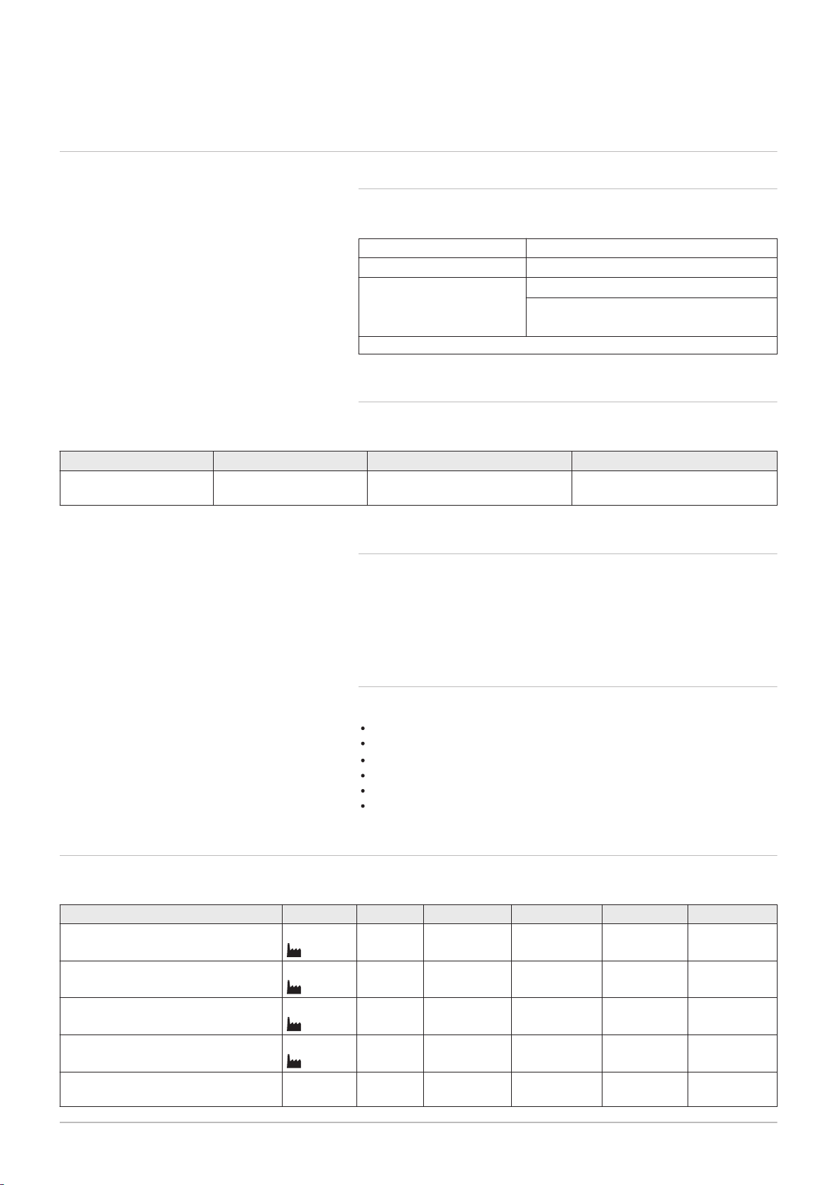
3.1.1 Certifications
Tab.1 Certifications
CE identification number PIN 0063CR3604
Class NOx
(1)
Type of connection B23, B
(1) EN 15502–1
3.1.2 Unit categories
Tab.2 Unit categories
Country Category Gas type Connection pressure (mbar)
Ireland II
2H3B/P
G20 (H gas)
G30/G31 (butane/propane)
6
C
13(X)
C
(10)3(X)
23P
, C
33(X)
, C
20
30
, B
(12)3(X)
33
, C
43P
, C
53(X)
, C
63(X)
, C
93(X)
,
3.1.3 Directives
In addition to the legal requirements and guidelines, the supplementary
guidelines in this manual must also be followed.
Supplements or subsequent regulations and guidelines that are valid at
the time of installation shall apply to all regulations and guidelines
specified in this manual.
3.1.4 Factory test
Before leaving the factory, each boiler is optimally set and tested for:
Electrical safety.
Adjustment of (O2).
Domestic hot water function (For combi-boilers only).
Water tightness.
Gas tightness.
Parameter setting.
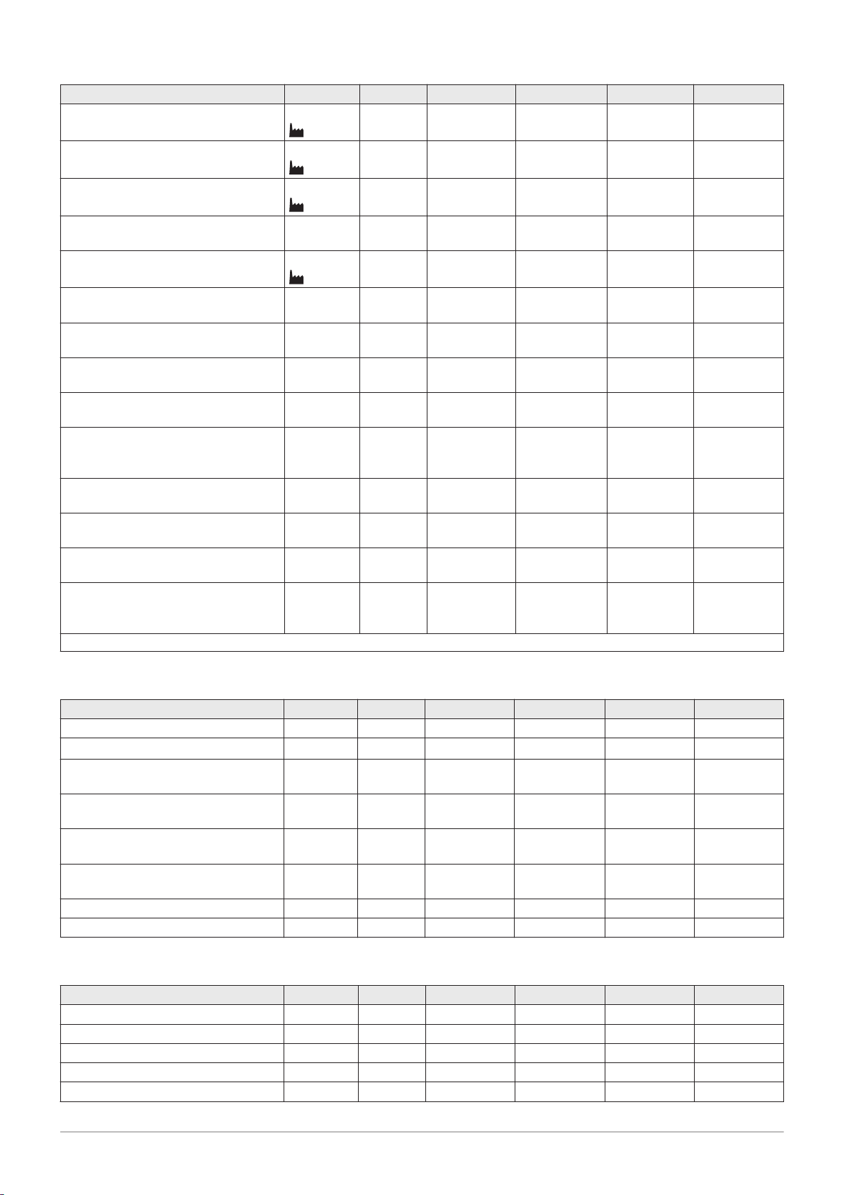
3.2
Tab.3 General
AMC 15 25 25/28 MI 35
Nominal output (Pn) for central heat
ing operation (80 °C/60 °C)
Nominal output (Pn) for central heat
ing operation (50/30 °C)
Nominal output (Pn) for DHW opera
tion
Nominal input (Qnh) central heating
operation (Hi)
Nominal input (Qnh) for central heat
ing operation (Hi) Propane
Technical data
min-max
(1)
min–max
(1)
min–max
(1)
min–max
(1)
kW 3.0 - 14.9
14.9
kW 3.4 - 15.8
15.8
kW -
-
kW 3.1 - 15.0
15.0
5.0 - 24.8
24.8
5.6 - 25.5
25.5
-
-
5.2 - 25.0
25.0
5.0 - 24.8
19.9
5.6 - 25.5
20.5
5.0 - 27.8
27.8
5.2 - 25.0
20.1
7.0 - 34.5
7.9 - 35.6
7.3 - 34.8
min-max 5.2 - 15.0 5.9 - 25.0 5.9 - 25.0 7.3 - 34.8
34.5
35.6
-
-
34.8
Page 10
3 Technical specifications
10 AMC 7686707 - v.01 - 06092018
AMC 15 25 25/28 MI 35
Nominal input (Qnh) central heating
operation (Hs)
Nominal input (Qnh) for central heat
ing operation (Hs) Propane
Nominal input (Qnw) for DHW opera
tion (Hi)
Nominal input (Qnw) for DHW opera
tion (Hi) Propane
Nominal input (Qnw) for DHW opera
tion (Hs)
Nominal input (Qnw) for DHW opera
tion (Hs) Propane
Full load central heating efficiency
min–max
(1)
min-max
(1)
min–max
(1)
min–max kW -
min–max
(1)
min–max kW -
kW 3.4 - 16.7
16.7
5.8 - 27.8
27.8
5.8 - 27.8
22.3
8.1 - 38.7
5.8 - 16.7 6.5 - 27.8 6.5 - 27.8 8.1 - 38.7
kW -
-
-
kW -
-
-
-
-
-
5.2 - 28.0
28.0
5.9 - 28.0 -
-
-
-
-
5.8 - 31.1
31.1
6.5 - 31.1 -
-
% 99.3 99.2 99.2 99.1
(Hi) (80/60 °C) (92/42/EEC)
Full load central heating efficiency
% 105.3 102.0 102.0 102.2
(Hi) (50°C/30°C) (EN15502)
Part load central heating efficiency
% 94.9 96.1 96.1 96.3
(Hi) (return temperature 60°C)
Part load central heating efficiency
% 110.2 110.1 110.1 110.6
(Hi) (92/42/EEC) (return temperature
30°C)
Full load central heating efficiency
% 89.4 89.3 89.3 89.2
(Hs) (80/60°C) (92/42/EEC)
Full load central heating efficiency
% 94.8 91.9 91.9 92.0
(Hs) (50°C/30°C) (EN15502)
Part load central heating efficiency
% 85.5 86.5 86.5 86.7
(Hs) (return temperature 60°C)
Part load central heating efficiency
% 99.2 99.1 99.1 99.6
(Hs) (92/42/EEC) (return temperature
30°C)
(1) Factory setting
38.7
-
-
-
-
-
-
Tab.4 Details of gas and flue gas
AMC 15 25 25/28 MI 35
Gas inlet pressure G20 (H gas) min-max mbar 17 - 25 17 - 25 17 - 25 17 - 25
Gas consumption G20 (H gas) min-max
NOx annual emissions G20 (H gas)
O2 = 0% ppm 17 16 16 27
m3/h
0.33 - 1.59 0.55 - 2.65 0.55 - 2.96 0.77 - 3.68
EN15502
NOx annual emissions G20 (H gas)
H
I
mg/kWh 30 28 28 45
EN15502
NOx annual emissions G20 (H gas)
H
s
mg/kWh 27 25 25 41
EN15502
Flue gas quantity min-max kg/h
g/s
5.5 - 25.3
1.5 - 7.0
9.2 - 42.1
2.6 - 11.7
9.2 - 47.1
2.6 - 13.1
12.7 - 57.4
3.5 - 15.9
Flue gas temperature min-max °C 30 - 59 30 - 74 30 - 81 32 - 79
Maximum counter pressure Pa 80 120 130 140
Tab.5 Central heating circuit data
AMC 15 25 25/28 MI 35
Water content l 1.7 1.7 1.7 2.3
Water operating pressure min bar 0.8 0.8 0.8 0.8
Water operating pressure (PMS) max bar 3.0 3.0 3.0 3.0
Water temperature max °C 110.0 110.0 110.0 110.0
Operating temperature max °C 90.0 90.0 90.0 90.0
Page 11
3 Technical specifications
7686707 - v.01 - 06092018 AMC 11
AMC 15 25 25/28 MI 35
Central heating total dynamic head
mbar 585 355 355 231
(ΔT = 20K)
Casing-related losses ΔT 30°C
ΔT 50°C
W 78
136
78
136
78
136
Tab.6 DHW circuit data
AMC 25/28 MI
Specific hot water flow rate D (60°C) l/min 8.2
Specific hot water flow rate D (40°C) l/min 14.5
Pressure difference on tap water side mbar 329
Flow rate threshold
(1)
max l/min 1.5
Water content l 0.33
Operating pressure (Pmw) bar 8
Minimum flow l/min 2
Score stars 3
(1) Minimum amount of water that comes out of the tap to make the boiler start.
Tab.7 Electrical data
AMC 15 25 25/28 MI 35
Supply voltage V~ 230 230 230 230
Power consumption – full load max
(1)
W 67
67
77
77
84
68
54
121
93
93
Power consumption – part load max W 27 26 26 27
Power consumption – standby max W 4 4 4 4
Electrical protection index
(2)
Fuses
(1) Factory setting.
(2) Splashproof; under certain conditions, the boiler may be installed in damp areas, such as bathrooms.
(3) The fuse is located on the CU-GH08 control unit
IP IPX5D IPX5D IPX5D IPX5D
(3)
CU-GH
A 2.5 2.5 2.5 2.5
Tab.8 Other data
AMC 15 25 25/28 MI 35
Minimum mounting weight
(1)
kg 36 36 38 31
Total weight (empty) kg 38 38 40 33
Average acoustic level at a distance
of one metre from the boiler (LPA)
Central
heating op
dB(A) 37
43
-
-
40
44
eration
DHW oper
ation
(1) Without front panel.
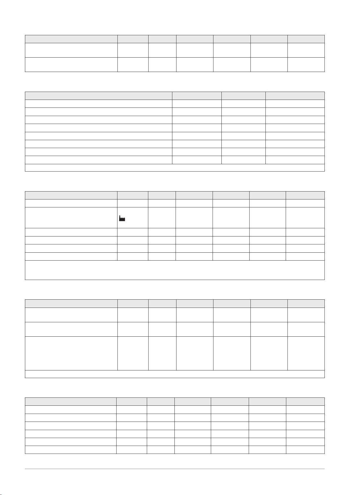
Tab.9 Technical parameters
AMC 15 25 25/28 MI 35
Condensing boiler Yes Yes Yes Yes
Low-temperature boiler
(1)
No No No No
B1 boiler No No No No
Cogeneration space heater No No No No
Combination heater No No Yes No
Rated heat output
Prated
kW 15 25 25 35
31
33
45
-
Page 12

3 Technical specifications
12 AMC 7686707 - v.01 - 06092018
AMC 15 25 25/28 MI 35
Useful heat output at nominal heat
P
4
kW 14.9 24.8 24.8 34.5
output and high temperature oper
(2)
ation
Useful heat output at 30% of rated
P
1
kW 5.0 8.3 8.3 11.6
heat output and low temperature
(1)
regime
Seasonal space heating energy effi
ƞ
s
% 94 94 94 95
ciency
Useful efficiency at rated heat out
put and high temperature regime
Useful efficiency at 30% of rated
ƞ
4
(2)
ƞ
1
% 89.5 89.4 89.4 89.3
% 99.3 99.2 99.2 99.6
heat output and low temperature
(1)
regime
Auxiliary electricity consumption
Full load
Part load
Standby mode
elmax
elmin
P
SB
kW 0.027 0.037 0.037 0.050
kW 0.018 0.017 0.017 0.018
kW 0.004 0.004 0.004 0.004
Other items
Standby heat loss
Ignition burner power consumption
Annual energy consumption
Sound power level, indoors
Emissions of nitrogen oxides NO
P
stby
P
ign
Q
HE
L
WA
X
kW 0.078 0.078 0.078 0.054
kW - - - -
GJ 46 76 76 105
dB(A) 45 51 51 53
mg/kWh 27 25 25 41
Domestic hot water parameters
Declared load profile - - A -
Daily electricity consumption
Annual electricity consumption
Water heating energy efficiency
Daily fuel consumption
Annual fuel consumption
(1) Low temperature means 30°C for condensing boilers, 37°C for low temperature boilers and 50°C (at heater inlet) for other heating appli
ances.
(2) High temperature operation means 60°C return temperature at heater inlet and 80°C feed temperature at heater outlet.
Q
elec
AEC
ƞ
wh
Q
fuel
AFC
kWh - - 0.169 -
kWh - - 37 -
% - - 82.4 -
kWh - - 22.045 -
GJ - - 17 -
See
See the back of this manual for contact information.
Page 13
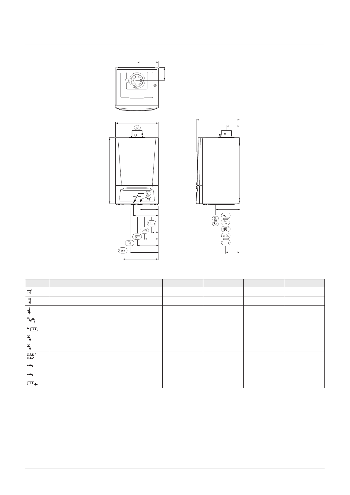
3.3 Dimensions and connections
AD-0001436-02
67
195
265
132
199
266
331
690
450
450
225
140
140
150
255
7686707 - v.01 - 06092018 AMC 13
Fig.1 Dimensions
3 Technical specifications
Tab.10 Connections
AMC 15 25 25/28 MI 35
Connecting the flue gas outlet Ø 60 mm Ø 60 mm Ø 60 mm Ø 60 mm
Connecting the air supply Ø 100 mm Ø 100 mm Ø 100 mm Ø 100 mm
Hose of safety valve Ø 25 mm Ø 25 mm Ø 25 mm Ø 25 mm
Condensation outlet Ø 25 mm Ø 25 mm Ø 25 mm Ø 25 mm
Heating circuit flow (primary circuit) G¾" G¾" G¾" G¾"
Domestic hot water outlet - - G½" -
Heating circuit flow (secondary circuit) G½" G½" - G½"
Gas connection G½" G½" G½" G½"
Domestic cold water inlet - - G½" -
Heating circuit return (secondary circuit) G½" G½" - G½"
Heating return (primary circuit) G¾" G¾" G¾" G¾"
Page 14
AD-0001240-05
12
BK
BK
1 2
X116
51 6
4
BK
BK
3 1
X112
BK
BK
1 3
X113
9
X111
BK
BK
BK
BK
4 2 3 1
X11
14
X91
BK
BK
BK
BK
1 2 4 5
2 3 8 7 4 10 13 15
2 2
RD
3
BK
1
2
X115
BL
1
23
X114
BK
BK
1 2
X113
X10
4
4 7 2 1096
X8
1
BR
BL
GN/
YW
3 1
2 3
2
X41
X7
2 1 3
WH
BK
RD
1 3 2
X121
X6
1 2
GN/
YW
WH
BL
153
3 4
X21
X5
2
BK
BL
GN/
YW
GY
1 23
X22
3 4 1
X4
1
BK
BK
BK
X91
1 2 3
2 3
CB-03
7 81 2 3 4 5 6
R-Bus ToutBL RL
9 10
Tdhw
X1
X136
1 3 4 52
X131
1 3 4 52 6
X13
1 32 54 1 32 54
321
X134
54
321
X135
54
321
X132
54
6 7 8 9 10 11
BK
BK
BK
BK
BK
BK
BK
BK
BK
BK
BK
BK
BK
BK
BK
BK
BK
BK
BK
BK
BK
BK
BK
BK
BK
BK
Spare
X14
1 32
BK
BK
BK
321
X141
22
21
2019
18171615
141312
11
10
8
6
7
9
5
4
3
X11
X13
X12
X4
X3
X10
X8
X7
X14
X6
X5
X3
2 31
X32
1 32
X33
2 31
24
13 X31
2
N L
230V, 50Hz
1
4 132
1 3 42
X01
BR
BL
GN/
YW
BR
BR
BL
BL
GN/
YW
GN/
YW
3 Technical specifications
14 AMC 7686707 - v.01 - 06092018
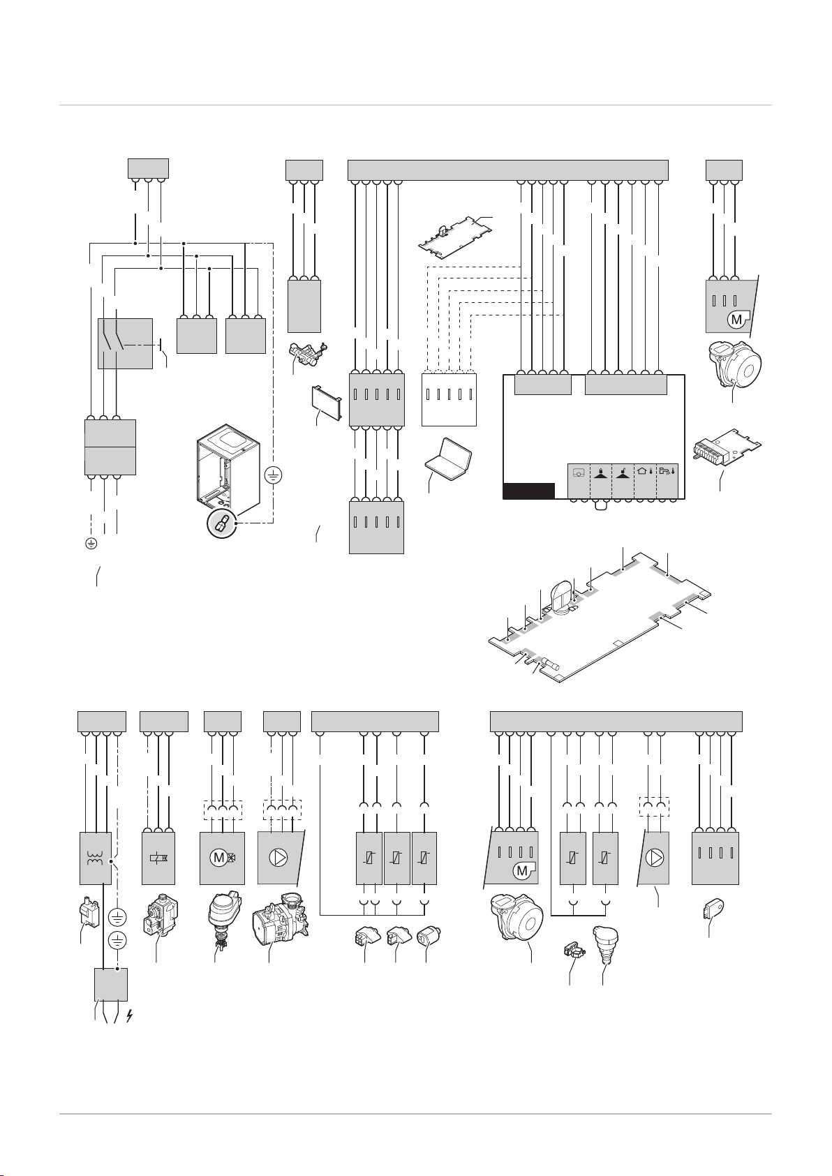
3.4 Electrical diagram
Fig.2 Electrical diagram
Power supply (P)
On/off switch (S)
Automatic refill device
4
5
6
Control unit (CU-GH08)
Display (DIS)
Spare CAN-Bus connection
1
2
3
Page 15

3 Technical specifications
7686707 - v.01 - 06092018 AMC 15
7
Service connection
8
Fan supply
9
CB-03 PCB
10
Ignition transformer (IT)
11
Ionisation/ignition electrode (E)
12
Gas combination block (GB)
13
Three-way valve (3WV)
14
Circulation pump (CH)
15
Flow sensor (FTS)
16
Return sensor (TR)
17
Tap water temperature sensor (TDHW)
18
Fan control (PWM)
19
20
21
22
BK
BL
BR
GN/YW
GY
RD
WH
Flow sensor (FS)
Pressure sensor (PS)
PWM pump
Storage information (CSU)
Black
Blue
Brown
Green/Yellow
Grey
Red
White
Page 16
4 Description of the product
16 AMC 7686707 - v.01 - 06092018
4 Description of the product
The AMC boiler is delivered with a combination of the control panel,
control unit and extension PCB. The contents of this manual are based on
the following software and navigation information:
Tab.11 Software and navigation information
Name visible in display Software version
Boiler AMC CU-GH08 1.4
Control panel Diematic Evolution MK3 1.29
PCB SCB-10 SCB-10 0.5
4.1
General description
4.2 Operating principle
The AMC boiler is a wall-mounted gas boiler with the following
characteristics:
High-efficiency heating
Low polluting emissions
Automatic refill device
High-quality electronic control panel
Easier installation and connection thanks to the mounting frame
delivered with the appliance.
The following boiler types are available:
Type Mode
AMC 15
AMC 25
AMC 35
AMC 25/28 MI Heating and production of domestic hot water.
4.2.1
The boiler has an automatic refill device located under the boiler.
The automatic refill device will refill the central heating system whenever
the water pressure is lower than the set minimum. Refilling can be
automatic or semi-automatic. On the semi-automatic setting, refilling will
only start after confirmation by the user. The automatic refill device can
also be used to fill an empty system.
If refilling takes too long or occurs too often (e.g. because the system
leaks), a warning code will appear on the display and refilling will stop.
Automatic refill device
Heating only (option of producing domestic hot
water using a separate hot water appliance).
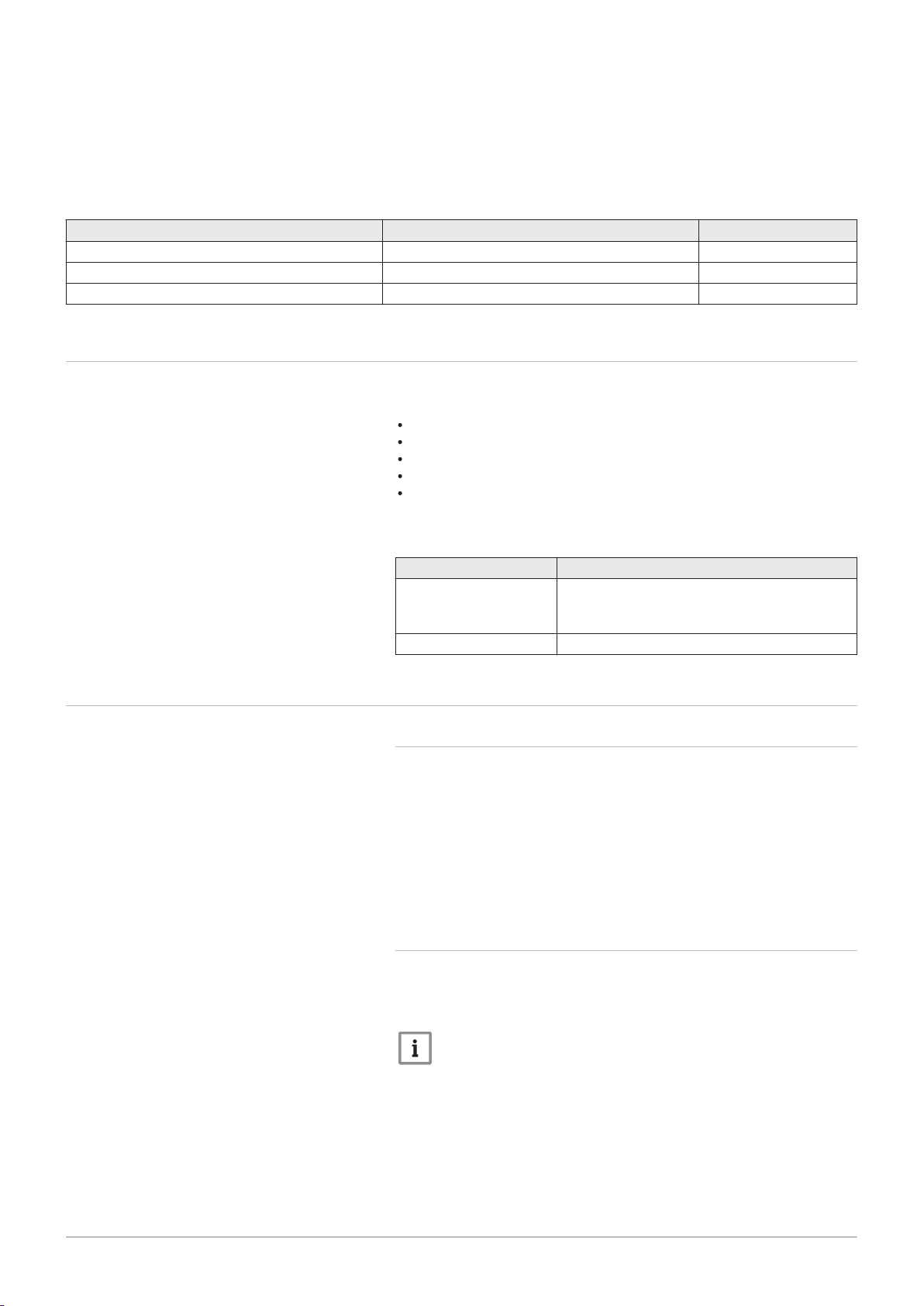
4.2.2
The energy-efficient, modulating circulation pump is controlled by the
control unit based on ΔT. The graphs show the total dynamic head at
various outputs.
Circulation pump
Important
The benchmark for the efficient circulation pumps is EEI ≤ 0.20.
Page 17
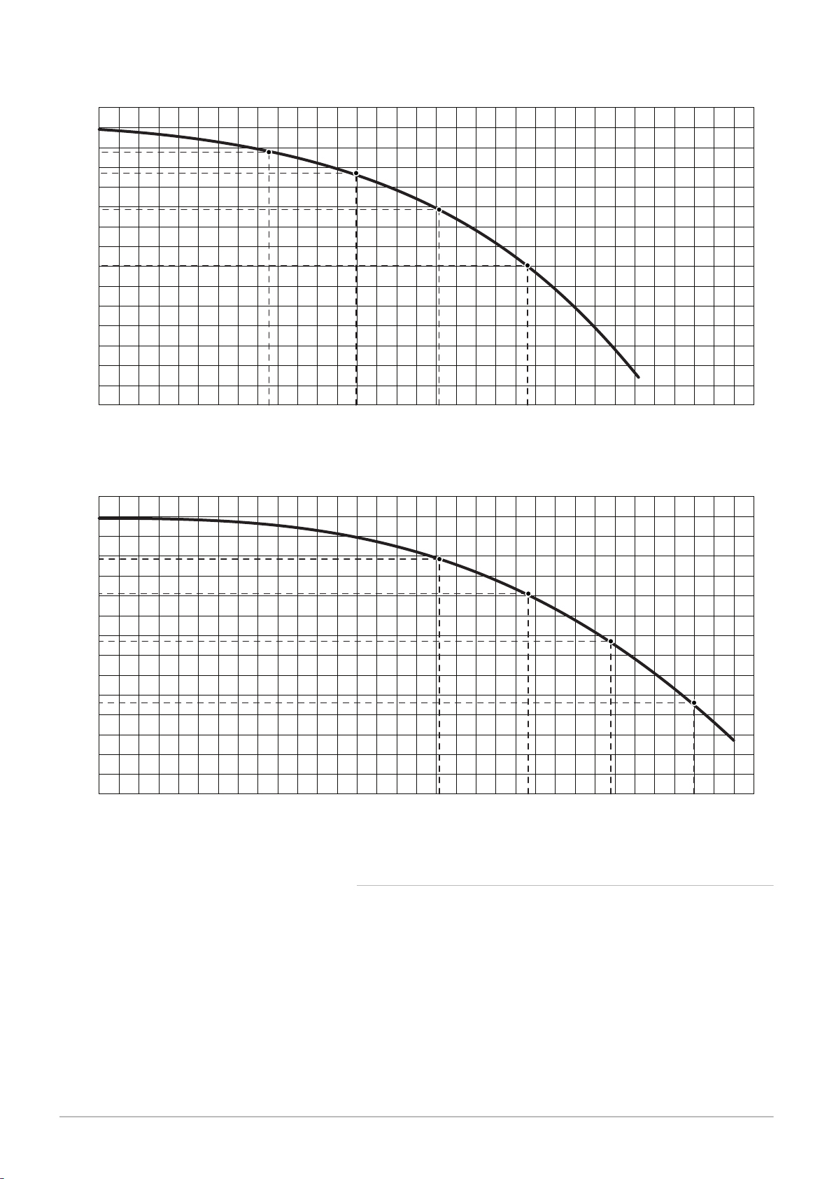
Fig.3 AMC 15 - 25 - 25/28 MI
AD-3000862-02
Q
1600140012001000600 800400200
0
0
100
200
300
400
500
600
H
700
355
25 kW
1080
494
20 kW
860
585
15 kW
650
640
10 kW
430
AD-3000863-02
Q
1600140012001000600 800400200
0
0
100
200
300
400
500
600
H
700
231
35 kW
1500
387
30 kW
1290
508
25 kW
1080
594
20 kW
860
7686707 - v.01 - 06092018 AMC 17
4 Description of the product
H
Total dynamic head CH (mbar)
Fig.4 AMC 35
H
Total dynamic head CH (mbar)
Q
Water flow rate (l/h)
Q
Water flow rate (l/h)
4.2.3 Water flow
The modulating control of the boiler limits the maximum temperature
difference between the flow and return and the maximum rise velocity of
the flow temperature. In addition, a heat exchanger temperature sensor is
mounted to monitor the minimum water flow. As a result, the boiler is
virtually unaffected by low water flow.
Page 18
AD-0000428-01
1
8
7
6
2 3 4 5
AD-3000830-01
1
7
6
2 3 4 5
4 Description of the product
18 AMC 7686707 - v.01 - 06092018
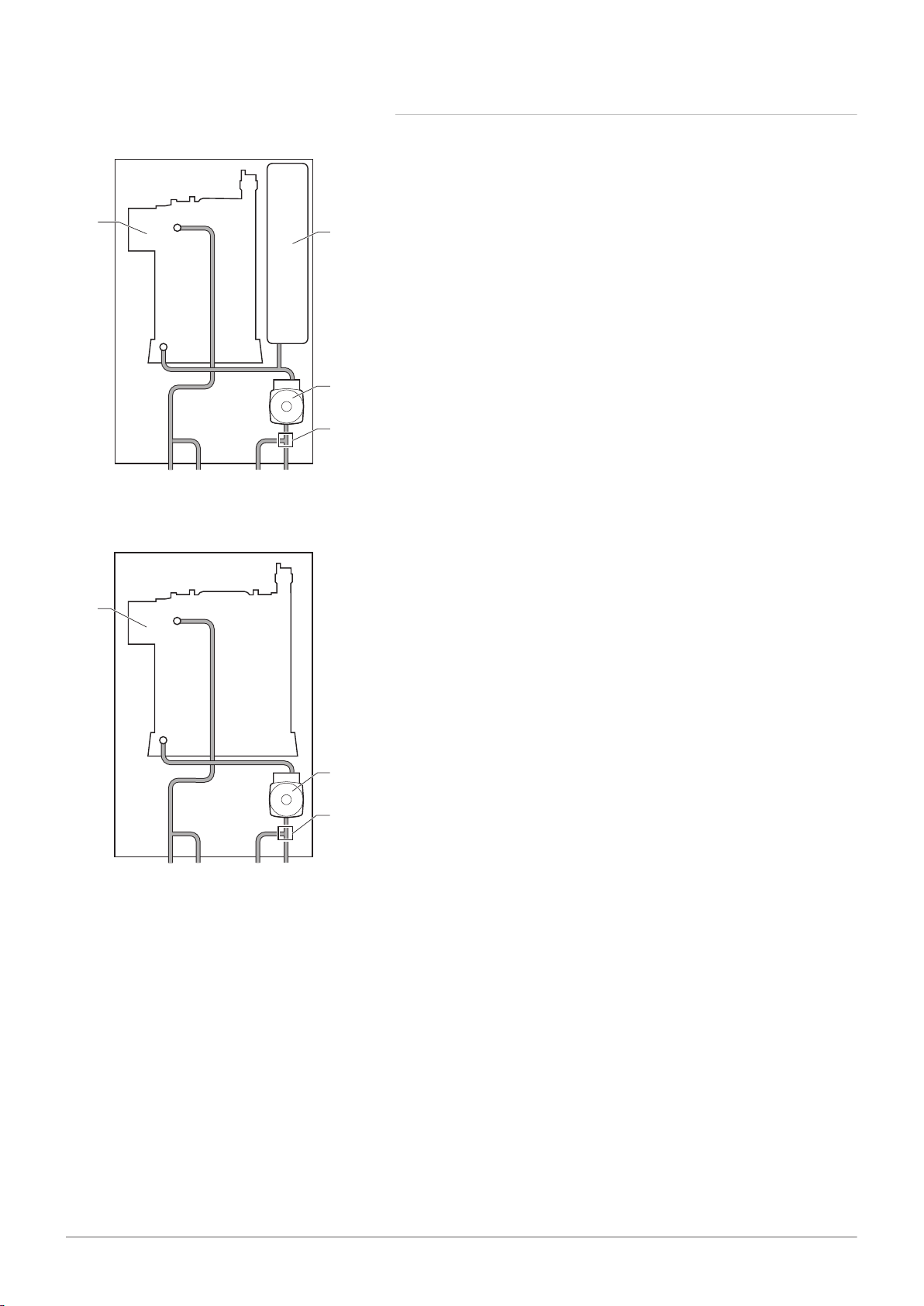
4.2.4 Skeleton diagram
Fig.5 AMC 15 - 25
Fig.6 AMC 35
1
Heat exchanger (CH)
2
Heating circuit flow (primary circuit)
3
Heating circuit flow (secondary circuit)
4
Heating return (secondary circuit)
5
Heating return (primary circuit)
6
Three-way valve
7
Circulation pump (CH)
8
Expansion vessel
1
Heat exchanger (CH)
2
Heating circuit flow (primary circuit)
3
Heating circuit flow (secondary circuit)
4
Heating return (secondary circuit)
5
Heating return (primary circuit)
6
Three-way valve
7
Circulation pump (CH)
Page 19
AD-0000419-01
1
2
3
10
9
8
4 5 6 7
AD-0001371-02
2
16
15
14
17
18
19
20
21
22
3
4
5
6
7
8
9
10
11
12
13
1 23
4 Description of the product
7686707 - v.01 - 06092018 AMC 19
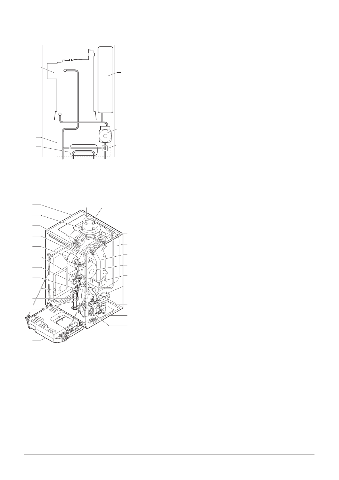
Fig.7 AMC 25/28 MI
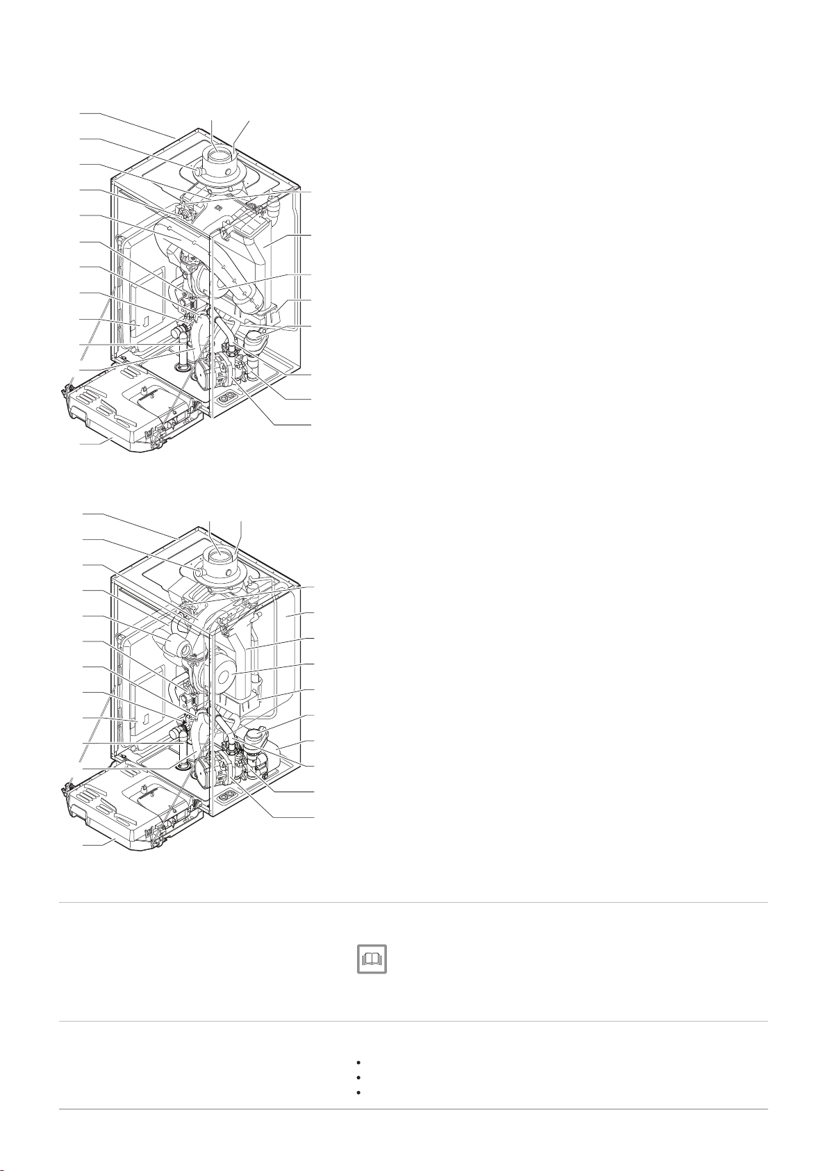
4.3
Main components
Fig.8 AMC 15 - 25
1
Heat exchanger (CH)
2
Hydroblock
3
Plate heat exchanger (DHW)
4
Central heating circuit flow
5
Domestic hot water outlet
6
Domestic cold water inlet
7
Central heating circuit return
8
Three-way valve
9
Circulation pump (CH)
10
Expansion vessel
1
Flue gas outlet
2
Casing/air box
3
Flue gas measuring point
4
Mixing tube
5
Hydraulic flow pipe
6
Air intake silencer
7
Combined gas valve unit
8
Automatic air vent hose
9
Hydroblock, flow side
10
Housing for PCBs
11
Safety valve hose
12
Siphon
13
Instrument box
14
Circulation pump
15
Hydroblock, return side
16
Return pipe
17
Three-way valve
18
Condensate collector
19
Fan
20
Heat exchanger (CH)
21
Expansion vessel
22
Ionisation/ignition electrode
23
Air supply
Page 20
AD-0001372-02
2
15
16
17
14
18
19
20
21
3
4
5
6
7
8
9
13
1
22
10
11
12
AD-0001373-03
2
17
16
15
14
18
19
20
21
22
23
3
4
5
6
8
7
9
10
11
12
13
1 24
4 Description of the product
20 AMC 7686707 - v.01 - 06092018
Fig.9
AMC 35
Fig.10 AMC 25/28 MI
4.4
4.5
Control panel
Standard delivery
1
Flue gas outlet
2
Casing/air box
3
Flue gas measuring point
4
Mixing tube
5
Hydraulic flow pipe
6
Air intake silencer
7
Combined gas valve unit
8
Automatic air vent hose
9
Hydroblock, flow side
10
Housing for PCBs
11
Safety valve hose
12
Siphon
13
Instrument box
14
Circulation pump
15
Hydroblock, return side
16
Return pipe
17
Three-way valve
18
Condensate collector
19
Fan
20
Heat exchanger (CH)
21
Ionisation/ignition electrode
22
Air supply
1
Flue gas outlet
2
Casing/air box
3
Flue gas measuring point
4
Mixing tube
5
Hydraulic flow pipe
6
Air intake silencer
7
Combined gas valve unit
8
Automatic air vent hose
9
Hydroblock, flow side
10
Housing for PCBs
11
Safety valve hose
12
Siphon
13
Instrument box
14
Circulation pump
15
Hydroblock, return side
16
Return pipe
17
Plate heat exchanger (DHW)
18
Three-way valve
19
Condensate collector
20
Fan
21
Heat exchanger (CH)
22
Expansion vessel
23
Ionisation/ignition electrode
24
Air supply
The AMC boiler is supplied with a Diematic Evolution control panel.
For more information, see
Control panel description, page 77
The delivery includes:
The boiler, fitted with a three-core cable
Mounting frame with automatic refill device
Connection kit including cable glands and clamping rings
Page 21

4 Description of the product
7686707 - v.01 - 06092018 AMC 21
Condensate drain hose for siphon and safety valve
Condensates collector
Seal plates for sealing off the lines for the secondary heating circuit if it
is not being used
Documentation
Mounting template
Sticker: This central heating unit is set for ...
This manual only deals with the standard scope of supply. For the
installation or mounting of any accessories supplied with the boiler, please
refer to the mounting instructions delivered with the accessories in
question.
Page 22
AD-0001197-01
AD-0001376-02
450
min.10
0
0
4
5
0
min.
250
m
i
n.
2
5
0
690
5 Before installation
22 AMC 7686707 - v.01 - 06092018
5 Before installation
5.1 Installation regulations
Warning
The boiler must be installed by a qualified installer in accordance
with local and national regulations.
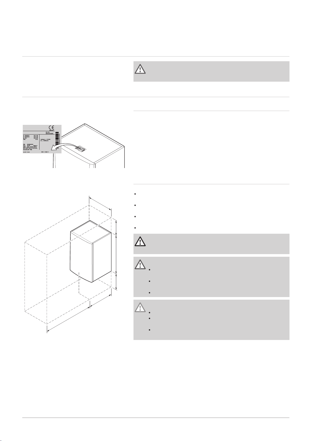
5.2
Choice of the location
Fig.11 Position of data plate
Fig.12 Installation area
5.2.1 Data plate
The data plate on top of the boiler states the boiler serial number and
important boiler specifications such as the model and gas category. The
configuration numbers CN1 and CN2 codes are also stated on the data
plate.
5.2.2 Location of the boiler
Use the guidelines and the required installation space as a basis for
determining the correct place to install the boiler.
When determining the correct installation area, take account of the
permitted position of the flue gas outlet and/or air supply outlet.
Ensure that there is sufficient space around the boiler for good access
and ease of maintenance.
Mount the boiler onto a flat surface.
Danger
It is forbidden to store, even temporarily, combustible products
and substances in the boiler or near the boiler.
Warning
Fix the appliance to a solid wall capable of bearing the weight of
the boiler when full of water and fully equipped.
Do not place the appliance above a heat source or a cooking
appliance.
Do not locate the boiler in direct or indirect sunlight.
Caution
The boiler must be installed in a frost-free area.
An earthed electrical connection must be available close to the
boiler.
A connection to the drain must be present for the condensate
drain close to the boiler.
Page 23
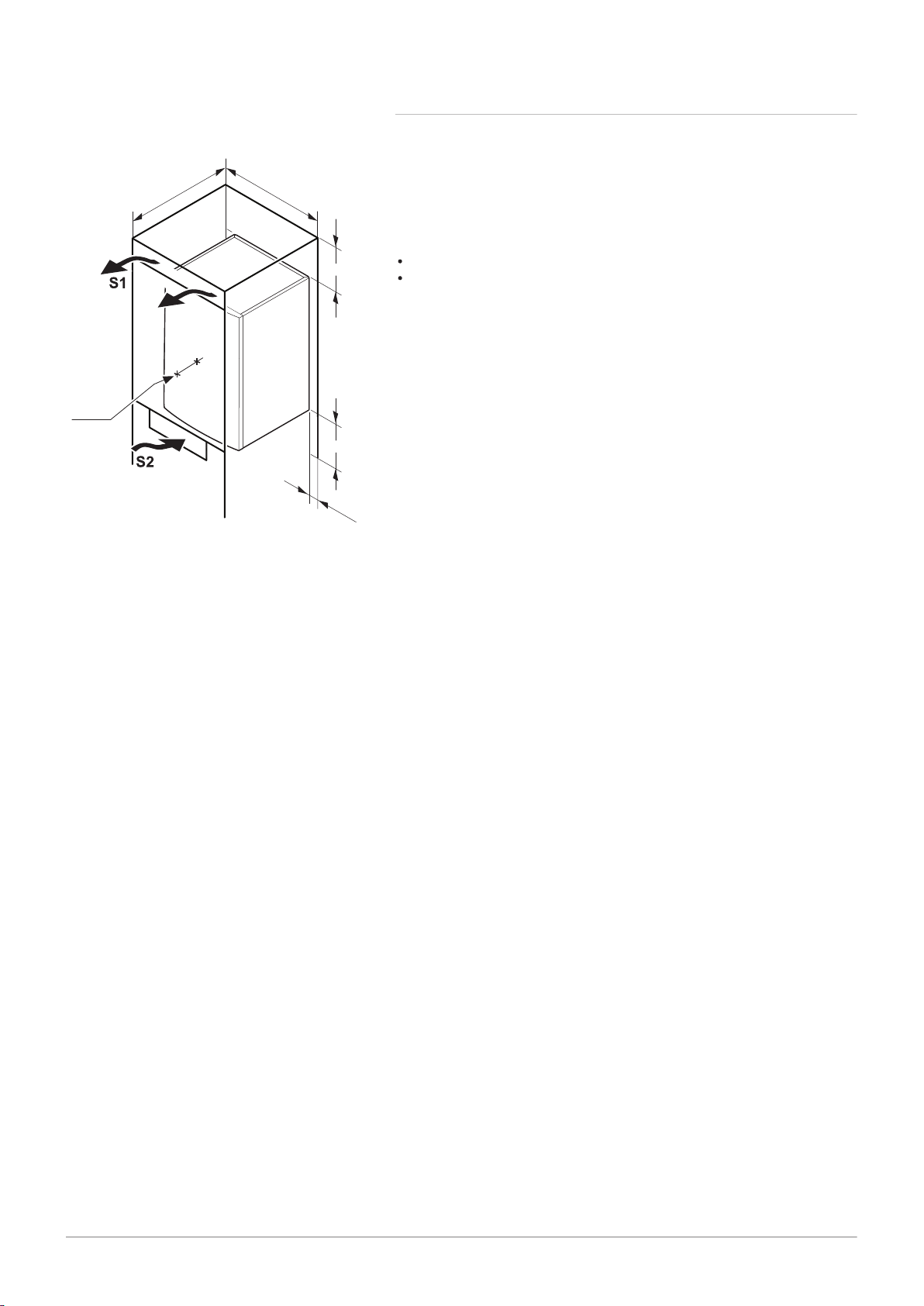
5.2.3 Ventilation
AD-0001377-02
min. 550
min.550
min. 250
50 (2)
min. 250
100
min. (1)
7686707 - v.01 - 06092018 AMC 23
5 Before installation
Fig.13
Space for ventilation
(1)
Distance between the front of the boiler and the internal wall of the
casing.
(2)
Space on either side of the boiler.
If the boiler is installed in a closed casing, observe the minimum
dimensions indicated. Also allow for openings to prevent the following
hazards:
Accumulation of gas
Heating of the casing
Minimum cross section of the openings: S1 + S2 = 150 cm
2
Page 24
AD-0001379-02
76499
0
2
-01
50
57
41
13
152,5
154,5
216
216
2
20
220
2
6,5
120
432
450
6
76
7
6
7
6565
63
50
1
95
690
42
487
715
3
6
100
59
10
(1x)
10
(1x)
1
0
(1x)
104,5
1
04,5
5
1
0
(1
x
)
1
0
(1x)
1
2
3
4
5
6 Installation
24 AMC 7686707 - v.01 - 06092018
6 Installation
6.1 General
Warning
The boiler must be installed by a qualified installer in accordance
with local and national regulations.
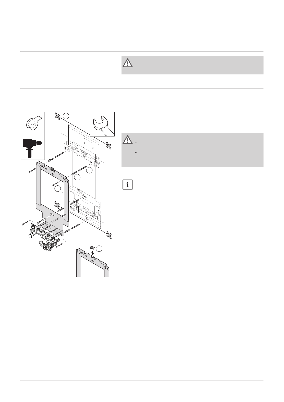
6.2
Preparation
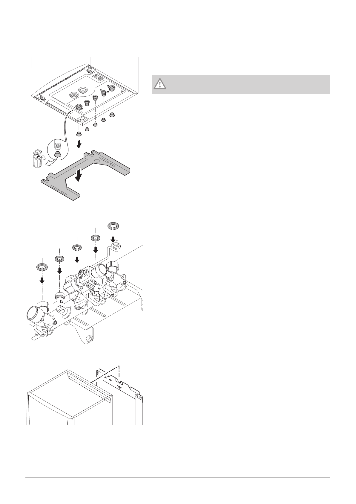
Fig.14 Installing the mounting frame
6.2.1 Installing the mounting frame
The boiler is supplied with a mounting template.
Proceed as follows to hang the mounting frame:
1. Attach the mounting template of the boiler to the wall using adhesive
tape.
Warning
Use a level on the mounting frame to check whether the
mounting template is perfectly horizontal.
Protect the boiler against building dust and cover the flue gas
outlet and air supply connection points. Only remove this cover
to assemble the relevant connections.
2. Drill 3 holes of Ø 10 mm.
Important
The extra holes are intended for use in the event that one of the
two fastening holes is not suitable for correct fastening of the plug.
3. Fit the Ø 10 mm plugs.
4. Attach the mounting frame to the wall with the Ø 8 mm screws
supplied
5. Remove the level from the mounting frame.
Page 25
6.2.2 Positioning the boiler
AD-0001380-02
AD-0001381-02
AD-3001203-01
7686707 - v.01 - 06092018 AMC 25
6 Installation
Fig.15 Removing boiler protection
Fig.16 Fitting gaskets
1. Remove the black protective strip on the underside of the boiler.
2. Remove the dust caps from all of the hydraulic inlets and outlets on
the boiler.
Caution
The valve of the filling loop must be closed.
3. Fit a fibre gasket to each joint on the valve plate.
Fig.17 Fitting the boiler
4. Position the boiler above the mounting frame. Gently lower the boiler.
5. Tighten the valve nuts on the boiler.
Page 26
AD-0001383-03
1
2
AD-0001384-03
2
1
6 Installation
26 AMC 7686707 - v.01 - 06092018
6.3 Hydraulic connections
6.3.1 Rinsing the system
Installation must be carried out in accordance with the prevailing
regulations, codes of practice and the recommendations in this manual.
Before a new boiler can be connected to an existing or new system, the
entire system must be thoroughly cleaned and flushed. This step is
absolutely crucial. The flushing helps to remove residue from the
installation process (weld slag, fixing products etc.) and accumulations of
dirt (silt, mud etc.)
Important
Flush the system with a volume of water equivalent to at least
three times the volume of the system. Flush the DHW pipes with a
volume of water equivalent to at least 20 times the volume of the
pipes.
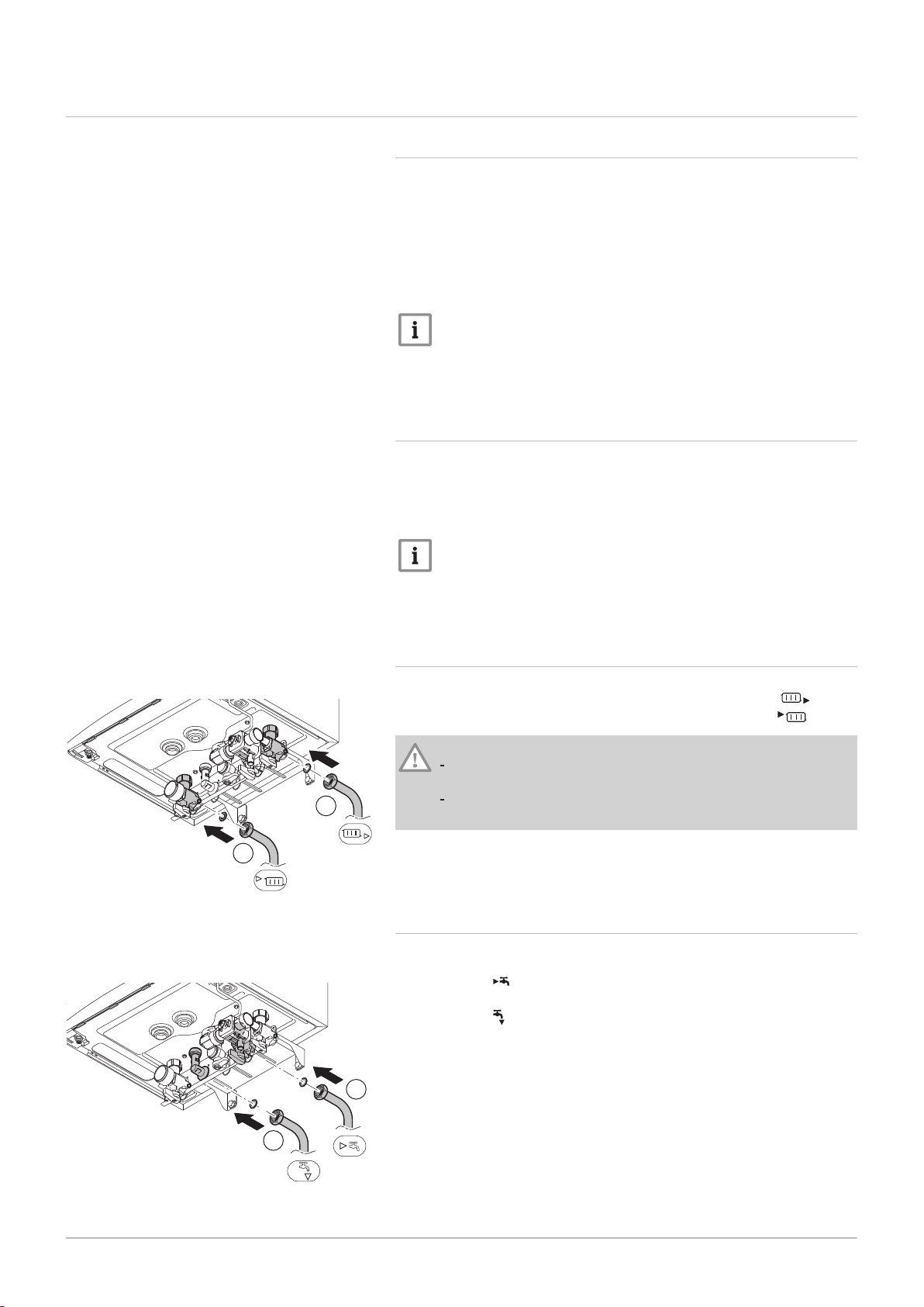
Fig.18 Connecting the heating circuit
6.3.2
Water flow
The boiler's modulating control system limits the maximum difference in
temperature between the heating flow and return, and the maximum
speed at which the flow temperature increases. In this way, the boiler does
not require a minimum water flow rate.
Important
In the case of a combi boiler in an installation in which the flow
can be fully disconnected from the return (e.g. by using
thermostatic valves), a bypass pipe should be fitted or the
expansion vessel placed on the central heating flow pipe.
6.3.3
Connection of the heating circuit
1. Fit the inlet pipe for CH water to the CH return connection .
2. Fit the outlet pipe for CH water to the CH flow connection .
Caution
Carry out any welding work required at a safe distance from the
boiler or before the boiler is fitted.
If using synthetic pipes, follow the manufacturer's (connection)
instructions.
6.3.4 Connection of the water circuit for domestic use
Fig.19 Connecting water circuit for
domestic use
1. Connect the cold water inlet pipe to the domestic cold water
connection .
2. Connect the domestic hot water outlet pipe to the domestic hot water
connection
Page 27
Caution
AD-0001385-04
4
3
2
1
AD-0001207-03
1
2
7686707 - v.01 - 06092018 AMC 27
If using synthetic pipes, follow the manufacturer's (connection)
instructions.
Carry out any welding work required at a safe distance from the
boiler or before the boiler is fitted.
6.3.5 Connecting the secondary heating circuit
6 Installation
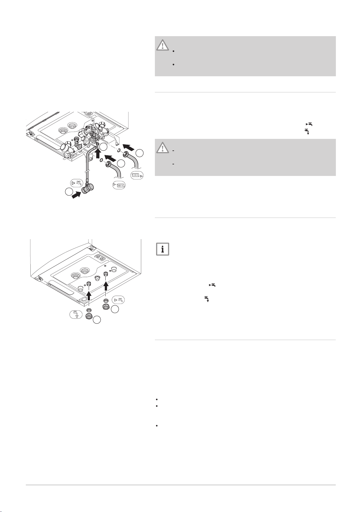
Fig.20 Connecting the secondary heating
circuit
Fig.21 Disconnecting the secondary
heating circuit
1. Fit the pipe supplied with the mounting frame to the domestic cold
water connection of the automatic (re)fill device.
2. Connect the domestic cold water inlet to this pipe.
3. Fit the inlet pipe for CH water to the CH return connection .
4. Fit the outlet pipe for CH water to the CH flow connection .
Caution
Carry out any welding work required at a safe distance from the
boiler or before the boiler is fitted.
If using synthetic pipes, follow the manufacturer's (connection)
instructions.
6.3.6
Disconnecting the secondary heating circuit
These connections must be closed off if the secondary heating circuit is
not connected (solo use of the boiler). To do this, proceed as follows:
Important
The blanking plates needed are supplied with the boiler.
1. Remove the secondary heating circuit valves from the mounting
frame.
2. Place a blanking plate in the fitting (G½") and install this on the CH
return connection .
3. Place a blanking plate in the fitting (G½") and install this on the CH
flow connection .
6.3.7 Connecting the expansion vessel
The boiler is fitted as standard with an 12 litre expansion vessel.
If the water volume is greater than 150 litres or the static height of the
system exceeds 5 metres, an additional expansion vessel must be fitted.
Refer to the table below to determine the expansion vessel required for
the system.
Validity terms of the table:
3-bar safety valve
Average water temperature: 70°C
Flow temperature: 80°C
Return temperature: 60°C
The filling pressure in the system is lower than or equal to the inflation
pressure in the expansion vessel.
Page 28
AD-3001204-01
1
2
4
4
3
3
AD-0001387-03
1
6 Installation
28 AMC 7686707 - v.01 - 06092018
Tab.12 Volume of the expansion vessel (litres)
Initial pressurinstae of the ex
pansion vessel
Volume of the system (litres)
100 125 150 175 200 250 300 > 300
0.5 bar 4.8 6.0 7.2 8.4 9.6 12.0 14.4 Volume of the system x 0.048
1 bar 8.0 10.0
(1
14.0 16.0 20.0 24.0 Volume of the system x 0.080
12.0
)
1.5 bar 13.3 16.6 20.0 23.3 26.6 33.3 39.9 Volume of the system x 0.133
(1) Standard configuration.
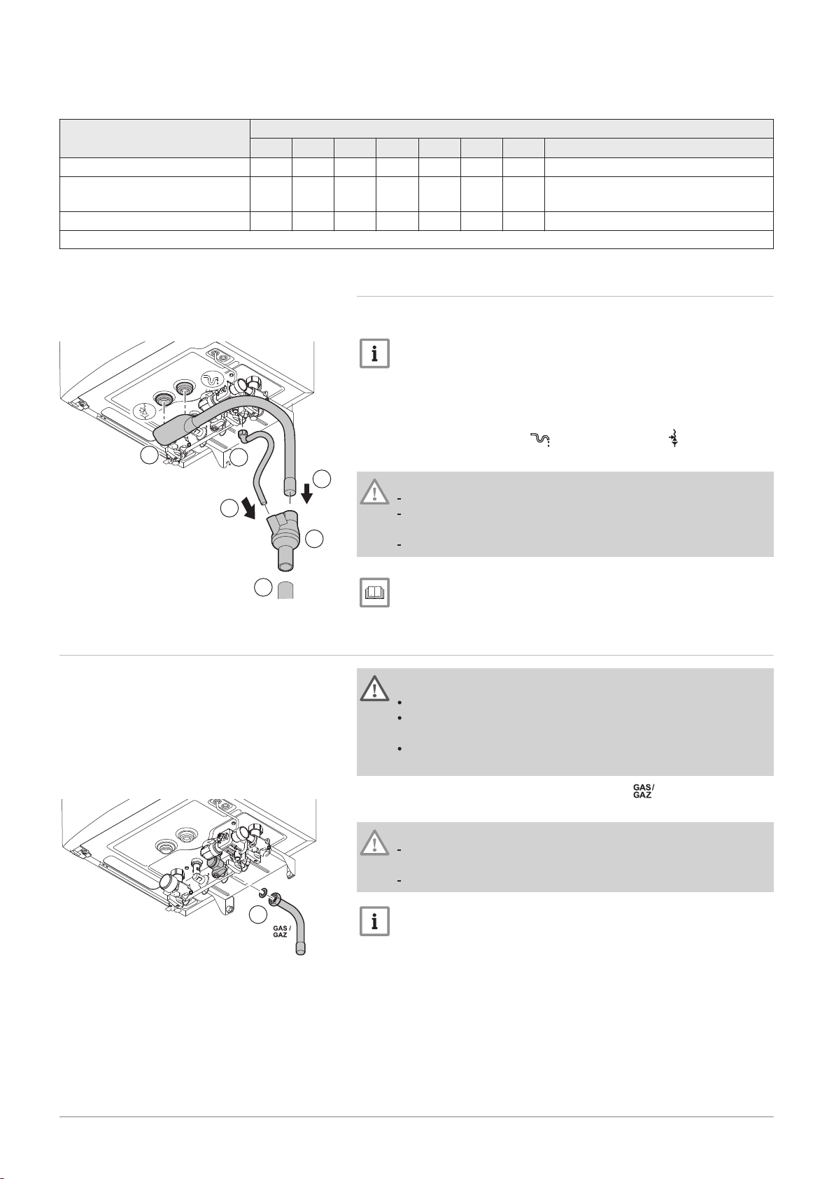
6.3.8 Connecting the condensate drain pipe
Fig.22 Connecting the condensate
discharge pipe
6.4 Gas connection
1. Fit a plastic drain pipe of Ø 32 mm or larger, terminating in the drain.
Important
Fit a watertrap or siphon in the drain pipe.
2. Insert the condensate collector into the drain pipe.
3. Attach the boiler siphon and safety valve drain hose to the condensate
discharge pipe connection and the safety valve .
4. Slide the hose into the drain pipe.
Caution
Never seal the condensate drain.
The drain pipe must slope down at least 30 mm per metre, the
maximum horizontal length is 5 metres.
Condensed water must not be discharged into a gutter.
For more information, see
Filling the siphon, page 66
Warning
Before starting work on the gas pipes, turn off the main gas tap.
Before installing, check that the gas meter has sufficient
capacity. Take into account the consumption of all appliances.
Notify the local energy company if the gas meter has insufficient
capacity.
Fig.23 Connecting the gas pipe
1. Fit the gas supply pipe to the gas connection .
2. Fit the gas pipe to the gas tap.
Caution
Always perform welding work at a sufficient distance from the
boiler.
Remove dirt and dust from the gas pipe.
Important
We recommend installing a gas filter to prevent clogging of the
gas valve unit.
Page 29
6.5 Air supply/flue gas outlet connections
AD-3000924-01
AD-3000925-01
AD-3000926-01
AD-3000927-01
7686707 - v.01 - 06092018 AMC 29
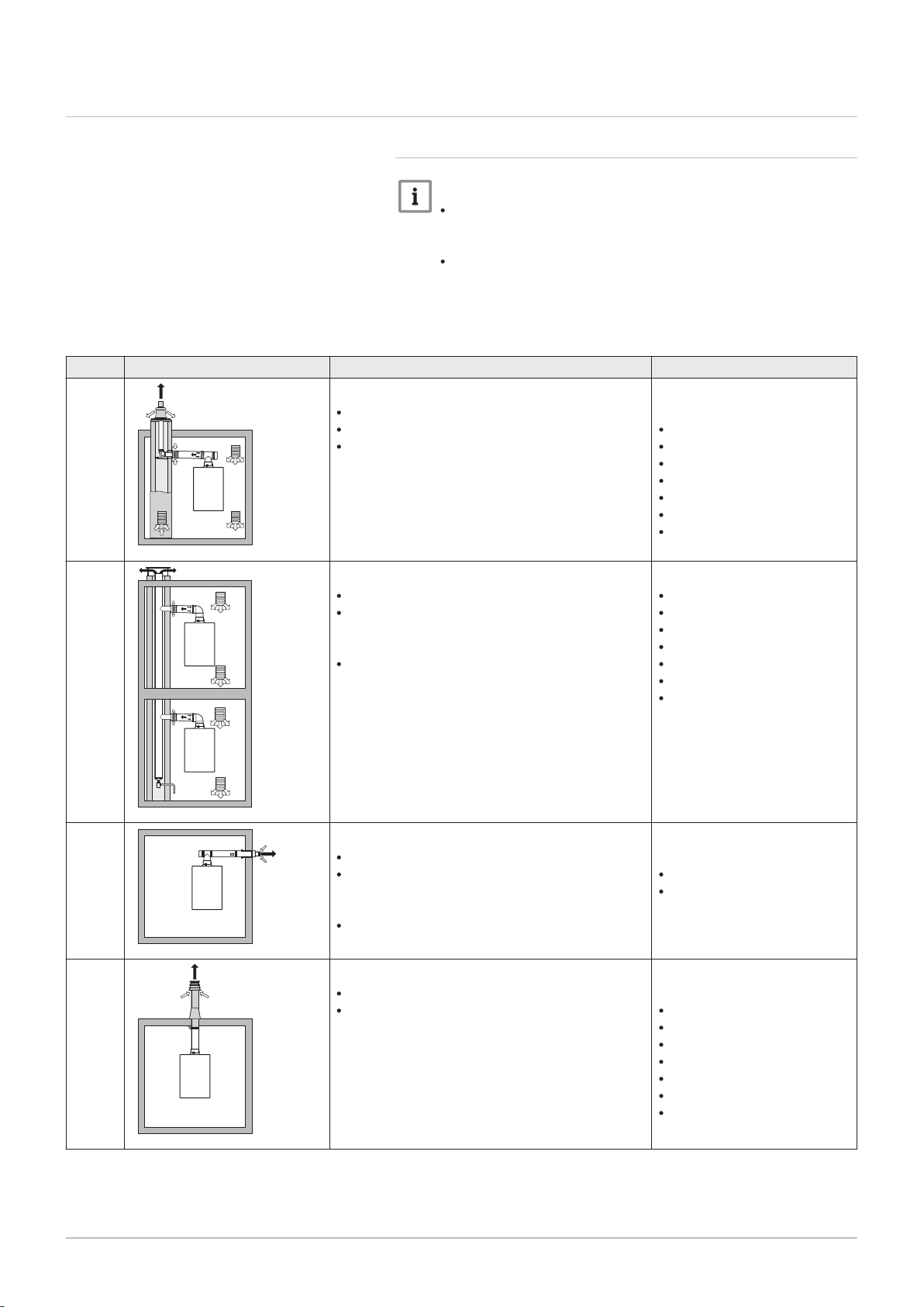
Tab.13 Types of flue gas connections
Type Principle Description
B
23
B
23P
Room-ventilated version
Without down-draught diverter.
Flue gas discharge via the roof.
Air from the installation area.
6.5.1 Classification
Important
The installer is responsible ensuring that the right type of flue
gas outlet system is used and that the diameter and length are
correct.
Always use connection materials and roof terminal supplied by
the same manufacturer. Consult the manufacturer for
compatibility details.
6 Installation
Permitted manufacturers
(1)
Connection material and roof
terminal:
Centrotherm
Cox Geelen
Muelink & Grol
Natalini
Poujoulat
Skoberne
Ubbink
B
C
C
33
13(X)
33(X)
Room-ventilated version
Without down-draught diverter.
Joint flue gas discharge via the roof, with guar
anteed natural draft. (at all times underpressure
in the joint discharge duct)
Flue gas discharge rinsed with air, air from the
installation area (special construction).
Room-sealed version
Discharge in the outside wall.
Inlet opening for the air supply is in the same
pressure zone as the discharge (e.g. a com
bined outside wall feed-through).
Parallel not permitted
Room-sealed version
Flue gas discharge via the roof.
Inlet opening for the air supply is in the same
pressure zone as the discharge (e.g. a concen
tric roof feed-through).
Connection material:
Centrotherm
Cox Geelen
Muelink & Grol
Natalini
Poujoulat
Skoberne
Ubbink
Outside wall terminal and con
nection material:
Cox Geelen
Muelink & Grol
Roof terminal and connection
material
Centrotherm
Cox Geelen
Muelink & Grol
Natalini
Poujoulat
Skoberne
Ubbink
Page 30
AD-3000928-01
AD-3000929-02
AD-3000931-01
6 Installation
30 AMC 7686707 - v.01 - 06092018
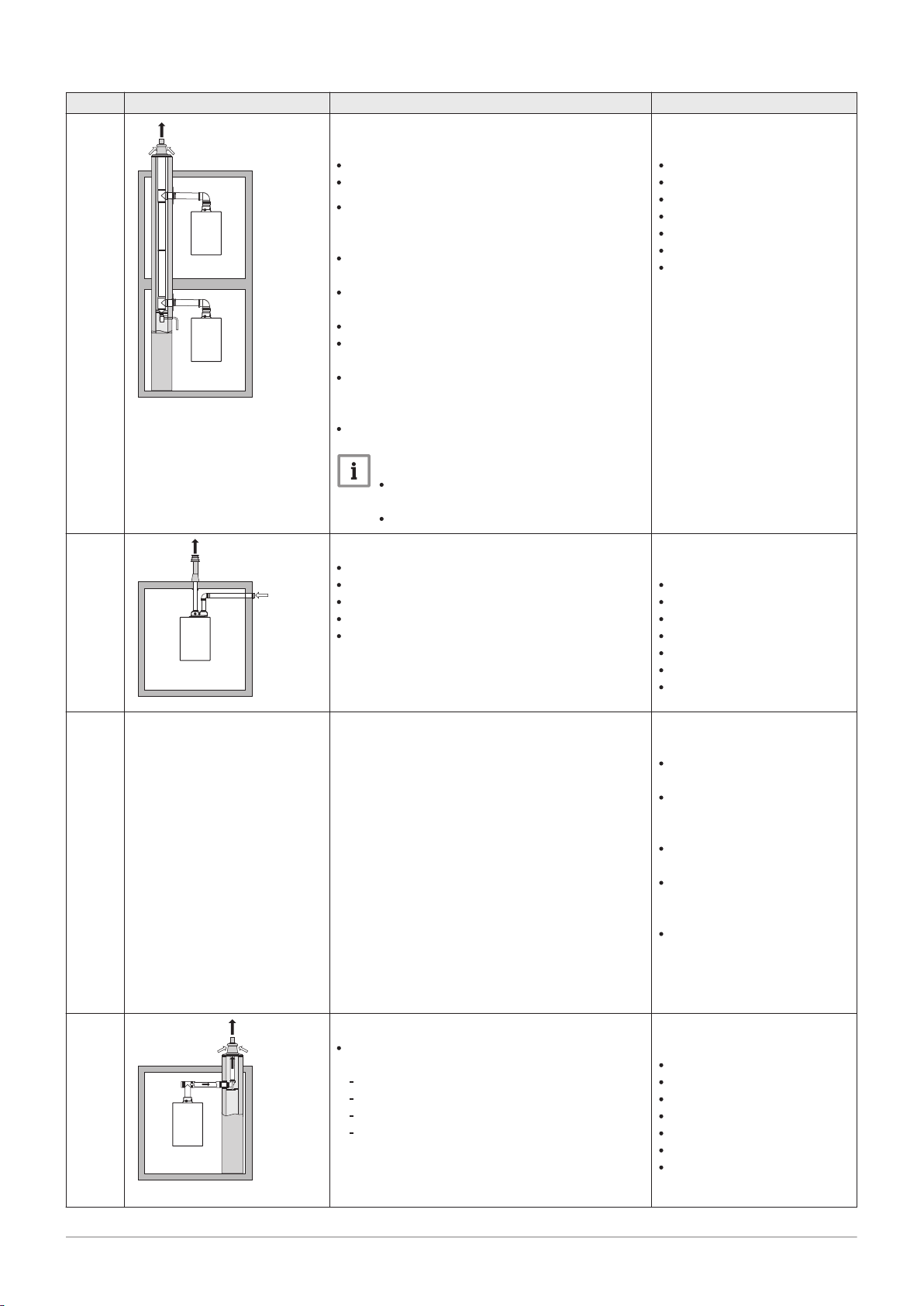
Type Principle Description
C
43P
(2)
Combined air supply and flue gas outlet system
(CLV) with overpressure.
Concentric (preferably).
Parallel (if concentric is not possible).
Minimum permitted pressure difference between
the air supply and the flue gas outlet is -200 Pa
(including -100 Pa wind pressure).
The channel must be designed for a nominal
flue gas temperature of 25°C
Place a condensation drain, equipped with a si
phon, at the bottom of the channel.
Maximum permissible recirculation of 10%.
The common outlet should be appropriate for a
pressure of at least 200 Pa.
The roof feed-through must be designed for this
configuration and must cause a draught in the
channel.
A draught diverter is not permitted.
Important
The fan speed must be adapted for
this configuration.
Contact us for more information.
C
53(X)
Connection in different pressure zones
Closed unit.
Separate air supply duct.
Separate flue gas discharge duct.
Discharging into various pressure areas.
The air supply and the flue gas outlet must not
be placed on opposite walls.
Permitted manufacturers
(1)
Connecting material to the
common channel:
Centrotherm
Cox Geelen
Muelink & Grol
Natalini
Poujoulat
Skoberne
Ubbink
Connection material and roof
terminal:
Centrotherm
Cox Geelen
Muelink & Grol
Natalini
Poujoulat
Skoberne
Ubbink
C
C
(3)
63(X)
93(X)
This type of unit is supplied by the manufacturer
without a supply and discharge system.
Room-sealed version
Air supply and flue gas discharge duct in shaft
or ducted:
Concentric.
Air supply from existing duct.
Flue gas discharge via the roof.
Inlet opening for the air supply is in the same
pressure zone as the discharge.
When selecting the material,
please note the following:
Condensed water must flow
back to the appliance
The material must be resist
ant to the flue gas tempera
ture of this appliance.
Maximum permissible recir
culation of 10%.
The air supply and the flue
gas outlet must not be placed
on opposite walls.
Minimum permitted pressure
difference between the air
supply and the flue gas outlet
is -200 Pa (including -100 Pa
wind pressure).
Connection material and roof
terminal:
Centrotherm
Cox Geelen
Muelink & Grol
Natalini
Poujoulat
Skoberne
Ubbink
Page 31

AD-3000959-01
AD-3000930-01
6 Installation
7686707 - v.01 - 06092018 AMC 31
Type Principle Description
C
(10)3(X)
Combined air supply and flue gas outlet system
(CLV) with overpressure
Minimum permitted pressure difference between
the air supply and the flue gas outlet is -200 Pa
(including -100 Pa wind pressure).
The channel must be designed for a nominal
flue gas temperature of 25°C
Place a condensation drain, equipped with a si
phon, at the bottom of the channel.
Maximum permissible recirculation of 10%.
The common outlet should be appropriate for a
pressure of at least 200 Pa.
The roof feed-through must be designed for this
configuration and must cause a draught in the
channel.
A draught diverter is not permitted.
Important
The fan speed must be adapted for
this configuration.
Contact us for more information.
C
(12)3(X)
Common flue gas outlet and individual air supply
(half CLV)
Minimum permitted pressure difference between
the air supply and the flue gas outlet is -200 Pa
(including -100 Pa wind pressure).
The channel must be designed for a nominal
flue gas temperature of 25°C
Place a condensation drain, equipped with a si
phon, at the bottom of the channel.
Maximum permissible recirculation of 10%.
The common outlet should be appropriate for a
pressure of at least 200 Pa.
The roof feed-through must be designed for this
configuration and must cause a draught in the
channel.
A draught diverter is not permitted.
Permitted manufacturers
(1)
Connecting material to the
common channel:
Centrotherm
Cox Geelen
Muelink & Grol
Natalini
Poujoulat
Skoberne
Ubbink
Connecting material to the
common channel:
Centrotherm
Cox Geelen
Muelink & Grol
Natalini
Poujoulat
Skoberne
Ubbink
Important
The fan speed must be adapted for
this configuration.
Contact us for more information.
(1) The material must also satisfy the material property requirements from the relevant chapter.
(2) EN 15502-2-1: 0.5 mbar suction due to depression
(3) See table for shaft or duct requirements
6.5.2
Requirements for shaft for C
93
Tab.14 Minimum dimensions of shaft or duct
Version (D) Without air supply With air supply
Ø duct □ duct Ø duct □ duct
Rigid 60 mm 110 mm 110 x 110 mm 120 mm 110 x 110 mm
Rigid 80 mm 130 mm 130 x 130 mm 140 mm 130 x 130 mm
Concentric 60/100 mm 120 mm 120 x 120 mm 120 mm 120 x 120 mm
Concentric 80/125 mm 145 mm 145 x 145 mm 145 mm 145 x 145 mm
Page 32

AD-3000330-02
□
D
Ø
D
AD-3001120-01
EN 14471 - T120 P1 W 1 O50 LI E U0
EN 1856-1 - T120 P1 W VxL40045 G(xx)
1
3
2
4
5
6 Installation
32 AMC 7686707 - v.01 - 06092018
Fig.24 Minimum dimensions of shaft or
duct
Fig.25 Sample string
Important
The shaft must comply with the air density requirements of the
local regulations.
Important
Always clean shafts thoroughly when using lining pipes and/or
an air supply connection.
It must be possible to inspect the lining duct.
6.5.3 Material
Use the string on the flue gas outlet material to check whether it is suitable
for use on this appliance.
1
EN 14471 of EN 1856–1: The material is CE approved according to
this standard. For plastic this is EN 14471, For aluminium and
stainless steel this is EN 1856-1.
2
T120: The material has temperature class T120. A higher number
is also allowed, but not lower.
3
P1: The material falls into pressure class P1. H1 is also allowed.
4
W: The material is suitable for draining condensation water
(W=’wet’). D is not allowed (D=’dry’).
5
E: The material falls into fire resistance class E. Class A to D are
also allowed, F is not allowed. Only applicable to plastic.
Tab.15 Overview of material properties
Version Flue gas outlet Air supply
Material Material properties Material Material properties
Single-wall, rigid
Plastic
Stainless steel
Thick-walled,
aluminium
(1) according to EN 14471
(2) according to EN 1856
(3) according to EN 13501-1
Warning
The coupling and connection methods may vary depending on
the manufacturer. It is not permitted to combine pipes, coupling
and connection methods from different manufacturers. This also
applies to roof feed-throughs and common channels.
The materials used must comply with the prevailing regulations
and standards.
(1)
(2)
With CE marking
(2)
Temperature class T120 or
higher
Condensate class W (wet)
Plastic
Stainless steel
Aluminium
With CE marking
Pressure class P1 or H1
Fire resistance class E or bet
(3)
ter
Pressure class P1 or H1
Fire resistance class E or bet
(3)
ter
Page 33

6.5.4 Dimensions of flue gas outlet pipe
AD-3000962-01
ød
1
L
1
øD
1
AD-0001356-01
L
=
7686707 - v.01 - 06092018 AMC 33
Warning
The pipes connected to the flue gas adapter must satisfy the
following dimension requirements.
6 Installation
Fig.26 Dimensions of concentric
connection
d
External dimensions of flue gas outlet pipe
1
D
External dimensions of air supply pipe
1
L
Length difference between flue gas outlet pipe and air supply pipe
1
Tab.16 Dimensions of pipe
d1 (min-max) D1 (min-max)
(1)
L
(min-max)
1
60/100 mm 59.3 - 60.3 mm 99 - 100.5 mm 0 - 15 mm
80/125 mm 79.3 - 80.3 mm 124 - 125.5 mm 0 - 15 mm
(1) Shorten the inner pipe if the length difference is too great.
6.5.5 Length of the air and flue gas pipes
The maximum length of the flue gas outlet and air supply channel vary
depending on the appliance type; consult the relevant chapter for the
correct lengths.
Important
When using bends, the maximum chimney length (L) must be
shortened according to the reduction table.
For adaptation to another diameter use approved transitions
Fig.27 Room-ventilated version
Room-ventilated model (B23, B
L
Length of the outlet duct, including roof feed-through
23P
, B33)
Connecting the flue gas outlet
Connecting the air supply
With a room-ventilated version, the air supply opening stays open; only the
flue gas outlet opening is connected. This will ensure that the boiler
obtains the necessary combustion air directly from the installation area.
Use adapters when using air supply and flue gas outlet pipes with any
other diameter.
Caution
The air supply opening must stay open.
The installation area must be equipped with the necessary air
supply openings. These openings must not be obstructed or
shut off.
Tab.17 Maximum chimney length (L)
Diameter 60 mm 70 mm 80 mm 90 mm
(1)
AMC 15
AMC 25
AMC 25/28 MI
AMC 35
(1) While maintaining maximum length, additional 5 times 90º or 10 times 45º
bends can be used.
33 m 40 m 40 m
19 m 35 m 40 m
16 m 30 m 40 m
13 m 25 m 40 m 40 m
(1)
(1)
(1)
40 m
40 m
40 m
(1)
(1)
(1)
(1)
Page 34

AD-0001357-01
L =
AD-0001212-01
L = +
6 Installation
34 AMC 7686707 - v.01 - 06092018
Fig.28 Room-sealed version
Fig.29 Different pressure zones
Room-sealed model (C
L
Total length of the flue gas outlet and air supply duct
13(X)
, C
33(X)
, C
63(X)
, C
93(X)
)
Connecting the flue gas outlet
Connecting the air supply
With a room-sealed version, both the flue gas outlet and the air supply
openings are connected (concentrically). Refer to the table to determine
the maximum pipe length of the flue gas outlet pipes in the room-sealed
version.
Tab.18 Maximum chimney length (L)
Diameter 60/100 mm
AMC 15
AMC 25
AMC 25/28 MI
AMC 35
(1) Retaining the maximum length, it is possible to use an extra 5 x 90º or 10 x
45º elbows.
20 m 20 m
13 m 20 m
11 m 20 m
9 m 20 m
Connection in different pressure areas (C
L
Total length of the flue gas outlet and air supply duct
53(X)
80/125 mm
)
(1)
(1)
(1)
(1)
(1)
Connecting the flue gas outlet
Connecting the air supply
Important
An 80/80 mm flue gas adapter (accessory) must be fitted for this
connection.
A combustion air supply and flue gas outlet are possible in different
pressure areas and semi-CLV systems, The maximum permitted height
difference between the combustion air supply and the flue gas outlet is 36
m.
Important
Contact us for more information on usage in coastal areas.
Tab.19 Maximum chimney length (L)
Diameter 60 mm 70 mm 80 mm
AMC 15
AMC 25
AMC 25/28 MI
19 m 40 m 40 m
12 m 25 m 40 m
10 m 22 m 40 m 40 m
(1)
(1)
90 mm
40 m
40 m
(1)
(1)
(1)
(1)
AMC 35 7 m 14 m 37 m 40 m
(1) Retaining the maximum length, it is possible to use an extra 5 x 90º or 10 x
45º elbows.
Page 35

AD-0001357-01
L =
AD-0001212-01
L = +
6 Installation
7686707 - v.01 - 06092018 AMC 35
Fig.30 Room-sealed version
Fig.31 Different pressure zones
CLV overpressure system (C
L
Total length of the flue gas outlet and air supply duct
43P
, C
(10)3(X)
, C
(12)3(X)
concentric)
Connecting the flue gas outlet
Connecting the air supply
For a concentric version of C
it is allowed to add 2 m extra to the
(12)3(X)
length of the flue gas discharge.
Tab.20 Maximum chimney length (L)
Diameter 60/100 mm
AMC 15
AMC 25
AMC 25/28 MI
17 m
11 m
9 m
80/125 mm
(1)
20 m
(1)
20 m
(1)
20 m
AMC 35 6 m 20 m
(1) Retaining the maximum length, it is possible to use an extra 5 x 90º or 10 x
45º elbows.
Half CLV overpressure system ( C
L
Total length of the air supply duct and flue gas outlet duct to the
(12)3(X)
parallel)
common part
Connecting the flue gas outlet
Connecting the air supply
(1)
Important
The maximum permitted height difference between the
combustion air supply and the flue gas outlet is 36 m.
Tab.21 Maximum chimney length (L)
Diameter 60/100 mm
AMC 15
AMC 25
AMC 25/28 MI
22 m
12 m
12 m
80/125 mm
40 m
40 m
40 m
(1)
(1)
(1)
(1)
AMC 35 7 m 40 m
(1) Retaining the maximum length, it is possible to use an extra 5 x 90º or 10 x
45º elbows.
Reduction table
Tab.22 Pipe reduction for each element used (parallel)
Diameter 60 mm 70 mm 80 mm 90 mm 100 mm 110 mm 130 mm
45° bend 0.9 m 1.1 m 1.2 m 1.3 m 1.4 m 1.5 m 1.6 m
90° bend 3.1 m 3.5 m 4.0 m 4.5 m 4.9 m 5.4 m 6.2 m
Tab.23 Pipe reduction for each element used (concentric)
Diameter 60/100 mm 80/125 mm 100/150 mm
45° bend 1.0 m 1.0 m 1.0 m
90° bend 2.0 m 2.0 m 2.0 m
Page 36

AD-0001216-01
S
60/100 mm
80/125 mm
6 Installation
36 AMC 7686707 - v.01 - 06092018
6.5.6 Additional guidelines
Installation
For installing the flue gas outlet and air supply materials, refer to the
instructions of the manufacturer of the relevant material. After
installation, check at least all flue gas outlet and air supply parts for
tightness.
Warning
If the flue gas outlet and air supply materials are not installed in
accordance with the instructions (e.g. not leak-proof, not correctly
bracketed), this can result in dangerous situations and/or physical
injury.
Make sure that the flue gas outlet pipe towards the boiler has a sufficient
gradient (at least 50 mm per metre) and that there is a sufficient
condensate collector and discharge (at least 1 m before the outlet of the
boiler). The bends used must be larger than 90° to guarantee the
gradient and a good seal on the lip rings.
Condensation
Direct connection of the flue gas outlet to structural ducts is not
permitted because of condensation.
If condensate from a plastic or stainless steel pipe section can flow back
to an aluminium part in the flue gas outlet, this condensate must be
discharged via a collector before it reaches the aluminium.
Fig.32 Connecting the flue gas outlet and
air supply
Important
Contact us for more information.
6.5.7 Connecting the flue gas outlet and air supply
S Insertion depth 30 mm
Mounting
1. Connect the flue gas outlet pipe and the air supply pipe to the boiler.
2. Fit the subsequent flue gas outlet pipes and air supply pipes in
accordance with the manufacturer's instructions.
Page 37

6 Installation
7686707 - v.01 - 06092018 AMC 37
Caution
The pipes must not be resting on the boiler.
Fit the horizontal parts sloping down towards the boiler, with a
gradient of 50 mm per metre.
6.6
Electrical connections
6.6.1 Recommendations
Warning
Electrical connections must always be made with the power
supply disconnected and only by qualified installers.
The boiler is completely pre-wired. Never change the internal
connections of the control panel.
Make sure you establish an earth connection before connecting
the electricity.
Establish the electrical connections in accordance with:
The instructions of the current standards.
The instructions of the wiring diagrams supplied with the boiler.
The recommendations in this manual.
Separate the sensor cables from the 230 V cables.
Caution
Outside the central heating boiler: Use 2 cables spaced at least
10 cm apart.
6.6.2 Control unit
The table gives important connection values for the control unit.
Supply voltage 230 VAC/50Hz
Main fuse value F1 (230 VAC) 2.5 AT
Danger of electric shock
The following components of the boiler are connected to a 230 V
power supply:
Electrical connection of the circulation pump
Electrical connection to gas valve unit 230 VAC or 230 RAC.
Fan
Electrical connection of the three-way valve
The majority of components in the control unit
Ignition transformer
Connection of supply cable
Automatic refill device (accessory)
The boiler has a three-wire mains lead (lead length 1.5 m) and is suitable
for a 230 VAC/50 Hz power supply with a phase/neutral/earth system. The
boiler is not phase sensitive. The power supply cable is connected to the
X01 connector in the instrument box. A spare fuse can be found in the
casing of the control unit. There is a service port for a PC/laptop next to
the control panel on the boiler.
Caution
Always order a replacement mains lead from De Dietrich. The
power supply cable should only be replaced by De Dietrich, or
by an installer certified by De Dietrich.
The boiler switch must be easily accessible at all times.
Important
All external connections can be made to the CB-03 (low-voltage)
PCB.
Page 38

AD-0001217-04
1
5
X1
1
AD-3000968-01
Tm
R-Bus
6 Installation
38 AMC 7686707 - v.01 - 06092018
The boiler has several control, protection and regulation connection
options. The standard PCB can be extended with optional PCBs.
6.6.3 Connecting a PC/laptop and diagnostic tools
There is a service port for a PC/laptop/smart phone/tablet next to the
control panel on the boiler. Using the Recom PC/Smart Service app, you
can enter, change and read out various boiler settings.
The service port is behind the flap on the front of the boiler.
6.6.4 Access to the connectors
Fig.33 Access to the connectors
The instrument box contains a standard CB-03 PCB with an X1 connector.
Various thermostats and regulators can be connected to the standard
PCB. The various connection options on the standard PCB are detailed in
the following sections.
Access to the connectors:
1. Open the instrument box by undoing the clip fastener at the side.
2. Guide the cables from the regulator or the thermostat through the
round grommet(s) on the right-hand side of the boiler bottom plate.
3. Guide the relevant connection cable(s) through the instrument box via
the grommet(s) provided.
4. Undo the pull relief clip(s) and feed the cable(s) underneath.
5. Connect the cables to the appropriate terminals on the connector.
6. Press the pull relief clips firmly into place
7. Close the instrument box.
For more information, see
Opening boiler, page 104
Fig.34 Connecting the modulating
thermostat
6.6.5 Connection options for the standard PCB
Connecting the modulating thermostat
The boiler is fitted with an R-bus connection as standard It is possible
without further modification to connect a modulating thermostat such as
the De Dietrich Smart TC° thermostat or an OpenTherm modulating
thermostat. The boiler is also suitable for OpenTherm Smart Power.
Tm Modulating thermostat
1. In the case of a room thermostat: install the thermostat in a reference
room.
2. Connect the two-wire cable from the modulating thermostat (Tm) to
the R-Bus terminals of the connector. It does not matter which wire is
connected to which cable clamp.
Important
If the tap water temperature can be set on the thermostat, the
boiler will supply this temperature (with the value set in the boiler
as a maximum).
Connecting the on/off thermostat
The boiler is suitable for connection to a 2-wire on/off ambient thermostat.
Page 39

AD-3000969-01
Tk
R-Bus
AD-3000970-01
TvTk
R-Bus
6 Installation
7686707 - v.01 - 06092018 AMC 39
Fig.35 Connecting the on/off thermostat
Fig.36 Connection of frost thermostat
Tk On/off thermostat
1. Fit the thermostat in a reference room (generally the living room).
2. Connect the two-wire cable of the thermostat (Tk) to the R-Bus
terminals of the connector. It does not matter which wire is connected
to which cable clamp.
Frost protection combined with on/off thermostat
When an on/off thermostat is used, the pipes and radiators in a frostsensitive room can be protected by a frost thermostat. The radiator valve
in the frost-sensitive room must be open.
Tk On/off thermostat
Tv Frost thermostat
1. Place a frost thermostat (Tv) in a frost-sensitive room (e.g. a garage).
2. Connect the frost thermostat (Tv) parallel to the on/off thermostat (Tk)
on the R-Bus terminals for the connector.
Warning
If a De Dietrich Smart TC° or OpenTherm thermostat is used, a
frost thermostat cannot be connected in parallel to the R-Bus
terminals. In that case, implement frost protection of the central
heating system in combination with an outside sensor.
Frost protection combined with outside sensor
The central heating system can also be protected against frost in
combination with an outside sensor. The radiator valve in the frostsensitive room must be open.
Important
For boilers with an SCB-10 PCB, the outdoor sensor is connected
to the SCB-10 PCB.
The frost protection works as follows with an outside sensor:
If the outside temperature in lower than -10°C: heat demand from the
boiler and the pump starts working.
If the outside temperature is higher than -10°C: no heat demand from
the boiler.
Important
The outside temperature before the start of frost protection can be
changed with parameter AP080.
Connecting an outside sensor
An outside sensor can be connected to the Tout connector. In the case of
an on/off thermostat, the boiler will control the temperature with the set
point from the internal heating curve.
See
Adjusting the heating curve, page 81
Important
For boilers with an SCB-10 PCB, the outdoor sensor is connected
to the SCB-10 PCB.
Important
An OpenTherm controller can also use this outside sensor. In that
case, the desired internal heating curve must be set on the
controller.
Page 40

AD-3000971-01
Tdhw
BLR-Bus RL Tout Tdhw
AD-0001234-02
BLR-Bus RL Tout Tdhw
AD-0001235-02
6 Installation
40 AMC 7686707 - v.01 - 06092018
Fig.37
Connecting the calorifier sensor/ thermostat
Connecting the calorifier sensor/thermostat
A calorifier sensor or thermostat can be connected to the Tdhw terminals
of the connector.
1. Connect the plug from the calorifier sensor or calorifier thermostat to
the Tdhw connector.
Blocking input
Fig.38 Blocking input
Fig.39 Release input
The boiler has a blocking input (Normally Closed contact). This input
relates to the BL terminals of the connector.
If this contact is opened, the boiler will be blocked or locked out.
Change the function of the input with parameter setting AP001.
Important
First remove the bridge if this input is used.
Warning
Only suitable for potential-free contacts.
For more information, see
CU-GH08 control unit settings, page 85
Release input
The boiler has a release input (Normally Open contact). This input relates
to the RL terminals of the connector.
If this contact is closed when there is a heat demand, the boiler will be
blocked after a waiting time.
Change the waiting time of the input with parameter setting AP008.
Page 41

Warning
AD-3001210-01
X2 X3
+TA-
TA
Tsyst Tsyst Tdhw Tflow Tflow Tflow
C AB21
R-Bus
Tout
R-Bus
R-Bus
12
3
4
+ -
Status
C AB
0-10V
N L
B
N
N L TS
N L
TS
A
N
23
2218 2019 21
5
14131211 15 16 17
43
21
109876
AD-0001388-04
4
6
7686707 - v.01 - 06092018 AMC 41
Only suitable for potential-free contacts.
6 Installation
Fig.40 Access to the PCB
6.6.6
Access to the PCB housing
1. Unscrew the two screws located under the front panel by a quarter
turn.
2. Remove the front panel.
3. Tilt the instrument box forwards by opening the clips on the sides.
4. Remove the air intake silencer.
5. Unclip the 4 clips on the left side of the PCB housing cover.
6. Swing the cover to the right and pull it forward to remove the cover
from the boiler.
7. Connect the cables to the appropriate terminals on PCB SCB-10.
8. Position the upper hinges of the cover in the right position of the PCB
housing.
9. Press all hinges of the cover into place.
10. Close the 4 clips on the left side of the cover.
11. Fit the air intake silencer.
12. Reassemble the front panel in the reverse order.
For more information, see
Opening boiler, page 104
6.6.7 Description of the SCB-10 PCB
Fig.41 SCB-10 PCB
Different heating zones can be connected to the SCB-10 PCB. Two zones
are designated for heating and one for domestic hot water.
The connections for the sensors or pumps of each zone are on the PCB.
1 Outdoor temperature sensor
2 Programmable and 0-10 V input
3 Room temperature sensor - circuit C
4 Room temperature sensor - circuit B
Page 42

6 Installation
42 AMC 7686707 - v.01 - 06092018
5 Room temperature sensor - circuit A
6 Domestic hot water tank pump
7 3-way valve - circuit B
8 Pump and safety thermostat - circuit B
9 Three-way valve - circuit A
10 Pump and safety thermostat - circuit A
11 System sensor 1
12 System sensor 2
13 Domestic hot water sensor
14 Flow sensor - circuit C
15 Flow sensor - circuit B
16 Flow sensor - circuit A
17 Impressed current anode
18 Connectors Mod-BUS
19 Coding wheel, selects the generator number in the
cascade in Mod-Bus
20 S-BUS connector
21 END connector for L-BUS connection
22 L-BUS connection to control unit (CU-XXXX)
23 S-BUS cable connector
Tab.24 Compatibility of connections
Circuit A Circuit B Circuit C
(with AD249 op
tion)
AUX circuit
(with AD249 op
tion)
Domestic hot wa
ter circuit
Convection fan Yes Yes Yes No No
Underfloor heating Yes Yes Yes No No
Radiator Yes Yes Yes No No
365 day radiator Yes Yes Yes No No
Continuous heating Yes Yes Yes No No
Timer programme Yes Yes Yes Yes Yes
Swimming pool Yes Yes Yes No No
Domestic hot water produc
Yes Yes Yes Yes Yes
tion
Domestic hot water produc
Yes Yes Yes No No
tion, electric only
Stratified tank (2 sensors) No No No No Yes
Deactivation Yes Yes Yes Yes Yes
Caution
Connect the TAS (Titan Active System) anode of the calorifier
tank to the connector TA. If the calorifier tank does not have a
TAS anode, connect the simulation anode (= accessory)
The SCB-10 PCB has the following features;
control of 2 (mixing) zones fitted on connector X15
control of a third (mixing) zone via an PCB (= accessory) fitted on
connector X8
control of one domestic hot water (DHW) zone
cascade layout (add sensor on sensor system 1 or 2)
Important
If the boiler is fitted with the SCB-10 board, then this is
automatically recognised by the automatic control unit of the
boiler.
On removing this board, the boiler will show an error code. To
prevent this error, carry out an auto-detect immediately after
removing this board.
For more information, see
Carrying out an auto-detect for the CAN matrix, page 99
Page 43

Connecting a three-way valve
AD-4000002-02
A
N
B
N
AD-4000001-03
N L
TS
N L
TS
AD-0001132-02
N L
AD-4000006-02
T out
7686707 - v.01 - 06092018 AMC 43
6 Installation
Fig.42
Three-way valve
Fig.43 Pump with protection thermostat
Connecting a three-way valve (230 VAC) per zone (group).
The three-way valve is connected as follows:
= earth
N = neutral
= open
= closed
Connecting the pump with a protection thermostat
Connecting a pump with a protection thermostat, e.g. for underfloor
heating. The maximum pump power consumption is 300 VA.
Connect the pump and the protection thermostat as follows:
= earth
N = neutral
L = phase
= protection thermostat (remove bridge)
Connecting a domestic hot water (DHW) pump
Fig.44 DHW pump
Fig.45 Outside sensor
Connecting a domestic hot water (DHW) pump The maximum power
consumption is 300 VA.
Connect the pump as follows:
= earth
N = neutral
L = phase
Connecting an outside sensor
An outside sensor can be connected to the S out terminals of the
connector. In the case of an on/off thermostat, the boiler will control the
temperature with the set point from the internal heating curve.
Page 44

AD-4000004-02
Status
12
3
4
+
0-10V
-
AD-4000003-02
R-Bus R-Bus R-Bus
C B A
AD-4000008-02
Tsyst Tsyst
1 2
6 Installation
44 AMC 7686707 - v.01 - 06092018
Connecting a telephone connector
Fig.46
Telephone connector
Fig.47 External room thermostats
The telephone connector can be used to connect a remote control, a 0–10
V analogue input or as a status output.
The 0–10 V signal controls the boiler flow temperature in a linear way. This
control modulates on the basis of flow temperature. The output varies
between the minimum and maximum value on the basis of the flow
temperature set point calculated by the controller.
Connect the telephone connector as follows:
1 + 2 = 0–10 V / status input
3 + 4 = status output
Connecting external room thermostats
Connecting external room thermostats per group (zone).
The contacts work with an on/off thermostat, a room thermostat, an
OpenTherm controller or an OpenTherm Smart Power controller.
RU.A = room thermostat
RU.B = room thermostat
RU.C = room thermostat
Fig.48 System sensors
Connecting system sensors
Connecting system sensors for circuits (zones).
S.SYST.1 = system sensor (NTC 10k Ohm/25°C)
S.SYST.2 = system sensor (NTC 10k Ohm/25°C)
Page 45

Connecting the domestic hot water (DHW) sensor
AD-4000009-02
Tdhw
AD-4000007-02
TflowCTflowBTflow
A
AD-4000005-02
+ TA -
TA
7686707 - v.01 - 06092018 AMC 45
6 Installation
Fig.49 DHW sensor
Fig.50 Contact temperature sensors
Connecting the domestic hot water (DHW) sensor (NTC 10k Ohm/25°C).
Connecting contact temperature sensors
Connecting contact temperature sensors for system flow, DHW
temperatures or zones (groups).
S.DEP.A = temperature sensor (NTC 10k Ohm/25°C)
S.DEP.B = temperature sensor (NTC 10k Ohm/25°C)
S.DEP.C = temperature sensor (NTC 10k Ohm/25°C)
Fig.51 Anode connection for calorifier tank
6.7
Connection diagrams PCB SCB-10
Connecting the calorifier tank anode
Connecting a TAS anode (Titan Active System) for a calorifier tank.
Connect the anode as follows:
- = connection on the calorifier tank
+ = connection on the anode
Caution
If the calorifier tank does not have a TAS anode, connect the
simulation anode (= accessory)
6.7.1 Symbols used
Tab.25 Explanation of symbols in the hydraulics flow diagram
Symbol Explanation
Return pipe
Flow pipe
Motorised three-way valve
Pump
Page 46

6 Installation
46 AMC 7686707 - v.01 - 06092018
Symbol Explanation
Domestic hot water
Make contact
Outside temperature sensor
Sensor
Safety thermostat
Room thermostat
Plate heat exchanger
Low-loss header
Instant boiler
Primary heating circuit connection
Secondary heating circuit connection
Domestic hot water circuit connection
Solar collector
DHW storage tank
Titanium anode – fitted in DHW storage tank
Electrical heating element
Shower
Heating zone
Underfloor heating
Page 47

6 Installation
7686707 - v.01 - 06092018 AMC 47
Symbol Explanation
Hot-air heater
Swimming pool
6.7.2 Factory configuration of circuits
From the factory, the different circuits are configured as shown in the
table. You can modify this configuration and adapt it to the needs of your
installation.
Tab.26 Factory circuit configuration
Circuit Circuit type
CIRCA Direct heating circuit
CIRCB Circuit with 3 way valve
CIRCC Circuit with 3 way valve
6.7.3
When the boiler is fitted with the SCB-10 control board the following boiler
parameter(s) at installer level must be checked and adjusted, if necessary:
Tab.27 Installation Setup > CU-GH08 > CIRCA > Parameters, counters, signals > Parameters
Code Display text Description Range Adjust
CP020 Zone Function Functionality of the zone 0 = Disable
Tab.28 Installation Setup > CU-GH08 > Gas fired appliance > Parameters, counters, signals > Parameters
Code Display text Description Range Adjust
AP102 Boiler Pump function Configuration of the boiler pump as
zone pump or system pump (feed
lowloss header)
Boiler settings with SCB-10 control
1 = Direct
2 = Mixing Circuit
3 = Swimming pool
4 = High Temperature
5 = Fan Convector
6 = DHW tank
7 = Electrical DHW
8 = Time Program
9 = ProcessHeat
10 = DHW Layered
11 = DHW Internal tank
31 = DHW FWS EXT
0 = No
1 = Yes
ment
0
ment
0
Tab.29 Installation Setup > CU-GH08 > Tank DHW > Parameters, counters, signals > Parameters
Code Display text Description Range Adjust
DP007 Dhw 3wv Standby Position of three way valve during
standby
For the hydraulic connections as shown, where some parameters must be
adjusted, the parameter settings are arranged in three levels:
1. End user level
0 = CH position
1 = DHW position
ment
0
Page 48

6 Installation
48 AMC 7686707 - v.01 - 06092018
2. Installer level
3. Advanced installer level
Important
The ‘Read’ column shows the read only parameters on the
given level.
The ‘Write’ column shows the parameters which can be
changed on the given level.
Page 49

Fig.52 1 boiler + 1 direct zone
AD-3001068-01
1
A
B
2
AD-3001079-02
R-Bus
Tout
BL
RL
Tdhw
CB-03
X131 X136
X4
X03
SCB-10
6.3A T
X12
X13
X15
S-BUS
X1
X9
X11
X2
X3
X4
X10
RS
SP
L-BUS
X14
X14
X5
X8
N L
B
N
N L
A
N
TS
N L
TS
R-Bus
T out
Status
R-Bus
R-Bus
1
C
23
4
+
0-10V
-
B
A
X14
+TA-
TA
1 2 C B A
Tsyst Tsyst Tdhw Tflow Tflow Tflow
A
2
1
7686707 - v.01 - 06092018 AMC 49
6 Installation
6.7.4 Connection direct zone
Page 50

AD-3001069-01
1
A
B
2
3
C
4
AD-3001080-02
R-Bus
Tout
BL
RL
Tdhw
CB-03
X131 X136
X4
X03
SCB-10
6.3A T
X12
X13
X15
S-BUS
X1
X9
X11
X2
X3
X4
X10
RS
SP
L-BUS
X14
X14
X5
X8
N L
B
N
N L
A
N
TS
N L
TS
R-Bus
T out
Status
R-Bus
R-Bus
1C2
3
4
+
0-10V
-
B
A
+TA-
TA
1 2 C B A
Tsyst Tsyst Tdhw Tflow Tflow Tflow
32
4
1
A
6 Installation
50 AMC 7686707 - v.01 - 06092018
A
Boiler
Fig.53 1 boiler + 1 direct zone + DHW zone
B
Direct zone - CircA
Important
All the factory settings of the boiler and SCB-10 are adequate for
this connection.
6.7.5 Connection 1 direct zone + DHW zone
A
Boiler
B
Direct zone - CircA
C
Domestic hot water (DHW) zone (1 sensor)
Page 51

AD-3001070-01
1
D
A
5
B
2
6
3
C
4
AD-3001081-02
SCB-10
6.3A T
X12
X13
X15
S-BUS
X1
X9
X11
X2
X3
X4
X10
RS
SP
L-BUS
X14
X14
X5
X8
N L
B
N
N L
A
N
TS
N L
TS
R-Bus
T out
Status
R-Bus
R-Bus
1
C
2
3
4
+
0-10V
-
B
A
+TA-
TA
1 2 C B A
Tsyst Tsyst Tdhw Tflow Tflow Tflow
R-Bus
Tout
BL
RL
Tdhw
CB-03
X131 X136
X4
X03
A
3
2
1
65
4
6 Installation
7686707 - v.01 - 06092018 AMC 51
Caution
If the tank is fitted with a Titan Active System® corrosion
protection anode, connect the anode to the inlet (+ TA on the
anode, - on the tank).
If the tank is not fitted with a corrosion protection anode, put the
simulation connector in place (delivered with the DHW sensor
(accessory))
Important
All the factory settings of the boiler and SCB-10 are adequate for
this connection.
6.7.6 Connection 1 LLH + 1 direct zone + DHW zone with electrical heating element
Fig.54
1 boiler + 1 LLH + 1 direct zone + DHW zone with electrical heating element
A
Boiler
B
Direct zone - CircA1
Page 52

6 Installation
52 AMC 7686707 - v.01 - 06092018
C
Domestic hot water (DHW) zone - CircB1 (with
D
Low loss header
electrical heating element)
Caution
The electrical heating element must be connected to a separate
relay and safety thermostat.
Tab.30 Installation Setup > SCB-10 > CIRCB 1 ( Electrical DHW tank ) > Parameters, counters, signals > Parameters
Code Display text Description Range Adjust
ment
CP001 MaxZoneTFlowSetpoint Maximum Flow Temperature
7 °C – 100 °C 90
setpoint zone
CP021 Zone Function Functionality of the zone 0 = Disable
7
1 = Direct
2 = Mixing Circuit
3 = Swimming pool
4 = High Temperature
5 = Fan Convector
6 = DHW tank
7 = Electrical DHW
8 = Time Program
9 = ProcessHeat
10 = DHW Layered
11 = DHW Internal tank
31 = DHW FWS EXT
Page 53

6.7.7 Connection 1 LLH + 1 direct zone + mixing zone + DHW
AD-3001072-01
1
B
A
M
6
T
4
5
D
3
2
C
7
E
AD-3001083-02
R-Bus
Tout
BL
RL
Tdhw
CB-03
X131 X136
X4
X03
SCB-10
6.3A T
X12
X13
X15
S-BUS
X1
X9
X11
X2
X3
X4
X10
RS
SP
L-BUS
X14
X5
X8
N L
B
N
N L
A
N
TS
N L
TS
X14
R-Bus
T out
Status
R-Bus
R-Bus
1C2
3
4
+
0-10V
-
B
A
+TA-
TA
1 2 C B A
Tsyst Tsyst Tdhw Tflow Tflow Tflow
A
7
4
1
2356
7686707 - v.01 - 06092018 AMC 53
zone
Fig.55 1 boiler + 1 LLH + 1 direct zone + mixing zone + DHW zone
6 Installation
A
Boiler
B
Low loss header
C
Direct zone - CircA1
Important
All the factory settings of the boiler and SCB-10 are adequate for
this connection.
D
Mixing zone - CircB1 (underfloor heating)
E
DHW zone -1 sensor
Page 54

AD-3001073-01
1
B
A
4
3
5
D
2
C
8
9
7
E
6
AD-3001084-02
R-Bus
ToutBL RL
Tdhw
CB-03
X131 X136
X4
X03
SCB-10
6.3A T
X12
X13
X15
S-BUS
X1
X9
X11
X2
X3
X4
X10
RS
SP
L-BUS
X14
X14
X5
X8
N L
B
N
N L
A
N
TS
N L
TS
R-Bus
T out
Status
R-Bus
R-Bus
1C2
3
4
+
0-10V
-
B
A
N L
TS
N L
C
N
+TA-
TA
1 2 C B A
Tsyst Tsyst Tdhw Tflow Tflow Tflow
A
45
8
2
7
6
3
9
1
6 Installation
54 AMC 7686707 - v.01 - 06092018
Caution
If the tank is fitted with a Titan Active System® corrosion
protection anode, connect the anode to the inlet (+ TA on the
anode, - on the tank).
If the tank is not fitted with a corrosion protection anode, put the
simulation connector in place (delivered with the DHW sensor
(accessory))
6.7.8 Connection 1 LLH + 1 direct zone + mixing zone + DHW zone
Fig.56 1 boiler + 1 LLH + 1 direct zone + mixing zone + DHW zone
A
Boiler
B
Low loss header
C
Direct zone - CircA1
D
Mixing zone - CircB1
E
DHW zone -DHW1 (layered calorifier - 2 sensors)
Page 55

6 Installation
7686707 - v.01 - 06092018 AMC 55
Important
For this configuration an additional PCB (accessory AD249) is
placed on the SCB-10 PCB.
Tab.31 Installation Setup > SCB-10 > DHW 1 ( DHW layered tank ) > Parameters, counters, signals > Parameters
Code Display text Description Range Adjust
ment
CP022 Zone Function Functionality of the zone 0 = Disable
10
1 = Direct
2 = Mixing Circuit
3 = Swimming pool
4 = High Temperature
5 = Fan Convector
6 DHW tank
7 = Electrical DHW
8 = Time Program
9 = ProcessHeat
10 = DHW Layered
11 = DHW Internal tank
31 = DHW FWS EXT
Tab.32 Installation Setup > SCB-10 > AUX 1 ( Zone time program ) > Parameters, counters, signals > Parameters
Code Display text Description Range Adjust
ment
CP024 Zone Function Functionality of the zone 0 = Disable
8
1 = Direct
2 = Mixing Circuit
3 = Swimming pool
4 = High Temperature
5 = Fan Convector
6 = DHW tank
7 = Electrical DHW
8 = Time Program
9 = ProcessHeat
10 = DHW Layered
11 = DHW Internal tank
31 = DHW FWS EXT
Page 56

AD-3001074-01
1
A
B
9
T
7
8
E
F
6
D
M
5
T
3
4
C
2
11
12
G
10
AD-3001085-02
R-Bus
Tout
BL
RL
Tdhw
CB-03
X131 X136
X4
X03
SCB-10
6.3A T
X12
X13
X15
S-BUS
X1
X9
X11
X2
X3
X4
X10
RS
SP
L-BUS
X14
X14
X5
X8
N L
B
N
N L
A
N
TS
N L
TS
X14
R-Bus
T out
Status
R-Bus
R-Bus
1C2
3
4
+
0-10V
-
B
A
N L TS N L
C
N
+TA-
TA
Tsyst Tsyst Tdhw Tflow Tflow Tflow
C B A
37
1245
11
6
1
10
9
8
2
A
6 Installation
56 AMC 7686707 - v.01 - 06092018
6.7.9 Connection 1 LLH + 1 mixing zone + 1 direct zone + swimming pool + DHW zone
Fig.57 1 boiler + 1 LLH + 1 mixing zone + 1 direct zone + swimming pool + DHW zone
A
Boiler
B
Low loss header
C
D
Mixing zone - CircB1 (underfloor heating)
Direct zone - CircA1
Important
For this configuration an additional PCB (accessory AD249) is
placed on the SCB-10 PCB.
E
Swimming pool zone - CircC1
F
Plate heat exchanger
G
DHW zone - DHW1 (1 sensor)
Page 57

6 Installation
7686707 - v.01 - 06092018 AMC 57
Caution
If the tank is fitted with a Titan Active System® corrosion
protection anode, connect the anode to the inlet (+ TA on the
anode, - on the tank).
If the tank is not fitted with a corrosion protection anode, put the
simulation connector in place (delivered with the DHW sensor
(accessory))
Tab.33 Installation Setup > SCB-10 > CIRCC 1 ( Swimming pool ) > Parameters, counters, signals > Parameters
Code Display text Description Range Adjust
ment
CP023 Zone Function Functionality of the zone 0 = Disable
3
1 = Direct
2 = Mixing Circuit
3 = Swimming pool
4 = High Temperature
5 = Fan Convector
6 DHW tank
7 = Electrical DHW
8 = Time Program
9 = ProcessHeat
10 = DHW Layered
11 = DHW Internal tank
31 = DHW FWS EXT
Tab.34 Installation Setup > SCB-10 > AUX 1 ( Zone time program ) > Parameters, counters, signals > Parameters
Code Display text Description Range Adjust
ment
CP024 Zone Function Functionality of the zone 0 = Disable
8
1 = Direct
2 = Mixing Circuit
3 = Swimming pool
4 = High Temperature
5 = Fan Convector
6 = DHW tank
7 = Electrical DHW
8 = Time Program
9 = ProcessHeat
10 = DHW Layered
11 = DHW Internal tank
31 = DHW FWS EXT
Page 58

AD-3001075-01
1
A
B
M
11
T
9
10
E
8
6
5
7
D
3
2
4
C
13
14
F
12
AD-3001086-02
R-Bus
Tout
BL
RL
Tdhw
CB-03
X131 X136
X4
X03
SCB-10
6.3A T
X12
X13
X15
S-BUS
X1
X9
X11
X2
X3
X4
X10
RS
SP
L-BUS
X14
X14
X5
X8
N L
B
N
N L
A
N
TS
N L
TS
R-Bus
T out
Status
R-Bus
R-Bus
1
C
23
4
+
0-10V
-
B
A
+TA-
TA
1 2 C B A
Tsyst Tsyst Tdhw Tflow Tflow Tflow
N L TS N L
C
N
5 29
1467
13
8
3
4
12
10
11
1
A
6 Installation
58 AMC 7686707 - v.01 - 06092018
6.7.10 Connection 1 LLH + 3 mixing zones + DHW zone
Fig.58 1 boiler + 1 LLH + 3 mixing zones + DHW zone
A
Boiler
B
Low loss header
C
Mixing zone - CircA1
Important
For this configuration an additional PCB (accessory AD249) is
placed on the SCB-10 PCB.
D
Mixing zone - CircB1
E
Mixing zone - CircC1 (underfloor heating)
F
DHW zone - DHW1 (1 sensor)
Page 59

6 Installation
7686707 - v.01 - 06092018 AMC 59
Caution
If the tank is fitted with a Titan Active System® corrosion
protection anode, connect the anode to the inlet (+ TA on the
anode, - on the tank).
If the tank is not fitted with a corrosion protection anode, put the
simulation connector in place (delivered with the DHW sensor
(accessory))
Tab.35 Installation Setup > SCB-10 > CIRCA 1 ( Mixed zone ) > Parameters, counters, signals > Parameters
Code Display text Description Range Adjust
ment
CP000 MaxZoneTFlowSetpoint Maximum Flow Temperature
7 °C – 100 °C 50
setpoint zone
CP010 Tflow setpoint zone Zone flow temperature setpoint,
7 °C – 100 °C 40
used when the zone is set to a fixed
flow setpoint.
CP020 Zone Function Functionality of the zone 0 = Disable
2
1 = Direct
2 = Mixing Circuit
3 = Swimming pool
4 = High Temperature
5 = Fan Convector
6 = DHW tank
7 = Electrical DHW
8 = Time Program
9 = ProcessHeat
10 = DHW Layered
11 = DHW Internal tank
31 = DHW FWS EXT
CP230 Zone Heating Curve Heating curve temperature gradient
0 – 4 0.7
of the zone
Tab.36 Installation Setup > SCB-10 > AUX 1 ( Zone time program ) > Parameters, counters, signals > Parameters
Code Display text Description Range Adjust
ment
CP024 Zone Function Functionality of the zone 0 = Disable
8
1 = Direct
2 = Mixing Circuit
3 = Swimming pool
4 = High Temperature
5 = Fan Convector
6 = DHW tank
7 = Electrical DHW
8 = Time Program
9 = ProcessHeat
10 = DHW Layered
11 = DHW Internal tank
31 = DHW FWS EXT
Page 60

AD-3001076-01
1
A
M
8
T
6
7
E
5
4
D
3
2
C
B
AD-3001087-02
R-Bus
Tout
BL
RL
Tdhw
CB-03
X131 X136
X4
X03
+TA-
TA
1 2 C B A
Tsyst Tsyst Tdhw Tflow Tflow Tflow
SCB-10
6.3A T
X12
X13
X15
S-BUS
X1
X9
X11
X2
X3
X4
X10
RS
SP
L-BUS
X14
X14
X5
X8
N L
B
N
N L
A
N
TS
N L
TS
R-Bus
T out
Status
R-Bus
R-Bus
1
C
23
4
+
0-10V
-
B
A
3
4
78
5
6
2
1
A
6 Installation
60 AMC 7686707 - v.01 - 06092018
6.7.11 Connection 1 combi–buffer + 1 direct zone + 1 mixing zone + solar collectors
Fig.59 1 boiler + 1 combi–buffer + 1 direct zone + 1 mixing zone + solar collectors
D
Direct zone - CircA1
E
Mixing zone - CircB1 (underfloor heating)
1 = One sensor
2 = Two sensors
3 = Three sensors
A
Boiler
B
Solar collectors
C
Combi-buffer tank with solar preheating
Tab.37 Installation Setup > SCB-10 > Pass.buff.tank 1sens > Parameters, counters, signals > Parameters
Code Display text Description Range Adjust
BP001 Type Buffer Tank Type of buffer tank 0 = Disabled
ment
1
Page 61

6.7.12 Connection 1 combi–buffer + 1 direct zone + 1 mixing
AD-3001077-01
1
A
11
T
9
10
F
G
M
8
T
6
7
E
5
4
D
3
2
B
C
AD-3001088-02
SCB-10
6.3A T
X12
X13
X15
S-BUS
X1
X9
X11
X2
X3
X4
X10
RS
SP
L-BUS
X14
X14
X8
R-Bus
Tout
BL
RL
Tdhw
CB-03
X131 X136
X4
X03
X5
N L
B
C
N
N L
A
N
TS
N L
TS
R-Bus
T out
Status
R-Bus
R-Bus
1
C
23
4
+
0-10V
-
B
A
+TA-
TA
1 2 C B A
Tsyst Tsyst Tdhw Tflow Tflow Tflow
N L TS
N
N L
4
3
7
8
9
6
2
5
10
11
1
A
7686707 - v.01 - 06092018 AMC 61
zone + swimming pool + solar collectors
Fig.60 1 boiler + 1 combi–buffer + 1 direct zone + 1 mixing zone + swimming pool + solar collectors
6 Installation
A
Boiler
B
Combi-buffer tank with solar preheating
C
Solar collectors
D
Direct zone - CircA1
Important
For this configuration an additional PCB (accessory AD249) is
placed on the SCB-10 PCB.
E
Mixing zone - CircB1 (underfloor heating)
F
Direct zone - CircC1 (swimming pool)
G
Plate heat exchanger
Page 62

6 Installation
62 AMC 7686707 - v.01 - 06092018
Tab.38 Installation Setup > SCB-10 > Pass.buff.tank 1sens > Parameters, counters, signals > Parameters
Code Display text Description Range Adjust
ment
BP001 Type Buffer Tank Type of buffer tank 0 = Disabled
1
1 = One sensor
2 = Two sensors
3 = Three sensors
Tab.39 Installation Setup > SCB-10 > CIRCC ( Swimming pool ) > Parameters, counters, signals > Parameters
Code Display text Description Range Adjust
ment
CP023 Zone Function Functionality of the zone 0 = Disable
3
1 = Direct
2 = Mixing Circuit
3 = Swimming pool
4 = High Temperature
5 = Fan Convector
6 DHW tank
7 = Electrical DHW
8 = Time Program
9 = ProcessHeat
10 = DHW Layered
11 = DHW Internal tank
31 = DHW FWS EXT
Page 63

6.7.13 Connection 2 boilers (cascade) + LLH + 1 direct zone + 1
AD-3001078-01
1
B
A
2
C
5
4
6
E
3
D
9
10
8
F
7
AD-3001089-02
R-Bus
ToutBL RL
Tdhw
CB-03
X131 X136
X4
X03
SCB-10
6.3A T
X12
X13
X15
S-BUS
X1
X9
X11
X2
X3
X4
X10
RS
SP
L-BUS
X14
X14
X5
X8
S-BUS
X4
RU.ARU.B
X5
N L
B
N
N L
A
N
TS
N L
TS
R-BusT out
Status
R-Bus
R-Bus
1
C
23
4
+
0-10V
-
B
A
+TA-
TA
Tsyst Tsyst Tdhw Tflow Tflow Tflow
X15
A
N
TS
N L
TS
SCB-10
6.3A T
X12
X13
X15
S-BUS
X1
X9
X11
X2
X3
X4
X10
RS
SP
L-BUS
X14
X14
X5
X8
N L
B
N
N L
A
N
TS
N L
TS
R-Bus
T out
Status
R-Bus
R-Bus
1
C
23
4
+
0-10V
-
B
A
+TA-
TA
Tsyst Tsyst Tdhw Tflow Tflow Tflow
B
7
7
A-B
5
6
9
3 2 8
10
4
1
A
A
7686707 - v.01 - 06092018 AMC 63
mixing zone + DHW zone
Fig.61 2 boilers (cascade) + LLH + 1 direct zone + 1 mixing zone + DHW zone
6 Installation
Page 64

6 Installation
64 AMC 7686707 - v.01 - 06092018
A
Boiler (master)
B
Boiler (slave)
C
Low loss header
D
Direct zone - CircA1 (Boiler A)
E
Mixing zone - CircB1 (Boiler B)
F
DHW zone - CircA1 (Boiler A)
A-B
S-BUS cable kit
Boiler A: resistor on SCB-10 connector X5, Cable
on SCB-10 connector X4
Boiler B: resistor on SCB-10 connector X5, Cable
on SCB-10 connector X4
Caution
If the tank is fitted with a Titan Active System® corrosion
protection anode, connect the anode to the inlet (+ TA on the
anode, - on the tank).
If the tank is not fitted with a corrosion protection anode, put the
simulation connector in place (delivered with the DHW sensor
(accessory))
Tab.40 Boiler A: Installation Setup > SCB-10 > Cascade management B > Parameters, counters, signals > Parameters
Code Display text Description Range Adjust
ment
AP083 Enable master func Enable the master functionality of
this device on the S-Bus for system
0 = No
1 = Yes
1
control
Tab.41 Boiler A: Installation Setup > SCB-10 > DHW 1 ( DHW layered tank ) > Parameters, counters, signals > Parameters
Code Display text Description Range Adjust
ment
CP022 Zone Function Functionality of the zone 0 = Disable
10
1 = Direct
2 = Mixing Circuit
3 = Swimming pool
4 = High Temperature
5 = Fan Convector
6 = DHW tank
7 = Electrical DHW
8 = Time Program
9 = ProcessHeat
10 = DHW Layered
11 = DHW Internal tank
31 = DHW FWS EXT
Tab.42 Boiler B: Installation Setup > CU-GH08 > Gas fired appliance > Parameters, counters, signals > Parameters
Code Display text Description Range Adjust
AP102 Boiler Pump function Configuration of the boiler pump as
zone pump or system pump (feed
0 = No
1 = Yes
lowloss header)
ment
0
Page 65

AD-0001352-01
6 Installation
7686707 - v.01 - 06092018 AMC 65
Tab.43 Boiler B: Installation Setup > SCB-10 > CIRCA 1 ( Zone time program ) > Parameters, counters, signals > Parameters
Code Display text Description Range Adjust
ment
CP020 Zone Function Functionality of the zone 0 = Disable
8
1 = Direct
2 = Mixing Circuit
3 = Swimming pool
4 = High Temperature
5 = Fan Convector
6 = DHW tank
7 = Electrical DHW
8 = Time Program
9 = ProcessHeat
10 = DHW Layered
11 = DHW Internal tank
31 = DHW FWS EXT
6.8
Fig.62
Filling the system
Automatic refill device
This chapter describes the filling of an empty CH system (< 0.3 bar) after
installation of the boiler.
Refilling a CH system with too low water pressure is described in a
separate chapter.
See
Refilling the system, page 111
The central heating system can be refilled semi-automatically using the
automatic refill device. This means that the boiler control panel indicates
that the system needs to be refilled and requests confirmation from the
user.
See
Filling the system with the automatic refill device, page 66
6.8.1 Water quality and water treatment
In many cases, the boiler and central heating system can be filled with
normal tap water and water treatment will not be necessary.
The quality of the CH water must comply with certain limit values, which
can be found in the Water quality instructions. The guidelines in these
instructions must be followed at all times.
Page 66

AD-0000354-01
AD-0001352-01
6 Installation
66 AMC 7686707 - v.01 - 06092018
6.8.2 Filling the siphon
Danger
The siphon must always be sufficiently filled with water. This
prevents flue gases from entering the room.
Fig.63
Filling the siphon
1. Remove the siphon.
2. Fill the siphon with water up to the mark.
3. Fit the siphon.
Caution
Fit the vent hose above the siphon.
4. Check whether the siphon is firmly fitted in the boiler.
6.8.3 Filling the system with the automatic refill device
Caution
Before filling, open the valves on every radiator in the central
heating system.
The automatic refill device is placed under the boiler. This refill device can
fill an empty central heating system semi-automatically to the set
maximum water pressure. To do this, proceed as follows:
1. Switch on the boiler.
Caution
The automatic refill device is only active if the boiler is switched
on.
Fig.64 AUTO position
2. Check and adjust the following boiler settings if necessary:
2.1. The automatic refill device must be on AUTO.
2.2. The valves on the mounting frame must be open.
2.3. The automatic refill device is set for semi-automatic (manual)
refilling. By configuring parameter AP014, you can also select
automatic refilling or to switch off the refill device.
See
Refilling the system with the automatic refill device, page 111
Important
Semi-automatic refilling means: The boiler control panel
indicates that the system needs to be refilled and requests
confirmation from the user.
Automatic refilling means: The system is refilled as soon as the
water pressure is too low.
3. A message to indicate that automatic filling is necessary will appear
on the display:
3.1.
Press the button to confirm automatic filling.
Important
Filling can only be interrupted if the water pressure is higher than
the minimum water pressure.
4. A message will appear on the display when automatic filling is
complete:
4.1.
Press the key to go back to the main display.
5. Check the water-side connections for tightness.
6. After filling the installation, switch the boiler on.
Page 67

AD-3000943-02
0.3 A0 B
C
D
X
Y
AD-3000944-01
A0 B
E
X
Y
6 Installation
7686707 - v.01 - 06092018 AMC 67
Caution
After switching on the power and if there is adequate water
pressure, the boiler always runs through an automatic venting
program lasting approximately 3 minutes (air may escape via
the automatic air vent during filling). If the water pressure is
lower than the minimum water pressure, a warning symbol will
appear. The central heating system will be refilled (semiautomatically), depending on the setting. The venting program
will then be started.
If filling is cancelled by the user, automatic filling will resume
(after confirmation by the user) once the minimum water
pressure (0.3 bar) has been reached.
An error code will display if the water pressure does not rise
sufficiently during filling: E02.39.
An error code will be displayed if filling is taking too long:
E02.32.
Additional information for the automatic refill device
The parameters for the automatic refill device are set for the most common
central heating systems. With these settings, most central heating systems
will be filled and refilled correctly.
In other cases, such as a large central heating installation with long pipes,
low supply water pressure or an acceptable rate of leakage in an (old)
installation, the settings for the automatic refill device can be changed:
Fig.65 Automatic filling
Fig.66 Automatic refilling
Automatic filling
A
AP006 : The minimum water pressure for activating the water
pressure alarm
B
AP070 : The maximum permitted water pressure for the central
heating system
C
AP023 : The maximum time required to fill an empty system to 0.3
bar
D
AP071 : The maximum time required to fill the system to the
maximum water pressure (B)
X
Time (min.)
Y
Water pressure (bar)
Important
If filling the system to 0.3 bar takes too long, filling will stop and
error code E02.39 will be displayed.
If filling the system takes too long and the minimum water
pressure (A) has not yet been reached, filling will stop and error
code E02.32 will be displayed.
If filling the system takes too long but the minimum water
pressure (A) is reached, the boiler will stop filling but no error
code will be displayed.
Automatic refilling
A
AP006 : The minimum water pressure for activating the water
pressure alarm
B
AP070 : The maximum permitted water pressure for the central
heating system
E
AP069 : The maximum time a refill event may last
AP051 : The minimum permitted time between two refill events
X
Time (min.)
Y
Water pressure (bar)
Page 68

6 Installation
68 AMC 7686707 - v.01 - 06092018
Important
If refilling takes too long and the water pressure is lower than
the minimum water pressure AP006 , warning A02.33 will
appear.
The following warning is displayed if another refill event is
required too soon: A02.34 . Check that there is adequate
difference between the maximum water pressure ( AP070 ) and
the minimum water pressure ( AP006 ).
For more information, see
CU-GH08 control unit settings, page 85
Page 69

7 Commissioning
AD-0000352-01
C
7686707 - v.01 - 06092018 AMC 69
7.1 Checklist before commissioning
7 Commissioning
7.1.1 General
Follow the steps set out in the paragraphs below to put the boiler into
operation.
Warning
Do not put the boiler into operation if the supplied gas is not in
accordance with the approved gas types.
7.1.2 Gas circuit
Fig.67 Gas valve unit measuring points
Warning
Ensure that the boiler is disconnected from the power supply.
1. Open the main gas tap.
2. Open the boiler gas tap.
3. Unscrew the two screws located under the front housing by a quarter
turn and remove the front housing.
4. Tilt the instrument box forwards by opening the clips on the sides.
5. Check the gas inlet pressure at the measuring point C on the gas
valve unit.
Warning
For authorised gas pressures, see Unit categories, page 9
6. Vent the gas supply pipe by unscrewing measuring point C on the gas
valve unit.
7. Tighten the measuring point again when the pipe has been fully
vented.
8. Check all connections for gas tightness. The maximum allowable test
pressure is 60 mbar.
1. Check whether the automatic refill device, if present, is activated.
The automatic refill device is activated when parameter AP014 is
set to semi-automatic refill (1) or automatic refill (2).
2. Check the water pressure in the central heating system shown on the
boiler display. If necessary, top up the central heating system.
3. Check the siphon; it should be fully filled with clean water.
4. Check the water-side connections for tightness.
For more information, see
Refilling the system, page 111
7.1.4 Connections for the air and flue gas pipes
1. Check the flue gas outlet and air supply connections for tightness.
7.1.3 Hydraulic circuit
Page 70

7 Commissioning
70 AMC 7686707 - v.01 - 06092018
7.1.5 Electrical connections
1. Check the electrical connections.
7.2 Commissioning procedure
Warning
Initial commissioning must be done by a qualified professional.
If adapting to another gas type i.e. propane, the gas valve unit
must be adjusted before switching on the boiler.
Important
On first firing the boiler, a smell may be present for a short period.
1. Open the main gas tap.
2. Open the boiler gas tap.
3. Turn the boiler on
4. Turn on the boiler using the on/off switch.
5. A start menu will automatically appear on the control panel for the
following settings:
Statement Setting
Select country Country where the boiler is installed
Select language Choice of language
Enable Daylight Saving Time On
Set Date and Time Year/Month/Day
6. Set the components (thermostats, control) so that heat is demanded.
7. The start-up program will start and cannot be interrupted.
8. The boiler will also start an automatic venting cycle lasting around 3
minutes. This is repeated every time the supply voltage is cut.
Important
If a calorifier sensor is connected and the legionella protection
function is activated, the boiler starts to heat the water in the DHW
tank as soon as the venting programme has been completed.
The current operating condition of the boiler is shown on the display of the
control panel.
If there is no information on the display:
Check the mains supply voltage.
Check the fuse on the control unit: (F1 = 2.5 AT)
Check the connection of the mains lead to the connector in the control
unit.
Error during start-up procedure:
In the event of a fault, a message with the corresponding code is
displayed.
The meaning of the error codes can be found in the error table.
For more information, see
Error codes, page 113
7.3
Gas settings
7.3.1 Adjusting to a different gas type
Warning
Only a qualified installer may carry out the following operations.
The factory setting of the boiler is for operation with the natural gas group
G20 (H gas).
Page 71

AD-3000834-01
7 Commissioning
7686707 - v.01 - 06092018 AMC 71
Before operating with a different type of gas, carry out the following steps:
Fig.68
Installing gas diaphragm
1. Fit the gas diaphragm in the gas valve unit (if necessary, see table). If
the boiler is modified, for G30/G31 (butane/propane) :
Tab.44 Gas diaphragm for G30/G31 (butane/propane)
Gas diaphragm for G30/G31 (butane/propane) Ø (mm)
AMC 15 3.95
AMC 25 3.95
AMC 25/28 MI 3.95
AMC 35 -
2. Set the fan speed as indicated in the table (if necessary). The setting
can be changed with a parameter setting.
Tab.45 Factory settings G20 (H-gas)
Code Display text Description Adjustment range 15 25 25/28 MI35
DP003 Abs. max fan DHW Maximum fan speed on
1000 Rpm – 7000 Rpm 4500 5600 6200 6200
Domestic Hot Water
GP007 Fan RPM Max CH Maximum fan speed
1400 Rpm – 7000 Rpm 4500 5600 4600 6200
during Central Heating
mode
GP008 Fan RPM Min Minimum fan speed
1400 Rpm – 4000 Rpm 1800 1900 1900 1850
during Central Heating
+ Domestic Hot Water
mode
GP009 Fan RPM Start Fan speed at appliance
1000 Rpm – 4000 Rpm 3700 3000 3000 4000
start
Tab.46 Adjustment for gas type G30/G31 (butane/propane)
Code Display text Description Adjustment range 15 25 25/28 MI35
DP003 Abs. max fan DHW Maximum fan speed on
1000 Rpm – 7000 Rpm 4100 4900 5400 5400
Domestic Hot Water
GP007 Fan RPM Max CH Maximum fan speed
1400 Rpm – 7000 Rpm 4100 4900 3850 5400
during Central Heating
mode
GP008 Fan RPM Min Minimum fan speed
1400 Rpm – 4000 Rpm 2200 1900 1900 1850
during Central Heating
+ Domestic Hot Water
mode
GP009 Fan RPM Start Fan speed at appliance
1000 Rpm – 4000 Rpm 3700 3000 3000 4000
start
3. Check the setting of the gas/air ratio at full and part load.
For more information, see
CU-GH08 control unit settings, page 85
7.3.2 Fan speeds for overpressure applications
In the event of an overpressure application (e.g. CLV), the volume flow of
the fan must be adjusted in accordance with the table below.
Page 72

AD-0001221-01
AD-3000941-02
A
B
7 Commissioning
72 AMC 7686707 - v.01 - 06092018
Tab.47 Adjustment for overpressure applications for gas type G20 (H gas)
Code Display text Description Adjustment
15 25 25/28 MI 35
range
GP008 Fan RPM Min Minimum fan speed
during Central Heating +
1400 Rpm 4000 Rpm
2100 2150 2150 2250
Domestic Hot Water
mode
Tab.48 Adjustment for overpressure applications for gas type G30/G31 (butane/propane)
Code Display text Description Adjustment
15 25 25/28 MI 35
range
GP008 Fan RPM Min Minimum fan speed
during Central Heating +
1400 Rpm 4000 Rpm
2200 2150 2150 2250
Domestic Hot Water
mode
For more information, see
CU-GH08 control unit settings, page 85
Fig.69 Flue gas measuring point
Fig.70 Full load test
7.3.3 Checking/setting combustion
1. Unscrew the cap from the flue gas measuring point.
2. Insert the probe for the flue gas analyser into the measurement
opening.
Warning
During measurement, seal the opening around the sensor fully.
Important
The flue gas analyser must have a minimum accuracy of ±0.25%
O2.
3. Measure the percentage of O2 in the flue gases. Take measurements
at full load and at part load, as described below.
Important
Measurements must be taken with the front casing off.
Performing the full load test
1. Select the tile [ ].
The Change load test mode menu appears.
2. Select the test MaximumPowerCH.
Change load test mode
A
B MaximumPowerCH
The full load test starts. The selected load test mode is shown in the
menu and the icon appears in the top right of the screen.
3. Check the load test settings and adjust if necessary.
Only the parameters shown in bold can be changed.
Checking and setting at full load
1. Measure the percentage of O2 in the flue gases.
2. Compare the measured value with the checking values in the table.
Page 73

Fig.71
A
AD-0000320-01
AD-3000941-02
A
B
7686707 - v.01 - 06092018 AMC 73
Position of adjusting screw A
7 Commissioning
3. If the measured value is outside of the values given in the table,
correct the gas/air ratio.
4. Using adjusting screw A, adjust the percentage of O2 for the gas type
being used to the nominal value. This should always be inside the
highest and lowest setting limit.
Caution
The O2 values at full load must be lower than the O2 values at part
load.
Checking/setting values O2 at full load
Tab.49 Checking/setting values for O2 at full load for G20 (H gas)
Values at full load for G20 (H gas)
AMC 15
AMC 25
AMC 25/28 MI
AMC 35
(1) Nominal value
O2 (%)
4.7 - 5.2
4.7 - 5.2
4.7 - 5.2
4.3 - 4.8
(1)
(1)
(1)
(1)
(1)
Fig.72 Part load test
Tab.50 Checking/setting values for O2 at full load for G30/G31 (butane/
propane)
Values at full load for G30/G31 (butane/propane)
AMC 15
AMC 25
AMC 25/28 MI
AMC 35
(1) Nominal value
O2 (%)
4.7 - 5.2
4.7 - 5.2
4.7 - 5.2
4.7 - 5.2
(1)
(1)
(1)
(1)
(1)
Caution
The O2 values at full load must be lower than the O2 values at part
load.
Performing the part load test
1. If the full load test is still running, press the button to change the
load test mode.
2. If the full load test was finished, select the tile [ ] to restart the
chimney sweep menu.
Change load test mode
A
B MinimumPower
3. Select the MinimumPower test in the menu Change load test mode.
The part load test starts. The selected load test mode is shown in
the menu and the icon appears in the top right of the screen.
4. Check the load test settings and adjust if necessary.
Only the parameters shown in bold can be changed.
5. End the part load test by pressing the button.
The message Running load test(s) stopped! is displayed.
Page 74

AD-0000321-02
B
B
7 Commissioning
74 AMC 7686707 - v.01 - 06092018
Fig.73 Position of adjusting screw B
Checking and setting at part load
1. Measure the percentage of O2 in the flue gases.
2. Compare the measured value with the checking values in the table.
Caution
The O2 values at part load must be higher than the O2 values at
full load.
3. If the measured value is outside of the values given in the table,
correct the gas/air ratio.
4. Using adjusting screw B, adjust the percentage of O2 for the gas type
being used to the nominal value. This should always be inside the
highest and lowest setting limit.
5. Set the boiler back to the normal operating status.
Checking/setting values for O2 at part load
Tab.51 Checking/setting values for O2 at part load for G20 (H gas)
Values at part load for G20 (H gas)
AMC 15
AMC 25
AMC 25/28 MI
AMC 35
(1) Nominal value
Tab.52 Checking/setting values for O2 at part load for G30/G31 (butane/
propane)
Values at part load for G30/G31 (butane/propane)
AMC 15
AMC 25
AMC 25/28 MI
AMC 35
(1) Nominal value
O2 (%)
(1)
5.9
(1)
5.9
(1)
5.9
(1)
5.5
O2 (%)
(1)
5.8
(1)
5.8
(1)
5.8
(1)
5.8
(1)
- 6.3
- 6.3
- 6.3
- 5.9
(1)
- 6.1
- 6.1
- 6.1
- 6.1
Page 75

Caution
AD-3001174-01
B
A
AD-3001175-01
AD-3001176-01
7686707 - v.01 - 06092018 AMC 75
The O2 values at part load must be higher than the O2 values at
full load.
7.3.4 Basic setting for the gas/air ratio
7 Commissioning
Fig.74 Gas valve unit
Fig.75 Adjustment screw A
If the gas/air ratio is out of adjustment, the gas valve unit has a basic
setting. To do this, proceed as follows:
1. Switch off the boiler's electrical connection.
2. Close the gas valve on the boiler.
3. Remove the air inlet flue on the venturi.
4. Unscrew the top nut on the gas valve unit.
5. Disconnect the connector(s) located under the fan.
6. Release the 2 clips holding the fan/mixing elbow unit in place on the
heat exchanger.
7. Remove the fan together with the mixing elbow unit.
8. Turn adjustment screw A on the gas valve unit to modify the position
of the restrictor:
8.1. Turn adjustment screw A until the restrictor is fully closed.
8.2. Turn adjustment screw A anticlockwise. Refer to the table for
the amount of rotations per appliance and gas type.
Tab.53 Adjustment screw A
Gas type G20 (H gas) G30/G31 (butane/
propane)
AMC 15 6 rotations 4 rotations
AMC 25 9 rotations 6 rotations
AMC 25/28 MI 9 rotations 6 rotations
AMC 35 9 rotations 6 rotations
When the appliance does not start directly, turn the adjustment
screw A one extra rotation anticlockwise.
Fig.76 Adjustment screw B
9. Turn adjustment screw B on the gas valve unit to modify the position:
9.1. Turn the adjustment screw B clockwise until it reaches the
stop.
9.2. Turn the adjustment screw B 2 ¼ rotations anticlockwise.
10. Fit all removed parts in the reverse order.
11. Check the gas settings.
For more information, see
Checking/setting combustion, page 72
7.4
Final instructions
1. Remove the measuring equipment.
2. Screw the cap on to the flue gas measuring point.
3. Seal the gas valve unit.
4. Put the front casing back.
5. Heat the central heating system up to approximately 70°C.
6. Switch the boiler off.
7. Vent the central heating system after approx. 10 minutes.
8. Turn on the boiler.
9. Check the water pressure. If necessary, top up the central heating
system.
Page 76

AD-3001124-01
Adjusted for / Réglée pour /
Ingesteld op / Eingestellt auf
/ Regolato per / Ajustado
para / Ρυθμισμένο για /
Nastawiony na / настроен
для / Reglat pentru /
настроен за / ayarlanmıştır /
Nastavljen za / beállítva/
Nastaveno pro / Asetettu
kaasulle / Justert for/
indstillet til/ ضبط ل :
C
(10)3(X)
Gas
C
(12)3(X)
mbar
Parameters / Paramètres /
Parameter / Parametri /
Parámetros / Παράμετροι /
Parametry / Параметры /
Parametrii / Параметри /
Parametreler / Paraméterek
/ Parametrit / Parametere /
Parametre / المعلمات :
G20
20
DP003 - 3300
GP007 - 3300
GP008 - 2150
GP009 -
7 Commissioning
76 AMC 7686707 - v.01 - 06092018
Fig.77
Example filled-in sticker
10. Fill in the following data on the sticker included, and attach it next to
the data plate on the appliance.
If adapted to another gas, fill in the gas type;
The gas supply pressure;
If set to overpressure application, fill in the type;
The parameters modified for the changes mentioned above.
11. Instruct the user in the operation of the system, boiler and controller.
12. Inform the user of the maintenance to be performed.
13. Hand over all manuals to the user.
14. Confirm the commissioning with a signature and a company stamp.
The boiler is now ready for operation.
7.4.1 Saving the commissioning settings
You can save all current settings on the control panel. These settings can
be restored if necessary, for example after replacement of the control unit.
1. Press the button.
2. Select > Advanced Service Menu > Save as commissioning settings.
3. Select Confirm to save the settings.
When you have saved the commissioning settings, the option Revert
commissioning settings becomes available in the Advanced Service Menu.
Page 77

8 Operation
AD-3000932-01
3
4
1
6
2
5
AD-3001157-01
All OK
Error Status
22/02/2018 11:20 Home Screen
i
i
All OK
2
5
43
1
7686707 - v.01 - 06092018 AMC 77
8.1 Control panel description
8 Operation
8.1.1 Description of the components
Fig.78 Components of the control panel
1 Rotary knob to select a tile, menu or setting
2
Button to confirm the selection
3
Back button to return to the previous level or previous menu
4
Menu button to return to the main menu
5 Display
6 LED for status indication:
continuous green = normal operation
flashing green = warning
continuous red = shutdown
flashing red = lockout
8.1.2 Description of the home screen
This screen is shown automatically after start-up of the appliance. The
control panel goes automatically in standby mode (black screen) if the
screen is not touched for 5 minutes. Press one of the buttons on the
control panel to activate the screen again.
You can navigate from any menu to the home screen by pressing the back
button for several seconds.
The tiles on the home screen provide quick access to the corresponding
menus. Use the rotary knob to navigate to the menu of your choice and
press the button to confirm the selection.
Fig.79 Icons on home screen
1 Tiles: the selected tile is highlighted
2 Date and time | Name of the screen (actual position in the menu)
3 Information about the selected tile
4 Error indicator (only visible if an error has been found)
5 Icon showing the navigation level:
: Chimney sweeper level
: User level
: Installer level
The installer level is protected by an access code. When this
level is active, the status of the tile [
] changes from Off into
On.
8.1.3 Description of the main menu
You can navigate from any menu directly to the main menu by pressing
the menu button
access level (user or installer).
. The number of accessible menus depends on the
Page 78

AD-3000935-01
A B
C
8 Operation
78 AMC 7686707 - v.01 - 06092018
Fig.80 Items in the main menu
Tab.56 Icons
User level
Installer level
Chimney sweeper level System settings
Service Water pressure
Timer program DHW 1
Temporary overwrite of the timer program DHW 2
Holiday program DHW boost on
Manual Gas boiler
Energy-saving mode
Frost protection Burner on
Central heating on Outside temperature sensor
All zones (groups) DHW tank
Living room
Kitchen
Bedroom
Study
Cellar
(1) Adjustable icon for heating zone
(1)
(1)
(1)
(1)
(1)
A Date and time | Name of the screen (actual position in the menu)
B Available menus
C Brief explanation of the selected menu
Tab.54 Available menus for the user
Description Icon
System Settings
Version Information
Tab.55 Available menus for the installer
Description Icon
Installation Setup
Commissioning Menu
Advanced Service Menu
Error History
System Settings
Version Information
Meaning of the icons in the display
Information
Error display
Burner output level (1 to 5 bars, with each bar repre
senting 20% output)
Solar calorifier
Cascade
Pump
Three-way valve
Page 79

8.1.4 Definition of zone
1
MW-1001145-2
2
MW-1001144-2
°C
16
06:30 09:00 17:00 20:00 23:00
19
20
22
5
1
2
3
4
5
7686707 - v.01 - 06092018 AMC 79
8 Operation
Fig.81 Two zones
Fig.82 Activities of a timer program
Zone is the term given to the different hydraulic circuits CIRCA, CIRCB
and so on. It designates several rooms of the house served by the same
circuit.
Tab.57 Example of two zones
Zone Factory name
1 Zone 1 CIRCA
2 Zone 2 CIRCB
8.1.5 Definition of activity
Activity is the term used when programming time slots in a timer program.
The timer program sets the room temperature for different activities during
the day. A temperature setpoint is associated with each activity. The last
activity of the day is valid until the first activity of the next day.
Tab.58 Example of activities
Start of the activity Activity Temperature setpoint
6:30 Morning (1) 20 °C
9:00 Away (2) 19 °C
17:00 Home (3) 20 °C
20:00 Evening (4) 22 °C
23:00 Sleep (5) 16 °C
8.2 Use of the control panel
For more information, see
Changing the name of an activity, page 80
8.2.1 Accessing the installer level
Some parameters that may affect the operation of the boiler are protected
by an access code. Only the installer is allowed to modify these
parameters.
1. Select the tile [ ].
2. Enter code: 0012
When the installer level is active, the status of the tile [ ] changes
from Off into On.
3. To leave the installer level, select the tile [ ] > Confirm.
When the control panel is not used for 30 minutes, the installer level is left
automatically.
8.2.2 Changing the display settings
1. Press the button.
2. Select System Settings .
3. Perform one of the operations described in the table below:
Tab.59 Display settings
System Settings menu Settings
Set Date and Time Set the currrent date and time
Select Country and Language Select your country and language
Page 80

8 Operation
80 AMC 7686707 - v.01 - 06092018
System Settings menu Settings
Daylight Saving Time Enable or disable daylight saving to save energy during summer
Installer Details Enter the name and phone number of the installer
Set Heating Activity Names Create the names for the activities of the timer program
Set Screen Brightness Adjust the brightness of the screen
Set click sound Enable or disable the click sound of the rotary knob
License Information Read out detailed license information from the device platform application
8.2.3
You can change the name and symbol of a zone.
1. Select the tile of the zone you want to change.
2. Select Zone friendly Name
3. Change the name of the zone (20 characters maximum):
4. Select the sign on the screen when the name is complete.
5. Press the rotary knob to confirm the selection.
6. Select Icon display zone.
7. Change the symbol of the zone.
8.2.4
You can change the names of the activities in the timer program.
1. Press the button.
2. Select System Settings .
3. Select Set Heating Activity Names.
Changing the name and symbol of a zone
The Zone setup menu opens
A keyboard with letters, numbers and symbols is shown.
3.1.
Press the rotary knob to repeat a letter, number or symbol.
3.2.
Select to delete a letter, number or symbol.
3.3.
Select to add a space.
Changing the name of an activity
A list of 6 activities and their standard names is shown:
Activity 1 Sleep
Activity 2 Home
Activity 3 Away
Activity 4 Morning
Activity 5 Evening
Activity 6 Custom
4. Select an activity.
A keyboard with letters, numbers and symbols is shown.
5. Change the name of the activity:
5.1.
Press the rotary knob to repeat a letter, number or symbol.
5.2.
Select to delete a letter, number or symbol.
5.3.
Select to add a space.
6. Select the sign on the screen when the name is complete.
7. Press the rotary knob to confirm the selection.
For more information, see
Definition of activity, page 79
8.2.5 Setting the installer details
You can store your name and phone number in the control panel to be
read by the user.
1. Press the button.
2. Select System Settings > Installer Details.
Page 81

Fig.83
AD-3000937-02
Max: 80˚C
Base: 31˚C
Slope: 1.0
A
AD-3000938-02
Base: 31˚C
Slope: 1.5
Max: 80˚C
B
AD-3000939-02
Slope: 1.5
Max: 84˚C
C
AD-3000940-02
Slope: 1.5
Max: 84˚C
Base: 29˚C
59˚C;0˚C
D
7686707 - v.01 - 06092018 AMC 81
Changing the heating curve
8 Operation
3. Enter the following data:
Installer name Name of the installer
Installer phone Phone number of the installer
8.2.6 Adjusting the heating curve
When an outside temperature sensor is connected to the installation, the
relation between the outside temperature and the central heating flow
temperature is controlled by a heating curve. This curve can be adjusted
to the requirements of the installation.
1. Select the tile of the zone you want to configure.
2. Select Control strategy.
3. Select the setting Outdoor Temp based or Outdoor&Room based.
The option Heating Curve appears in the Zone setup menu.
4. Select Heating Curve.
A graphic display of the heating curve is shown.
5. Adjust the following parameters:
A Slope: Slope of the heating curve:
Floor heating circuit: slope between 0.4 and 0.7
Radiator circuit: slope at approximately 1.5
B Max: Maximum temperature of the heating circuit
C Base: Ambient temperature setpoint
D xx°C ; xx°CRelationship between the heating circuit flow tem
perature and the outdoor temperature. This infor
mation is visible throughout the slope.
8.2.7 Activating the automatic (re)filling unit
If the appliance has an automatic re(filling) unit, you have to activate the
Auto Filling function and configure the corresponding parameters.
1. Select the tile [ ].
2. Select Settings.
3. Set the Auto Filling parameter:
Option Description
Disabled The automatic (re)filling function is switched off
Manual The installation will be topped up after confirmation
by the user when the water pressure has dropped
below the minimum water pressure
Auto The installation will be topped up automatically
when the water pressure has dropped below the
minimum water pressure
4. Select Parameters, counters, signals > Parameters.
Page 82

MW-5000764-1
10 9 8 7 6 5 4 3 2 1
23
20
26
29
32
35
38
41
44
47
° C
00:00 00:00 00:00
1
2
3
8 Operation
82 AMC 7686707 - v.01 - 06092018
Fig.84
Screed drying progam
5. Check if the settings of the other parameters (for example the Min.
water pressure and Operational Pressure) are suitable for the
installation and change the settings, if necessary.
8.2.8 Activating the screed drying program
The screed drying program reduces the drying time of a freshly poored
screed floor. Every day at midnight, the temperature setpoint is
recalculated and the number of days is decremented.
1. Select the tile of the zone with the screed floor.
2. Select Set Screed Drying
3. Set the following parameters:
1 Zone screed drying Number of days needed for drying
2 ScreedStartTemp Start temperature of the screed dry
ing program
3 ScreedStopTemp End temperature of the screed dry
ing program
The screed drying program will start and continue for the selected
number of days.
8.3 Start-up
8.4 Shutdown
8.5
Frost protection
Start the boiler up as follows:
1. Open the boiler gas tap.
2. Turn the boiler on
3. Turn on the boiler using the on/off switch.
4. The boiler will also start an automatic venting cycle lasting around 3
minutes.
5. Check the water pressure of the central heating system shown on the
control panel display. If necessary, top up the central heating system.
The current operating condition of the boiler is shown by the status signal
on the control panel.
If the central heating is not due to be used for a long period of time, it is
recommended that the boiler be disconnected from the power supply.
1. Turn off the boiler using the on/off switch.
2. Shut off the gas supply.
3. Keep the area frost-free.
Caution
Tap the boiler and central heating system if you are not going to
use your home or the building for a long time and there is a
chance of frost.
The frost protection does not work if the boiler is out of
operation.
The built-in boiler protection is only activated for the boiler and
not for the system and radiators.
Open the valves of all the radiators connected to the system.
Set the temperature control low, for example to 10°C.
If the temperature of the central heating water in the boiler drops too low,
the built-in boiler protection system is activated. This system works as
follows:
Page 83

8 Operation
7686707 - v.01 - 06092018 AMC 83
If the water temperature is lower than 7°C, the pump switches on.
If the water temperature is lower than 4°C, the boiler switches on.
If the water temperature is higher than 10℃, the boiler shuts down and
the pump continues to run for a short time.
To prevent the system and radiators freezing in frost-sensitive areas (e.g.
a garage), a frost thermostat or, if feasible, an outside sensor can be
connected to the boiler.
Page 84

AD-3000936-01
A
B
9 Settings
84 AMC 7686707 - v.01 - 06092018
9 Settings
9.1 Setting the parameters
Fig.85 Parameters, counters, signals
You can change the parameters and settings of the appliance and the
connected control boards, sensors etc. to configure the installation.
1. Press the button.
2. Select > Installation Setup.
3. Select the zone or device you want to configure.
4. Select Parameters, counters, signals > Parameters to change a
parameter.
5. If available, select Adv. Parameters to change a parameter at the
advanced installer level.
A
Parameters
Counters
Signals
Adv. Parameters
Adv. Counters
Adv. Signals
B List of settings or values
The boiler’s control unit is set for the most common central heating
systems. These settings will ensure that virtually every central heating
system operates effectively. The user or the installer can optimise the
parameters as required.
9.2
Caution
Changing the factory settings may adversely affect the operation
of the boiler.
List of parameters
The parameters are arranged in three levels:
1 End user level
2 Installer level
3 Advanced installer level
The code of the parameters always contain two letters and three numbers.
The letters stand for:
AP Appliance related parameters
CP Zone related parameters
DP Domestic hot water related parameters
GP Gas fired heat engine related parameters
PP Central heating related parameters
Important
All possible options are indicated in the adjustement range. The
display of the boiler only shows the relevant settings for the
appliance.
Page 85

9.2.1 CU-GH08 control unit settings
7686707 - v.01 - 06092018 AMC 85
Important
All tables show the factory setting for the parameters.
The tables also list parameters that are only applicable if the
boiler is combined with other equipment such as an outdoor
sensor or automatic refill device.
9 Settings
Tab.60
On > > Installation Setup > CU-GH08 > CIRCA ( Direct zone ) > Parameters, counters, signals > Parameters
Code Text display Description Adjustment range 10 15 25 25/28 MI35
Zone friendly
Name
ZoneStartTimeHol
iday
ZoneEndTime
Holiday
ZoneEnd Change
Mode
CP000 MaxZoneTFlowSe
tpoint
CP010 Tflow setpoint
zone
Friendly Name of the user
zone
Zone Start Time holiday
Mode
Zone End Time of holiday
Mode
Zone End Time of change
Mode
Maximum Flow Temperature
setpoint zone
Zone flow temperature
setpoint, used when the
0 0 0 0 0
- - - - -
- - - - -
- - - - -
0 °C - 90 °C 80 80 80 80 80
0 °C - 90 °C 80 80 80 80 80
zone is set to a fixed flow
setpoint.
CP020 Zone Function Functionality of the zone 0 = Disable
1 1 1 1 1
1 = Direct
CP060 RoomT. Holiday Wished room zone
5 °C - 20 °C 6 6 6 6 6
temperature on holiday
period
CP070 MaxReducedRoo
mT.Lim
Max Room Temperature
limit of the circuit in reduced
5 °C - 30 °C 16 16 16 16 16
mode, that allows switching
to comfort mode
CP080 User T.Room
Activity
CP081 User T.Room
Activity
CP082 User T.Room
Activity
CP083 User T.Room
Activity
CP084 User T.Room
Activity
CP085 User T.Room
Activity
CP130 T.OutdoorToZone Assigning the outdoor
Room setpoint temperature
of the user zone activity
Room setpoint temperature
of the user zone activity
Room setpoint temperature
of the user zone activity
Room setpoint temperature
of the user zone activity
Room setpoint temperature
of the user zone activity
Room setpoint temperature
of the user zone activity
5 °C - 30 °C 16 16 16 16 16
5 °C - 30 °C 20 20 20 20 20
5 °C - 30 °C 6 6 6 6 6
5 °C - 30 °C 21 21 21 21 21
5 °C - 30 °C 22 22 22 22 22
5 °C - 30 °C 20 20 20 20 20
0 - 4 0 0 0 0 0
sensor to zone …
CP200 Manu
ZoneRoomTempS
et
CP210 Zone HCZP
Comfort
Manually setting the room
temperature setpoint of the
zone
Comfort footpoint of the
temperature of heat curve of
5 °C - 30 °C 20 20 20 20 20
15 °C - 90 °C 15 15 15 15 15
the circuit
CP220 Zone HCZP
Reduced
Reduced footpoint of the
temperature of heat curve of
15 °C - 90 °C 15 15 15 15 15
the circuit
CP230 Zone Heating
Curve
Heating curve temperature
gradient of the zone
0 - 4 1.5 1.5 1.5 1.5 1.5
Page 86

9 Settings
86 AMC 7686707 - v.01 - 06092018
Code Text display Description Adjustment range 10 15 25 25/28 MI35
CP240 ZoneRoomUnitInfl Adjustment of the influence
0 - 10 3 3 3 3 3
of the zone room unit
CP250 CalSondeAmbZoneCalibration of Zone Room
-5 °C - 5 °C 0 0 0 0 0
Unit
CP320 OperatingZoneModeOperating mode of the zone 0 = Scheduling
1 = Manual
2 = Antifrost
3 = Temporary
CP340 TypeReducedNigh
tMode
CP470 Zone screed
drying
CP480 ScreedStartTemp Setting of the start
Type of reduced night mode,
stop or maintain heating of
circuit
Setting of the screed drying
program of the zone
0 = Stop heat demand
1 = Continue heat
demand
0 Days – 30 Days 0 0 0 0 0
20 °C – 50 °C 20 20 20 20 20
temperature of the screed
drying program of the zone
CP490 ScreedStopTemp Setting of the stop
20 °C – 50 °C 20 20 20 20 20
temperature of the screed
drying program of the zone
CP510 Temporary Room
Setp
Temporary room setpoint
per zone
5 °C – 30 °C 20 20 20 20 20
CP550 Zone, fire place Fire Place mode is active 0 = Off
1 = On
CP570 ZoneTimeProg
Select
Time Program of the zone
selected by the user
0 = Schedule 1
1 = Schedule 2
2 = Schedule 3
CP660 Icon display zone Choice icon to display this
zone
0 = None
1 = All
2 = Bedroom
3 = Livingroom
4 = Study
5 = Outdoor
6 = Kitchen
7 = Basement
CP730 Zone Heat up
speed
Selection of heat up speed
of the zone
0 = Extra Slow
1 = Slowest
2 = Slower
3 = Normal
4 = Faster
5 = Fastest
CP740 Zone cool down
speed
Selection of cool down
speed of the zone
0 = Slowest
1 = Slower
2 = Normal
3 = Faster
4 = Fastest
CP750 MaxZone Preheat
Maximum zone preheat time 0 Min – 240 Min 90 90 90 90 90
time
CP770 Zone Buffered The zone is after a Buffer
tank
CP780 Control strategy Selection of the control
strategy for the zone
0 = No
1 = Yes
0 = Automatic
1 = Room Temp based
2 = Outdoor Temp
based
3 = Outdoor&Room
based
1 1 1 1 1
0 0 0 0 0
0 0 0 0 0
0 0 0 0 0
3 3 3 3 3
3 3 3 3 3
2 2 2 2 2
0 0 0 0 0
0 0 0 0 0
Page 87

9 Settings
7686707 - v.01 - 06092018 AMC 87
Tab.61
On > > Installation Setup > CU-GH08 > DHW ( Internal DHW ) > Parameters, counters, signals > Parameters
Code Text display Description Adjustment range 10 15 25 25/28 MI35
DP060 DHW timeprog.
select
Time program selected for
DHW.
0 = Schedule 1
1 = Schedule 2
0 0 0 0 0
2 = Schedule 3
DP070 DHW comfort
setpoint
Comfort temperature
setpoint from the Domestic
40 °C – 65 °C 60 60 60 55 60
Hot Water tank
DP080 DHW reduced
setpoint
Reduced temperature
setpoint from the Domestic
7 °C – 50 °C 15 15 15 15 15
Hot Water tank
DP160 DHW AntiLeg
Setpoint
DP170 Start time holiday Start time of holiday Time
Setpoint for DHW anti
legionella
50 °C – 90 °C 65 65 65 65 65
- - - - -
stamp
DP180 End time holiday End time of holiday
- - - - -
Timestamp
DP190 End change mode End change mode Time
- - - - -
TimeStamp
DP200 DHW mode DHW primary mode current
working setting
0 = Scheduling
1 = Manual
2 = Antifrost
3 = Temporary
DP337 DHW holiday
setpoint
Holiday temperature setpoint
from the Domestic Hot
10 °C – 60 °C 10 10 10 10 10
Water tank
Tab.62
On > > Installation Setup > CU-GH08 > DHW ( Internal DHW ) > Parameters, counters, signals > Parameters
Code Text display Description Adjustment range 10 15 25 25/28 MI35
DP003 Abs. max fan
DHW
DP007 Dhw 3wv Standby Position of three way valve
DP020 Postrun DHW
pump/3wv
Maximum fan speed on
Domestic Hot Water
during standby
Post run time of the DHW
pump/3 way valve after
1000 Rpm 7000 Rpm 3300 4500 5600 6200 6200
0 = CH position
0 1 0 1 0
1 = DHW position
0 Sec – 99 Sec 10 10 10 10 10
DHW production
DP070 DHW comfort
setpoint
Comfort temperature
setpoint from the Domestic
40 °C – 65 °C 60 60 60 55 60
Hot Water tank
Tab.63
On > > Installation Setup > CU-GH08 > Outdoor sensor setup > Parameters, counters, signals > Parameters
Code Text display Description Adjustment range 10 15 25 25/28 MI35
AP056 Outdoor sensor Enable outdoor sensor 0 = No outside sensor
1 1 1 1 1
1 = AF60
2 = QAC34
AP073 Summer Winter Outdoor temperature: upper
10 °C – 30 °C 22 22 22 22 22
limit for heating
AP074 Force summer
mode
The heating is stopped. Hot
water is maintained. Force
0 = Off
1 = On
0 0 0 0 0
Summer Mode
AP079 Building Inertia Inertia of the building used
0 – 15 3 3 3 3 3
for heat up speed
Page 88

9 Settings
88 AMC 7686707 - v.01 - 06092018
Code Text display Description Adjustment range 10 15 25 25/28 MI35
AP080 Frost min out
temp
Outside temperature below
which the antifreeze
-60 °C - 25 °C -10 -10 -10 -10 -10
protection is activated
AP091 Outside Sens.
Source
Type of outside sensor
connection to be used
0 = Auto
1 = Wired sensor
0 0 0 0 0
2 = Wireless sensor
3 = Internet measured
4 = None
AP108 OutsideSensorEn
abled
Enable the function Outside
Sensor
0 = Auto
1 = Wired sensor
0 0 0 0 0
2 = Wireless sensor
3 = Internet measured
4 = None
Tab.64
On > > Installation Setup > CU-GH08 > Auto filling CH > Parameters, counters, signals > Parameters
Code Text display Description Adjustment range 10 15 25 25/28 MI35
AP006 Min. water
pressure
Appliance will report low
water pressure below this
0 bar – 6 bar 0.8 0.8 0.8 0.8 0.8
value
AP014 Auto Filling Setting to enable or disable
the automatic refill device. It
can be set to auto, manual
0 = Disabled
1 = Manual
2 = Auto
1 1 1 1 1
or off
AP023 Filling Inst
Timeout
Maximum time the
automatic filling procedure
0 Min – 90 Min 10 10 10 10 10
may last at installation
AP051 Filling Interval The minimum time that is
0 Days – 65535 Days 90 90 90 90 90
allowed between two top-up
fillings
AP069 Top up timeout Maximum time the
0 Min – 60 Min 2 2 2 2 2
automatic topping up
procedure may last
AP070 Operational
Pressure
The operational water
pressure the device should
0 bar – 2.5 bar 1.5 1.5 1.5 1.5 1.5
be working on
AP071 InstallMaxTimeOutMaximum time that is
0 Sec – 3600 Sec 840 840 840 840 840
needed to fill the complete
installation
Tab.65
On > > Installation Setup > CU-GH08 > Shower time function
Code Text display Description Adjustment range 10 15 25 25/28 MI35
DP357 ShowerZone T
warning
DP367 ShowerZoneTime
Action
Time before Shower Zone is
warning
Action when Shower Zone
time has elapsed
0 Min – 180 Min 0 0 0 0 0
0 = Off
0 0 0 0 0
1 = Warning
2 = Reduce DHW set
point
DP377 DHWred
Showerlimited
Reduced DHW setpoint
during shower limitation of
20 °C – 65 °C 40 40 40 40 40
the zone
Page 89

9 Settings
7686707 - v.01 - 06092018 AMC 89
Tab.66
On > > Installation Setup > CU-GH08 > Gas fired appliance > Parameters, counters, signals > Parameters
Code Text display Description Adjustment range 10 15 25 25/28 MI35
AP001 BL input setting Blocking input setting (1:
Full blocking, 2: Partial
blocking, 3: User reset
1 = Full blocking
2 = Partial blocking
3 = User reset locking
1 1 1 1 1
locking)
AP002 Manual Heat
Demand
Enable manual heat
demand function
0 = Off
1 = With setpoint
0 0 0 0 0
2 = TOutdoor Control
AP003 Flue Valve Wait
Time
Wait time after burner
command to open flue gas
0 Sec – 255 Sec 0 0 0 0 0
valve
AP006 Min. water
pressure
Appliance will report low
water pressure below this
0 bar – 6 bar 0.8 0.8 0.8 0.8 0.8
value
AP008 Time release
signal
The appliance will wait x sec
(0=off) for the release
0 Sec – 255 Sec 0 0 0 0 0
contact to close in order to
start the burner
AP009 Service hours
burner
AP010 Service
notification
AP011 Service hours
mains
AP016 CH function on Enable central heating heat
AP017 DHW function on Enable domestic hot water
AP026 Setpoint manual HDFlow temperature setpoint
Burning hours before raising
a service notification
The type of service needed
based on burn and powered
hours
Hours powered to raise a
service notification
demand processing
heat demand processing
0 Hours – 51000 Hours 6000 6000 6000 6000 6000
0 = None
0 0 0 0 0
1 = Custom notification
2 = ABC notification
0 Hours – 51000 Hours 35000 35000 3500035000 35000
0 = Off
1 1 1 1 1
1 = On
0 = Off
1 1 1 1 1
1 = On
10 °C – 90 °C 40 40 40 40 40
for manual heat demand
AP063 CH Set Max
System
Maximum flow temperature
setpoint for burning at
20 °C - 90 °C 90 90 90 90 90
central heating
AP102 Boiler Pump
function
Configuration of the boiler
pump as zone pump or
0 = No
1 = Yes
0 0 0 0 0
system pump (feed lowloss
header)
DP003 Abs. max fan
DHW
DP020 Postrun DHW
pump/3wv
Maximum fan speed on
Domestic Hot Water
Post run time of the DHW
pump/3 way valve after
1000 Rpm – 7000 Rpm 3300 4500 5600 6200 6200
0 Sec – 99 Sec 10 10 10 10 10
DHW production
GP007 Fan RPM Max CH Maximum fan speed during
1400 Rpm – 7000 Rpm 3300 4500 5600 4600 6200
Central Heating mode
GP008 Fan RPM Min Minimum fan speed during
1400 Rpm – 4000 Rpm 1800 1800 1850 1850 1850
Central Heating + Domestic
Hot Water mode
GP009 Fan RPM Start Fan speed at appliance start 1000 Rpm – 4000 Rpm 3300 3700 3000 3000 4000
GP010 GPS Check Gas Pressure Switch check
on/off
GP017 Max power Maximum power percentage
0 = No
0 0 0 0 0
1 = Yes
0 kW – 80 kW 24 24 32.3 32.3 40.3
in kilo Watt
GP021 Temp diff
Modulating
Modulate back when delta
temperature is large then
10 °C – 40 °C 25 25 25 25 25
this treshold
Page 90

AD-3001170-01
7000
Q
R
0
5
10
15
20
0 1000 2000 3000 4000 5000
6000
F=M
AD-3000750-01
7000
Q
R
0
5
10
15
20
25
30
0 1000 2000 3000 4000 5000
6000
F=M
AD-3001172-01
7000
Q
R
0
5
10
15
20
25
30
0 1000 2000 3000 4000 5000
6000
F
M
9 Settings
90 AMC 7686707 - v.01 - 06092018
Code Text display Description Adjustment range 10 15 25 25/28 MI35
GP022 Tfa Filter Tau Tau factor for average flow
1 – 255 36 36 36 36 36
temperature calculation
GP050 Power Min Minimum power in kilo Watt
0 kW – 80 kW 2.6 2.6 2.6 2.6 4.5
for RT2012 calculation
PP014 ChPumpDTReduc
tion
Reduction of temperature
delta modulating for pump
0 °C – 40 °C 5 5 5 5 5
modulation
PP015 CH Pump postrun
time
PP016 Max. CH pump
speed
PP017 ChPumpSpeedMa
xFactor
Central heating pump post
run time
Maximum central heating
pump speed (%)
Maximum central heating at
minimum load as
0 Min – 99 Min 1 1 1 1 1
20 % – 100 % 70 70 70 70 70
0 % 100 % 30 30 30 30 30
percentage of max pump
speed
PP018 Min CH pump
speed
PP023 Start hysteresis CHHysteresis to start burner in
Minimum central heating
pump speed (%)
20 % – 100 % 55 55 55 55 55
1 °C – 10 °C 10 10 10 10 10
heating mode
9.3 Setting the maximum heat input for CH operation
See the graphs for the relationship between load and speed for natural
gas. The speed can be changed using parameter GP007.
Fig.86 AMC 15
Fig.87 AMC 25
Fig.88 AMC 25/28 MI
M Maximum heat input
F Factory setting
Q Input (Hi) (kW)
R Fan speed (rpm)
M Maximum heat input
F Factory setting
Q Input (Hi) (kW)
R Fan speed (rpm)
M Maximum heat input
F Factory setting
Q Input (Hi) (kW)
R Fan speed (rpm)
Page 91

AD-3001173-01
7000
Q
R
0
5
10
15
20
25
30
35
40
0 1000 2000 3000 4000 5000
6000
F=M
AD-3001121-01
0
V
°C
3
4
1
2
9 Settings
7686707 - v.01 - 06092018 AMC 91
Fig.89 AMC 35
M Maximum heat input
F Factory setting
Q Input (Hi) (kW)
R Fan speed (rpm)
9.4
Settings SCB-10 print
9.4.1 Setting the 0-10 Volt input function of SCB-10
There are three options for the 0-10 Volt input control of the SCB-10 print:
disable the input function.
the input is temperature based.
the input is heat output based
Tab.67
Code Display text Description Range
EP014 SCB func. 10V PWMin Smart Control Board function 10 Volt PWM
EP030 Min Setp Temp 0-10V Sets the minimum set point temperature for 0
EP031 Max Setp Temp 0-10V Sets the maximum set point temperature for 0
EP032 Min Setp Power 0-10V Sets the minimum set point power for 0 - 10
EP033 Max Setp Power 0-10V Sets the maximum set point power for 0 - 10
EP034 Min Setp Volt 0-10V Sets the minimum set point voltage for 0 - 10
EP035 Max Setp Volt 0-10V Sets the maximum set point voltage for 0 - 10
button > Installation Setup > SCB-10 > 0-10 volt input > Parameters
input
- 10 volts for the Smart Control Board
- 10 volts for the Smart Control Board
volts for the Smart Control Board
volts
volts for the Smart Control Board
volts
0 = Off
1 = Temperature control
2 = Power control
0 °C - 100 °C
0.5 °C - 100 °C
0 % - 100 %
5 % - 100 %
0 V - 10 V
0 V - 10 V
9.4.2
Fig.90 Temperature regulation
Analogue temperature regulation (°C)
1
EP030
2
EP031
3
EP034
4
EP035
The 0–10 V signal controls the boiler supply temperature. This control
modulates on the basis of flow temperature. The output varies between
the minimum and maximum value on the basis of the flow temperature set
point calculated by the controller.
Tab.68 Temperature regulation
Input signal (V) Temperature °C Description
0–1.5 0–15 Boiler off
1.5–1.8 15–18 Hysteresis
1.8–10 18–100 Desired temperature
Page 92

AD-3000936-01
A
B
9 Settings
92 AMC 7686707 - v.01 - 06092018
9.4.3 Configuring a DHW tank with two sensors
When a domestic hot water tank with two sensors is connected to the
boiler, the loading of the tank depends on the water temperature
measured by the two sensors:
Loading of the tank will start when the top sensor measures a
temperature below (desired setpoint + CP700 – CP420).
Loading of the tank will stop when the bottom sensor measures a
temperature above (desired setpoint + CP700).
Tab.69
Code Display text Description Range
CP000 MaxZoneTFlowSetpoint Maximum Flow Temperature setpoint zone 7 °C – 100 °C
CP420 ZoneDhwHysterisis Trip differential for DHW production 1 °C – 60 °C
CP700 DHW Cal Offset zone Offset for calorifier sensor per zone 0 °C – 30 °C
9.5
Fig.91 Parameters, counters, signals
button > Installation Setup > SCB-10 > DHW tank > Parameters, counters, signals > Parameters
Reading out measured values
The control unit continually registers various values from the boiler and the
connected sensors. These values can be read on the control panel of the
boiler.
1. Press the button.
2. Select > Installation Setup.
3. Select the zone or device you want to read out.
4. Select Parameters, counters, signals > Counters or Signals to read
out a counter or signal.
5. If available, select Adv. Counters or Adv. Signals to read out counters
or signals at the advanced installer level.
A
Parameters
Counters
Signals
Adv. Parameters
Adv. Counters
Adv. Signals
B List of settings or values
9.6
List of measured values
9.6.1 CU-GH08 control unit counters
Tab.70
Code Text display Description Range
AC016 Amount Autofillings Filling counter, count the amount of
Tab.71
Code Text display Description Range
AC002 Service Burning hrs Number of hours that the appliance has
AC003 Hours Op. Service Number of hours since the previous
On > > Installation Setup > CU-GH08 > Auto filling CH > Parameters, counters, signals > Counters
0 - 65534
automatic filling loops
On > > Installation Setup > CU-GH08 > Gas fired appliance > Parameters, counters, signals > Counters
been producing energy since last service
servicing of the appliance
0 Hours - 131068 Hours
0 Hours - 131068 Hours
Page 93

Code Text display Description Range
7686707 - v.01 - 06092018 AMC 93
AC004 Burner Starts Number of generator startings since the
0 - 4294967294
previous servicing.
AC026 Pump running hours Counter that shows the number of pump
0 Hours - 65534 Hours
running hours
AC027 Pump starts Counter that shows the number of pump
0 - 65534
starts
DC002 DHW valve cycles Numbers of Domestic Hot Water
0 - 4294967294
diverting valve cycles
DC003 Hrs DHW 3wv Number of hours during which the
0 Hours - 65534 Hours
diverting valve is in DHW position
DC004 DHW burner starts Number of burner starts for Domestic
0 - 65534
Hot Water
DC005 DHW burning hours Number of burning hours in Domestic
0 Hours - 65534 Hours
Hot Water
GC007 Failed starts Number of failed starts 0 - 65534
PC001 ChCtrTotalPowerCons. Total power consumption used by
0 kW - 4294967294 kW
Central Heating
PC002 Burner starts total Total number of burner starts. For
0 - 4294967294
heating and domestic hot water
PC003 Hrs Burning total Total number of burning hours. For
0 Hours - 65534 Hours
heating and domestic hot water
PC004 Burner flame loss Number of burner flame loss 0 - 65534
9 Settings
9.6.2 CU-GH08 control unit signals
Tab.72
Code Text display Description Range
DM029 DHW setpoint Domestic Hot Water temperature
Tab.73
Code Text display Description Range
AM001 DHW active Is the appliance currently in domestic hot
AM010 Pump speed The current pump speed 0 % - 100 %
AM016 System Flow Temp Flow temperature of appliance. -25 °C - 150 °C
AM018 T return Return temperature of appliance. The
AM040 Control temperature Temperature used for hot water control
DM002 DHWFlowSpeed Actual DHW combi flow rate 0 l/min - 25 l/min
DM005 DhwSolarTankTemp Domestic Hot Water solar tank
DM008 DHW out temp Temperature sensor for the tap
On > > Installation Setup > CU-GH08 > > DHW ( Internal DHW ) > Parameters, counters, signals > Signals
0 °C - 100 °C
setpoint
On > > Installation Setup > CU-GH08 > DHW ( Internal DHW ) > Parameters, counters, signals > Signals
Anti legionella act. Anti legionella is active 0 = Off
1 = On
0 = Off
water production mode?
1 = On
-25 °C - 150 °C
temperature of the water entering the
appliance.
0 °C - 250 °C
algorithms.
-25 °C - 150 °C
temperature
-25 °C - 150 °C
temperature leaving the appliance
Page 94

9 Settings
94 AMC 7686707 - v.01 - 06092018
Tab.74
On > > Installation Setup > CU-GH08 > Outdoor sensor setup > Parameters, counters, signals > Signals
Code Text display Description Range
Wireless T.Outside Outside temperature measured by a
-50 °C - 60 °C
wireless source
Low average Out Temp Low average of outside sensor
-60 °C - 60 °C
temperature
High average OutTemp High average of outside sensor
-60 °C - 60 °C
temperature
Wired T.Outside Outside temperature measured by a
-50 °C - 60 °C
wired source
Outside Sens. Source Outside sensor connection used 1 = Wired sensor
2 = Wireless sensor
3 = Internet measured
4 = None
AM027 Outside temperature Instantaneous outside temperature -60 °C - 60 °C
AM046 Internet T.Outside Outside temperature received from an
-70 °C - 70 °C
internet source
AM091 SeasonMode Seasonal mode active (summer / winter) 0 = Winter
1 = Frost protection
3 = Summer
AP078 Out sensor detected Outside sensor detected in the
application
0 = No
1 = Yes
Tab.75
On > > Installation Setup > CU-GH08 > Auto filling CH > Parameters, counters, signals > Signals
Code Text display Description Range
Auto filling active Setting to enable or disable the
autofilling feature
0 = Standby
1 = Filling Needed
2 = Filling Active
3 = Auto filling pending
AM019 Water pressure Water pressure of the primary circuit. 0 bar - 4 bar
Tab.76
On > > Installation Setup > CU-GH08 > Gas fired appliance > Parameters, counters, signals > Signals
Code Text display Description Range
No of status items Status bytes number of different items 0 - 255
Frost protect active Frost protect is active 0 = No
1 = Yes
Comfort mode active Comfort mode is active 0 = No
1 Yes
DHW blocking active Domestic hot water preparation blocking
is active
0 = No
1 = Yes
Anti legionella act. Anti legionella is active 0 = Off
1 = On
DHW active Domestic hot water preparation is active 0 = No
1 = Yes
DHW Enabled Domestic hot water preparation is
enabled
0 = No
1 = Yes
CH Enabled Central heating production is enabled 0 = No
1 = Yes
CurrOrUpcomServNotif Current or upcoming service notification 0 = None
1 = A
2 = B
3 = C
4 = Custom
PowerActualU8 Actual relative power produced for PDO
0 % - 100 %
output
Page 95

Code Text display Description Range
7686707 - v.01 - 06092018 AMC 95
ChimneyModeStatus Status of the Chimney mode 0 = Off
1 = Low power
2 = Medium power
3 = High power
4 = Cooling
AM001 DHW active Is the appliance currently in domestic hot
water production mode?
0 = Off
1 = On
AM010 Pump speed The current pump speed 0 % - 100 %
AM011 Service required? Is service currently required? 0 = No
1 = Yes
AM015 Pump running? Is the pump running? 0 = Inactive
1 = Active
AM016 System Flow Temp Flow temperature of appliance. -25 °C - 150 °C
AM018 T return Return temperature of appliance. The
-25 °C - 150 °C
temperature of the water entering the
appliance.
AM019 Water pressure Water pressure of the primary circuit. 0 bar - 4 bar
AM022 On / Off heat demand On / Off heat demand 0 = Off
1 = On
AM024 Actual rel. Power Actual relative power of the appliance 0 % - 100 %
AM027 Outside temperature Instantaneous outside temperature -60 °C - 60 °C
AM033 Next Service Ind. Next service indication 0 = None
1 = A
2 = B
3 = C
4 = Custom
AM036 Flue gas temperature Temperature of the exhaust gas leaving
0 °C 250 °C
the appliance
AM037 3 way valve Status of the three way valve 0 = CH
1 = DHW
AM040 Control temperature Temperature used for hot water control
0 °C - 250 °C
algorithms.
AM043 Pwr dwn reset needed A power down reset is needed 0 = No
1 = Yes
AM055 FlueGas temperature2 Temperature of the exhaust gas leaving
0 °C 250 °C
the appliance
AM101 Internal setpoint Internal system flow temperature
0 °C - 250 °C
setpoint
BM000 Dhw Temperature Dhw Temperature depending on
-25 °C - 150 °C
loadtype this is TankTemperature or
DhwOutTemperature
GM001 Actual fan RPM Actual fan RPM 0 Rpm - 12000 Rpm
GM002 Fan RPM setpoint Actual fan RPM setpoint 0 Rpm - 12000 Rpm
GM003 Flame detection Flame detection 0 = Off
1 = On
GM004 Gas valve 1 Gas valve 1 0 = Open
1 = Closed
2 = Off
GM005 Gas valve 2 Gas valve 2 0 = Open
1 = Closed
2 = Off
GM006 GPS status Gas Pressure Switch status 0 = Open
1 = Closed
2 = Off
GM007 Ignite Appliance is igniting 0 = Off
1 = On
GM008 Actual flame current Actual flame current measured 0 µA - 25 µA
GM010 Power available Available power in % of maximum 0 % - 100 %
9 Settings
Page 96

9 Settings
96 AMC 7686707 - v.01 - 06092018
Code Text display Description Range
GM011 Power setpoint Power setpoint in % of maximum 0 % - 100 %
GM012 Release Input Release signal for the CU 0 = No
1 = Yes
GM013 Blocking Input Blocking input status 0 = Open
1 = Closed
2 = Off
GM025 STB status High limit status (0 = open, 1 = closed) 0 = Open
1 = Closed
2 = Off
GM027 Flame Test Active Flame test 1=active, 0=inactive 0 = Inactive
1 = Active
GM044 ControlledStopReason Possible reason for Controlled Stop 0 = None
1 = CH Blocking
2 = DHW Blocking
3 = Wait for burner
4 = TFlow > absolute max
5 = TFlow > start temp.
6 = Theat exch. > Tstart
7 = Avg Tflow > Tstart
8 = TFlow > max setpoint
9 = T difference too big
10 = TFlow > stop temp.
11 = Avg Tflow > Tstop
PM002 CH Setpoint External winning Central Heating
0 °C - 250 °C
setpoint
PM003 ChTflowAverage Actual average flow temperature -25 °C - 150 °C
Tab.77 Status numbers
Status Description
0 Standby
1 Heat Demand
2 Burner Start
3 Burning CH
4 Burning Dhw
5 Burner Stop
6 Pump Post Run
7 Cooling Active
8 Controlled Stop
9 Blocking Mode
10 Locking Mode
11 Load test min
12 Load test CH max
13 Load test DHW max
15 Manual Heat Demand
16 Frost Protection
17 DeAiration
18 Control unit Cooling
19 Reset In Progress
20 Auto Filling
21 Halted
22 Forced calibration
23 Factory test
9.6.3 Status and sub-status
The status and sub-status are only shown if applicable.
Page 97

Status Description
7686707 - v.01 - 06092018 AMC 97
200 Device Mode
254 Unknown
Tab.78 Sub-status numbers
Sub-status Description
0 Standby
1 AntiCycling
2 CloseHydraulicValve
3 ClosePump
4 WaitingForStartCond.
10 CloseExtGasValve
11 StartToGlueGasValve
12 CloseFlueGasValve
13 FanToPrePurge
14 WaitForReleaseSignal
15 BurnerOnCommandToSu
16 VpsTest
17 PreIgnition
18 Ignition
19 FlameCheck
20 Interpurge
30 Normal Int.Setpoint
31 Limited Int.Setpoint
32 NormalPowerControl
33 GradLevel1PowerCtrl
34 GradLevel2PowerCtrl
35 GradLevel3PowerCtrl
36 ProtectFlamePwrCtrl
37 StabilizationTime
38 ColdStart
39 ChResume
40 SuRemoveBurner
41 FanToPostPurge
42 OpenExt&FlueGasValve
43 StopFanToFlueGVRpm
44 StopFan
45 LimitedPwrOnTflueGas
46 AutoFillingInstall.
47 AutoFillingTopUp
48 Reduced Set Point
60 PumpPostRunning
61 OpenPump
62 OpenHydraulicValve
63 SetAntiCycleTimer
65 HeatPumpRelieved
66 HPFlowOverTMaxBckpON
67 ExtCondStopHeatPump
68 HybridStopHeatPump
69 DefrostWithHP
70 DefrostWithBckp
71 DefrostWithHPAndBckp
72 PumpSource&BackupRun
9 Settings
Page 98

AD-3000935-01
A B
C
9 Settings
98 AMC 7686707 - v.01 - 06092018
Sub-status Description
73 HPFlowOverTMax
74 SourcePumpPostRun
75 HumiditySensorStopHP
76 WaterFlowStopHP
78 HumidityInt.Setpoint
79 HP&BackupRelieved
80 HPRelievedForCooling
81 OutsideTempStopHP
82 HeatPumpOffOverLimit
83 DeAirPumpOn&ValveCH
84 DeAirPumpOn&ValveDhw
85 DeAirPumpOff&ValveCH
86 DeAirPumpOff&ValvDhw
88 BLInputBackupLimited
89 HPLimited
90 Backup&HPLimited
91 BLInputLowTariff
92 PV-WithHP
93 PV-WithHP&Bckp
94 BLInputSmartGrid
95 WaitingForWaterpress
96 NoProducerAvailable
102 FreeCoolingPumpOff
103 FreeCoolingPumpON
104 SourcePumpPreRunning
105 Calibration
200 Initialising Done
201 Initialising Csu
202 Init. Identifiers
203 Init.BL.Parameter
204 Init. Safety Unit
205 Init. Blocking
254 StateUnknown
255 SuOutOfResetsWait1Hr
9.7 Resetting or restoring settings
9.7.1 Resetting the configuration numbers CN1 and CN2
The configuration numbers must be reset when indicated by an error
message or when the control unit has been replaced. The configuration
numbers can be found on the data plate of the appliance.
Fig.92 Configuration numbers
A Select the control unit
B Extra information
C Configuration numbers
1. Press the button.
2. Select Advanced Service Menu > Set Configuration Numbers.
3. Select the control unit you want to reset.
4. Select and change the CN1 setting.
5. Select and change the CN2 setting.
6. Select Confirm to confirm the changed numbers.
Page 99

9 Settings
7686707 - v.01 - 06092018 AMC 99
9.7.2 Carrying out an auto-detect for the CAN matrix
When a control board has been replaced or removed from the boiler, this
function must be used to detect all devices connected to the CAN bus.
1. Press the button.
2. Select Advanced Service Menu > Auto Detect.
3. Select Confirm to carry out the auto-detect.
9.7.3 Restoring the commissioning settings
This option is only available when the commissioning settings were saved
on the control panel and allows you to restore these settings.
1. Press the button.
2. Select Advanced Service Menu > Revert commissioning settings.
3. Select Confirm to restore the commissioning settings.
9.7.4 Resetting to factory settings
You can reset the boiler to the default factory settings.
1. Press the button.
2. Select Advanced Service Menu > Reset to Factory Settings.
3. Select Confirm to restore the factory settings.
Page 100

10 Maintenance
100 AMC 7686707 - v.01 - 06092018
10 Maintenance
10.1 General
Perform the standard checking and maintenance procedures once a
year.
Perform the specific maintenance procedures if necessary.
Caution
Maintenance operations must be completed by a qualified
installer.
During inspection or maintenance work, always replace all
gaskets of the disassembled parts.
Replace defective or worn parts with original spare parts.
An annual inspection is mandatory.
10.2
Standard inspection and maintenance operations
For a service, always perform the following standard inspection and
maintenance operations.
Danger of electric shock
Ensure that the boiler is disconnected from the power supply.
Caution
Check whether all gaskets have been positioned properly
(absolutely flat in the appropriate groove means they are gas,
air and water tight).
During the inspection and maintenance operations, water
(drops, splashes) must never come into contact with the
electrical parts.
10.2.1 Checking the water pressure
1. Check the water pressure.
Important
The water pressure is shown on the display of the control panel.
The water pressure must be at least 0.8 bar
2. Refill the central heating system if the water pressure is lower than 0.8
bar.
Important
The recommended water pressure is between 1.5 bar and 2 bar.
For more information, see
Refilling the system, page 111
10.2.2 Checking the expansion vessel
1. Check the expansion vessel and replace it if necessary.
10.2.3 Checking the ionisation current
1. Check the ionisation current at full load and at low load.
The value is stable after 1 minute.
2. Clean or replace the ionisation and ignition electrode if the value is
lower than 3 µA.
 Loading...