

Page 1
Export
en
User Guide
Reversible air / water heat pump "Split Inverter"
ALEZIO V220 EVOLUTION
AWHP-2 MIV-3 V220
Page 2

Dear customer,
Thank you for purchasing this appliance.
Please read this manual carefully before using the product and keep it in a safe place for future reference.
In order to ensure continued safe and efficient operation we recommend that the product is regularly maintained. Our Service
and After Sales organization can assist with this.
We hope you will receive many years of satisfactory service.
Page 3

Contents
1 Safety . . . . . . . . . . . . . . . . . . . . . . . . . . . . . . . . . . . . . . . . . . . . . . . . . . . . . . . . . . . . . . . . . . . . . . . . . . . . . . . . . . . . . . . . . . . . 5
1.1 General safety instructions . . . . . . . . . . . . . . . . . . . . . . . . . . . . . . . . . . . . . . . . . . . . . . . . . . . . . . . . . . . . . . . . . . . . . . . 5
1.2 Recommendations . . . . . . . . . . . . . . . . . . . . . . . . . . . . . . . . . . . . . . . . . . . . . . . . . . . . . . . . . . . . . . . . . . . . . . . . . . . . . 5
1.3 Liabilities . . . . . . . . . . . . . . . . . . . . . . . . . . . . . . . . . . . . . . . . . . . . . . . . . . . . . . . . . . . . . . . . . . . . . . . . . . . . . . . . . . . . . 6
1.3.1 Manufacturer's liability . . . . . . . . . . . . . . . . . . . . . . . . . . . . . . . . . . . . . . . . . . . . . . . . . . . . . . . . . . . . . . . . . . . 6
1.3.2 Installer's liability . . . . . . . . . . . . . . . . . . . . . . . . . . . . . . . . . . . . . . . . . . . . . . . . . . . . . . . . . . . . . . . . . . . . . . . 6
1.3.3 User's liability . . . . . . . . . . . . . . . . . . . . . . . . . . . . . . . . . . . . . . . . . . . . . . . . . . . . . . . . . . . . . . . . . . . . . . . . . .6
2 About this manual . . . . . . . . . . . . . . . . . . . . . . . . . . . . . . . . . . . . . . . . . . . . . . . . . . . . . . . . . . . . . . . . . . . . . . . . . . . . . . . . . . . 7
2.1 General . . . . . . . . . . . . . . . . . . . . . . . . . . . . . . . . . . . . . . . . . . . . . . . . . . . . . . . . . . . . . . . . . . . . . . . . . . . . . . . . . . . . . . 7
2.2 Symbols used . . . . . . . . . . . . . . . . . . . . . . . . . . . . . . . . . . . . . . . . . . . . . . . . . . . . . . . . . . . . . . . . . . . . . . . . . . . . . . . . . 7
2.2.1 Symbols used in the manual . . . . . . . . . . . . . . . . . . . . . . . . . . . . . . . . . . . . . . . . . . . . . . . . . . . . . . . . . . . . . . 7
2.2.2 Symbols used on the appliance . . . . . . . . . . . . . . . . . . . . . . . . . . . . . . . . . . . . . . . . . . . . . . . . . . . . . . . . . . . .7
2.3 Abbreviations/Glossary . . . . . . . . . . . . . . . . . . . . . . . . . . . . . . . . . . . . . . . . . . . . . . . . . . . . . . . . . . . . . . . . . . . . . . . . . . 7
3 Technical specifications . . . . . . . . . . . . . . . . . . . . . . . . . . . . . . . . . . . . . . . . . . . . . . . . . . . . . . . . . . . . . . . . . . . . . . . . . . . . . . 8
3.1 Heat pump . . . . . . . . . . . . . . . . . . . . . . . . . . . . . . . . . . . . . . . . . . . . . . . . . . . . . . . . . . . . . . . . . . . . . . . . . . . . . . . . . . . .8
3.2 Domestic hot water tanks . . . . . . . . . . . . . . . . . . . . . . . . . . . . . . . . . . . . . . . . . . . . . . . . . . . . . . . . . . . . . . . . . . . . . . . . 9
3.3 Sensor characteristics . . . . . . . . . . . . . . . . . . . . . . . . . . . . . . . . . . . . . . . . . . . . . . . . . . . . . . . . . . . . . . . . . . . . . . . . . .10
4 Description of the product . . . . . . . . . . . . . . . . . . . . . . . . . . . . . . . . . . . . . . . . . . . . . . . . . . . . . . . . . . . . . . . . . . . . . . . . . . . . 11
4.1 General description . . . . . . . . . . . . . . . . . . . . . . . . . . . . . . . . . . . . . . . . . . . . . . . . . . . . . . . . . . . . . . . . . . . . . . . . . . . .11
4.2 Operating principle . . . . . . . . . . . . . . . . . . . . . . . . . . . . . . . . . . . . . . . . . . . . . . . . . . . . . . . . . . . . . . . . . . . . . . . . . . . . 11
4.2.1 Hybrid operating mode . . . . . . . . . . . . . . . . . . . . . . . . . . . . . . . . . . . . . . . . . . . . . . . . . . . . . . . . . . . . . . . . . 11
4.3 Control panel description . . . . . . . . . . . . . . . . . . . . . . . . . . . . . . . . . . . . . . . . . . . . . . . . . . . . . . . . . . . . . . . . . . . . . . . 12
4.3.1 Description of the keys . . . . . . . . . . . . . . . . . . . . . . . . . . . . . . . . . . . . . . . . . . . . . . . . . . . . . . . . . . . . . . . . . 12
4.3.2 Description of the display . . . . . . . . . . . . . . . . . . . . . . . . . . . . . . . . . . . . . . . . . . . . . . . . . . . . . . . . . . . . . . . .12
5 Operation . . . . . . . . . . . . . . . . . . . . . . . . . . . . . . . . . . . . . . . . . . . . . . . . . . . . . . . . . . . . . . . . . . . . . . . . . . . . . . . . . . . . . . . . .14
5.1 Using the control panel . . . . . . . . . . . . . . . . . . . . . . . . . . . . . . . . . . . . . . . . . . . . . . . . . . . . . . . . . . . . . . . . . . . . . . . . . 14
5.2 Starting the heat pump . . . . . . . . . . . . . . . . . . . . . . . . . . . . . . . . . . . . . . . . . . . . . . . . . . . . . . . . . . . . . . . . . . . . . . . . . 14
5.3 Switching off the central heating . . . . . . . . . . . . . . . . . . . . . . . . . . . . . . . . . . . . . . . . . . . . . . . . . . . . . . . . . . . . . . . . . . 14
5.4 Frost Protection . . . . . . . . . . . . . . . . . . . . . . . . . . . . . . . . . . . . . . . . . . . . . . . . . . . . . . . . . . . . . . . . . . . . . . . . . . . . . . .15
6 Settings . . . . . . . . . . . . . . . . . . . . . . . . . . . . . . . . . . . . . . . . . . . . . . . . . . . . . . . . . . . . . . . . . . . . . . . . . . . . . . . . . . . . . . . . . . 16
6.1 List of parameters . . . . . . . . . . . . . . . . . . . . . . . . . . . . . . . . . . . . . . . . . . . . . . . . . . . . . . . . . . . . . . . . . . . . . . . . . . . . . 16
6.1.1 Choosing the hybrid operating mode . . . . . . . . . . . . . . . . . . . . . . . . . . . . . . . . . . . . . . . . . . . . . . . . . . . . . . .16
6.1.2 Energy cost parameters . . . . . . . . . . . . . . . . . . . . . . . . . . . . . . . . . . . . . . . . . . . . . . . . . . . . . . . . . . . . . . . . .16
6.2 User settings . . . . . . . . . . . . . . . . . . . . . . . . . . . . . . . . . . . . . . . . . . . . . . . . . . . . . . . . . . . . . . . . . . . . . . . . . . . . . . . . . 17
6.2.1 Modifying the room temperature set point . . . . . . . . . . . . . . . . . . . . . . . . . . . . . . . . . . . . . . . . . . . . . . . . 17
6.2.2 Modifying the domestic hot water temperature . . . . . . . . . . . . . . . . . . . . . . . . . . . . . . . . . . . . . . . . . . . . . . . 17
6.2.3 Changing the operating mode . . . . . . . . . . . . . . . . . . . . . . . . . . . . . . . . . . . . . . . . . . . . . . . . . . . . . . . . . . . . 18
6.2.4 Configuring the hybrid operating mode . . . . . . . . . . . . . . . . . . . . . . . . . . . . . . . . . . . . . . . . . . . . . . . . . . . . . 18
6.2.5 Forcing use of the back-up . . . . . . . . . . . . . . . . . . . . . . . . . . . . . . . . . . . . . . . . . . . . . . . . . . . . . . . . . . . . . . 18
6.3 Reading out measured values . . . . . . . . . . . . . . . . . . . . . . . . . . . . . . . . . . . . . . . . . . . . . . . . . . . . . . . . . . . . . . . . . . . 19
6.3.1 Displaying the measured values . . . . . . . . . . . . . . . . . . . . . . . . . . . . . . . . . . . . . . . . . . . . . . . . . . . . . . . . . . 19
6.3.2 Energy consumption display . . . . . . . . . . . . . . . . . . . . . . . . . . . . . . . . . . . . . . . . . . . . . . . . . . . . . . . . . . . . . 19
7 Maintenance . . . . . . . . . . . . . . . . . . . . . . . . . . . . . . . . . . . . . . . . . . . . . . . . . . . . . . . . . . . . . . . . . . . . . . . . . . . . . . . . . . . . . . 22
7.1 General instructions . . . . . . . . . . . . . . . . . . . . . . . . . . . . . . . . . . . . . . . . . . . . . . . . . . . . . . . . . . . . . . . . . . . . . . . . . . . 22
7.2 Maintenance instructions . . . . . . . . . . . . . . . . . . . . . . . . . . . . . . . . . . . . . . . . . . . . . . . . . . . . . . . . . . . . . . . . . . . . . . . 22
7.3 Top up the installation with water . . . . . . . . . . . . . . . . . . . . . . . . . . . . . . . . . . . . . . . . . . . . . . . . . . . . . . . . . . . . . . . . . 22
7.4 Venting the heating system . . . . . . . . . . . . . . . . . . . . . . . . . . . . . . . . . . . . . . . . . . . . . . . . . . . . . . . . . . . . . . . . . . . . . .23
7.4.1 Manual venting . . . . . . . . . . . . . . . . . . . . . . . . . . . . . . . . . . . . . . . . . . . . . . . . . . . . . . . . . . . . . . . . . . . . . . . 23
7.4.2 Automatic venting . . . . . . . . . . . . . . . . . . . . . . . . . . . . . . . . . . . . . . . . . . . . . . . . . . . . . . . . . . . . . . . . . . . . . 23
8 Troubleshooting . . . . . . . . . . . . . . . . . . . . . . . . . . . . . . . . . . . . . . . . . . . . . . . . . . . . . . . . . . . . . . . . . . . . . . . . . . . . . . . . . . . .24
8.1 Error codes . . . . . . . . . . . . . . . . . . . . . . . . . . . . . . . . . . . . . . . . . . . . . . . . . . . . . . . . . . . . . . . . . . . . . . . . . . . . . . . . . . 24
8.2 Incidents and solutions . . . . . . . . . . . . . . . . . . . . . . . . . . . . . . . . . . . . . . . . . . . . . . . . . . . . . . . . . . . . . . . . . . . . . . . . . 25
9 Decommissioning procedure . . . . . . . . . . . . . . . . . . . . . . . . . . . . . . . . . . . . . . . . . . . . . . . . . . . . . . . . . . . . . . . . . . . . . . . . . .27
10 Environmental . . . . . . . . . . . . . . . . . . . . . . . . . . . . . . . . . . . . . . . . . . . . . . . . . . . . . . . . . . . . . . . . . . . . . . . . . . . . . . . . . . . . . 28
10.1 Energy savings . . . . . . . . . . . . . . . . . . . . . . . . . . . . . . . . . . . . . . . . . . . . . . . . . . . . . . . . . . . . . . . . . . . . . . . . . . . . . . . 28
Contents
7612035 - v02 - 12062014 AWHP-2 MIV-3 V220 3
Page 4

10.2 Room thermostat and settings . . . . . . . . . . . . . . . . . . . . . . . . . . . . . . . . . . . . . . . . . . . . . . . . . . . . . . . . . . . . . . . . . . . 28
11 Warranty . . . . . . . . . . . . . . . . . . . . . . . . . . . . . . . . . . . . . . . . . . . . . . . . . . . . . . . . . . . . . . . . . . . . . . . . . . . . . . . . . . . . . . . . . 29
11.1 General . . . . . . . . . . . . . . . . . . . . . . . . . . . . . . . . . . . . . . . . . . . . . . . . . . . . . . . . . . . . . . . . . . . . . . . . . . . . . . . . . . . . . 29
11.2 Terms of warranty . . . . . . . . . . . . . . . . . . . . . . . . . . . . . . . . . . . . . . . . . . . . . . . . . . . . . . . . . . . . . . . . . . . . . . . . . . . . . 29
12 Appendix . . . . . . . . . . . . . . . . . . . . . . . . . . . . . . . . . . . . . . . . . . . . . . . . . . . . . . . . . . . . . . . . . . . . . . . . . . . . . . . . . . . . . . . . . 30
12.1 Declaration of Conformity . . . . . . . . . . . . . . . . . . . . . . . . . . . . . . . . . . . . . . . . . . . . . . . . . . . . . . . . . . . . . . . . . . . . . . . 30
Contents
4 AWHP-2 MIV-3 V220 7612035 - v02 - 12062014
Page 5
1 Safety
1.1 General safety instructions
Danger
This appliance can be used by children aged from 8 years and
above and persons with reduced physical, sensory or mental
capabilities or lack of experience and knowledge if they have been
given supervision or instruction concerning use of the appliance in
a safe way and understand the hazards involved. Children shall
not play with the appliance. Cleaning and user maintenance shall
not be made by children without supervision.
Danger
In the event of refrigerant leakage:
1. Do not use a naked flame, do not smoke, do not operate
electrical contacts or switches (doorbell, light, motor, lift, etc.).
2. Open the windows.
3. Switch off the appliance.
4. Avoid contact with the refrigerant. Danger of frost injuries.
5. Trace possible leaks and seal them immediately.
Danger of electric shock
Before any work, switch off the mains supply to the heat pump.
Caution
Installation of the heat pump must be done by a qualified
professional pursuant to prevailing local and national regulations.
Warning
Do not touch the refrigeration connection pipes with your bare
hands while the heat pump is running. Danger of burn or frost
injury.
Warning
Do not touch the radiators for long periods. Depending on the heat
pump settings, the temperature of the radiators may exceed 60°C.
Warning
Take precautions with the domestic hot water. Depending on the
heat pump settings, the domestic hot water temperature may
exceed 65°C.
Caution
Only genuine spare parts may be used.
Warning
Only qualified professionals are authorised to work on the heat
pump and the heating installation.
1.2 Recommendations
Caution
If the home is unoccupied for a long period and there is a risk of
frost, drain the heat pump and the heating system.
Note
Keep the heat pump accessible at all times.
Note
Never remove or cover labels and data plates affixed to the
appliances. Labels and data plates must be legible throughout the
entire lifetime of the appliance.
Immediately replace damaged or illegible instructions and warning
stickers.
1 Safety
7612035 - v02 - 12062014 AWHP-2 MIV-3 V220 5
Page 6
Note
Remove the casing only to perform maintenance and repair work.
Put the casing back in place after maintenance and repair work.
Caution
The appliance should be on Summer or Antifreeze mode rather
than switched off to guarantee the following functions:
Anti-blocking of pumps
Frost Protection
Note
Regularly check for the presence of water and pressurisation in
the heating installation.
Note
Keep this document close to the place where the appliance is
installed.
Caution
Do not make any modifications to the heat pump without the
written consent of the manufacturer.
Caution
Do not neglect to service the heat pump. Contact a qualified
professional or take out a maintenance contract for the annual
servicing of the heat pump.
1.3 Liabilities
1.3.1 Manufacturer's liability
Our products are manufactured in compliance with the requirements of the
various Directives applicable. They are therefore delivered with the
marking and any documents necessary. In the interests of the quality of
our products, we strive constantly to improve them. We therefore reserve
the right to modify the specifications given in this document.
Our liability as manufacturer may not be invoked in the following cases:
Failure to abide by the instructions on installing the appliance.
Failure to abide by the instructions on using the appliance.
Faulty or insufficient maintenance of the appliance.
1.3.2 Installer's liability
The installer is responsible for the installation and initial commissioning of
the appliance. The installer must abide by the following instructions:
Read and follow the instructions given in the manuals provided with the
appliance.
Install the appliance in compliance with prevailing legislation and
standards.
Carry out initial commissioning and any checks necessary.
Explain the installation to the user.
If maintenance is necessary, warn the user of the obligation to check the
appliance and keep it in good working order.
Give all the instruction manuals to the user.
1.3.3 User's liability
To guarantee optimum running of the installation, you must abide by the
following instructions:
Read and follow the instructions given in the manuals provided with the
appliance.
Call on a qualified professional to carry out installation and initial
commissioning.
Get your installer to explain your installation to you.
Have the required checks and services done by a qualified professional.
Keep the instruction manuals in good condition close to the appliance.
1 Safety
6 AWHP-2 MIV-3 V220 7612035 - v02 - 12062014
Page 7
2 About this manual
2.1 General
This manual is intended for the end user of a AWHP-2 MIV-3 V220 heat
pump.
2.2 Symbols used
2.2.1 Symbols used in the manual
This manual uses various danger levels to draw attention to special
instructions. We do this to improve user safety, to prevent problems and to
guarantee correct operation of the appliance.
Danger
Risk of dangerous situations resulting in serious personal injury.
Danger of electric shock
Risk of electric shock.
Warning
Risk of dangerous situations resulting in minor personal injury.
Caution
Risk of material damage.
Note
Please note: important information.
See
Reference to other manuals or pages in this manual.
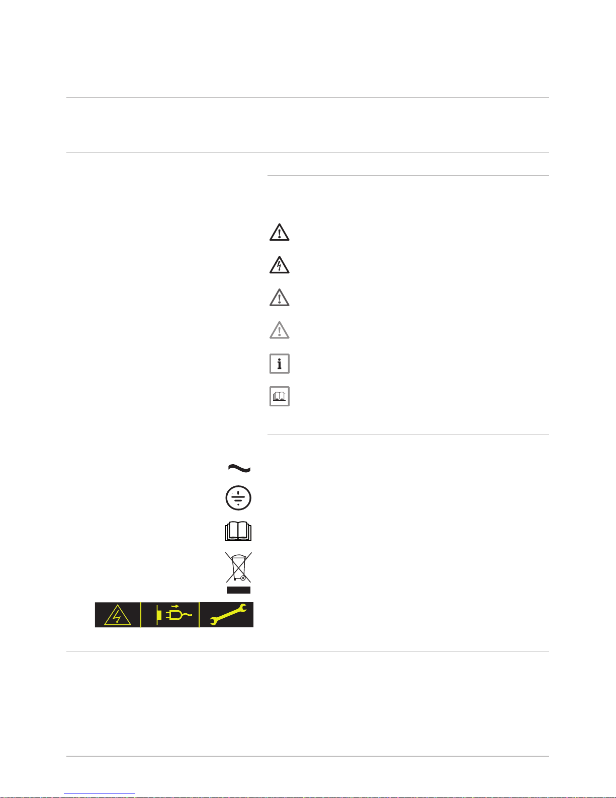
2.2.2 Symbols used on the appliance
1 Alternating current.
2 Protective earthing.
3 Before installing and commissioning the appliance, carefully read
the instruction manuals provided.
4 Dispose of used products through an appropriate recovery and
recycling structure.
5 Caution: danger of electric shock, live parts. Disconnect the mains
power prior to carrying out any work.
2.3 Abbreviations/Glossary
COP Coefficient of performance
EER Energy efficiency ratio
PCU PCB for managing burner operation
SU Safety PCB
Fig.1 Symbols used on the appliance
1 2
MW-2000068-1
1
2
3
4
5
2 About this manual
7612035 - v02 - 12062014 AWHP-2 MIV-3 V220 7
Page 8
3 Technical specifications
3.1 Heat pump
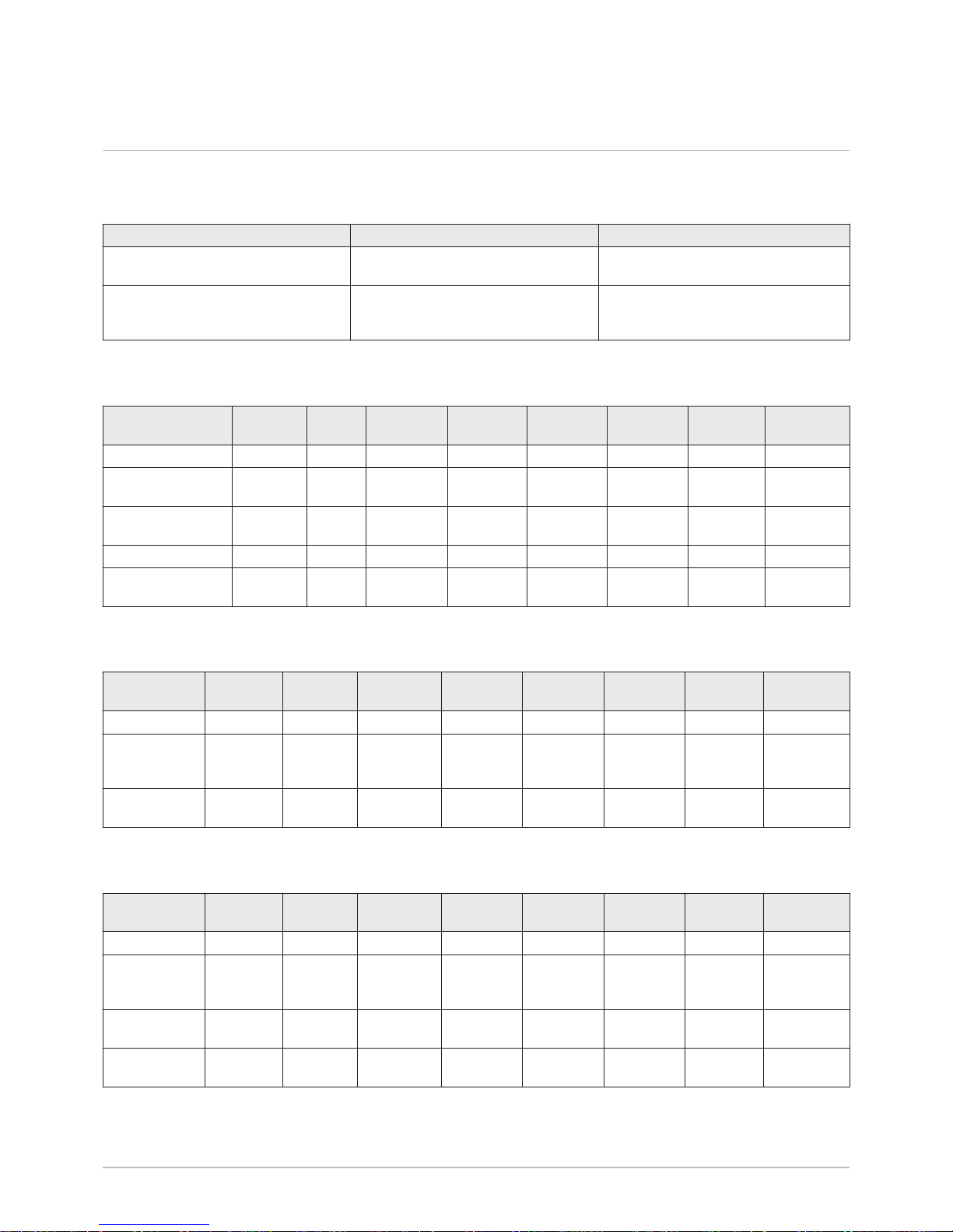
Maximum operating pressure: 3 bar
Tab.1 Conditions of use
Water (°C) Outside air (°C)
Limit operating temperatures in Hot
mode
+18 / +60 AWHP 4 MR, AWHP 6 MR-2: -15 / +35
Other models: -20 / +35
Limit operating temperatures in Cooling
mode (MIV-3/EM V220 – MIV-3/ET V220
– MIV-3/H 4-8 V220)
+18 / +25 +7 / +40
Tab.2 Hot mode: outside air temperature +7°C, outlet water temperature +35°C. Performances in accordance with EN
14511-2.
Measurement type Unit AWHP
4 MR
AWHP 6
MR-2
AWHP 8
MR-2
AWHP 11
MR-2
AWHP 11
TR-2
AWHP 16
MR-2
AWHP 16
TR-2
Calorific output kW 3.94 5.73 8.26 11.39 11.39 14.65 14.65
Coefficient of
Performance (COP)
4.53 4.04 4.27 4.65 4.65 4.22 4.22
Absorbed electrical
power
kWe 0.87 1.42 1.93 2.45 2.45 3.47 3.47
Nominal amperage A 4.11 6.57 8.99 11.41 3.8 16.17 5.39
Nominal water flow
rate (ΔT = 5K)
m3/hour
0.68 0.99 1.42 1.96 1.96 2.53 2.53
Tab.3 Hot mode: outside air temperature +2 °C, outlet water temperature +35°C. Performances in accordance with EN
14511-2.
Measurement
type
Unit AWHP 4 MRAWHP 6
MR-2
AWHP 8
MR-2
AWHP 11
MR-2
AWHP 11
TR-2
AWHP 16
MR-2
AWHP 16
TR-2
Calorific output kW 3.76 3.19 5.30 10.19 10.19 12.90 12.90
Coefficient of
Performance
(COP)
3.32 2.97 3.46 3.20 3.20 3.27 3.27
Absorbed
electrical power
kWe 1.13 1.08 1.53 3.19 3.19 3.94 3.94
Tab.4 Cold mode: outside air temperature +35°C, outlet water temperature +18°C. Performances in accordance with EN
14511-2.
Measurement
type
Unit AWHP 4 MRAWHP 6
MR-2
AWHP 8
MR-2
AWHP 11
MR-2
AWHP 11
TR-2
AWHP 16
MR-2
AWHP 16
TR-2
Cooling output kW 3.84 4.69 7.90 11.16 11.16 14.46 14.46
Energy
efficiency ratio
(EER)
4.83 4.09 3.99 4.75 4.75 3.96 3.96
Absorbed
electrical power
kWe 0.72 1.15 2.00 2.35 2.35 3.65 3.65
Nominal
amperage
A 3.40 5.43 9.40 11.05 3.68 17.15 5.71
3 Technical specifications
8 AWHP-2 MIV-3 V220 7612035 - v02 - 12062014
Page 9
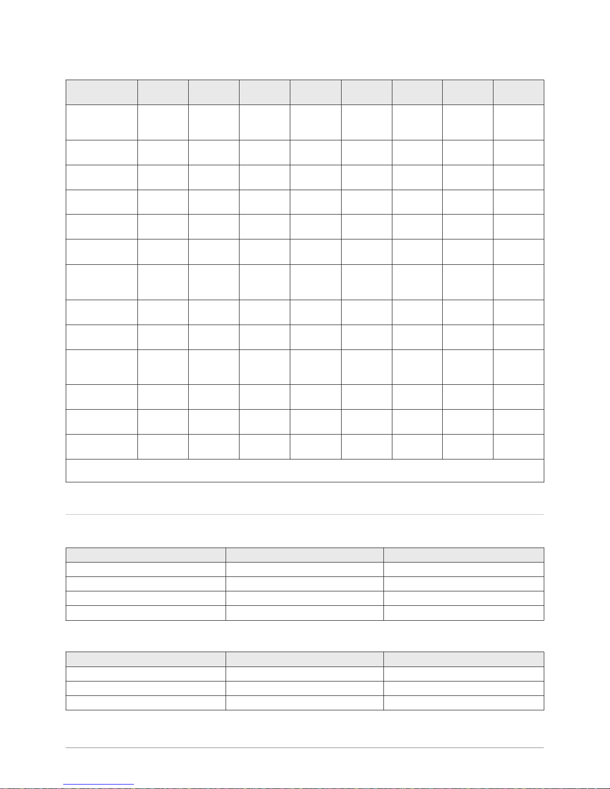
Tab.5 Common specifications
Measurement
type
Unit AWHP 4 MRAWHP 6
MR-2
AWHP 8
MR-2
AWHP 11
MR-2
AWHP 11
TR-2
AWHP 16
MR-2
AWHP 16
TR-2
Total dynamic
head at nominal
flow rate
kPa 58 49 29 11 11 35 35
Nominal air flow
rate
m3/hour
2100 2100 3300 6000 6000 6000 6000
Power voltage of
the outdoor unit
V 230 230 230 230 400 230 400
Start-up
amperage
A 5 5 5 5 3 6 3
Maximal
amperage
A 13 13 19 29.5 13 29.5 13
Acoustic power Inside
(1)
dB(A) 52.9 52.9 53.3 53.3 53.3 53.3 53.3
Acoustic power Outside
(1)
dB(A) 62.4 64.8 65.2 68.8 68.8 68.5 68.5
Acoustic
pressure
(2)
dB(A) 41.7 41.7 43.2 43.4 43.4 47.4 47.4
Refrigerant fluid
R410A
kg 2.1 2.1 3.2 4.6 4.6 4.6 4.6
Refrigeration
connection
(Liquid/Gas)
inch 1/4 - 1/2 1/4 - 1/2 3/8 – 5/8 3/8 – 5/8 3/8 – 5/8 3/8 – 5/8 3/8 – 5/8
Max. pre-loaded
length
m 10 10 10 10 10 10 10
Weight (empty) Outdoor unit
kg 42 42 75 118 130 118 130
Weight (empty) Indoor module
kg 52 52 52 55 55 55 55
(1) Noise radiated by the envelope - Test run in accordance with the NF EN 12102 standard, temperature conditions: air 7°C, water 55°C
(2) at 5 m from the appliance, free field
3.2 Domestic hot water tanks
Tab.6 Technical specifications primary circuit (heating water)
Specification Unit Value
Maximum operating temperature °C 85
Maximum operating pressure bar (MPa) 3 (0.3)
Exchanger capacity Litres 14
Exchange surface m² 1.7
Tab.7 Technical specifications secondary circuit (domestic water)
Specification Unit Value
Maximum operating temperature °C 70
Maximum operating pressure bar (MPa) 10 (1.0)
Water capacity Litres 220
3 Technical specifications
7612035 - v02 - 12062014 AWHP-2 MIV-3 V220 9
Page 10
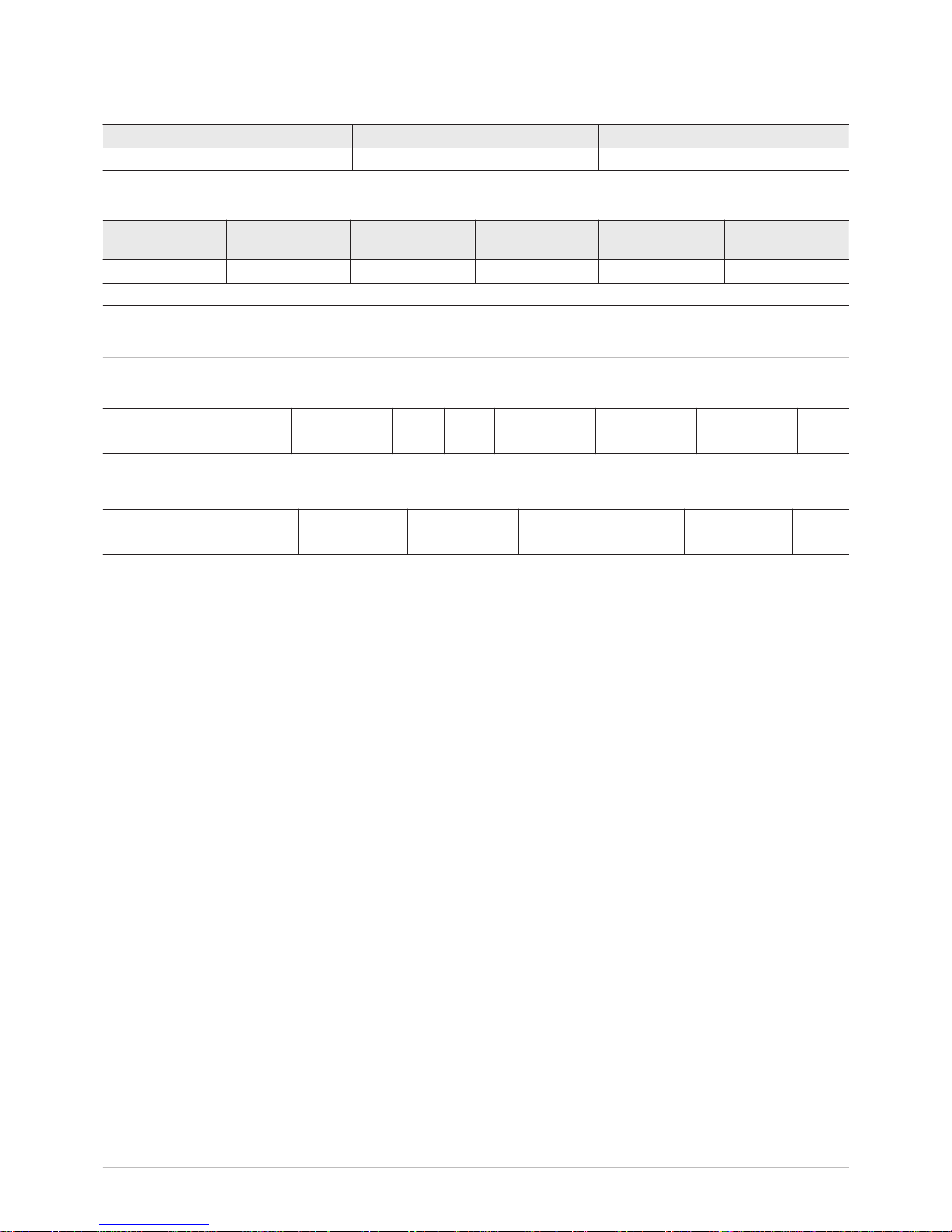
Tab.8 Weight
Specification Unit Value
Shipping weight kg 112
Tab.9 Domestic hot water tank loading time
AWHP/AWHPV220
AWHP 4 MR AWHP 6 MR-2 AWHP 8 MR-2 AWHP 11 MR-2
AWHP 11 TR-2
AWHP 16 MR-2
AWHP 16 TR-2
Loading time
(1)
4 hours 50 minutes 3 hours 15 minutes 2 hours 25 minutes 1 hours 40 minutes 1 hours 15 minutes
(1) ΔT = 55K. Outside temperature: 7°C. Inside air temperature: 20°C
3.3 Sensor characteristics
Tab.10 Outside temperature sensor
Temperature in °C -20 -16 -12 -8 -4 0 4 8 12 16 20 24
Resistance in Ω 2392 2088 1811 1562 1342 1149 984 842 720 616 528 454
Tab.11 Domestic hot water sensor, flow sensor
Temperature in °C 0 10 20 25 30 40 50 60 70 80 90
Resistance in Ω 32014 19691 12474 10000 8080 5372 3661 2535 1794 1290 941
3 Technical specifications
10 AWHP-2 MIV-3 V220 7612035 - v02 - 12062014
Page 11

4 Description of the product
4.1 General description
The ALEZIO V220 EVOLUTION heat pump is composed of:
A reversible outside module for energy production in Hot or Cold mode.
An inside module with a control panel to handle the thermal exchange
between the R410A fluid and the hydraulic circuit.
Both units are connected by means of refrigeration and electrical
connections. The inside module handles domestic hot water production.
The system offers the following advantages:
The heating circuit is housed in the insulated volume within the home.
Thanks to the DC inverter, the heat pump modulates its output to adapt
to the needs of the home.
The control panel uses the outside sensor to adjust the temperature of
the heating circuit according to the outside temperature.
The steel domestic hot water tank is lined with food quality standard
enamel vitrified at 850°C, which protects the tank from corrosion.
The heat exchanger in the domestic hot water tank is a coil welded
inside the tank, made of smooth piping. Its external surface, which
comes into contact with drinking water, is enamelled.
The appliance is insulated by Chlorofluorocarbon-free polyurethane
foam, which helps to reduce heat losses to a minimum.
The outside casing is made of painted steel sheeting.
The tank is protected against corrosion by a magnesium anode.
4.2 Operating principle
4.2.1 Hybrid operating mode
Note
The hybrid operating mode is only available for appliances with
hydraulic back-up.
The appliance offers a choice between several hybrid operating modes.
The modes available offer either optimised energy consumption according
to energy cost, or optimised energy consumption according to primary
energy consumption. Both hybrid operating modes are available via the
parameter .
In optimised primary energy consumption mode, the control system
chooses the generator that consumes the least primary energy.
In optimised energy cost mode, the control system chooses the
cheapest generator according to the coefficient of performance of the
heat pump and according to energy cost.
4 Description of the product
7612035 - v02 - 12062014 AWHP-2 MIV-3 V220 11
Page 12

4.3 Control panel description
4.3.1 Description of the keys
Fig.2 Control panel
-
)
m
w
r
r
r
d
d
v
c
d
SERVICE
MW-L000308-1
h
j
1 2 3 4
1 Escape key
2 Heating temperature key or
3 Domestic hot water temperature key or
4 [Enter] key
4.3.2 Description of the display
h
Back to the previous level without saving the modifications made
Access to the "heating set point temperature" parameter
To reduce a value
Access to the "domestic hot water set point temperature"
parameter
To increase a value
Confirmation of the value displayed or access to the menu selected
User menu
Information menu
Installer menu
Fig.3 Key functions
-
m
r
r
ddd
SERVICE
MW-L000309-1
h
j
w
r
v
c
)
Fig.4 Menus
-
m
r
d d
SERVICE
MW-L000310-1
w
r
v
c
)
4 Description of the product
12 AWHP-2 MIV-3 V220 7612035 - v02 - 12062014
Page 13

A manual vent cycle is running
Permanent display of the Information menu
The screed drying function is active
Shut-down/Frost Protection mode
Compressor on
Electrical or hydraulic back-up running
Cooling mode on
Domestic hot water mode active
Central heating off
Fault active
Manual mode
Heating back-up
Domestic hot water back-up
Fig.5 Operating indicators
m
r
d
d
SERVICE
MW-L000311-2
w
r
v
c
Fig.6 Forcing back-up
m
r
d
MW-L000312-1
r
4 Description of the product
7612035 - v02 - 12062014 AWHP-2 MIV-3 V220 13
Page 14

5 Operation
5.1 Using the control panel
The various menus can be accessed using various key combinations.
1. Simultaneously press the C ( ) and D keys. The symbol flashes.
2. Use the B ( ) and C ( ) keys to scroll through the menus.
3. Confirm by pressing the D ( ) key.
Note
Press the A (h) key to go back to the main display.
If no keys are pressed for 10 seconds, the screen goes back to
the main display without saving the parameters.
5.2 Starting the heat pump
Caution
Only qualified professionals may carry out initial commissioning or
a start-up when the heat pump has completely stopped.
When the appliance is switched on, the control panel indicates its
operating mode:
Screen display Operating mode
Heating and domestic hot water
Swimming pool and domestic hot water
Heating
Swimming pool
+ Domestic Hot Water
+ Cooling and domestic hot water
Cooling
Shutdown/Frost Protection
See
Changing the operating mode, page 18.
5.3 Switching off the central heating
It is possible to shut down the central heating and select an operating
mode suited to the situation and the desired comfort level:
In summer, for the sake of comfort, it is possible to operate cooling
(only for the reversible versions).
Fig.7 Accessing the menus
-
m
r
r
ddd
SERVICE
MW-L000313-1
A B C D
w
r
v
c
h
j
)
Fig.8 Scrolling through the menus
)
-
m
r
r
ddd
SERVICE
MW-L000314-1
A B C D
w
r
v
c
h
j
5 Operation
14 AWHP-2 MIV-3 V220 7612035 - v02 - 12062014
Page 15

In the event of a prolonged absence (weekend, holiday), it is possible to
switch to shutdown/frost protection mode.
It is possible to produce domestic hot water all year round.
See
User settings, page 17
Caution
It is recommended that the heat pump never be completely shut
down. Frost protection is no longer automatically guaranteed if the
mains supply is switched off.
5.4 Frost Protection
When the outside temperature drops too low, the appliance's protection
system starts up. Frost protection is handled by the back-up. The back-up
is tripped automatically to handle frost protection under the following
conditions:
Tab.12 Frost protection conditions
Frost protection Conditions
Heating circuit Outside temperature: < 3°C
Heating flow temperature: < 6°C
Domestic hot water
tank protection
Outside temperature: < 3°C
Domestic hot water temperature: < 4°C
5 Operation
7612035 - v02 - 12062014 AWHP-2 MIV-3 V220 15
Page 16

6 Settings
6.1 List of parameters
6.1.1 Choosing the hybrid operating mode
Parameter Description Adjustment range Increment Factory
setting
(1)
Hybrid operating mode 0 to 2
0 = Deactivated
1 = Optimisation of primary energy
consumption
2 = Optimisation according to energy cost
1 0
(1) Only available if = 0
Note
It is imperative that you input the energy cost parameters ,
and to use the hybrid operating mode optimised according
to energy cost
6.1.2 Energy cost parameters
Caution
The currency for parameters , and must be the
same. Example: in euro per kWh and in euro per litre.
Note
Parameters , and are available only if = 2.
Tab.13 Energy cost parameter
Parameter Description Adjustment
range
Increment Factory setting
(1)
Tariff per kWh of electricity
For a standard electricity tariff, input the
parameter .
0.01 to 2.00 0.01 0.13
(1)
.
Tariff per kWh of electricity (off-peak hours).
For a Peak Hours / Off-peak Hours electricity
tariff, input the parameters for the Peak
Hours tariff and for the Off-peak Hours tariff.
0.01 to 2.00 0.01 0.09
(1)
.
Fossil energy tariff for the hydraulic back-up
Gas boiler: Tariff per m3 of gas. Example: €/m
3
Oil boiler: Tariff per litre of oil. Example: €/litre
0.01 to 2.50 0.01 0.9
(1) Only available if = 0
6 Settings
16 AWHP-2 MIV-3 V220 7612035 - v02 - 12062014
Page 17

6.2 User settings
Note
If no keys are pressed, the settings menus are exited
automatically after 10 seconds without saving the parameters.
6.2.1 Modifying the room temperature set point
1. Press the B ( ) key.
2. Use the B ( ) or C key ( ) to modify the value.
Tab.14 Room temperature set point parameter
Temperature Adjustment
range
Increment Factory setting
Room
temperature
set point
from 15 to 30 °C1 °C 20°C
3. Press the D ( ) key to confirm and exit the menu.
Note
When a room thermostat is connected, set it to a value 2 K higher
than the room temperature set point .
6.2.2 Modifying the domestic hot water temperature
1. Press the C ( ) key.
2. Use the B ( ) or C key ( ) to modify the value.
Temperature Adjustment
range
Increment Factory
setting
DHW set point
temperature
from 40 to
65°C
1 °C 50 °C
3. Press the D ( ) key to confirm and exit the menu.
Fig.9 Press the B key.
)
-
m
r
r
ddd
SERVICE
L000317-A
A C D
w
r
v
c
h
j
B
Fig.10 Modifying the value
)
-
m
r
r
ddd
SERVICE
L000318-A
A B C D
w
r
v
c
h
j
Fig.11 Press the C key.
)
-
m
r
r
ddd
SERVICE
L000319-A
A C D
w
r
v
c
h
j
B
Fig.12 Modifying the value
)
-
m
r
r
ddd
SERVICE
L000320-A
A B C D
w
r
v
c
h
j
6 Settings
7612035 - v02 - 12062014 AWHP-2 MIV-3 V220 17
Page 18

6.2.3 Changing the operating mode
1. Press keys C ( ) and (D) simultaneously.
The symbol flashes.
2. Confirm by pressing the D ( ) key.
3. Use the B ( ) or C key ( ) to modify the value.
Operating mode Value Screen display
Heating and domestic hot
water
1
Heating 2
Domestic Hot Water 3 +
Cooling and domestic hot
water
4 +
Cooling 5
Shut-down/Frost Protection 6
Swimming pool 7
Swimming pool and domestic
hot water
8
4. Press the D key ( ) to confirm and exit the menu.
6.2.4 Configuring the hybrid operating mode
1. Go to the Installer menu.
See
Using the control panel, page 14.
2. Use the and keys to switch from one parameter to another.
See
List of parameters, page 16.
3. Use the and keys to modify the parameter value.
4. Press the key to confirm the setting.
Note
To modify another parameter, repeat the procedure from step 3.
5. Press the h key to exit the menu.
6.2.5 Forcing use of the back-up
Note
It is impossible to force the back-up when the shut-down/frost
protection mode is selected.
It is possible to force use of the back-up to complement the heat pump. To
force use of the back-up, perform the following operations:
1. Press the A and D keys simultaneously. Hold the keys down.
Fig.13 Modifying the value
)
-
m
r
r
ddd
SERVICE
L000322-A
A B C D
w
r
v
c
h
j
Fig.14 Navigating in the menu
)
-
m
r
r
ddd
SERVICE
MW-C004252-1
A B C D
w
r
v
c
h
j
Fig.15 Accessing the forcing function
)
-
m
r
r
ddd
SERVICE
L000323-A
A C D
w
r
v
c
h
j
B
6 Settings
18 AWHP-2 MIV-3 V220 7612035 - v02 - 12062014
Page 19

2. Hold the A key down and press the D key successively to choose
the forcing desired.
Display Back-up
+ Forcing the back-up for heating
+ Forcing the back-up for
domestic hot water
+ + Forcing the back-up for heating
and domestic hot water
The symbol disappears from
the display.
Back-up forcing deactivated
6.3 Reading out measured values
6.3.1 Displaying the measured values
1. Go to the Information menu ( ).
See
Using the control panel, page 14.
2. Use the B ( ) and C ( ) keys to scroll through the information.
Note
If no keys are pressed for 10 seconds, the screen goes back to
the main display. For permanent information display: When the
wording flashes, press the A (h) and B ( ) keys
simultaneously.
The wording continues to be displayed and stops flashing.
3. Press the A (h) key to exit the menu.
Note
If the wording is not displayed, the screen will switch back
to the main display after 5 seconds.
Information menu
Parameter Description Unit
In heating mode: Heating flow set point temperature
In domestic hot water mode: DHW set point temperature
In cooling mode: Cooling set point temperature
In swimming pool mode: Swimming pool set point temperature
°C
Measured flow temperature °C
Measured domestic hot water temperature °C
Measured outside temperature °C
Water flow rate litres/minute
Software version
6.3.2 Energy consumption display
Note
The energy consumption display is done after the information
menu .
Tab.15
Parameter Description Unit
Estimated electrical energy consumption in heating mode
(1)
kWh
Estimated electrical energy consumption in domestic hot water mode
(1)
.
kWh
Fig.16 Selecting the forcing desired
)
-
m
r
r
ddd
SERVICE
L000324-A
A C D
w
r
v
c
h
j
B
Fig.17 Information menu
)
-
m
r
r
ddd
SERVICE
MW-L000315-1
A B C D
w
r
v
c
h
j
6 Settings
7612035 - v02 - 12062014 AWHP-2 MIV-3 V220 19
Page 20

Parameter Description Unit
Estimated electrical energy consumption in cooling mode
(1)(2)
.
kWh
(1) Display available if the estimated electrical energy consumption function is activated
(2) Cooling mode must be enabled.
The estimated electricity consumption is displayed in 3 digits. The first digit
indicates the scale (x1, x10, x100, x1000).
Tab.16 Examples of energy consumption displays
Display example Description
Fig.18 Unit 1 kWh
)
-
m
r
r
ddd
SERVICE
MW-C004248-1
A B C D
w
r
v
c
h
j
The displayed value is 123 kWh. The unit is 1 kWh.
Fig.19 Unit 10 kWh
)
-
m
r
r
ddd
SERVICE
MW-C004249-1
A B C D
w
r
v
c
h
j
The displayed value is 1230 kWh. The unit is 10 kWh. The first digit
indicates the scale x 10. Only the first 3 digits are displayed.
Fig.20 Unit 100 kWh
)
-
m
r
r
ddd
SERVICE
MW-C004250-1
A B C D
w
r
v
c
h
j
The displayed value is 12300 kWh. The unit is 100 kWh. The first
digit indicates the scale x 100. Only the first 3 digits are displayed.
6 Settings
20 AWHP-2 MIV-3 V220 7612035 - v02 - 12062014
Page 21

Display example Description
Fig.21 Unit 1000 kWh
)
-
m
r
r
ddd
SERVICE
MW-C004251-1
A B C D
w
r
v
c
h
j
The displayed value is 123000 kWh. The unit is 1000 kWh. The first
digit indicates the scale x 1000. Only the first 3 digits are displayed.
6 Settings
7612035 - v02 - 12062014 AWHP-2 MIV-3 V220 21
Page 22

7 Maintenance
7.1 General instructions
Maintenance operations are important for the following reasons:
To guarantee optimum performance.
To extend the life of the equipment.
To provide an installation which offers the customer optimum comfort
over time.
Caution
An annual service of the heat pump is mandatory.
7.2 Maintenance instructions
1. Check the hydraulic pressure in the installation.
Note
If the water pressure is lower than 1 bar, more water should be
added. If necessary, top up the water level in the heating system
(recommended hydraulic pressure between 1.5 and 2.0 bar, or
between 0.15 and 0.2 MPa)..
See
Top up the installation with water, page 22.
2. Carry out a visual check for any water leaks.
3. Open and close the radiator valves several times a year.
This helps to prevent the valves from seizing up.
4. Clean the outside of the heat pump using a damp cloth and a mild
detergent.
Caution
Only qualified professionals are permitted to clean the inside of
the heat pump.
7.3 Top up the installation with water
If necessary, top up the water level in the heating system (recommended
hydraulic pressure between 1.5 and 2 bar (0.15 and 0.2 MPa)).
1. Open the valves on all radiators connected to the heating system.
2. Set the room thermostat to as low a temperature as possible.
3. Put the heat pump in shut-down/frost protection mode.
See
User settings, page 17.
4. Open the fill valve.
5. Close the fill valve when the pressure gauge shows a pressure of
1.5 bar (0.15 MPa).
6. Put the heat pump in heating mode.
See
User settings, page 17.
7. When the pump has stopped, vent again and top up the water
pressure.
Fig.22 Beware of water leaks
AD-0001507-A
Fig.23 Opening/closing the radiator valves
AD-0000181-A
1
2
3
4
Fig.24 Opening/closing the radiator valves
AD-0000181-A
1
2
3
4
7 Maintenance
22 AWHP-2 MIV-3 V220 7612035 - v02 - 12062014
Page 23

Note
Filling and venting the installation twice a year should be sufficient
to obtain an adequate hydraulic pressure. If it is often necessary
to top up the installation with water, contact your installer.
7.4 Venting the heating system
It is essential that you vent any air in the domestic hot water tank, the
pipes and the taps to prevent the annoying noises likely to be produced
during heating or when drawing off water.
7.4.1 Manual venting
1. Open the valves on all radiators connected to the heating system.
2. Put the heat pump in shut-down/frost protection mode.
3. Vent the underfloor heating circuits and the radiators. First vent the
lower floors A and then the upper floors B.
Note
The heating pump stops 5 minutes after selection of the shutdown/frost protection mode. If the outside temperature is lower
than 3°C, the heating pump continues to run.
7.4.2 Automatic venting
If the parameter is set to 0, the heat pump runs an automatic
venting cycle when it is switched on.
If the parameter is set to 1, a domestic hot water tank is connected.
Automatic venting starts up only if the measured domestic hot water
temperature is lower than 25°C.
Automatic venting takes approximately one minute. It is possible to
manually extend automatic venting to more than one minute.
1. When powering up, the word flashes. Press the A and B keys
( ) simultaneously. An automatic venting cycle begins. The word
stops flashing.
2. Press the A and B keys ( ) simultaneously to stop the venting
cycle.
Caution
After venting, check whether the pressure in the installation is still
sufficient. Add more water to the installation if necessary.
Fig.25 Opening the radiators
AD-0000181-A
1
2
3
4
Fig.26 Venting the floors
MW-M001495-1
AA
BB
Fig.27 Powering up
7 Maintenance
7612035 - v02 - 12062014 AWHP-2 MIV-3 V220 23
Page 24

8 Troubleshooting
8.1 Error codes
In the event of problems, the control panel displays the symbol and an
error code.
Caution
Make a note of the code displayed.
The error code is important for the correct and rapid diagnosis of
the type of malfunction and for any technical assistance from your
installer.
To go back to the main display, press the key.
The symbol continues to be displayed as long as the error is present.
Navigation is possible in all menus.
Error code Description Probable causes Checking / solution
Configuration error The control system mode is not
compatible with the configuration
of the installer parameters.
Contact the installer.
Flow sensor error.
The heat pump stops
and no control system
modes are available.
Bad connection
Sensor failure
Contact the installer.
Outside temperature
sensor error.
The control system
switches to downgraded
mode with a default
outside temperature of
-20°C.
Bad connection
Sensor failure
Contact the installer.
Domestic hot water
sensor error.
Production of domestic
hot water is stopped
Bad connection
Sensor failure
Contact the installer.
Flow rate error The water pressure is too low
Heating water flow rate too low
Close the isolation valves and check
the water pressure with the pressure
gauge.
Too much air Completely vent the indoor module
and the installation for optimum
running.
Error on the outdoor unit. Error on the outdoor unit. Contact the installer.
8 Troubleshooting
24 AWHP-2 MIV-3 V220 7612035 - v02 - 12062014
Page 25

8.2 Incidents and solutions
Problems Probable causes Corrections
The radiators are cold. The heating set point
temperature is too low.
Increase the value of parameter or, if a room thermostat is
connected, increase the temperature on it.
See
User settings, page 17.
The heating mode is
deactivated.
Activate the heating mode.
See
User settings, page 17.
The radiator valves are
closed.
Open the valves on all radiators connected to the heating system.
The heat pump is not
operating.
Check that the heat pump is switched on.
Check the fuses and switches on the electrical installation.
The water pressure is too
low (< 1 bar).
Top up the installation with water.
See
Top up the installation with water, page 22.
There is no domestic
hot water.
The domestic hot water
set point temperature is
too low.
Increase the value of parameter .
See
User settings, page 17.
The domestic hot water
mode is deactivated.
Activate the domestic hot water mode.
See
User settings, page 17.
The energy-saving shower
head is restricting the
water flow.
Clean the shower head; replace it if necessary.
The heat pump is not
operating.
Check that the heat pump is switched on.
Check the fuses and switches on the electrical installation.
The water pressure is too
low (< 1 bar).
Top up the installation with water.
See
Top up the installation with water, page 22.
Significant variations in
domestic hot water
temperature
Insufficient water supply Check the water pressure in the installation.
Open the valve.
The heat pump does
not work.
The heating set point
temperature is too low.
Increase the value of parameter or, if a room thermostat is
connected, increase the temperature on it.
See
User settings, page 17.
The heat pump is not
operating.
Check that the boiler is switched on.
Check the fuses and switches on the electrical installation.
The water pressure is too
low (< 1 bar).
Top up the installation with water.
See
Top up the installation with water, page 22.
An error code appears on
the display.
Correct the error if possible.
See
Error codes, page 24.
8 Troubleshooting
7612035 - v02 - 12062014 AWHP-2 MIV-3 V220 25
Page 26

Problems Probable causes Corrections
The water pressure is
too low (< 1 bar).
Not enough water in the
installation.
Top up the installation with water.
See
Top up the installation with water, page 22.
Water leak. Contact the installer.
Clicking in the central
heating pipes
.
The central heating pipe
clamps are too tight.
Contact the installer.
There is air in the heating
pipes.
It is essential that you vent any air in the domestic hot water tank, the
pipes and the taps to prevent the annoying noises likely to be produced
during heating or when drawing off water.
See
Venting the heating system, page 23.
The water is circulating too
quickly in the central
heating system.
Contact the installer.
Significant water leak
underneath or in the
vicinity of the heat
pump.
The pipes on the heat
pump or the central
heating are damaged.
Contact the installer.
8 Troubleshooting
26 AWHP-2 MIV-3 V220 7612035 - v02 - 12062014
Page 27

9 Decommissioning procedure
To decommission the heat pump temporarily or permanently:
1. Contact the installer.
Fig.28 Cutting the mains supply
AD-0000155-A
9 Decommissioning procedure
7612035 - v02 - 12062014 AWHP-2 MIV-3 V220 27
Page 28

10 Environmental
10.1 Energy savings
Tips on saving energy:
Do not block ventilation outlets.
Do not cover the radiators. Do not hang curtains in front of the radiators.
Install reflective panels behind the radiators to prevent heat losses.
Insulate the pipes in rooms that are not heated (cellars and lofts).
Turn off the radiators in rooms not being used.
Do not run hot (or cold) water pointlessly.
Install a water-saving shower head to save up to 40% energy.
Take showers rather than baths. A bath consumes twice as much water
and energy.
10.2 Room thermostat and settings
Various models of room thermostat are available. The type of thermostat
used and the parameter selected impact total energy consumption.
A modulating regulator, which may be combined with thermostatic
valves, is eco-friendly in terms of energy and offers an excellent level of
comfort. This combination allows you to set the temperature separately
for each room. However, do not install thermostatic radiator valves in the
room in which the room thermostat is located.
Complete opening and closing of the thermostatic radiator valves
causes undesirable variations in temperature. Therefore, these must be
opened/closed progressively.
Set the room thermostat to a temperature of approximately 20°C to
reduce heating costs and energy consumption.
Lower the thermostat setting to approximately 16°C at night or when you
are not at home. This reduces heating costs and energy consumption.
Lower the thermostat setting well before airing the rooms.
Set the water temperature to a lower level in summer than in winter (e.g.
60°C and 80°C respectively) when an ON/OFF thermostat
is used.
When clock thermostats and programmable thermostats are to be set,
do not forget to take any holidays and days when no one is at home into
account.
10 Environmental
28 AWHP-2 MIV-3 V220 7612035 - v02 - 12062014
Page 29

11 Warranty
11.1 General
We would like to thank you for buying one of our appliances and for your
trust in our product.
In order to ensure continued safe and efficient operation we recommend
that the product is regularly inspected and maintained.
Your installer and our service department can assist with this.
11.2 Terms of warranty
This appliance comes with a warranty that covers all manufacturing faults;
the warranty period will commence on the date of purchase stated on the
installer's invoice.
The warranty period is stated in our price list.
As a manufacturer, we can by no means be held liable if the appliance is
used incorrectly, is poorly maintained or not maintained at all, or is not
installed correctly (it is your responsibility to ensure that installation is
carried out by a qualified installer).
In particular, we cannot be held liable for material damage, intangible
losses or physical injury resulting from an installation that does not comply
with:
Legal or regulatory requirements or provisions laid down by the local
authorities
National or local regulations and special provisions relating to the
installation
Our manuals and installation instructions, in particular in terms of regular
maintenance of the appliances.
Our warranty is limited to the replacement or repair of the parts found to
be defective by our technical services team, excluding labour, transfer and
transport costs.
Our warranty does not cover replacement or repair costs for parts that may
become defective due to normal wear, incorrect usage, the intervention of
unqualified third parties, inadequate or insufficient supervision or
maintenance, a mains supply that is not appropriate or the use of
unsuitable or poor quality fuel.
The warranty is only valid for smaller parts, such as motors, pumps,
electrical valves etc., if these parts have never been dismantled.
The rights stated in European Directive 99/44/EEC, implemented by legal
decree no. 24 dated 2 February 2002 and published in Government
Gazette no. 57 dated 8 March 2002, remain in force.
11 Warranty
7612035 - v02 - 12062014 AWHP-2 MIV-3 V220 29
Page 30

12 Appendix
12.1 Declaration of Conformity
Fig.29 Declaration of Conformity
MW-C004792-1
12 Appendix
30 AWHP-2 MIV-3 V220 7612035 - v02 - 12062014
Page 31

© Copyright
All technical and technological information contained in these technical instructions, as well as any drawings and technical
descriptions supplied, remain our property and shall not be multiplied without our prior consent in writing. Subject to alterations.
Page 32

DE DIETRICH THERMIQUE
57, rue de la Gare F- 67580 MERTZWILLER - BP 30
MW-8000005-5
DUEDI S.r.l.
DE DIETRICH SERVICE
BDR Thermea (Czech republic) s.r.o
www.duediclima.it
www.dedietrich.cz
Distributore Ufficiale Esclusivo
De Dietrich-Thermique Italia
www.dedietrich-heiztechnik.com
Freecall 0800 / 201608
Jeseniova 2770/56
130 00 Praha 3
+49 (0)25 72 / 9161-0
+49 (0)25 72 / 9161-102
info@remeha.de
Via Passatore, 12 - 12010
San Defendente di Cervasca
CUNEO
+39 0171 857170
+39 0171 687875
info@duediclima.it
+420 271 001 627
info@dedietrich.cz
IT
DE DIETRICH THERMIQUE Iberia S.L.U.
www.dedietrich-calefaccion.es
C/Salvador Espriu, 11
08908 L’HOSPITALET de LLOBREGAT
+34 935 475 850
info@dedietrich-calefaccion.es
ES
129164, Россия, г. Москва
Зубарев переулок, д. 15/1
Бизнес-центр «Чайка Плаза»,
офис 309
+7 (495) 221-31-51
CZ
DE DIETRICH THERMIQUE S.A.S
7612035 - v02 - 12062014
7612035-001-02
 Loading...