

Page 1
ALEZIO
Reversible air / water heat pump "Split Inverter"
AWHP-V220
EN
User Guide
300026802-001-03
Page 2

Contents
1 Introduction ................................................................................................4
1.1 Symbols used .......................................................4
1.1.1 Symbols used in the manual ...................................4
1.1.2 Symbols used on the equipment .............................4
1.2 Abbreviations and lexicon ...................................5
1.3 General ..................................................................5
1.3.1 Manufacturer’s liability .............................................5
1.3.2 Installer’s liability .....................................................5
1.3.3 User’s liability ..........................................................6
2 Safety instructions and recommendations ..............................................7
2.1 Safety instructions ...............................................7
2.2 Recommendations ................................................7
3 Description ..................................................................................................9
3.1 General description ..............................................9
3.2 Main parts ..............................................................9
3.2.1 Inside module with electrical back-up .....................9
3.2.2 Inside module with hydraulic back-up ...................11
3.3 Control panel .......................................................12
3.3.1 Description of the keys ..........................................12
3.3.2 Description of the display ......................................12
3.3.3 Accessing the menus ............................................13
4 Operating the appliance ..........................................................................15
4.1 Starting the heat pump .......................................15
4.2 Shutting down the heat pump ...........................15
4.3 User settings .......................................................15
4.3.1
4.3.2 Modifying the domestic hot water
4.3.3 Changing the operating mode ...............................17
4.3.4 Forcing the additional heating ...............................17
4.3.5 Hybrid operating mode ..........................................18
Modifying the set room temperature d .................16
temperaturer .......................................................16
4.4 Reading out measured values ...........................19
4.4.1 Energy consumption display .................................20
1
23/04/2013 - 300026802-001-03
Page 3

Contents
5 Checking and maintenance .....................................................................22
5.1 General instructions ...........................................22
5.2 Periodic checks ..................................................22
5.3 Top up the installation with water .....................23
5.4 Bleeding the heating system .............................23
5.4.1 Manual venting ......................................................23
5.4.2 Automatic venting ..................................................24
6 Troubleshooting .......................................................................................25
6.1 Error codes ..........................................................25
6.2 Incidents and solutions ......................................26
7 Technical specifications ..........................................................................28
7.1 Technical specifications ....................................28
7.1.1 Heat pump .............................................................28
7.1.2 Domestic hot water tanks ......................................29
8 Energy savings .........................................................................................30
8.1 Energy savings ...................................................30
8.1.1 Energy-saving advice ............................................30
8.1.2 Room thermostat and settings ..............................30
9 Warranty ....................................................................................................31
9.1 General ................................................................31
9.2 Warranty terms ...................................................31
2
23/04/2013 - 300026802-001-03
Page 4

3
23/04/2013 - 300026802-001-03
Page 5
1 2
M002628-A
AWHP-V220
1 Introduction
1.1 Symbols used
1. Introduction
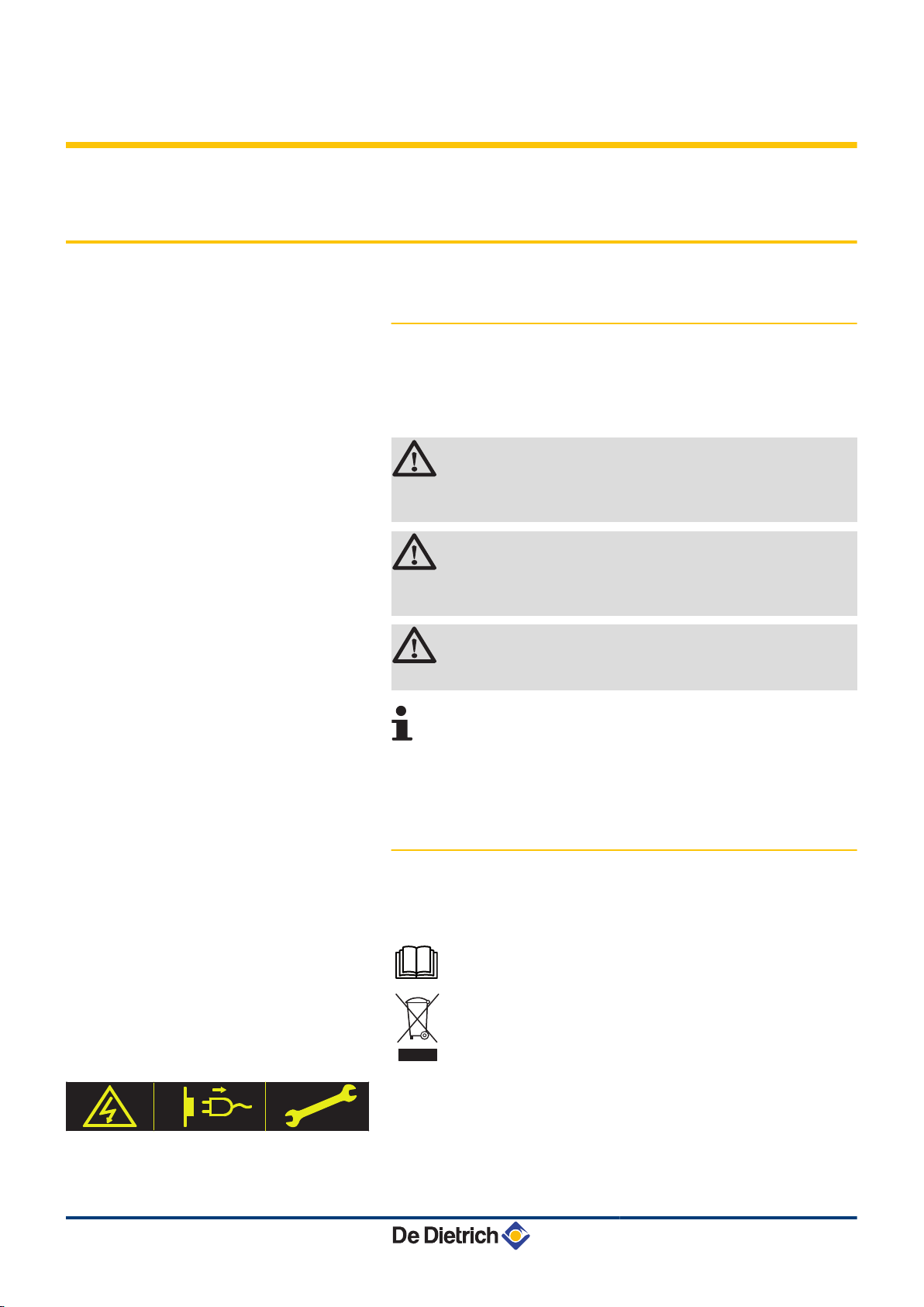
1.1.1. Symbols used in the manual
In these instructions, various danger levels are employed to draw the
user’s attention to particular information. In so doing, we wish to
safeguard the user’s safety, obviate hazards and guarantee correct
operation of the appliance.
DANGER
Risk of a dangerous situation causing serious physical
injury.
WARNING
Risk of a dangerous situation causing slight physical
injury.
CAUTION
Risk of material damage.
Signals important information.
¼Signals a referral to other instructions or other pages in the
instructions.
1.1.2. Symbols used on the equipment
4
~
Protective earthing
Alternating current
Before installing and commissioning the device, read
carefully the instruction manuals provided.
Dispose of the used products in an appropriate recovery
and recycling structure.
23/04/2013 - 300026802-001-03
Caution: danger, live parts.
Disconnect the mains power prior to any operations.
4
Page 6

1. Introduction
1.2 Abbreviations and lexicon
1.3 General
AWHP-V220
4 MIV: Indoor module
4 HP: Heat pump
4 DHW: Domestic hot water
4 Flow temperature: Temperature of the water circulating in the
radiators or in the underfloor heating
4 Ambient temperature: Temperature inside the house or in a room
4 Room temperature setpoint: Temperature programmed in the
control system that must be reached by the heat pump
4 Forced back-up operation: Function enabling the ignition of a
heating system to complement the heat pump in periods of
extreme cold
1.3.1. Manufacturer’s liability
Our products are manufactured in compliance with the requirements
of the various applicable European Directives. They are therefore
delivered with [ marking and all relevant documentation.
In the interest of customers, we are continuously endeavouring to
make improvements in product quality. All the specifications stated in
this document are therefore subject to change without notice.
It is our responsibility to inform customers, in accordance with Article
L. 113-3 of the Consumer Code, of their obligation to have this
equipment installed by a certified operator whenever the refrigerant
load is more than two kilograms or when a refrigerant connection is
necessary (the case with split systems, even when fitted with a quick
coupling device).
Our liability as the manufacturer may not be invoked in the following
cases:
4 Failure to abide by the instructions on using the appliance.
4 Faulty or insufficient maintenance of the appliance.
4 Failure to abide by the instructions on installing the appliance.
1.3.2. Installer’s liability
The installer is responsible for the installation and inital start up of the
appliance. The installer must respect the following instructions:
4 Read and follow the instructions given in the manuals provided
with the appliance.
4 Carry out installation in compliance with the prevailing legislation
and standards.
4 Perform the initial start up and carry out any checks necessary.
5
23/04/2013 - 300026802-001-03
Page 7

AWHP-V220 1. Introduction
4 Explain the installation to the user.
4 If a maintenance is necessary, warn the user of the obligation to
check the appliance and maintain it in good working order.
4 Give all the instruction manuals to the user.
1.3.3. User’s liability
To guarantee optimum operation of the appliance, the user must
respect the following instructions:
4 Read and follow the instructions given in the manuals provided
with the appliance.
4 Call on qualified professionals to carry out installation and initial
start up.
4 Get your installer to explain your installation to you.
4 Have the required checks and services done.
4 Keep the instruction manuals in good condition close to the
appliance.
This appliance is not intended to be used by persons (including
children) whose physcial, sensory or mental capacity is impaired or
persons with no experience or knowledge, unless they have the
benefit, through the intermediary of a person responsible for their
safety, of supervision or prior instructions regarding use of the
appliance. Care should be taken to ensure that children do not play
with the appliance.
To prevent hazardous situations from arising, if the mains lead is
damaged it must be replaced by the original manufacturer, the
manufacturer’s dealer or another suitably skilled person.
23/04/2013 - 300026802-001-03
6
Page 8
2. Safety instructions and recommendations
2 Safety instructions and
recommendations
2.1 Safety instructions
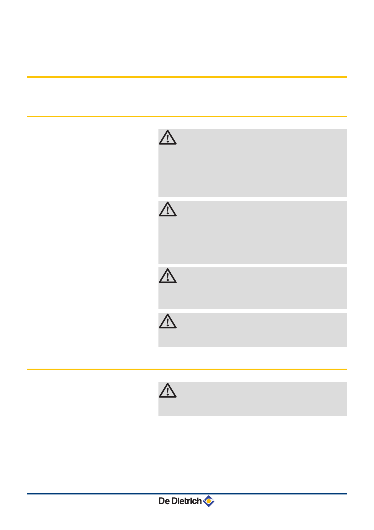
DANGER
If smoke is released or in case of refrigerant leak:
1. Switch the appliance off.
2. Open the windows.
3. Evacuate the premises.
4. Contact a qualified professional.
AWHP-V220
2.2 Recommendations
WARNING
Depending on the settings of the appliance:
4 The temperature of the radiators may reach 90°C.
4 Do not touch the refrigeration connection pipes with
your bare hands while the appliance is running.
Danger of burns or frost injury.
CAUTION
Do not neglect to service the appliance. Contact a qualified
professional or take out a maintenance contract for the
annual servicing of the appliance.
CAUTION
Before any work, switch off the mains supply to the
appliance.
WARNING
Only qualified professionals are authorised to work on the
appliance and the installation.
4 Have regular checks made to ensure that the water pressure in
the installation is between 1.5 and 2 bar.
4 Ensure that the appliance is accessible at all times for
maintenance purposes.
4 Avoid draining the installation.
4 Never remove or cover labels and rating plates affixed to the
appliance. Labels and rating plates must be legible throughout the
entire lifetime of the appliance.
7
23/04/2013 - 300026802-001-03
Page 9

AWHP-V220 2. Safety instructions and recommendations
4 To guarantee the following functions, select the Off/Antifreeze
mode but do not switch off the appliance:
- Anti blocking of pumps
- Antifreeze protection
4 To take advantage of the guarantee, no modifications must be
made to the appliance.
23/04/2013 - 300026802-001-03
8
Page 10

3. Description
3 Description
3.1 General description
AWHP-V220
The ALEZIO V220 heat pump comprises:
4 A reversible outside module for energy production in hot or cold
mode.
4 An inside module with a control panel to handle the thermal
exchange between the R410A fluid and the hydraulic circuit.
The two units are connected by means of refrigeration and electrical
connections.
The inside module handles domestic hot water production.
The system offers the following advantages:
3.2 Main parts
4 The heating circuit is housed in the insulated volume within the
home. There is no danger of the pipes freezing.
4 Thanks to the DC inverter system, the heat pump modulates its
output to adapt to the needs of the home.
4 The control panel uses the outside temperature sensor to adjust
the temperature of the heating circuit according to the outside
temperature.
4 The steel tank is lined with food quality standard enamel vitrified
at 850°C, which protects the tank from corrosion.
4 The coil-shaped heat exchanger welded into the tank is made of
smooth piping, its external surface, which comes into contact with
drinking water, being enamelled.
4 The appliance is insulated by CFC-free polyurethane foam, which
reduces heat losses to a minimum.
4 The outside casing is made of painted steel sheeting.
4 The tank is protected against corrosion by a magnesium anode.
3.2.1. Inside module with electrical back-up
9
23/04/2013 - 300026802-001-03
Page 11
L000243-C
10
12
11
9
13
16
17
5
4
3
2
1
6
7
8
14
15
AWHP-V220 3. Description
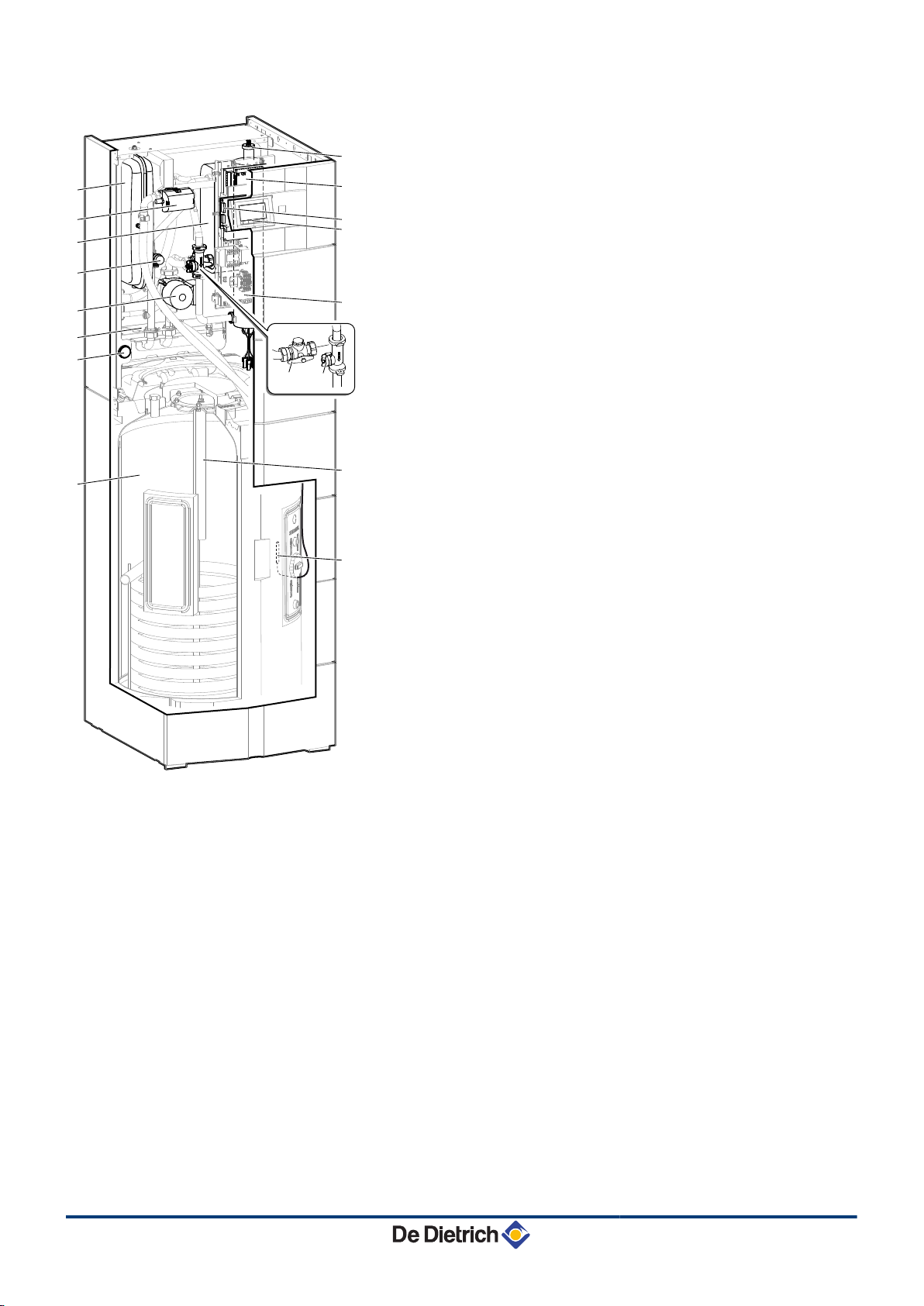
Models: MIV-II/EM-ET V220
1
2
3
4
5
6
7
8
9
10
11
12
13
14
15
16
17
Expansion vessel
3-way valve + Motor
Exchanger
Safety valve
Shunt pump
Connection plate
Pressure gauge
DHW tank
Bleed valve
Interface PCB *1
Control system board
Display
Low-loss header with electrical back-up
500 μm filter with isolating valves
Flowmeter
Magnesium anode
DHW sensor
23/04/2013 - 300026802-001-03
10
Page 12

L000244-C
10
12
11
9
13
16
17
5
4
3
2
1
6
7
8
14
15
3. Description AWHP-V220
3.2.2. Inside module with hydraulic back-up
Model: MIV-II/H V220
1
2
3
4
5
6
7
8
9
10
11
12
13
14
15
16
17
Expansion vessel
3-way valve + Motor
Exchanger
Safety valve
Shunt pump
Connection plate
Pressure gauge
DHW tank
Bleed valve
Interface PCB *1
Control system board
Display
Disconnecting cylinder
500 μm filter with isolating valves
Flowmeter
Magnesium anode
DHW sensor
11
23/04/2013 - 300026802-001-03
Page 13

-
)
m
w
r
r
r
d
d
v
c
d
SERVICE
L000308-A
h
j
A B C D
-
m
r
r
ddd
SERVICE
L000309-A
h
j
w
r
v
c
)
AWHP-V220 3. Description
3.3 Control panel
3.3.1. Description of the keys
A
B
C
D
Escape key G
Heating temperature button d or [-]
DHW temperature button r or [+]
S [Enter] Key
3.3.2. Description of the display
Key functions
n
G
d
[-]
r
[+]
®
Back to the previous level without saving the
modifications made.
Central heating function:
Access to the max. heating temperature parameter.
To reduce a value
DHW function:
Access to the heating set point temperature parameter.
To increase a value
Confirmation of the value displayed
or
Access to the selected menu
23/04/2013 - 300026802-001-03
12
Page 14

)
-
m
r
r
ddd
SERVICE
L000310-A
w
r
v
c
h
j
-
m
r
r
d
d
d
SERVICE
L000311-A
w
r
v
c
h
j
)
-
m
r
r
d
d
d
SERVICE
L000312-A
w
r
v
c
h
j
)
-
m
r
r
ddd
SERVICE
L000313-A
A B C D
w
r
v
c
h
j
)
3. Description
n
AWHP-V220
Menus
W
Q
Operating indicators
n
K
a
v
G
w
r
D
a
User menu
Information menu
Installer menu
A manual vent cycle is running / Permanent display of the
Information menu / The screed drying function is active
In stop/antifreeze mode
Compressor on
Electrical or hydraulic back-up running
cooling mode on
DHW mode running
Central heating off
Default active
Forced back-up operation
n
m
d
r
Manual mode
Additional heating
Additional DHW
3.3.3. Accessing the menus
The various menus can be accessed using various key combinations.
1. Press keys C (r) and D simultaneously.
The symbol W flashes.
13
23/04/2013 - 300026802-001-03
Page 15

)
-
m
r
r
ddd
SERVICE
L000314-A
A B C D
w
r
v
c
h
j
AWHP-V220 3. Description
2. Use the B (-) and C (+) keys to scroll through the menus.
3. To confirm, press the D (S) key.
4 Press the key A (G) to exit the menu.
4 If no keys are pressed for 10 seconds, the screen
goes back to the main display without saving the
parameters.
23/04/2013 - 300026802-001-03
14
Page 16

4. Operating the appliance AWHP-V220
4 Operating the appliance
4.1 Starting the heat pump
WARNING
Only a qualified professional may carry out initial start up
or a start up when the heat pump has completely stopped.
When the appliance is switched on, the control panel indicates its
operating mode:
Screen display
r
r + D
w + r
w
/
To modify the operating mode, see chapter:
¼ "Changing the operating mode", page 17.
4.2 Shutting down the heat pump
Operating mode
4 Heating and domestic hot water
4 Swimming pool and domestic hot water
4 Heating
4 Pool
Domestic hot water
Cooling and domestic hot water
Cooling
Shutdown/Frost Protection
WARNING
It is recommended that the heat pump never be completely
shut down.
Antifreeze protection is no longer guaranteed
automatically if the mains supply is switched off.
4.3 User settings
15
If the central heating and the DHW tank are not used for a long period,
we recommend putting the heat pump in shutdown/frost protection
mode.
¼See chapter: "Changing the operating mode", page 17.
In this mode, the installation’s antifreeze protection remains active.
If no buttons are pressed, the settings menus are exited
automatically after 10 seconds, without saving the
parameters.
23/04/2013 - 300026802-001-03
Page 17

)
-
m
r
r
ddd
SERVICE
L000317-A
A C D
w
r
v
c
h
j
B
)
-
m
r
r
ddd
SERVICE
L000318-A
A B C D
w
r
v
c
h
j
)
-
m
r
r
ddd
SERVICE
L000319-A
A C D
w
r
v
c
h
j
B
)
-
m
r
r
ddd
SERVICE
L000320-A
A B C D
w
r
v
c
h
j
AWHP-V220
4. Operating the appliance
4.3.1.
1. Press the B (d) key.
2. Use the B (-) and C (+) keys to modify the value.
Temperature
Room temperature
setpoint
3.
Press the D (®) key to confirm and exit the menu.
Modifying the set room temperature d
Adjustment range Increment Factory
from 15 to 30°C 1 °C 20 °C
When a room thermostat is connected, set the room
thermostat to a value 2 K higher than the room temperature
setpoint d.
setting
4.3.2. Modifying the domestic hot water
temperaturer
1. Press the C (r) key.
2. Use the B (-) and C (+) keys to modify the value.
Temperature
DHW set temperature from 40 to 65°C 1 °C 50 °C
3.
Press the D (®) key to confirm and exit the menu.
Adjustment range Increment Factory setting
23/04/2013 - 300026802-001-03
16
Page 18

)
-
m
r
r
ddd
SERVICE
L000321-A
A B C D
w
r
v
c
h
j
)
-
m
r
r
ddd
SERVICE
L000322-A
A B C D
w
r
v
c
h
j
)
-
m
r
r
ddd
SERVICE
L000323-A
A C D
w
r
v
c
h
j
B
4. Operating the appliance AWHP-V220
4.3.3. Changing the operating mode
1. Press keys C (r) and (D) simultaneously.
The symbol W flashes.
2. To confirm, press the D (S) key.
3. Use the B (-) and C (+) keys to modify the value.
Operating mode
Heating and domestic hot water 1
Heating 2
Domestic hot water 3
Cooling and domestic hot water 4
Cooling 5
Shutdown/Frost Protection 6
Pool 7
Swimming pool and domestic hot water 8
4.
Press the D (®) key to confirm and exit the menu.
Value Screen display
r
+
r
D
+
w
r
w
/
r
4.3.4. Forcing the additional heating
It is impossible to force the additional heating when the off/
antifreeze mode is selected.
It is possible to force use of the additional heating to complement the
heat pump. To force use of the additional heating, perform the
following operations:
1. Press keys A and D simultaneously.
Hold the keys down.
17
23/04/2013 - 300026802-001-03
Page 19

)
-
m
r
r
ddd
SERVICE
L000324-A
A C D
w
r
v
c
h
j
B
)
-
m
r
r
ddd
SERVICE
L000325-A
A B C D
w
r
v
c
h
j
M003105-A
AWHP-V220
4. Operating the appliance
2. Hold the A key down and press the D key successively to choose
the forcing desired.
Display Back-up
+
m
d
+
m
r
+ d +
m
The m symbol disappears from
the display
r
Forcing additional heating for heating
Forcing additional heating for DHW
Forcing additional heating for heating and
DHW
Additional heating forcing deactivated
4.3.5. Hybrid operating mode
CAUTION
The hybrid operating mode is only available for appliances
with hydraulic back-up.
The appliance offers a choice between several hybrid operating
modes. The modes available offer either optimised energy
consumption according to energy cost, or optimised energy
consumption according to primary energy consumption. Both hybrid
operating modes are available via parameter U1. In optimised
primary energy consumption mode, the control system chooses the
generator that consumes the least primary energy. In optimised
energy cost mode, the control system chooses the cheapest
generator according to the coefficient of performance of the heat
pump and according to energy cost.
To access the parameters:
1. Go to the Installer menu .
See chapter: "Accessing the menus", page 13
¼
2. The symbol flashes.
Press the key D (®) to enter the "Installer" menu.
3. Use the B (-)+ and *2 keys to switch from one parameter to
another.
4. Use the B (-) and *2 keys to change the parameter value.
Press the ® key to confirm the setting.
To modify another parameter, repeat the procedure from
step 3.
5. Press the key A (G) to exit the menu.
23/04/2013 - 300026802-001-03
18
Page 20

)
-
m
r
r
ddd
SERVICE
L000315-A
A B C D
w
r
v
c
h
j
4. Operating the appliance
Choosing the hybrid operating mode
n
Parameter Description Adjustment range Increment Factory setting
Hybrid operating mode
0 to 2
1 0
AWHP-V220
(1)
U1
(1) Only available if p3 = 0
4 0 = Off
4 1 = Optimisation of primary energy consumption
4 2 = Optimisation according to energy cost
It is imperative that you input the energy cost parameters
U2 ,U3, U4 to use the hybrid operating mode
optimised according to energy cost.
Energy cost parameters
n
CAUTION
The currency for parameters U2 ,U3, U4 must be the
same. For example: U2 in euro per kWH and U4 in
euro per litre.
Paramters U2, U3 and U4 are available only if U1
= 2
Parameter Description Adjustment range Increment Factory
setting
U2
U3
U4
(1) Only available if p3 = 0
4 For a standard electricity tariff, input parameter U2.
Tariff per kWh of electricity (Off-peak hours)
4 For a Peak Hours / Off-peak Hours electricity tariff, input
(1)
parameters U2 for the Peak Hours tariff and U3 for the
Off-peak Hours tariff.
Fossil energy tariff for the hydraulic back-up.
(1)
4 Gas boiler: Tariff per m3 of gas. For example: €/m
4 Fuel oil fired boiler: Tariff per litre of oil. For example: €/litre
Tariff per kWh of electricity
(1)
3
0.01 to 2.00
0.01 to 2.00
0.01 to 2.50
0.01 0.13
0.01 0.09
0.01 0.9
4.4 Reading out measured values
19
To display the data in the Information menu, proceed as follows:
1. Go to the Information menu Q.
See chapter: "Accessing the menus", page 13
¼
23/04/2013 - 300026802-001-03
Page 21

)
-
m
r
r
ddd
SERVICE
L000316-A
A B C D
w
r
v
c
h
j
AWHP-V220
4. Operating the appliance
2. Use the B (-) and C (+) keys to scroll through the information.
If no buttons are pressed for 10 seconds, the screen goes
back to the main display.
For permanent information display:
When the word SERVICE flashes, press the A (G) and B
(-) keys simultaneously.
The word SERVICE continues to be displayed and no
longer flashes.
3. Press the key A (G) to exit the menu.
If the information SERVICE is not displayed, the screen will
switch back to the main display after 5 seconds.
The following data can be accessed in the information menu:
Parameter
pB
pC
pD
pE
lp
F.jp
Description Unit
4 In heating mode: Heating flow set point temperature
4 In DHW mode: DHW setpoint temperature
4 In cooling mode: Cooling setpoint temperature
4 In swimming pool mode: Pool set temperature
Measured start temperature °C
Domestic hot water temperature measured °C
Outside temperature measured °C
Water flow l/min
Software version
°C
4.4.1. Energy consumption display
Parameter
gB:
gC:
gD:
(1) Display available if the estimated electrical energy consumption function is activated
(2) Cooling mode must be enabled
Description Unit
Estimated consumption of electrical energy in heating mode
Estimated consumption of electrical energy in DHW mode
Estimated consumption of electrical energy in cooling mode
(2)
(1)
(1)
(1)
kWh
kWh
kWh
23/04/2013 - 300026802-001-03
The estimated electricity consumption is displayed in 3 digits. The
fourth digit indicates the scale (x1, x10, x100, x1000).
20
Page 22

)
-
m
r
r
ddd
SERVICE
C004248-A
A B C D
w
r
v
c
h
j
)
-
m
r
r
ddd
SERVICE
C004249-A
A B C D
w
r
v
c
h
j
)
-
m
r
r
ddd
SERVICE
C004250-A
A B C D
w
r
v
c
h
j
)
-
m
r
r
ddd
SERVICE
C004251-A
A B C D
w
r
v
c
h
j
4. Operating the appliance AWHP-V220
Display example Description
The displayed value is 123 kWh. The unit is 1 kWh.
The displayed value is 1230 kWh. The unit is 10 kWh. The fourth digit indicates
the scale x10. Only the first 3 figures are displayed.
The displayed value is 12300 kWh. The unit is 100 kWh. The fourth digit
indicates the scale x100. Only the first 3 figures are displayed.
The displayed value is 123000 kWh. The unit is 1000 kWh. The fourth digit
indicates the scale x1000. Only the first 3 figures are displayed.
21
23/04/2013 - 300026802-001-03
Page 23

T001507-B
AWHP-V220
5 Checking and maintenance
5.1 General instructions
CAUTION
4 An annual inspection is compulsory.
4 We recommend taking out a maintenance contract.
4 Maintenance operations must be done by a qualified
engineer.
4 Only original spare parts must be used.
4 Make certain that the flues and chimneys are
connected, in good condition and not blocked.
4 Do not modify nor block the condensate outlet(s).
4 If a neutralisation system is installed, follow the
instructions delivered with the neutralisation system
for cleaning and servicing of this system.
5. Checking and maintenance
5.2 Periodic checks
WARNING
Only qualified professionals are permitted access to the
inside of the appliance.
If the pressure gauge is not accessible, contact the
installer.
4 Have the installation’s water pressure checked.
If the water pressure is lower than 1 bar, more water should
be added. If necessary, top up the water level in the heating
system (recommended hydraulic pressure between 1,5
and 2,0 bar).
¼See chapter: "Top up the installation with water",
page 23.
4 Carry out a visual check for the presence of any water leaks.
23/04/2013 - 300026802-001-03
22
Page 24

1
2
3
4
T000181-B
1
2
3
4
T000181-B
1
2
3
4
T000181-B
5. Checking and maintenance
4 Open and close the radiator valves several times a year (this
prevents the valves from seizing up).
4 Clean the outside of the heat pump using a damp cloth and a mild
detergent.
5.3 Top up the installation with water
If necessary, top up the water level in the heating system
(recommended hydraulic pressure between 1.5 and 2 bar).
1. Open the valves on all radiators connected to the heating system.
2. Set the room thermostat to as low a temperature as possible.
3. Put the heat pump in shutdown/frost protection mode.
See chapter: "Changing the operating mode", page 17.
¼
4. Open the filling valve .
5. Close the filling valve when the pressure gauge shows a pressure
of 1,5 bar.
6. Put the heat pump in heating mode.
See chapter: "Changing the operating mode", page 17.
¼
7. When the pump has stopped, bleed again and top up the water
pressure.
AWHP-V220
CAUTION
Only qualified professionals are permitted to clean the
inside of the appliance.
5.4 Bleeding the heating system
It is essential that you bleed any air in the calorifier, the conduits or
the taps to prevent the annoying noises likely to be produced during
heating or when tapping water.
5.4.1. Manual venting
1. Open the valves on all radiators connected to the heating system.
2. Put the heat pump in shutdown/frost protection mode.
Filling and bleeding the installation 2 times a year should
be sufficient to obtain an adequate hydraulic pressure. If it
is often necessary to top up the installation with water,
contact your fitter.
See chapter: "Changing the operating mode", page 17
¼
23
23/04/2013 - 300026802-001-03
Page 25

M001495-A
11
22
)
-
m
r
r
ddd
SERVICE
A000917-A
A C D
w
r
v
c
h
j
B
AWHP-V220 5. Checking and maintenance
3. Vent the underfloor heating circuits and the radiators. First vent
the lower floors A and then the upper floors Z.
5.4.2. Automatic venting
The heat pump runs an automatic venting cycle when it is powered
up. Automatic venting takes approximately one minute.
Automatic venting starts up only if the measured DHW
temperature is lower than 25°C.
It is possible to extend automatic venting manually to run for more
than one minute:
1. The word SERVICE flashes when powering up. Press A and B
(d)-keys simultaneously.
An automatic venting cycle begins. The word SERVICE stops
flashing .
2. Press the A and B (d) keys simultaneously to stop the venting
cycle.
¼Consult the installer for more detailed information.
WARNING
After venting, have the installation’s pressure checked.
Top up with water if necessary.
23/04/2013 - 300026802-001-03
24
Page 26

6. Troubleshooting AWHP-V220
6 Troubleshooting
6.1 Error codes
In the event of problems, the control panel displays the symbol a and
an error code.
WARNING
Make a note of the code displayed.
The error code is important for the correct and rapid
diagnosis of the type of malfunction and for any technical
assistance from your installer.
4 To go back to the main display, press the ® button.
4 The symbol a continues to be displayed as long as the error is
present.
4 Browsing is possible in all menus.
Error
codes
err
e[1
e[2
e[3
e[4
e[5
Description Probable causes Checking / solution
Configuration error
flow sensor failure
Outside temperature sensor
fault
The heat pump continues to
operate at maximum
temperature.
Domestic hot water sensor fault
Flow rate fault
Fault on the outdoor module
4 The control system mode is not
compatible with the configuration of the
installer parameters.
4 Sensor defective
4 Sensor not or badly connected
4 Sensor defective
4 Sensor not or badly connected
4 Sensor defective
4 Sensor not or badly connected.
4 The water level and/or pressure are too
low
4 Too much air
4 Fault on the outdoor module 4 Contact the fitter.
4 Contact the fitter.
4 Contact the fitter.
4 Contact the fitter.
4 Contact the fitter.
4 Check the water pressure in
the installation (Pressure
gauge)
4 Completely vent the indoor
module and the installation for
optimum functioning.
25
23/04/2013 - 300026802-001-03
Page 27

AWHP-V220 6. Troubleshooting
6.2 Incidents and solutions
Problem Probable causes Solution
The radiators are cold.
There is no domestic hot
water.
Significant variations in
domestic hot water
temperature
The heat pump is not
working.
The water pressure is too
low (< 1 bar).
The heating temperature
setting is too low.
The heating mode is
deactivated.
The radiator valves are closed.
The heat pump is not operating.
The water pressure is too low (<
1 bar).
The DHW temperature setting
is too low.
The domestic hot water mode is
deactivated.
The energy-saving shower
head is restricting the water
flow.
The heat pump is not operating.
The water pressure is too low (<
1 bar).
Insufficient water supply
The heating temperature
setting is too low.
The heat pump is not operating.
The water pressure is too low (<
1 bar).
An error code appears on the
display.
Not enough water in the
installation.
Water leak.
4 Increase the value of parameter d or, if a room thermostat
is connected, increase the temperature.
¼See chapter: "Modifying the set room
temperature d", page 16.
4 Activate the heating mode.
¼See chapter: "Changing the operating mode",
page 17.
4 Open the valves on all radiators connected to the heating
system.
4 Check that the heat pump is switched on.
4 Check the fuses and switches on the electrical installation.
4 Top up the installation with water.
¼See chapter: "Top up the installation with
water", page 23.
4 Increase the value of parameter r.
¼See chapter: "Modifying the domestic hot water
temperaturer", page 16.
4 Activate the DHW mode.
¼See chapter: "Changing the operating mode",
page 17.
4 Clean the shower head; replace if necessary.
4 Check that the heat pump is switched on.
4 Check the fuses and switches on the electrical installation.
4 Top up the installation with water.
¼See chapter: "Top up the installation with
water", page 23.
4 Check the water pressure in the installation.
4 Open the valve.
4 Increase the value of parameter d or, if a room thermostat
is connected, increase the temperature.
¼See chapter: "Modifying the set room
temperature d", page 16
4 Check that the boiler is switched on.
4 Check the fuses and switches on the electrical installation.
4 Top up the installation with water.
¼See chapter: "Top up the installation with
water", page 23.
4 Correct the error if possible.
¼See chapter: "Error codes", page 25.
4 Top up the installation with water.
¼See chapter: "Top up the installation with
water", page 23.
4 Contact the fitter.
23/04/2013 - 300026802-001-03
26
Page 28

6. Troubleshooting AWHP-V220
Problem Probable causes Solution
The central heating pipe
connections are too tight.
There is air in the heating pipes.
Clicking in the central heating
pipes
4 Contact the fitter.
4 It is essential that you bleed any air in the calorifier, the
conduits or the taps to prevent the annoying noises likely to
be produced during heating or when tapping water.
¼See chapter: "Bleeding the heating system",
page 23
Significant water leak
underneath or in the vicinity
of the heat pump
The water is circulating too
quickly in the central heating
system.
The pipes on the heat pump or
the central heating are
damaged.
4 Contact the fitter.
4 Contact the fitter.
27
23/04/2013 - 300026802-001-03
Page 29

AWHP-V220 7. Technical specifications
7 Technical specifications
7.1 Technical specifications
7.1.1. Heat pump
Conditions of use:
4 Limit operating temperatures in Hot mode:
- Water: +18 °C / +55 °C
- Outside air: -15 °C / +35 °C
4 Limit operating temperatures in Cooling mode:
- Water: +18 °C / +25 °C
- Outside air: +15 °C / +40 °C
4 Maximum operating pressure: 3 bar
AWHP-V220
Calorific output
Performance coefficient (COP)
Absorbed electrical power
Nominal amperage
Calorific output
Performance coefficient (COP)
Absorbed electrical power
Cooling output
Energy efficiency ratio (EER)
Absorbed electrical power
Sound pressure
Nominal water flow (ΔT = 5K)
Manometric height available at
nominal flow rate
Nominal air flow rate
Power voltage of the outdoor unit V 230 V~ 230 V~ 230 V~ 230 V~ 400 V3~ 230 V~ 400 V3~ 230 V~ 400 V3~
Start-up amperage A 5 5 5 5. 3 5 3 6 3
Sound output - Inside
Sound output - Outside
R410A refrigerant kg 2.1 2.5 3.6 5 5 5 5 5 5
Refrigeration connection (LiquidGas)
(1) Hot mode: Outside air temperature +7 °C, Water temperature at the outlet +35 °C. Performances in line with EN 14511-2.
(2) Hot mode: Outside air temperature +2 °C, Water temperature at the outlet +35 °C. Performances in line with EN 14511-2.
(3) Only in reversible versions
(4) Cooling mode: Outside air temperature +35 °C, Water temperature at the outlet +18 °C. Performances in line with EN 14511-2
(5) 5 m from the appliance, free field.
(6) Noise spread by the envelope - Test conducted in accordance with the standard NF EN 12102
(1)
(1)
(1)
(2)
(2)
(3)
(4)
(5)
(6)
(6)
kW 4.1 5.73 8.08 10.87 10.37 13.07 13.07 14.95 14.95
(1)
kWe 0.95 1.46 2.00 2.57 2.50 3.31 3.31 3.91 3.91
A 4.3 6.8 9.3 11.2 6.7 14.8 8.8 17.7 10.1
kW 4 4.45 5.93 7.57 7.57 10.32 10.32 10.38 10.38
(2)
kWe 1.23 1.43 1.90 2.46 2.46 3.37 3.37 3.36 3.36
kW 3.60 5.40 7.94 10.48 10.48 11.74 11.74 11.70 11.70
(4)(3)
kWe 0.77 1.40 1.99 2.24 2.24 2.65 2.65 2.70 2.70
dB(A) 36 36 36 40 40 41 41 41 41
m3/h
mbar 450 400 200 300 300 120 120 - -
m3/h
dB(A) 43.2 43.2 40.4 38.2 38.2 40.2 40.2 43.4 43.4
dB(A) 63.7 63.7 65.2 65.4 65.4 66.8 66.8 69.4 69.4
inch 1/4-1/2 1/4-1/2 3/8-5/8 3/8-5/8 3/8-5/8 3/8-5/8 3/8-5/8 3/8-5/8 3/8-5/8
4 MR 6 MR 8 MR 11 MR 11 TR 14 MR 14 TR 16 MR 16 TR
4.3 3.93 4.03 4.23 4.15 3.95 3.95 3.82 3.82
3.2 3.12 3.12 3.10 3.10 3.10 3.10 3.10 3.10
4.65 3.80 3.99 4.68 4.68 4.43 4.43 4.40 4.40
0.71 1.04 1.47 1.88 1.88 2.36 2.36 2.67 2.67
2100 2100 3000 6000 6000 6000 6000 6000 6000
23/04/2013 - 300026802-001-03
28
Page 30

7. Technical specifications AWHP-V220
AWHP-V220 4 MR 6 MR 8 MR 11 MR 11 TR 14 MR 14 TR 16 MR 16 TR
Max pre-loaded length m 30 30 30 30 30 30 30 30 30
Weight (empty) - Outside module kg 45 45 75 121 135 116 130 116 130
Weight (empty) - Indoor module kg 35 35 35 37 37 37 37 37 37
(1) Hot mode: Outside air temperature +7 °C, Water temperature at the outlet +35 °C. Performances in line with EN 14511-2.
(2) Hot mode: Outside air temperature +2 °C, Water temperature at the outlet +35 °C. Performances in line with EN 14511-2.
(3) Only in reversible versions
(4) Cooling mode: Outside air temperature +35 °C, Water temperature at the outlet +18 °C. Performances in line with EN 14511-2
(5) 5 m from the appliance, free field.
(6) Noise spread by the envelope - Test conducted in accordance with the standard NF EN 12102
7.1.2. Domestic hot water tanks
Technical specifications
Primary circuit (Heating water) Maximum operating temperature °C 85
Maximum operating pressure bar 3
Exchanger capacity L 14
Exchange surface
2
1.7
m
Secondary circuit (domestic water) Maximum operating temperature °C 70
Maximum operating pressure bar 10
Water content L 220
Weight
Shipping weight kg 112
Domestic hot water tank loading time
AWHP-V220 4 MR 6 MR 8 MR 11 MR - 11 TR 14 MR - 14 TR 16 MR - 16 TR
(1)
Heating time
(1) ΔT = 40 K. Outside air temperature: 7 °C. Inside air temperature: 20 °C
2 h 39 min 1 h 42 min 1 h 25 min 1 h 19 min 1 h 16 min 1 h 14 min
29
23/04/2013 - 300026802-001-03
Page 31

AWHP-V220
8 Energy savings
8.1 Energy savings
8. Energy savings
This chapter contains:
4 Energy-saving advice
4 Advice on setting the room thermostat correctly
8.1.1. Energy-saving advice
4 Do not block ventilation outlets.
4 Install reflective panels behind the radiators to prevent heat
losses.
4 Do not cover the radiators. Do not hang curtains in front of the
radiators.
4 Insulate the pipes in rooms that are not heated (cellars and lofts).
4 Close the radiators in rooms not in use.
4 Do not run hot (or cold) water pointlessly.
4 Install a water-saving shower head to save up to 40 % energy.
4 Take showers rather than baths. A bath consumes twice as much
water and energy.
8.1.2. Room thermostat and settings
4 A modulating thermostat, possibly in combination with
thermostatic valve radiators, saves energy and offers
considerable comfort. This combination allows you to set the
temperature on each flow. In the room in which the room
thermostat is installed, do not fit thermostatic valve radiators.
4 Lower the thermostat to approximately 16°C at night or when you
are absent. This reduces heating costs and energy consumption.
4 Lower the room thermostat when you air the rooms.
4 When setting an hourly programmable thermostat, keep in mind
the days you are absent or on vacation.
23/04/2013 - 300026802-001-03
30
Page 32

9. Warranty
9 Warranty
9.1 General
9.2 Warranty terms
AWHP-V220
You have just purchased one of our appliances and we thank you for
the trust you have placed in our products.
Please note that your appliance will provide good service for a longer
period of time if it is regularly checked and maintained.
Your fitter and our customer support network are at your disposal at
all times.
The following provisions are not exclusive of the buyer being able
benefit from the legal provisions applicable regarding hidden defects
in the buyer’s country.
Starting from the purchase date shown on the original fitter’s invoice,
your appliance has a contractual guarantee against any
manufacturing defect.
The length of the guarantee is mentioned in the price catalogue.
The manufacturer is not liable for any improper use of the appliance
or failure to maintain or install the unit correctly (the user shall take
care to ensure that the system is installed by a qualified engineer).
In particular, the manufacturer shall not be held responsible for any
damage, loss or injury caused by installations which do not comply
with the following:
4 applicable local laws and regulations,
4 specific requirements relating to the installation, such as national
and/or local regulations,
4 the manufacturer’s instructions, in particular those relating to the
regular maintenance of the unit,
4 the rules of the profession.
The warranty is limited to the exchange or repair of such parts as have
been recognised to be faulty by our technical department and does
not cover labour, travel and carriage costs.
The warranty shall not apply to the replacement or repair of parts
damaged by normal wear and tear, negligence, repairs by unqualified
parties, faulty or insufficient monitoring and maintenance, faulty
power supply or the use of unsuitable fuel.
31
Sub-assemblies such as motors, pumps, electric valves etc. are
guaranteed only if they have never been dismantled.
The legislation laid down by european directive 99/44/EEC,
transposed by legislative decree No. 24 of 2 February 2002 published
in O.J. No. 57 of 8 March 2002, continues to apply.
23/04/2013 - 300026802-001-03
Page 33

AWHP-V220 9. Warranty
23/04/2013 - 300026802-001-03
32
Page 34

Page 35

Page 36

AD001NU-Ai
DUEDI S.r.l.
DE DIETRICH SERVICE
BDR Thermea (Czech republic) s.r.o
www.duediclima.it
www.dedietrich.cz
Distributore Ufficiale Esclusivo
De Dietrich-Thermique Italia
www.dedietrich-heiztechnik.com
Freecall 0800 / 201608
Jeseniova 2770/56
130 00 Praha 3
+49 (0)25 72 / 9161-0
+49 (0)25 72 / 9161-102
info@remeha.de
Via Passatore, 12 - 12010
San Defendente di Cervasca
CUNEO
+39 0171 857170
+39 0171 687875
info@duediclima.it
+420 271 001 627
info@dedietrich.cz
IT
DE DIETRICH THERMIQUE Iberia S.L.U.
www.dedietrich-calefaccion.es
Av. Princep d’Astúries 43-45
08012 BARCELONA
+34 932 920 520
+34 932 184 709
ES
129164, Россия, г. Москва
Зубарев переулок, д. 15/1
Бизнес-центр «Чайка Плаза»,
офис 309
+7 (495) 221-31-51
CZ
DE DIETRICH THERMIQUE S.A.S
M001476-C
R410AR410A
300026802- 001-03
DEDIETRICH THERMIQUE
57,ruedelaGareF-67580MERTZWILLER-BP 30
© Copyright
All technical and technological information contained in these technical instructions,
as well as any drawings and technical descriptions supplied, remain our property
and shall not be multiplied without our prior consent in writing.
23/04/2013
 Loading...