

Page 1
Regulation
C003674-B
VM iSystem
EN
User Guide
300028026-001-A
Page 2

Contents
1 Introduction ................................................................................................4
1.1 Symbols used .......................................................4
1.2 Abbreviations ........................................................4
1.3 General ..................................................................4
1.3.1 Manufacturer's liability .............................................4
1.3.2 Installer's liability .....................................................5
1.3.3 User's liability ..........................................................5
1.4 Certifications .........................................................6
2 Description ..................................................................................................7
2.1 Description of the keys ........................................7
2.2 Description of the display ....................................8
2.2.1 Key functions ...........................................................8
2.2.2 Flame symbol ..........................................................8
2.2.3 Solar (If connected) .................................................8
2.2.4 Operating modes .....................................................9
2.2.5 Domestic Hot Water override ..................................9
2.2.6 Other information ..................................................10
3 Operating the appliance ..........................................................................11
3.1 Browsing in the menus ......................................11
3.2 Reading out measured values ...........................12
3.3 Changing the settings ........................................13
3.3.1 Setting the set point temperatures ........................13
3.3.2 Selecting the operating mode ...............................14
3.3.3 Forcing domestic hot water production .................15
3.3.4 Setting the contrast and lighting on the
display ...................................................................15
3.3.5 Setting the time and date ......................................16
3.3.6 Selecting a timer programme ................................16
3.3.7 Customising a timer programme ...........................17
3.3.8 Setting an annual clock .........................................19
1
17/11/2011 - 300028026-001-A
Page 3

Contents
3.4 Installation shutdown .........................................21
3.5 Frost protection ..................................................21
4 Troubleshooting .......................................................................................22
4.1 Messages (type code Mxx) ................................22
4.2 Faults ...................................................................22
5 Warranty ....................................................................................................25
5.1 General ................................................................25
5.2 Warranty terms ...................................................25
2
17/11/2011 - 300028026-001-A
Page 4

3
17/11/2011 - 300028026-001-A
Page 5
VM iSystem
1 Introduction
1.1 Symbols used
1. Introduction
In these instructions, various danger levels are employed to draw the
user's attention to particular information. In so doing, we wish to
safeguard the user's safety, obviate hazards and guarantee correct
operation of the appliance.
DANGER
Risk of a dangerous situation causing serious physical
injury.
WARNING
Risk of a dangerous situation causing slight physical
injury.
1.2 Abbreviations
1.3 General
CAUTION
Risk of material damage.
Signals important information.
¼ Signals a referral to other instructions or other pages in the
instructions.
4 DHW: Domestic hot water
4 3WV: 3-way valve
1.3.1. Manufacturer's liability
17/11/2011 - 300028026-001-A
Our products are manufactured in compliance with the requirements
of the various applicable European Directives. They are therefore
delivered with [ marking and all relevant documentation.
4
Page 6

1. Introduction
VM iSystem
In the interest of customers, we are continuously endeavouring to
make improvements in product quality. All the specifications stated in
this document are therefore subject to change without notice.
Our liability as the manufacturer may not be invoked in the following
cases:
4 Failure to abide by the instructions on using the appliance.
4 Faulty or insufficient maintenance of the appliance.
4 Failure to abide by the instructions on installing the appliance.
1.3.2. Installer's liability
The installer is responsible for the installation and inital start up of the
appliance. The installer must respect the following instructions:
4 Read and follow the instructions given in the manuals provided
with the appliance.
4 Carry out installation in compliance with the prevailing legislation
and standards.
4 Perform the initial start up and carry out any checks necessary.
4 Explain the installation to the user.
4 If a maintenance is necessary, warn the user of the obligation to
check the appliance and maintain it in good working order.
4 Give all the instruction manuals to the user.
1.3.3. User's liability
To guarantee optimum operation of the appliance, the user must
respect the following instructions:
4 Read and follow the instructions given in the manuals provided
with the appliance.
4 Call on qualified professionals to carry out installation and initial
start up.
4 Get your fitter to explain your installation to you.
4 Have the required checks and services done.
4 Keep the instruction manuals in good condition close to the
appliance.
This appliance is not intended to be used by persons (including
children) whose physcial, sensory or mental capacity is impaired or
persons with no experience or knowledge, unless they have the
benefit, through the intermediary of a person responsible for their
safety, of supervision or prior instructions regarding use of the
appliance. Care should be taken to ensure that children do not play
with the appliance.
5
17/11/2011 - 300028026-001-A
Page 7

VM iSystem 1. Introduction
1.4 Certifications
This product complies to the requirements to the european directives
and following standards:
4 2006/95/EC Low Voltage Directive. Reference Standard:
EN60.335.1.
4 2004/108/EC Electromagnetic Compatibility Directive. Generic
standards: EN1000-6-3 , EN 61000-6-1.
17/11/2011 - 300028026-001-A
6
Page 8
C003672-B
bar
STD
0 2 4 6 8 10 12 14 16 18 22 2420
AUTO
A
B
C
D
E
F
J
H
G
2. Description VM iSystem
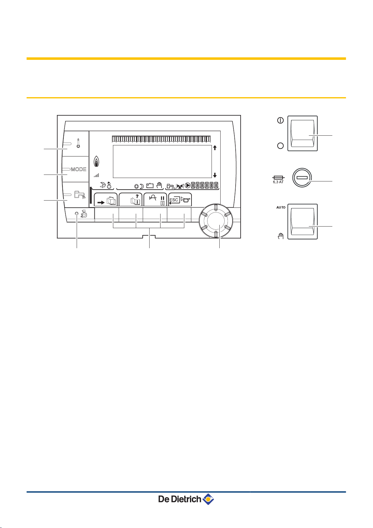
2 Description
2.1 Description of the keys
A
B
C
D
E
F
G
H
J
Temperature setting key (heating, DHW, swimming pool)
Operating mode selection key
DHW override key
Key to access the parameters reserved for the installer
Keys on which the function varies as and when selections
are made
Rotary setting button:
4 Turn the rotary button to scroll through the menus or
modify a value
4 Press the rotary button to access the menu selected
or confirm a value modification
Button AUTO/MANU
Fuse
Button ON/OFF
7
17/11/2011 - 300028026-001-A
Page 9
L000200-A
L000201-A
L000198-A
L000199-A
bar
r
STD
(
'
t
0 2 4 6 8 10 12 14 16 18 22 2420
C002696-A
p
b
AUTO
x
c
r
j
L
g
m
bar
STD
t
0 2 4 6 8 10 12 14 16 18 22 2420
C002701-B
p
b
AUTO
x
c
r
j
M
g
m
bar
STD
t
0 2 4 6 8 10 12 14 16 18 22 2420
L000197-A
p
b
AUTO
x
c
r
j
M
g
m
VM iSystem 2. Description
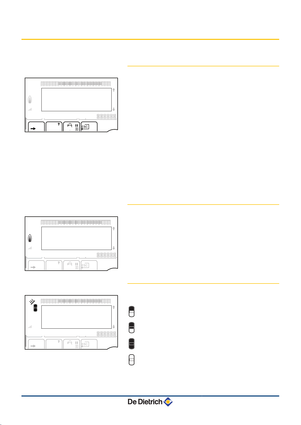
2.2 Description of the display
2.2.1. Key functions
>
(
'
?
f
STD
b
Access to the various menus
Used to scroll through the menus
Used to scroll through the parameters
The symbol is displayed when help is available
Used to display the curve of the parameter selected
Reset of the time programmes
Selection of comfort mode or selection of the days to be
programmed
v
Selection of reduced mode or deselection of the days to
be programmed
j
ESC
Back to the previous level
Back to the previous level without saving the
modifications made
2.2.2. Flame symbol
4 The symbol is displayed: The burner is operating.
4 The symbol is not displayed: The burner is off.
17/11/2011 - 300028026-001-A
2.2.3. Solar (If connected)
u
The solar load pump is running
The top part of the tank is reheated to the tank set point
The entire tank is reheated to the tank set point
The entire tank is reheated to the solar tank set point
The tank is not loaded - Presence of the solar control
system
8
Page 10

bar
STD
t
0 2 4 6 8 10 12 14 16 18 22 2420
C002697-B
p
b
AUTO
x
c
r
j
M
g
m
bar
STD
t
0 2 4 6 8 10 12 14 16 18 22 2420
C002698-B
p
b
AUTO
x
c
r
j
M
g
m
bar
STD
t
0 2 4 6 8 10 12 14 16 18 22 2420
C002707-A
p
b
AUTO
x
c
r
j
M
g
m
2. Description VM iSystem
2.2.4. Operating modes
p
b
AUTO
x
m
g
Summer mode: The heating is off. Domestic hot water
continues to be produced
WINTER mode: Heating and domestic hot water working
Operation in automatic mode according to the timer
programme
Comfort mode: The symbol is displayed when a DAY
override (comfort) is activated
4 Flashing symbol: Temporary override
4 Steady symbol: Permanent override
Reduced mode: The symbol is displayed when a NIGHT
override (reduced) is activated
4 Flashing symbol: Temporary override
4 Steady symbol: Permanent override
Holiday mode: The symbol is displayed when a HOLIDAY
override (antifreeze) is activated
4 Flashing symbol: Holiday mode programmed
4 Steady symbol: Holiday mode active
m
Manual mode
2.2.5. Domestic Hot Water override
A bar is displayed when a DHW override is activated:
4 Flashing bar: Temporary override
4 Steady bar: Permanent override
9
17/11/2011 - 300028026-001-A
Page 11

bar
STD
t
0 2 4 6 8 10 12 14 16 18 22 2420
C002699-B
p
b
AUTO
x
c
r
j
M
g
m
VM iSystem 2. Description
2.2.6. Other information
r
w
M
The symbol is displayed when domestic hot water
production is running.
Valve indicator: The symbol is displayed when a 3-way
valve is connected.
4 x : 3-way valve opens
4 c : 3-way valve closes
The symbol is displayed when the pump is operating.
Name of the circuit for which the parameters are
displayed.
17/11/2011 - 300028026-001-A
10
Page 12

bar
1
1
2
2
r
c
STD
(
'
t
v
0 2 4 6 8 10 12 14 16 18 22 2420
p
b
AUTO
x
c
r
j
L
g
m
#MEASURES
#CHOICE TIME PROG.
#TIME PROGRAM
#SETTING
#TIME .DAY
a
C002220-B-04
bar
1
1
2
2
r
c
STD
(
'
t
v
0 2 4 6 8 10 12 14 16 18 22 2420
p
b
AUTO
x
c
r
j
L
g
m
CURRENT PROG.B
CURRENT PROG.C
P2
P3
a
C002221-C-04
bar
1
1
2
2
r
c
STD
(
'
t
v
0 2 4 6 8 10 12 14 16 18 22 2420
p
b
AUTO
x
c
r
j
L
g
m
CURRENT PROG.C
"Choice of the timeprogram
applied C"
P4
a
C002222-C-04
bar
1
1
2
2
r
c
STD
(
'
t
v
0 2 4 6 8 10 12 14 16 18 22 2420
p
b
AUTO
x
c
r
j
M
g
m
LUNDI 11:45
C002224-D-04
2x
3. Operating the appliance VM iSystem
3 Operating the appliance
3.1 Browsing in the menus
1. To select the desired menu, turn the rotary button.
2. To access the menu, press the rotary button.
To go back to the previous display, press the key j.
3. To select the desired parameter, turn the rotary button.
4. To modify the parameter, press the rotary button.
To go back to the previous display, press the key j.
5. To modify the parameter, turn the rotary button.
6. To confirm, press the rotary button.
To cancel, press key
h
.
7. To go back to the main display, press key j2 times.
It is possible to use the ( and ' keys instead of the rotary
button.
11
17/11/2011 - 300028026-001-A
Page 13

bar
1
1
2
2
r
c
STD
(
'
t
v
0 2 4 6 8 10 12 14 16 18 22 2420
p
b
AUTO
x
c
r
j
M
g
m
SUNDAY 11:45
C002219-D-04
VM iSystem 3. Operating the appliance
3.2 Reading out measured values
The various values measured by the appliance are displayed in the
#MEASURES menu.
1. To access user level: Press the > key.
2. Select the menu #MEASURES.
4 Turn the rotary button to scroll through the menus or
modify a value.
4 Press the rotary button to access the menu selected
or confirm a value modification.
For a detailed explanation of menu browsing, refer
¼
to the chapter: "Browsing in the menus", page 11.
User level - #MEASURES menu
Parameter Description Unit
OUTSIDE TEMP.
ROOMTEMP. B
ROOMTEMP. C
BOILER TEMP.
WATER TEMP.
STOR.TANK.TEMP
(1)
SWIMMING P.T.B
(1)
SWIMMING P.T.C
(1)
OUTLET TEMP. B
(1)
OUTLET TEMP. C
(1)
SYSTEM TEMP.
T.DHW BOTTOM
(1)
TEMP.TANK AUX
(1)
TEMP.SOL.TANK
(1)(2)
SOLAR.COLL.T.
(2)
SOLA.ENERGY
(2)
IN 0-10V
(1)(2)
CTRL Software control number
(1) The parameter is only displayed for the options, circuits or sensors actually connected.
(2) According to the configuration
17/11/2011 - 300028026-001-A
Outside temperature °C
(1)
Room temperature of circuit B °C
(1)
Room temperature of circuit C °C
(2)
Water temperature in the boiler °C
(1)
Water temperature in the DHW tank °C
Water temperature in the storage tank °C
Water temperature of the swimming pool on circuit B °C
Water temperature of the swimming pool on circuit C °C
Temperature of the flow water in circuit B °C
Temperature of the flow water in circuit C °C
(1)
Temperature of the system flow water if multi-generator °C
Water temperature in the bottom of the DHW tank °C
Water temperature in the second DHW tank connected to the AUX circuit °C
Temperature of the hot water produced by solar power (TS) °C
(1)
Solar panel temperature (TC) °C
(1)
Solar energy accumulated in the tank kWh
Voltage at input 0-10 V V
12
Page 14
MODE
C002266-A
3. Operating the appliance VM iSystem
3.3 Changing the settings
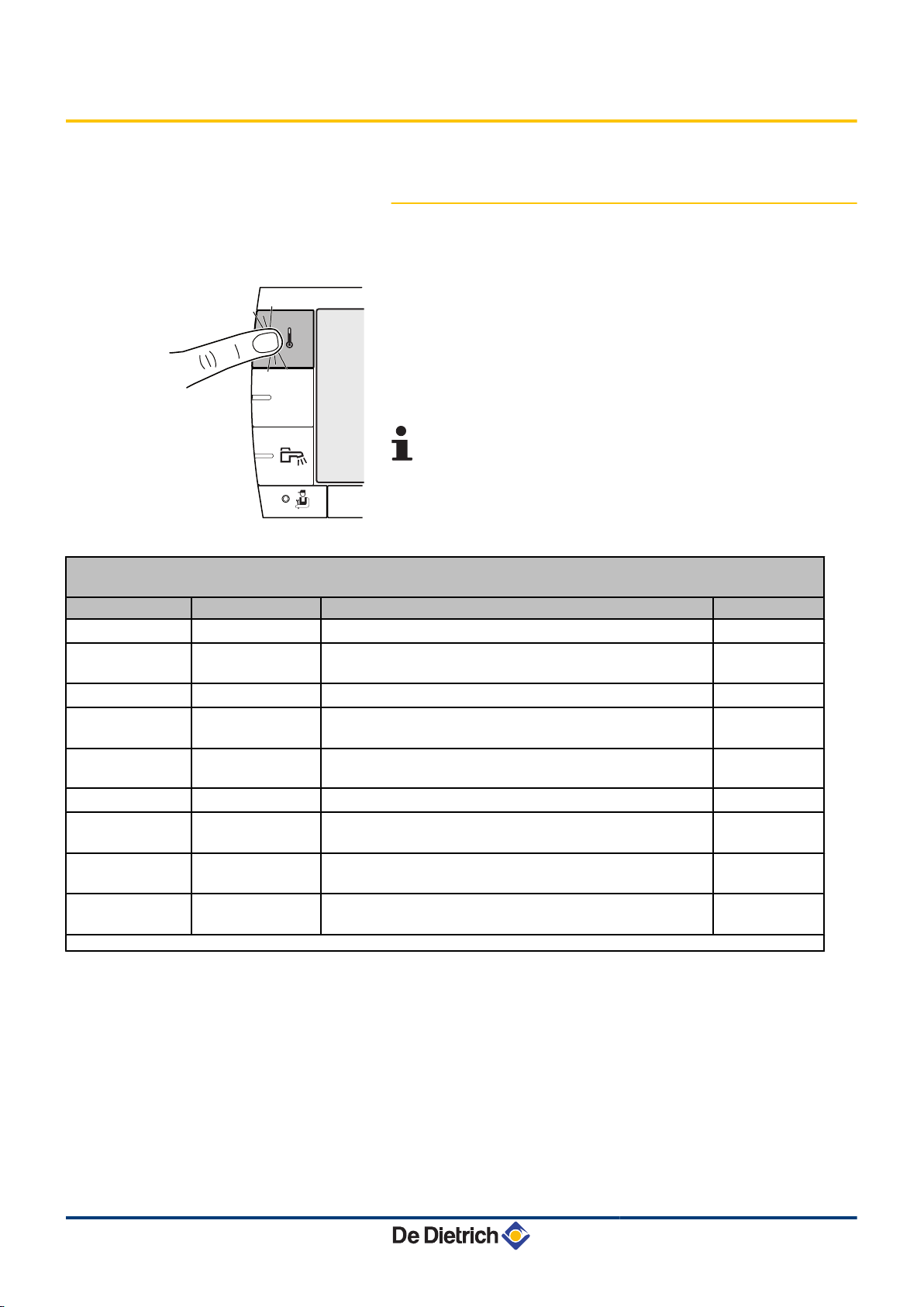
3.3.1. Setting the set point temperatures
To set the various heating, DHW and swimming pool temperatures,
proceed as follows:
1. Press the C key.
2. To select the desired parameter, turn the rotary button.
3. To modify the parameter, press the rotary button.
To go back to the previous display, press the key j.
4. To modify the parameter, turn the rotary button.
5. To confirm, press the rotary button.
To cancel, press key
h
.
Menu C
Parameter Adjustment range Description Factory setting
(1)
DAY TEMP. B
NIGHT TEMP. B
(1)
DAY TEMP. C
NIGHT TEMP. C
(1)
TEMP.SOL.TANK
(1)
WATER TEMP.
TEMP.TANK AUX
(1)
SWIMMING P.T.B
(1)
SWIMMING P.T.C
(1)
(1) The parameter is only displayed for the options, circuits or sensors actually connected.
5 to 30 °C Desired room temperature in comfort periods on circuit B 20 °C
5 to 30 °C Desired room temperature in reduced periods on circuit B 16 °C
(1)
5 to 30 °C Desired room temperature in comfort periods on circuit C 20 °C
5 to 30 °C Desired room temperature in reduced periods on circuit B 16 °C
20 to 80 °C Maximum load temperature of the tank's solar zone 60°C
(1)
10 to 80 °C Desired domestic hot water temperature in the DHW circuit 55 °C
10 to 80 °C Desired domestic hot water temperature in the auxiliary circuit 55 °C
5 to 39 °C Desired temperature for swimming pool B 20 °C
5 to 39 °C Desired temperature for swimming pool C 20 °C
13
17/11/2011 - 300028026-001-A
Page 15

MODE
C002267-A
VM iSystem 3. Operating the appliance
3.3.2. Selecting the operating mode
To select an operating mode, proceed as follows:
1. Press the MODE key.
2. To select the desired parameter, turn the rotary button.
3. To modify the parameter, press the rotary button.
To go back to the previous display, press the key j.
4. To modify the parameter, turn the rotary button.
5. To confirm, press the rotary button.
To cancel, press key h.
Menu MODE
Parameter Adjustment range Description Factory setting
AUTOMATIQUE
DAY
NIGHT
HOLIDAYS
SUMMER
MANUEL
FORCE AUTO
(1) The start and end days and the number of days are calculated in relation to each other.
(2) According to the configuration
(2)
7/7, xx:xx Comfort mode is forced until the time indicated or all the time (7/7). Present time + 1
7/7, xx:xx Reduced mode is forced until the time indicated or all the time (7/7). Present time + 1
7/7, 1 to 365 The antifreeze mode is active on all boiler circuits.
YES / NO An operating mode override is activated on the remote control
The comfort ranges are determined by the timer programme.
Number of days' holiday: xx
heating OFF: xx:xx
Restarting: xx:xx
The heating is off.
Domestic hot water continues to be produced.
The generator operates according to the set point setting. All of the
pumps operate. Option of setting the set point by simply turning the
rotary button.
(option).
To force all circuits to run on AUTOMATIQUE mode, select YES.
(1)
(1)
(1)
hour
hour
Present date + 1
day
17/11/2011 - 300028026-001-A
14
Page 16

MODE
C002268-A
bar
1
1
2
2
r
c
STD
(
'
t
v
0 2 4 6 8 10 12 14 16 18 22 2420
p
b
AUTO
x
c
r
j
M
g
m
SUNDAY 11:45
C002219-D-04
3. Operating the appliance VM iSystem
3.3.3. Forcing domestic hot water production
To force domestic hot water production, proceed as follows:
1. Press the r key.
2. To select the desired parameter, turn the rotary button.
3. To modify the parameter, press the rotary button.
To go back to the previous display, press the key j.
4. To modify the parameter, turn the rotary button.
5. To confirm, press the rotary button.
To cancel, press key h.
Menu r
Parameter Description Factory setting
AUTOMATIQUE
COMFORT
The domestic hot water comfort ranges are determined by the timer programme.
Domestic hot water comfort mode is forced until the time indicated or all the time (7/7). Present time + 1 hour
3.3.4. Setting the contrast and lighting on the
display
1. To access user level: Press the > key.
2. Select the menu #SETTING.
4
Turn the rotary button to scroll through the menus or
modify a value.
4 Press the rotary button to access the menu selected
or confirm a value modification.
For a detailed explanation of menu browsing, refer
¼
to the chapter: "Browsing in the menus", page 11.
3. To set the following parameters:
User level - Menu #SETTING
Parameter Adjustment range Description Factory setting Customer setting
CONTRAST DISP.
BACK LIGHT COMFORT
ECO
Adjusting the display contrast.
The screen is illuminated continuously in
daytime periods.
The screen is illuminated for 2 minutes
whenever pressed.
ECO
15
17/11/2011 - 300028026-001-A
Page 17

bar
1
1
2
2
r
c
STD
(
'
t
v
0 2 4 6 8 10 12 14 16 18 22 2420
p
b
AUTO
x
c
r
j
M
g
m
SUNDAY 11:45
C002219-D-04
bar
1
1
2
2
r
c
STD
(
'
t
v
0 2 4 6 8 10 12 14 16 18 22 2420
p
b
AUTO
x
c
r
j
M
g
m
SUNDAY 11:45
C002219-D-04
VM iSystem
3.3.5. Setting the time and date
1. To access user level: Press the > key.
2. Select the menu #TIME .DAY.
4 Turn the rotary button to scroll through the menus or
modify a value.
4 Press the rotary button to access the menu selected
or confirm a value modification.
For a detailed explanation of menu browsing, refer
¼
to the chapter: "Browsing in the menus", page 11.
3. To set the following parameters:
3. Operating the appliance
User level - Menu #TIME .DAY
(1)
Parameter Adjustment range Description Factory setting Customer setting
HOURS
MINUTE
DAY
DATE
MONTH
YEAR
SUM. TIME: AUTO
0 to 23 Hours setting
0 to 59 Minutes setting
Monday to Sunday Setting the day of the week
1 to 31 Day setting
January to December Month setting
2008 to 2099 Year setting
automatic switch to summer time on the last Sunday
AUTO
in March and back to winter time on the last Sunday
in October.
MANU
for countries where the time change is done on
other dates or is not in use.
(1) According to the configuration
3.3.6. Selecting a timer programme
1. To access user level: Press the > key.
2. Select the menu #CHOICE TIME PROG..
17/11/2011 - 300028026-001-A
4
Turn the rotary button to scroll through the menus or
modify a value.
4 Press the rotary button to access the menu selected
or confirm a value modification.
For a detailed explanation of menu browsing, refer
¼
to the chapter: "Browsing in the menus", page 11.
3. To select the desired parameter.
User level - Menu
Parameter Adjustment range Description
CURRENT PROG.B
CURRENT PROG.C
#CHOICE TIME PROG.
P1 / P2 / P3 / P4 Comfort programme activated
(Circuit B)
P1 / P2 / P3 / P4 Comfort programme activated
(Circuit C)
4. Assign the desired timer programme (P1 to P4) to the circuit with
the rotary button.
16
Page 18

bar
1
1
2
2
r
c
STD
(
'
t
v
0 2 4 6 8 10 12 14 16 18 22 2420
p
b
AUTO
x
c
r
j
M
g
m
SUNDAY 11:45
C002219-D-04
bar
1
1
2
2
r
c
STD
(
'
t
v
0 2 4 6 8 10 12 14 16 18 22 2420
p
b
AUTO
x
c
r
j
L
g
m
PROG P2 C
Mo Tu We Th Fr Sa Su
"Display of the timeprogram.
To continuepush on the button"
a
C002228-B-04
bar
1
1
2
2
r
c
STD
(
'
t
v
0 2 4 6 8 10 12 14 16 18 22 2420
p
b
AUTO
x
c
r
j
L
g
m
PROG P2 C
Mo Tu
We Th Fr Sa Su
"Select the days to
program"
a
C002229-C-04
3. Operating the appliance
3.3.7. Customising a timer programme
1. To access user level: Press the > key.
2. Select the menu #TIME PROGRAM.
4 Turn the rotary button to scroll through the menus or
modify a value.
4 Press the rotary button to access the menu selected
or confirm a value modification.
For a detailed explanation of menu browsing, refer
¼
to the chapter: "Browsing in the menus", page 11.
3. To select the desired parameter.
User level - Menu #TIME PROGRAM
Parameter Time schedule Description
TIME PROG.B PROG P2 B
PROG P3 B
PROG P4 B
TIME PROG.C PROG P2 C
PROG P3 C
PROG P4 C
TIME PROG.DHW
TIME PROG.AUX
Timer programme for circuit B
Timer programme for circuit C
DHW circuit timer programme
Auxiliary circuit timer programme
VM iSystem
4. To select a timer programme to be modified.
To select to days for which the timer programme is to be
5.
modified:
Turn the rotary button to the left until you reach the day desired.
To confirm, press the rotary button.
6.b : Day selection
Press key b / v until the symbol b is displayed.
Turn the rotary button to the right to select the day(s) desired.
: Cancelling the day selection
v
Press key b / v until the symbol v is displayed.
Turn the rotary button to the right to cancel selection of the relevant
day(s).
7. When the days desired for the programme have been selected,
press the rotary button to confirm.
17
17/11/2011 - 300028026-001-A
Page 19

bar
1
1
2
2
r
c
STD
(
'
t
v
0 2 4 6 8 10 12 14 16 18 22 2420
p
b
AUTO
x
c
r
j
L
g
m
PROG P2 C
Mo Tu
We Th Fr Sa Su
Set the time program.
a
C002230-E-04
06:00
06:00
VM iSystem 3. Operating the appliance
To define the timer ranges for the comfort mode and reduced
8.
mode:
Turn the rotary button to the left until 0:00 is displayed. The first
segment of the graphic bar for the timer programme flashes.
9.b : Comfort mode selection
Press key b / v until the symbol b is displayed.
To select a comfort time range, turn the rotary button to the right.
: Reduced mode selection
v
Press key b / v until the symbol v is displayed.
To select a reduced time range, turn the rotary button to the right.
10.When the times for the comfort mode have been selected, press
the rotary button to confirm.
User level - Menu #TIME PROGRAM
TIME PROG.B
TIME PROG.C
TIME PROG.DHW
TIME PROG.AUX
Day Comfort periods / Filling enabled:
P1
P2 _______________ P3 _______________ P4 _______________
_______________
Monday 6:00 to 22:00
Tuesday 6:00 to 22:00
Wednesday 6:00 to 22:00
Thursday 6:00 to 22:00
Friday 6:00 to 22:00
Saturday 6:00 to 22:00
Sunday 6:00 to 22:00
Monday 6:00 to 22:00
Tuesday 6:00 to 22:00
Wednesday 6:00 to 22:00
Thursday 6:00 to 22:00
Friday 6:00 to 22:00
Saturday 6:00 to 22:00
Sunday 6:00 to 22:00
Monday
Tuesday
Wednesday
Thursday
Friday
Saturday
Sunday
Monday
Tuesday
Wednesday
Thursday
Friday
Saturday
Sunday
17/11/2011 - 300028026-001-A
18
Page 20

bar
1
1
2
2
r
c
STD
(
'
t
v
0 2 4 6 8 10 12 14 16 18 22 2420
p
b
AUTO
x
c
r
j
M
g
m
SUNDAY 11:45
C002219-D-04
3. Operating the appliance
VM iSystem
3.3.8. Setting an annual clock
The annual clock is used to programme up to 10 heating stop periods
over one year. The circuits selected for this stop are in Antifreeze
mode during the period chosen.
1. To access user level: Press the > key.
2. Select the menu #ANNUAL PROG.
4 Turn the rotary button to scroll through the menus or
modify a value.
4 Press the rotary button to access the menu selected
or confirm a value modification.
For a detailed explanation of menu browsing, refer
¼
to the chapter: "Browsing in the menus", page 11.
3. To select the desired parameter.
OFF
No stop
B
circuit B
C
circuit C
B+C
circuit B, C
SU
DHW circuit
B+E
circuit B and DHW
C+E
circuit C and DHW
ALL
circuit B, C and DHW
4. Set the start date and the end date of the shutdown selected.
5. To deactivate a shutdown, select the shutdown and set to OFF.
6. To select another shutdown, press the ' button.
Annual programme (Factory setting)
Stop no. Circuit concerned Start date End date
1
2
3
4
5
6
7
8
9
10
For example: Customised programming
Stop no. Circuit concerned Start date End date
1
2
OFF
OFF
OFF
OFF
OFF
OFF
OFF
OFF
OFF
OFF
AC
AC
01-01 01-01
01-01 01-01
01-01 01-01
01-01 01-01
01-01 01-01
01-01 01-01
01-01 01-01
01-01 01-01
01-01 01-01
01-01 01-01
01-11 10-11
20-12 02-01
19
If setting STOP: OFF, the stop is deactivated and the start and end
dates are not displayed.
17/11/2011 - 300028026-001-A
Page 21

VM iSystem 3. Operating the appliance
User level - Menu #ANNUAL PROG
STOP N 1:
STOP N 2:
STOP N 3:
STOP N 4:
STOP N 5:
STOP N 6:
STOP N 7:
STOP N 8:
STOP N 9:
STOP N 10:
BEG.DATE N 01
BEG.MONTH N 01
END DATE N 01
END MONTH N 01
BEG.DATE N 02
BEG.MONTH N 02
END DATE N 02
END MONTH N 02
BEG.DATE N 03
BEG.MONTH N 03
END DATE N 03
END MONTH N 03
BEG.DATE N 04
BEG.MONTH N 04
END DATE N 04
END MONTH N 04
BEG.DATE N 05
BEG.MONTH N 05
END DATE N 05
END MONTH N 05
BEG.DATE N 06
BEG.MONTH N 06
END DATE N 06
END MONTH N 06
BEG.DATE N 07
BEG.MONTH N 07
END DATE N 07
END MONTH N 07
BEG.DATE N 08
BEG.MONTH N 08
END DATE N 08
END MONTH N 08
BEG.DATE N 09
BEG.MONTH N 09
END DATE N 09
END MONTH N 09
BEG.DATE N 10
BEG.MONTH N 10
END DATE N 10
END MONTH N 10
Description Factory setting Adjustment range
Selection of the circuit stopped
Setting start date of the stop 01 1-31
Setting start month of the stop 01 1-12
Setting end date of the stop 01 1-31
Setting end month of the stop 01 1-12
Selection of the circuit stopped
Setting start date of the stop 01 1-31
Setting start month of the stop 01 1-12
Setting end date of the stop 01 1-31
Setting end month of the stop 01 1-12
Selection of the circuit stopped
Setting start date of the stop 01 1-31
Setting start month of the stop 01 1-12
Setting end date of the stop 01 1-31
Setting end month of the stop 01 1-12
Selection of the circuit stopped
Setting start date of the stop 01 1-31
Setting start month of the stop 01 1-12
Setting end date of the stop 01 1-31
Setting end month of the stop 01 1-12
Selection of the circuit stopped
Setting start date of the stop 01 1-31
Setting start month of the stop 01 1-12
Setting end date of the stop 01 1-31
Setting end month of the stop 01 1-12
Selection of the circuit stopped
Setting start date of the stop 01 1-31
Setting start month of the stop 01 1-12
Setting end date of the stop 01 1-31
Setting end month of the stop 01 1-12
Selection of the circuit stopped
Setting start date of the stop 01 1-31
Setting start month of the stop 01 1-12
Setting end date of the stop 01 1-31
Setting end month of the stop 01 1-12
Selection of the circuit stopped
Setting start date of the stop 01 1-31
Setting start month of the stop 01 1-12
Setting end date of the stop 01 1-31
Setting end month of the stop 01 1-12
Selection of the circuit stopped
Setting start date of the stop 01 1-31
Setting start month of the stop 01 1-12
Setting end date of the stop 01 1-31
Setting end month of the stop 01 1-12
Selection of the circuit stopped
Setting start date of the stop 01 1-31
Setting start month of the stop 01 1-12
Setting end date of the stop 01 1-31
Setting end month of the stop 01 1-12
OFF
OFF
OFF
OFF
OFF
OFF
OFF
OFF
OFF
OFF
OFF, B, C, B+C, SU, B+E, C+E, ALL
OFF, B, C, B+C, SU, B+E, C+E, ALL
OFF, B, C, B+C, SU, B+E, C+E, ALL
OFF, B, C, B+C, SU, B+E, C+E, ALL
OFF, B, C, B+C, SU, B+E, C+E, ALL
OFF, B, C, B+C, SU, B+E, C+E, ALL
OFF, B, C, B+C, SU, B+E, C+E, ALL
OFF, B, C, B+C, SU, B+E, C+E, ALL
OFF, B, C, B+C, SU, B+E, C+E, ALL
OFF, B, C, B+C, SU, B+E, C+E, ALL
17/11/2011 - 300028026-001-A
20
Page 22

3. Operating the appliance VM iSystem
3.4 Installation shutdown
CAUTION
Do not switch off the mains supply to the appliance. If the
central heating system is not used for a long period, we
recommend activating the HOLIDAYS mode (to ensure
the anti-grip of the heating pump).
3.5 Frost protection
CAUTION
4 The antifreeze protection does not function if the
appliance is switched off.
4 To protect the installation, set the appliance to
HOLIDAYS mode.
The HOLIDAYS mode protects:
4 The installation if the outside temperature is lower than 3°C
(factory setting).
4 The room temperature if a remote control is connected and the
room temperature is lower than 6 °C (factory setting).
4 The domestic hot water tank if the tank temperature is lower
than 4 °C (the water is reheated to 10 °C).
To configure the holidays mode: ¼ See chapter: "Selecting the
operating mode", page 14.
21
17/11/2011 - 300028026-001-A
Page 23

bar
1
1
2
2
r
c
STD
(
'
t
v
0 2 4 6 8 10 12 14 16 18 22 2420
p
b
AUTO
x
c
r
j
M
g
m
SUNDAY 11:45
TEMP. : 68°
PCU COM.FAIL D27
C002302-D-04
VM iSystem 4. Troubleshooting
4 Troubleshooting
4.1 Messages (type code Mxx)
The module may display the following messages:
Code
Messages Description Checking / solution
no.
FL.DRY.B XX DAYS
FL.DRY.C XX DAYS
FL.DRY.B+C XX DAYS
M30 BL.COM.MODBUS
M31 BL.SYSTEM NETWORK
4.2 Faults
Floor drying is active
XX DAYS = Number of days' floor
drying remaining.
No communication with the master
regulation by the network
MODBUS.
Incorrect configuration of the
network MODBUS.
If a malfunction occurs, the module flashes and displays an error
message and a corresponding code.
1. Make a note of the code displayed.
The code is important for the correct and rapid diagnosis of the
type of failure and for any technical assistance that may be
needed.
2. Press the ? key. Follow the instructions displayed to solve the
problem.
3. Consult the meaning of the codes in the table below:
Floor drying is underway. Heating on the circuits not
concerned is shut down.
4 Contact the professional who takes care of
maintenance of the appliance.
Contact the professional who takes care of
maintenance of the appliance.
Contact the professional who takes care of
maintenance of the appliance.
17/11/2011 - 300028026-001-A
22
Page 24

4. Troubleshooting VM iSystem
Code Faults Description Checking / solution
D03
OUTL S.B FAIL.
D04
OUTL S.C FAIL.
Circuit B flow sensor fault
Circuit C flow sensor fault
Remarks:
The circuit pump is running.
The 3-way valve motor on the circuit is no longer
Bad connection
Sensor fault
4 Contact the professional who takes care of
maintenance of the appliance
powered and can be adjusted manually.
D05 OUTSI.S.FAIL.
Outside temperature sensor fault
Remarks:
The set point of the appliance is equal to the
maximum.
The valve setting is no longer ensured but
Bad connection
Sensor fault
4 Contact the professional who takes care of
maintenance of the appliance
monitoring the maximum temperature of the circuit
after the valve is ensured.
Valves may be manually operated.
Reheating the domestic hot water remains
ensured.
D07 SYST.SENS.FAIL.
System sensor fault Bad connection
Sensor fault
4 Contact the professional who takes care of
maintenance of the appliance
D09 DHW S.FAILURE
Domestic hot water sensor fault
Remarks:
Heating of domestic hot water is no longer
ensured.
The load pump operates.
Bad connection
Sensor fault
4 Contact the professional who takes care of
maintenance of the appliance
The load temperature of the dhw tank is the same
as the boiler.
D12
ROOM S.B FAIL.
D13
ROOM S.C FAIL.
D14 MC COM.FAIL
B room temperature sensor fault
C room temperature sensor fault
Note:
The circuit concerned operates without any
influence from the room sensor.
Break in communication between the iSystem
module and the boiler radio module
Bad connection
Sensor fault
4 Contact the professional who takes care of
maintenance of the appliance
Bad connection
4 Check the link and the connectors
Boiler module failure
D15 ST.TANK S.FAIL
D16 SWIM.P.B. S.FAIL
SWIM.P.C. S.FAIL
D17 DHW 2 S.FAIL
D18 ST.TANK S.FAIL
D19 SOL.COL.S.FAIL
23
4 Change the boiler module
Storage tank sensor fault
Note:
The hot water storage tank reheating operation is
no longer assured.
Swimming pool sensor fault circuit B
Swimming pool sensor fault circuit C
Note:
Pool reheating is independent of its temperature.
Bad connection
Sensor fault
4 Contact the professional who takes care of
maintenance of the appliance
Bad connection
Sensor fault
4 Contact the professional who takes care of
maintenance of the appliance
Sensor fault tank 2 Bad connection
Sensor fault
4 Contact the professional who takes care of
maintenance of the appliance
Solar tank sensor fault Bad connection
Sensor fault
4 Contact the professional who takes care of
maintenance of the appliance
Header sensor fault Bad connection
Sensor fault
4 Contact the professional who takes care of
maintenance of the appliance
17/11/2011 - 300028026-001-A
Page 25

VM iSystem 4. Troubleshooting
Code Faults Description Checking / solution
D20 SOL COM.FAIL
Interruption in communication between the SCU PCB and the solar control system
4 Contact the professional who takes care of maintenance of the appliance
D50 DEF.COM.OTH
D51 DEF XX:SEE BOIL.
Break in communication between the iSystem
module and the boiler control panel.
An error is displayed on the boiler control panel.
4 Contact the professional who takes care of
maintenance of the appliance.
4 Refer to the boiler's installation and service
manual.
17/11/2011 - 300028026-001-A
24
Page 26

5. Warranty
5 Warranty
5.1 General
5.2 Warranty terms
VM iSystem
You have just purchased one of our appliances and we thank you for
the trust you have placed in our products.
Please note that your appliance will provide good service for a longer
period of time if it is regularly checked and maintained.
Your fitter and our customer support network are at your disposal at
all times.
The following provisions are not exclusive of the buyer being able
benefit from the legal provisions applicable regarding hidden defects
in the buyer's country.
Starting from the purchase date shown on the original fitter's invoice,
your appliance has a contractual guarantee against any
manufacturing defect.
The length of the guarantee is mentioned in the price catalogue.
The manufacturer is not liable for any improper use of the appliance
or failure to maintain or install the unit correctly (the user shall take
care to ensure that the system is installed by a qualified engineer).
In particular, the manufacturer shall not be held responsible for any
damage, loss or injury caused by installations which do not comply
with the following:
4 applicable local laws and regulations,
4 specific requirements relating to the installation, such as national
and/or local regulations,
4 the manufacturer's instructions, in particular those relating to the
regular maintenance of the unit,
4 the rules of the profession.
The warranty is limited to the exchange or repair of such parts as have
been recognised to be faulty by our technical department and does
not cover labour, travel and carriage costs.
The warranty shall not apply to the replacement or repair of parts
damaged by normal wear and tear, negligence, repairs by unqualified
parties, faulty or insufficient monitoring and maintenance, faulty
power supply or the use of unsuitable fuel.
25
Sub-assemblies such as motors, pumps, electric valves etc. are
guaranteed only if they have never been dismantled.
The legislation laid down by european directive 99/44/EEC,
transposed by legislative decree No. 24 of 2 February 2002 published
in O.J. No. 57 of 8 March 2002, continues to apply.
17/11/2011 - 300028026-001-A
Page 27

VM iSystem 5. Warranty
17/11/2011 - 300028026-001-A
26
Page 28

AD001-AF
DUEDI S.r.l.
www.duediclima.it
Distributore Ufficiale Esclusivo
De Dietrich-Thermique Italia
Via Passatore, 12 - 12010
San Defendente di Cervasca
CUNEO
+39 0171 857170
+39 0171 687875
info@duediclima.it
IT
DE DIETRICH THERMIQUE Iberia S.L.U.
DE DIETRICH THERMIQUE S.A.S
www.dedietrich-calefaccion.es
Av. Princep d’Astúries 43-45
08012 BARCELONA
+34 932 920 520
+34 932 184 709
ES
3000280 26 - 00 1- A
DEDIETRICH THERMIQUE
57,ruedelaGareF-67580MERTZWILLER-BP 30
© Copyright
All technical and technological information contained in these technical instructions,
as well as any drawings and technical descriptions supplied, remain our property
and shall not be multiplied without our prior consent in writing.
17/11/2011
 Loading...