

Page 1
DEA SYSTEM s.r.l.
Via Monte Summano 45/E , 36010 Zanè
(VI) - Italy
Tel.+39.0445.314944 Fax +39.0445.314334
http://www.deasystem.com
e-mail: deasystem@deasystem.com
203_2
CENTRALE DI COMANDO
I
UNITÉ DE COMMANDE
F
CONTROL UNIT INSTALLATION AND USER’S MANUAL
GB
CENTRAL DE MANDO INSTRUCCIONES DE USO Y DE INSTALACION
E
QUADRO DE COMANDO INSTRUÇÕES DE USO E DE INSTALAÇÃO
P
ISTRUZIONI D’ USO E DI INSTALLAZIONE
INSTRUCTIONS D’UTILISATION ET D’INSTALLATION
Document Number F12030
Rev 01 Date 17/12/02
filename
F1203001.pub
Page 2
203_2
This booklet is an integral and essential part of the product and must be delivered to the
user. Carefully read the warnings contained inside that provide important information
regarding safety during installation, use and maintenance.
OVERVIEW
The DEA 203_2 control panel has been designed to control the “DEA SYSTEM” automation devices for both sliding gates and garage doors powered by 230V single-phase
motors, and comes complete with electronic motor force adjustment, amperometer
control for the detection of any obstacles present and an inertia limitation system for
use with sliding gates. The widest versatility, easy installation and complete respect for
the European regulations in force regarding electromagnetic compatibility and electric
safety are the unit's main characteristics; in particular, DEA SYSTEM ensures conformity
to the following European Directives: 89/336/EEC, 73/23/EEC and subsequent amendments.
DEA SYSTEM reminds all users that the selection, configuration and installation of all the
devices and materials in the entire automation must be performed in respect of the
regulations in force in the nation of installation.
TECHNICAL DATA
Power supply 230V AC +/- 10% 50 Hz
Flashing light output :230V AC 50 Hz max 40W
Gate open signal light/courtesy light output :230V AC 50 Hz max 40W
Auxiliary power supply output :24V AC max 200 mA
Electric lock output :12V AC max 15V A
Max. motor power :500W
Fuse F1 :160 mA 250V
Fuse F2 5A 250V
Max pause time :80 s
Max work time :160 s (sliding version)
:80 s (garage door version)
The work time you set must anyway allow to respect the maximum working time admitted for the type of motor you are using. Please refer to the data on the motor label.
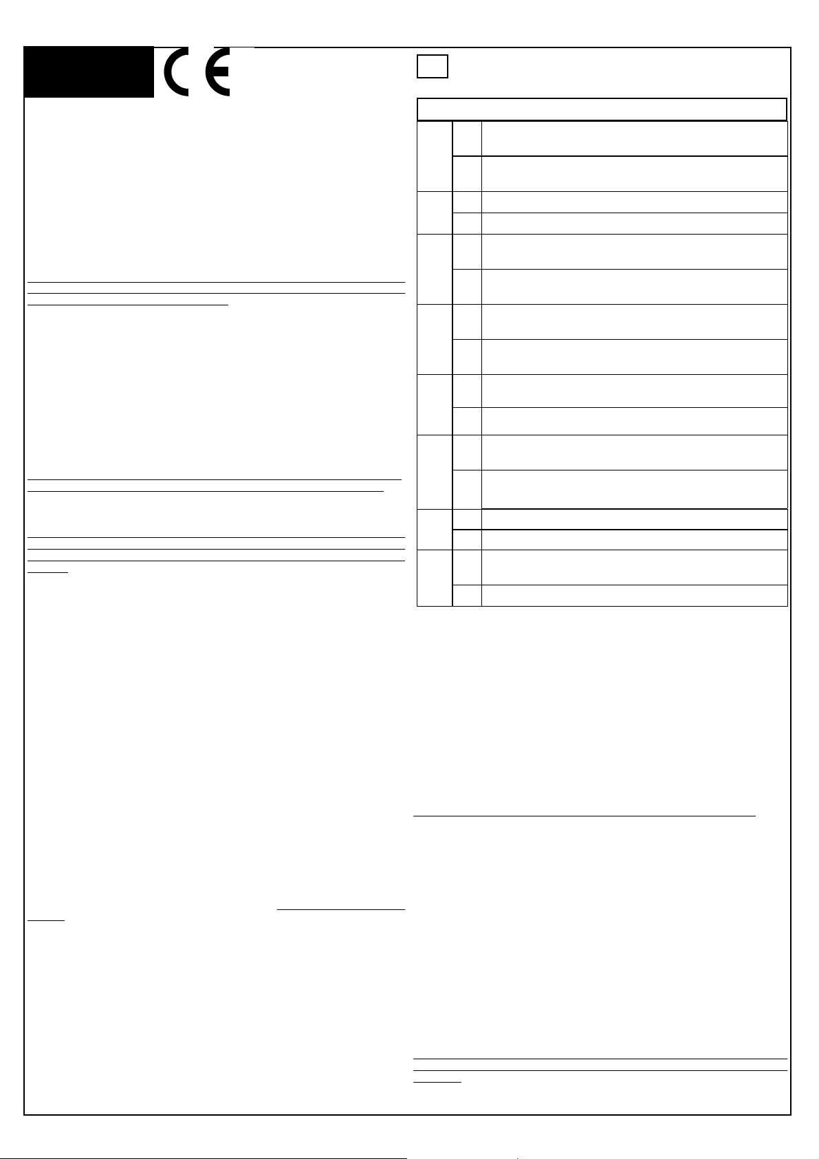
ELECTRICAL SYSTEM CONFIGURATION
(See fig. 1)
IMPORTANT: Any installation, maintenance, cleaning or repair operations on any part
of the automatism must be performed exclusively by qualified personnel, and all such
operations must be performed only after first disconnecting the power supply. Always
keep the 230V cables (power supply, motor, starting condenser, flashing light, courtesy
light) separate from the low voltage cables (controls, electric lock, antenna, and auxiliary power supply) and fasten these latter using adequate clamps near the terminal
boards. Install a multiple pole switch with a contact opening of 3 mm provided with
protection against overloads upstream from the automatism. Use a cable with a minimum section of 3X1.5 mm² (such as H07RN-F type) for the power supply and scrupulously respect all the regulations in force regarding electrical systems in the nation of
installation.
TERMINAL BOARD CONNECTION:
(See fig. 1)
1-2: Power supply: 230V AC +/-10% 50 Hz (F = phase, N = neutral)
3-4 Courtesy light output 230 V AC 50 Hz max 40W (DIP8 = ON)
Gate open indicator light output: 230 V AC 50 Hz max 40W (DIP8 = OFF)
5-6 Flashing light output: 230 V AC 50 Hz max 40W
7-8-9 Motor output (7 = open, 8 = common, 9 = close)
10-11 electric lock output 12V AC 15VA
12 Common inputs
13 FCA opening limit-switch input (N.C.) stops the motor's opening stroke
14 FCC closing limit-switch input (N.C.) stops the motor's closing stroke
15 APRE PEDONALE opens the gate to a width of only 1.5 (N.O.)
16 FOTO Photocell Art. 104/105 input (N.C) inverts movement during closing, and
if enabled during opening stops movement
17 STOP stop button input (N.C) stops movement in any situation
18 APRE open/close button input (N.O.) can function in both step-by-step mode
and inversion mode
IMPORTANT: All N.C. inputs not used must be bridged towards the common inputs
terminal.
19 Antenna ground
20 Antenna signal
21-22 Auxiliary power supply output: 24V AC max 200mA
J3 Radio receiver plug-in connector
OPERATION:
TIME SETTING
TCA trimmer for the setting of the automatic closing time, after which the gate will
automatically close again.
TLAV trimmer for the setting of the work time, after which the motor will stop during
both opening and closing.
Whenever the limit-switches are installed, the work time must be set to a value
that is a few seconds higher than the real time required for the stroke of the
motor.
GB
DIP-SWITCHES FUNCTIONS
ON
DIP1
DIP2
DIP3
DIP4
DIP5
DIP6
DIP7
DIP8
FORCE ADJUSTMENT
The 203_2 control panel is equipped with a device that permits the electronic adjustment of motor force by adjusting the “forza” trimmer:
“FORZA”:adjusts the intensity of the motor force during the stroke (rotate
clockwise to increase force, counter-clockwise to decrease force).
The motor force must be adjusted by keeping trimmer R32 “SENS” in
the MIN. position (entirely in clockwise direction) in order to avoid
the undesired intervention of the REVERSER. The sensitivity of the
reverser is made subsequently (see "Reverser operation”).
REVERSER OPERATION
Whenever the “reverser” device is used, the limit-switches must also be installed
After setting the motor force, proceed to the setting of reverser sensitivity. Make sure
that the reverser is enabled (DIP7 OFF) and with the sensitivity set at minimum level
(trimmer R32 turned entirely clockwise) perform an opening movement. During closing,
stop the gate and slowly increase the reverser sensitivity (trimmer R32 turned counterclockwise) until the reverser intervenes (inversion of direction of movement). This
permits the identification of the sensitivity necessary for the intervention of the reverser as soon as the motor stops.
In any case, we recommend setting a sensitivity that is SLIGHTLY lower in order to
avoid the undesired intervention of the reverser by mechanical friction.
The position of DIP2 determines the reaction to the perception of the obstacle, and in
particular:
“collectivity” function enabled: does not receive opening pulses
during opening and the gate open pause time
OFF
“collectivity” function disabled: receives opening pulses also during
opening and the gate open pause time
ON See description “reverser operation”
OFF
See description “reverser operation”
ON “step-by-step” program: OPEN->opening, OPEN->stop, OPEN-
>closing...
OFF
“inversion” program: OPEN->opening, OPEN->closing, OPEN>opening...
ON Sliding version: closing limit-switch delay disabled, anti-inertia de-
vice enabled
OFF
Garage door version: closing limit-switch delay enabled, anti-inertia
device disabled
ON Photocell operative also during opening: stops all movement until the
obstacle is removed
OFF
Photocell operative only during closing: inverts direction of movement
ON automatic closing disabled: after opening, it closes again only after
an opening pulse
automatic closing enabled : after opening, and after the pause time
OFF
set, the gate automatically closes again
ON Reverser disabled
OFF
Reverser enabled.
ON Terminals 3-4: courtesy light output 230V AC 50 Hz (delay: 50 sec-
onds)
OFF
Terminals 3-4: gate open signal light output, 230V AC, 50 Hz
IMPORTANT: limit-switches compulsory
• DIP 2 ON : during both opening and closing, the intervention of the reverser
inverts the direction of movement for 3 seconds and then stops it.
• DIP 2 OFF : during opening, the intervention of the reverser stops movement,
and during closing inverts the direction of movement.
It is in any case obligatory to use appropriate safety devices in order to ensure the
impact force limitation values prescribed by the regulations in force in the nation of
installation.
Page 3

fig. 1
A
24Vac OUTPUT
M4
R22
F1
FORZ
M5
R32-SENS
R1-TLAV
R2-TCA
ANTENNA
ANTENNE
ANTENNA
ANTENA
RG58
ANTENA
19 2021 22
M3
1 2 3 4 5 6 7 8
18
17
16
15
14
13
12
11
10
2 X 0,5 mm²
APRE N.O.
4 X 0,5 mm²
STOP
PED. N.O.
N.C.
START/APRE
START/OUVRE
START/OPEN
START/ABRE
START/ABRE
BLOCCO
BLOCAGE
STOP
BLOQUE
BLOQUEIO
START PEDONALE
OUVERTURE PIETONS
PEDESTRIAN OPEN
APERTURA PEATONAL
APERTURA PEATONAL
INTERRUTTORE ONNIPOLARE
INTERRUPTEUR OMNIPOLAIRE
OMNIPOLAR CIRCUIT BRAKER
INTERRUPTOR OMNIPOLAR
INTERRUPTOR OMNIPOLAR
2 X 1,5 mm²
3 X 1,5 mm²
F2
1 2 3 4 5 6 7 8 9
M1
L
N
FCA
N.C.
FINECORSA APERURA
BUTÉE DE FIN DE COURSE EN OUVERTURE
2 X 1,5 mm²
OPENING LIMIT SWITCH
FIN DE CARRERA ABERTURA
FIM DE PERCURSO ABERTURA
LAMPEGGIANTE 230Vac 50Hz 40W max
CLIGNOTEUR 230Vac 50Hz 40W max
FLASHING LIGHT 230Vac 50Hz 40W max
LAMPARA INTERMITENTE 230Vac 50Hz 40W max
PISCA - PISCA 230 V. c. a. 50 Hz máx. 40W
M
TX
M2
2
1
3 X 1 mm²
FCC
N.C.
2 X 1mm²
3 X 0,5 mm²
FINECORSA CHIUSURA
BUTÉE DE FIN DE COURSE EN FERMETURE
CLOSING LIMIT SWITCH
FIN DE CARRERA CIERRE
FIM DE PERCURSO FECHAMENTO
2 X 0,5 mm²
FOTOCELLULA art. 104 / 105
PHOTOCELLULE art. 104 /105
POHOTOCELL item 104 /105
FOTOCELLULA art. 104 / 105
FOTOCÉLULA art. 104/105
2 X 0,5 mm²
ELETTROSERRATURA 12Vac 15VA
SERRRURE ELECTR. 12Vac 15VA
ELECTRIC LOCK 12Vac 15VA
ELECTROCIERRE 12vaC 15VA
FECHADURA ELÉCTRICA
RX
N.C.
1 2 3 4 5
LUCE DI CORTESIA / SPIA CANCELLO APERTO 230Vac 50Hz 40W max
LAMPE DE COURTOISIE / VOYANT PORTAIL OUVERTE 230Vac 50Hz 40W max
COURTESY LIGHT / OPEN GATE WARNING LIGHT 230Vac 50Hz 40W max
LUZ DE CORTESIA / INDICADOR LUMINOSO PUERTA ABIERTA 230Vac 50Hz 40W max
LUZ DE CORTESIA / INDICADOR LUMINOSO PORTÃO ABERTO 230 V. c. a. 50 Hz máx. 40 W
ATTENZIONE: DEA SYSTEM ricorda tuttavia che la scelta ,la disposizione e l’installazione di tutti i dispositivi e materiali che compongono l’intera automazione deve avvenire in ottemperanza alle normative vigenti nel paese in cui si effettua l’installazione.
ATTENTION: DEA SYSTEM vous rappelle toutefois que le choix, la disposition et l’installation de tous les dispositifs et de tous les matériels qui font partie de l’automation complète doivent être exécutés
conformément aux réglementations en vigueur dans le pays où l’installation sera mise en place.
ATENCIÓN!: DEA SYSTEM, no obstante, recuerda que la elección, la disposición y la instalación de todos los dispositivos y materiales que componen el automatismo debe efectuarse en el cumplimiento
de las normativas en vigor en el país en el que se efectúa dicha instalación.
WARNING: DEA SYSTEM reminds however that the choice and installation of all devices and materials included in the complete automation must respect the legal norms in force in the country where the
system is installed
ATENÇÃO: Entretanto o DEA SYSTEM lembra que a escolha, a disposição e a instalação de todos os dispositivos e materiais que constituem a inteira automação, devem ser efectuadas a obedecer
também as normas em vigor no país onde for instalada.
 Loading...