

Page 1
Operating instructions and warnings
124RR
Control board 24V for gate automation operating
Instructions and warnings
INDEX
OVERVIEW ................................................................................................................................12
1 PRODUCT CONFORMITY .....................................................................................................12
2 WARNINGS..........................................................................................................................12
3 MODELS AND CONTENTS OF THE PACKAGE .......................................................................13
4 PRODUCT DESCRIPTION ......................................................................................................13
5 TECHNICAL DATA.................................................................................................................14
6 OPERATING CONDITIONS ...................................................................................................14
7 ASSEMBLY AND WIRING INSTRUCTIONS ..............................................................................14
8 USE INSTRUCTIONS .............................................................................................................15
8.1 Visualization of inputs status .......................................................................................15
8.2 Set-up and memorization of the motor stroke ..............................................................16
8.3 Built-in radio receiver..................................................................................................16
8.4 Personalization of working parameters ........................................................................18
8.5 Reset of default parameters (p.007).............................................................................18
8.6 Safety devices .............................................................................................................18
8.7 Messages shown on the display...................................................................................19
9 MAINTENANCE ....................................................................................................................20
10 PRODUCT DISPOSAL............................................................................................................20
11 COMPLETE CLOSING ASSEMBLY...........................................................................................20
ENGLISH
OVERVIEW
These instructions were prepared by the manufacturer and are an integral part of the product. The
operations described are designed for adequately trained and qualified personnel and must be carefully
read and kept for future reference.
1 PRODUCT CONFORMITY
The 124RR programmable control board bears the EC label. DEA SYSTEM guarantees the conformity
of the product to European Directives 89/336/CE and subsequent amendments (concerning electromagnetic compatibility), 73/23/CE and subsequent amendments (low voltage electrical equipment)
2 WARNINGS
12
tuations.
WARNING DEA System reminds all users that the selection, positioning and installation of all materials
and devices which make up the complete automation system, must comply with the European Directives
98/37/CE (Machinery Directive), 89/336/CE and subsequent amendments (electromagnetic compatibility), 73/23/CE and subsequent amendments (low voltage electrical equipment). In order to ensure a
suitable level of safety, besides complying with local regulations, it is advisable to comply also with the
above mentioned Directives in all non-European countries.
WARNING Using the product under unusual conditions not foreseen by the manufacturer may cause
dangerous situations; this is the reason why all the conditions prescribed in these instructions must be
followed.
WARNING Under no circumstance must the product be used in an explosive environment or surroundings that may prove corrosive and damage parts of the product.
Read these warnings carefully. Failure to respect the following warnings may cause risk si-
A1
A2
A3
R
124 RR
Page 2
Operating instructions and warnings
WARNING To ensure an appropriate level of electrical safety always keep the 230V cables (power supply) apart from low voltage cables (motors power supply, controls, aerial and auxiliary circuits power
supply), and fasten the latter with appropriate clamps near the terminal boards.
WARNING Any installation, maintenance or repair operation on the whole system must be carried out
exclusively by qualified personnel. All these operations must be performed only after disconnecting the
power supply, and operating in strict compliance with the electrical standards and regulations in force
in the nation of installation.
WARNING Install and wire the control board according to the instructions given in the instruction
booklet of each gate operator DEA System (such as hole drilling to allow for wires passage, use of wire
clamps, etc.) Failure to comply with these instructions may jeopardize the level of electrical safety.
WARNING During motor stroke memorization, the control board detects automatically the presence
and type of photocells, safety devices and limit switches which are installed. It is therefore essential that
during this phase the latter be properly connected and working.
WARNING Wrong assessment of impact forces may cause serious damage to people, animal and
things. DEA System reminds all personnel that the installer must ascertain that these impact forces,
measured according to EN 12245 prescriptions, are actually below the limits indicated by EN12453
regulation.
WARNING Any external safety device installed in order to conform to the limits set for impact forces
must comply with EN12978.
A4
A5
A6
A7
A8
A9
WARNING Using spare parts not indicated by DEA System and/or incorrect re-assembly may endanger
people, animals and property, and may also cause malfunctioning of the product: always use parts
provided by DEA System and follow assembly instructions.
A10
WARNING Disposal of packaging materials (such as plastic, card board, etc.) must be done according
to regulations in force locally. Do not leave plastic bags and polystyrene within the reach of children
A11
3 MODELS AND CONTENTS OF THE PACKAGE
The control board 124RR is available with DEA System gate operators for overhead doors, sliding
gates as well as barriers, or individually as spare part for the above mentioned gate operators.
4 PRODUCT DESCRIPTION
124RR control board is designed for the automation of DEA System gates operators in 24 V d.c., and
therefore it is fit for overhead doors, sliding gates and barriers. It is extremely versatile, easy to install and
fully complies with European regulations concerning electromagnetic compatibility and electric safety
Main features of the product:
1. setting all parameters by 3 keys and a 4-digit display;
2. possibility of fine tuning of motor speed both during its complete stroke and during the last phase of it
(slow-down). It keeps motor torque even at very low speed;
3. possibility to set at will the slow-down duration;
4. Internal anti-crash safety device whose sensitivity can be adjusted (according to a 70-level scale) sepa-
rately in both operating directions;
5. inputs to connect both normal and powered external safety devices (mechanical ribs or photocell bar-
riers), with the possibility to run a self-test before each operation. Controlled photocells;
6. built-in 433,92MHz radio receiver for both HCS and HT12E coding offering the possibility to search
and delete each transmitter separately
13
124 RR
R
Page 3
Operating instructions and warnings
WARNING DEA System reminds all users that the selection, positioning and installation of all materials
and devices which make up the complete automation system, must comply with the European Directives
98/37/CE (Machinery Directive), 89/336/CE and subsequent amendments (electromagnetic compatibility), 73/23/CE and subsequent amendments (low voltage electrical equipment). In order to ensure a
suitable level of safety, besides complying with local regulations, it is advisable to comply also with the
above mentioned Directives in all non-European countries.
5 TECHNICAL DATA
Power supply ....................................................230 V a.c. +/- 10% 50Hz
Flashing light output .........................................24 V d.c. max 15W art. Lumy 24S
Auxiliary power supply output (+24VAUX) ..........24 V d.c. (max 200mA)
Safety devices power supply output (+24VSIC) ...24 V d.c. (max 200mA)
LC/SCA contact capacity LC/SCA ......................max 5A
Max motor capacity ..........................................70W max
Fuse F1 ............................................................T1A 250V (retarded)
Fuse F2 ............................................................T10A 250V (retarded)
Radio receiver frequency ...................................433,92 MHz rolling code / dipswitch coding
Max. number of transmitter controlled................100
A1
6 OPERATING CONDITIONS
124RR control board is designed for the automation of DEA System gates operators in 24V a.c., and
therefore it is fit for overhead doors, sliding gates and barriers.
This control board is designed and tested for operation under “normal” conditions for both residential
and industrial use. The level of protection against dust and water and other data are illustrated in the
instructions booklet of each gate operator DEA System, equipped with the 124RR control board.
WARNING Using the product under unusual conditions not foreseen by the manufacturer may cause
dangerous situations; this is the reason why all the conditions prescribed in these instructions must be
followed.
WARNING Under no circumstance must the product be used in an explosive environment or surroundings that may prove corrosive and damage parts of the product.
ASSEMBLY AND WIRING INSTRUCTIONS
WARNING To ensure an appropriate level of electrical safety always keep the 230V cables (power supply) apart from low voltage cables (motors power supply, controls, aerial and auxiliary circuits power
supply), and fasten the latter with appropriate clamps near the terminal boards.
WARNING Any installation, maintenance or repair operation on the whole system must be carried out
exclusively by qualified personnel. All these operations must be performed only after disconnecting the
power supply, and operating in strict compliance with the electrical standards and regulations in force
in the nation of installation.
WARNING Install and wire the control board according to the instructions given in the instruction
booklet of each gate operator DEA System (such as hole drilling to allow for wires passage, use of wire
14
clamps, etc.) Failure to comply with these instructions may jeopardize the level of electrical safety.
Connect to the power supply 230 V a.c. ± 10% 50 Hz through a multi pole switch or a different device
that can ensure multi pole disconnection from the power supply, with a contact opening of 3 mm. Use a
cable with a minimum section of 3 x 1,5 mm² (e.g. a H07RN-F type).
Make all connections to the terminal board and remember to short-circuit, whenever necessary, all
unused inputs. (See table 1 terminal board connection and Fig. 1 wiring diagram)
A2
A3
A5
A6
R
124 RR
Page 4
Operating instructions and warnings
F
C
A
PE
D
ST
A
RT
FCC
FOT
O
ST
O
P
SIC
Table 1 Terminal board connection
1-2 24 V a.c. 24 V a.c. transformer power supply input
3-4
24 V Batt 24 V d.c. battery power supply input (Follow carefully polarity indications)
5-6
LC/SCA
7-8
LAMP
9
COM Common safety devices
9-10
+24VAUX
9-11
+24VSIC
12-13
14
FCA N.C. input limit switch while opening. If unused, short circuit to terminal n° 21
Free contact max. capacity 5 A : this contact can be used to control an open gate
warning light (P27=0) or a courtesy lamp (P27≠0)
Flashing light output 24 V d.c. max 15W art. Lumy 24S The intermittent output does not
demand the use of a flashing light card.
+24 V d.c. power supply output for controlled safety devices. To be used as power
supply of photocell transmitters (in all cases) and of safety devices when testing these
latter before each operation
+24 V d.c. power supply output for auxiliary circuits and uncontrolled safety devices To
be used as power supply of any auxiliary devices, photocell receivers (in all cases), and
of safety devices when testing these latter before each operation
Motor output 24 V d.c. max 70W
M
15
16
FCC N.C. input limit switch while closing. If unused, short circuit to terminal n° 21
START N.O. open input. If activated, it opens or closes both motors. It can work in “reversal”
mode (P25=0) or “step-by-step” mode (P25=1)
17
PEDON N.O. pedestrian opening input. If activated, it opens the motor
18
STOP N.C. stop input. If activated, it stops the movement of both motors during any opera-
tion. If unused, short circuit to terminal n° 21
19
FOTOC
N.C. Photocell input. In case of activation it reverses the movement only while closing
(P26=0) or it reverses the movement while closing and stops while opening (P26=1).
If unused, short circuit to the terminal n°21
20
SIC
21
COM Common inputs
22
23
N.C. leaf safety device input. In case of activation it reverses the movement (P18=0) or
it stops it (P18=1). If unused, short circuit to the terminal n°21
Aerial ground input
Aerial signal input
8 USE INSTRUCTIONS
Press on the “OK” key to check if all inputs have been properly connected.
After making all connections to the terminal board, remember to short-circuit, whenever needed, any
unused input (see “connection to the control board”) and power the card: on the display you will read for
a few seconds “rES-” followed by the symbol “----” which stands for gate closed.
15
8.1 Visualisation of inputs status
R
124 RR
Page 5

Operating instructions and warnings
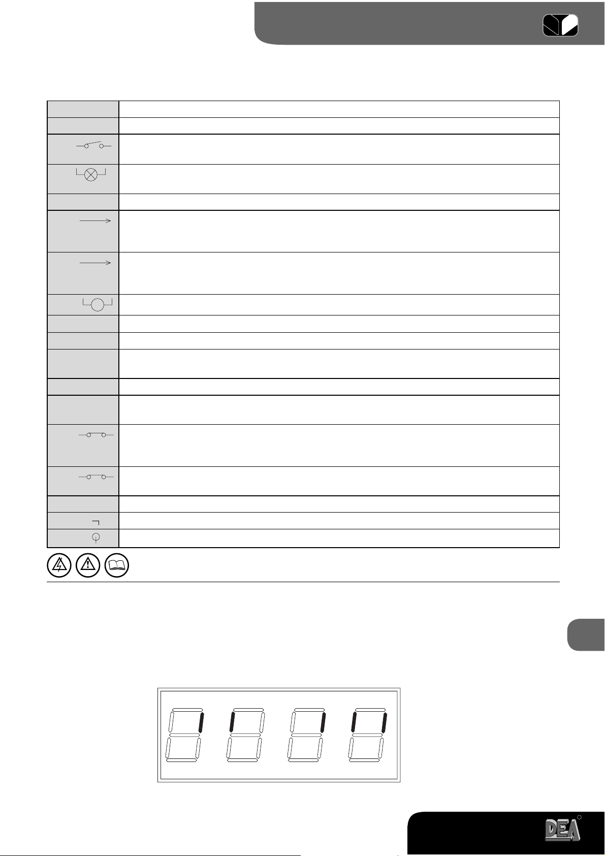
By pressing on the “OK” key when the control board awaits further instructions (“----”), the display shows
some vertical segments: each one of them is associated to one of the control board inputs (see the picture
above). When the segment is lighted it means that the contact associated to it is closed, on the contrary,
when it is switched off the contact is open. You can now position the door/gate in its position of max.
opening. In order to do this:
8.2 Setup and memorization of motor stroke
WARNING During motors stroke memorisation, the control board detects automatically the presence
and type of photocells, safety devices and limit switches which are installed. It is therefore essential that
during this phase the latter be properly connected and working.
A7
Instructions Function
The control board is ready to receive instructions
Door/gate positioning
Scroll down the parameters until you visualize procedure P001
Confirm! The control board is ready for the positioning of the door/gate
Position the door/gate in its standstill position while opening
1
Confirm! The control board has memorized the door/gate position
Motors stroke memorization
Scroll down the parameters until you visualize procedure P003
Confirm! The control board awaits a further confirmation
Confirm by pressing on the OK key for a few seconds! The procedure starts
Now the door/gate starts to close in the slow down phase until it
reaches the stroke end while closing (or the limit switch).
On the display you will read “P003”. Motor stroke memorization done!
Scroll down the parameters until “----”. The control board awaits further instructions
Display
1
By pressing on the key the door/gate must open, by pressing on the key the door/gate must close. If this does not
happen, you must swap the two motor cables (terminals 7 and 9) Only if you use limit switches, first position the door/gate
where you want it to stop in closing and then adjust the closing cam so that it presses on the limit switch associated to it in
that point. Then position the door/gate in the opening position and adjust the opening cam so that it presses on the limit
switch associated to it in that point.
8.3 Built-in radio receiver
DEA 124RR control board includes a 433,92MHz built-in radio receiver accepting both transmitters with
16
HCS coding (complete rolling code or just fixed part), and HT12E dip-switch coding.
•The type of coding is selected by programming the working parameter n° 8 “type of coding” (see Table
2 Parameters)
•The receiver memory capacity can contain up to 100 different transmitters.
•When receiving a pulse from the transmitter, depending on your channel selection and linking, the start
or the pedestrian inputs are activated. In fact, by programming one of the working parameters it is
possible to choose, according to one’s needs, which key of the memorized transmitters will activate the
start input and which one will activate the pedestrian input (see “4. Channel selection and linking on
the transmitter”).
•While you memorize each transmitter the display shows a progressive number by which you will be able
to trace and, if necessary, delete each transmitter individually
R
124 RR
Page 6

Operating instructions and warnings
Instructions Function
The control board is ready to receive instructions
Deletion of all transmitters
Scroll down the parameters until you visualize P004
Confirm! The control board awaits a further confirmation
Confirm by pressing on the OK key for a few seconds! The procedure starts
Done! The transmitters memory has been deleted
Scroll down the parameters until you visualize “----”. The control board awaits
further instructions
Memorization of transmitters
Scroll down the parameters until you visualize P005
Confirm! The receiver enters in memorization mode
The flashing light turns on
Press on any key of the transmitter.
Memorization done! The flashing light goes out for 2 seconds. The display
visualizes the number of the transmitter just memorized (es. “r001”)
The receiver reverts automatically to memorization mode
The flashing light turns on again
Display
1
Memorize all necessary transmitters
Wait 10 seconds before quitting the memorization mode
The receiver will now receive all the memorized transmitters
How to activate the memorization mode without
Operating on the control board
1
Press simultaneously on key CH1 and CH2, or on the hidden key of a
transmitter already memorized
How to search and delete a transmitter
Scroll down the parameters until you visualize P006
Confirm! You can now select the transmitter
Scroll down the transmitter numbers until you reach the transmitter to be deleted (eg. “r003”)
Confirm the deletion by pressing the OK key for a few seconds
17
OK! The transmitter is deleted
You can now select the parameter
Scroll down the parameters until you visualize “----”. The control
board awaits further instructions
1
Make sure that the receiver is set to receive the type of coding of the transmitter you wish to memorize: visualize and, if
necessary, update parameter n° 8 “type of coding” (see “8.4 Personalization of working parameters “)
124 RR
R
Page 7

Operating instructions and warnings
Channel selection and linking on the transmitter
The built-in receiver can control both the start input and the pedestrian one. By setting the correct value
of the parameter “P009 Selection and linking of channels” it is possible to decide which key of the transmitter will activate each input.
If you check on the “working parameters” table you will realize that the P009 parameter allows you to
choose among 16 different combinations. If, for instance, you attribute value “3” to the parameter P009,
all memorized transmitters will activate the start input through the CH1 and the pedestrian input through
CH4. Please refer to chapter “8.4 Personalization of working parameters” in order to select your own
combination.
8.4 Personalization of working parameters
Instructions Function
Display
The control board is ready to receive instructions
Scroll down the parameters until you visualize the one you wish to set (ex. P010)
Confirm! The display shows the set parameter value
Increase or decrease the value until you reach the value you wish to define
Confirm! The display shows again the parameter
Scroll down the parameters until you visualise “----”. The control board awaits
further instructions
The automation is now ready to work according to the new working parameters.
8.5 Resetting of default parameters (p.007)
DEA 124RR control board software includes a reset procedure to restore default values (the one set by
the maker) of all settable parameters. The value originally set for each parameter is shown in the “working
parameters table”. In case you should reset all values and restore all default values, proceed as follows:
Instructions Function
Display
The control board is ready to receive instructions
Scroll down the parameters until you visualize P007
Confirm! The control board awaits a further confirmation
Confirm by pressing on the OK button. The procedure starts
All parameters are now set at their original value
Scroll down the parameters until you visualise “----”. The control board awaits
further instructions
8.6 Safety devices
DEA 124RR control board allows fitters to set up installations that truly comply with European regulations concerning automated garage doors and gates. More specifically, this control board allows you to
comply with the limits set by the same regulations as to impact forces in case of collision with obstacles.
18
DEA 124RR control board is equipped with a built-in anti-crush safety device that, associated to the
possibility of tuning up the motors’ speed, allows you to comply with the limits imposed by the above
mentioned regulations in most installations.
In particular, you can adjust the anti-crush safety device sensitivity by properly setting the value assigned to the following parameters (see also “8.4 Personalization of working parameters “):
•P014 motor 1 force in opening: from 30 (min. force, max sensitivity) to 100 (max force, neutralized sensitivity)
•P015 motor 1 force in closing: from 30 (min. force, max sensitivity) to 100 (max force, neutralized sensitivity)
In case the gate structural features do not allow you to comply with the above force limits, it is possible
to use external safety devices inputs (terminal no. 12). SIC inputs can be configured by properly setting
parameter no. 18:
•P018= 0 “rib” mode functioning: when the input is activated the movement direction of the motors is inverted.
•P018=1“photoelectric barriers” mode functioning: when the input is activated, the motor stops.
R
124 RR
Page 8

Operating instructions and warnings
If SIC input is unused, it is necessary to short circuit it to terminal no. 11.
If you power external safety devices through 24VSIC output (terminal no. 22), their pro-
per working is tested before each manoeuvre.
8.7 Messages shown on the display
124RR control board allows you to visualize on the display several messages concerning its working
status and any malfunction:
Message Description
MESSAGES CONCERNING WORKING STATUS
Gate is closed
Gate is open
Opening under way
Closing under way
While in step-by-step mode, the control board awaits further instructions after a start command
Stop input activated
SIC activated while working in barrier mode
ERROR MESSAGES
Message Description
Possible solutions
They point out that the gate has
exceeded:
- (Err1), the max allowed number of
reversals (50) without ever reaching
the end of stroke (or limit switch) while
closing;
- (Err2) the max number of uninterrupted operations (10) of the anticrush safety device;
Therefore an “emergency maneuver”
is under way: the control board sets
automatically the motors in a slow
down phase and searches the stops
(or limit switches) in order to reset the
positioning system. Once the stops
(or limit switches) while closing are
found again the message disappears
and the control board awaits further
instructions “----” and then resumes
working normally.
External photocells and/or safety devices are activated or out of order
The motor is not connected or it signals control board failure
In case the gate is not properly closed after the
emergency maneuver (maybe because of false
stops or obstacles due to mechanical frictions),
proceed as follows:
- Disconnect the power supply, check manually that
no particular frictions and/or obstacles are present
during the complete stroke of the door/gate. Leave
the door/gate half-open.
- Connect the power supply again and subsequently give a start pulse. At this point the door/gate will
start to close in slow down phase until reaching the
stop (or end of stroke). Make sure that the maneuver is properly completed. Adjust force and motor
speed values, if needed.
If the gate keeps working inappropriately try to
repeat the motor stroke memorization procedure
(see paragraph 8.2)
Make sure that all safety devices and/or photocells
installed are working properly.
Make sure that the motor is properly connected. If
the message reappears change the control board.
19
Control board power supply tension
is out of allowed range
Possible motor overheating due to
obstacles hindering the door/gate
traveling. The control board does not
react to instructions.
Make sure that power supply tension on faston
1-2 is 22 V a.c.+/-10%, and on faston 3-4 is 27
Vd.c.+/-10%.
Remove any obstacle hindering the traveling and
wait until the “bLOC” message replaces the “Err6”
message for the control board to resume accepting
instructions (a few seconds)
R
124 RR
Page 9

Operating instructions and warnings
9 MAINTENANCE
WARNING Any installation, maintenance or repair operation on the whole system must be carried out
exclusively by qualified personnel. All these operations must be performed only after disconnecting the
power supply, and operating in strict compliance with the electrical standards and regulations in force
in the nation of installation.
A5
WARNING Using spare parts not indicated by DEA System and/or incorrect re-assembly may endanger
people, animals and property, and may also cause malfunctioning of the product: always use parts
provided by DEA System and follow assembly instructions.
A9
10 PRODUCT DISPOSAL
WARNING Disposal of packaging materials (such as plastic, card board, etc.) must be done according
to regulations in force locally. Do not leave plastic bags and polystyrene within the reach of children
Demolition of this product does not cause particular dangers. Whenever the regulations in force in the
country of installation demand it, it is always advisable and necessary to dispose suitably and separately
of each material that make up the product: plastic, ferrous materials, batteries and electric parts.
A5
11 COMPLETE CLOSING ASSEMBLY
Remember that everyone who sells and/ or motorises doors/gates becomes the manufacturer of the
automated door/gate machine, and must therefore prepare and preserve a technical folder containing
the following documents (see Machinery Directives Enclosure V).
• Assembly drawing of the automatic door/gate.
• Electrical connection and control circuit diagram.
• Risk analysis including: a list of the essential safety requirements provided in machine Directive Enclosu-
re I; a list of the risks posed by the door/gate and a description of the implemented solutions
The installer must also:
• Keep these operating instructions and the instructions for all other components in a safe place.
• Prepare the operating instructions and general safety warnings (by filling up these operating instruc-
tions) and hand a copy to the end user.
• Fill in the maintenance handbook and hand a copy to the end user.
• Draw up the EC declaration of conformity and hand a copy to the end user.
• Fill in the complete EC label or plate and apply it to the automated door/gate.
N.B. The technical folder must be kept for inspection by the competent national authorities for at least ten
years starting from the date of the automatic door/gate manufacturing.
WARNING DEA System reminds all users that the selection, positioning and installation of all materials
20
and devices which make up the complete automation system, must comply with the European Directives
98/37/CE (Machinery Directive), 89/336/CE and subsequent amendments (electromagnetic compatibility), 73/23/CE and subsequent amendments (low voltage electrical equipment). In order to ensure a
suitable level of safety, besides complying with local regulations, it is advisable to comply also with the
above mentioned Directives in all non-European countries.
WARNING Wrong assessment of impact forces may cause serious damage to people, animal and
things. DEA System reminds all personnel that the installer must ascertain that these impact forces,
measured according to EN 12245 prescriptions, are actually below the limits indicated by EN12453
regulation.
WARNING Any external safety device installed in order to conform to the limits set for impact forces
must comply with EN12978.
R
124 RR
Page 10

Operating instructions and warnings
2
USER
3
3
3
3
..100
CH3 CH4
CH4 CH1
CH4 CH2
CH4 CH3
CH1 CH2
CH2 CH2
CH3 CH2
CH4 CH2
..100
1
HCS fixed part only
HCS rolling code
HT12E dip switch
001
000
002
009
start Pedest. start Pedest.
CH1 CH2
001
010
CH1 CH3
002
011
CH1 CH4
003
012
CH2 CH1
004
013
CH2 CH3
005
014
CH2 CH4
006
015
CH3 CH1
007
016
CH3 CH2
008
50 ....................... 100
30............ 60.................. 100
.........50
10 ....25
“safety rib” mode
“photoelectric barrier” mode
001
30..............................90
30..............................90
000
Positioning of the door/gate
Unused parameter
Memorization of the motors’ stroke
Deletion of the radio receiver memory
Transmitters memorization
Search and deletion of a transmitter
PROCEDURE DESCRIPTION
P001
P002
P003
P004
P005
Resetting of default parameters
P006
P007
PROCEDURE
Type of coding of the radio receiver
PARAMETER DESCRIPTION SETTABLE VALUES
P008
Channel selection and linking to “start” and “pedestrian” inputs
P009
Slow-down duration (expressed as % of total stroke)
Motors’ speed during normal stroke (calculated as % of max speed)
Motors’ speed during slow-down phase (calculated as % of max speed)
P011
P010
PARAMETRES
Unused parameter
P012
P013
Motor’s force while closing (if = 100 --> max force, sensitivity on obstacle excluded)
Motor’s force while opening (if = 100 --> max force, sensitivity on obstacle excluded)
P015
P014
Unused parameter
Selection of type of external safety device: rib / barrier. If the “rib” modality is selected,
the SIC input activation inverts the movement direction; during slow-down phase, while
P016
P017
P018
21
if the “barrier” modality is selected the movement is stopped.
R
124 RR
Page 11

Operating instructions and warnings
deactivated
activated
deactivated
activated
reversal
step-by-step
Photocell activated only in closing
Photocell activated also in opening
deactivated
activated
pedestrian
fast ramp
centralized closing
separate closing
slow ramp
0 10 .............................................. 255
0..... 2 .............................................. 15
000
001
000
001
000
001
000
001
0.................................................... 255
000
001
000
001
>001
000
001
0...................................................... 10
0...................................................... 10
22
Unused parameter
Unused parameter
Time of pre-flashing (expressed in sec)
Time of automatic closing (expressed in sec). If = 0 the automatic closing is deactivated
P020
P019
R
Collectivity function: if it is activated it deactivates both start and pedestrian inputs for
the whole duration of automatic opening and closing
Ram blow function: if it is activated, it pushes the motors closed for one second before
each opening movement, so as to ease motor’s start
Operating program: reversal (start->open, start->close, start->open ...), step-by-
P021
P022
P023
P024
step (start->open, start->stop, start-close...)
Photocell function even while opening: if it is activated, the photocell stops the movement
P025
P026
Clean contact operation :
- If = 0, open gate warning light, the contact is always closed when the gate is opened,
it opens again only when the closing movement is completed
- If different from 0, courtesy light, the contact is closed during every movement, it opens
again when the motor stops according to a pre-settable delay (expressed in sec)
while opening until the obstacle is removed. In any case it reverses the direction of
movement while closing
P027
Short reversal at end of stroke: when the door/gate reaches the end of stroke, it reverses
P028
Unused parameter
shortly the movement so as to “release” the mechanical stress due to the door/gate
“PED” input functioning
pressure on the end of stroke itself.
-If = 0 it ensures the door/gate closing in any situation. The input opens and works normally
-If = 1 the “PED” input starts the closing, the “AP” input starts the opening
P029
P030
-If >1 The selected value indicates the duration of the pedestrian stroke (expressed as
a % of the total stroke)
Ramp rate duration
-If =0 the motor starts immediately at the selected speed
-If =1 the motor speeds up progressively until it reaches the selected speed
P031
124 RR
Reaction at detection of an obstacle while opening
- If=0 the door inverses travelling direction
- If different from 0 the door inverses travelling direction only for the set time (expressed in sec)
Reaction at detection of an obstacle while closing
-If=0 the door inverses travelling direction
-If (0 the door inverses travelling direction only for the time set (expressed in sec)
Unused parameter
Column reserved to the installer to fill in with the automation personalised parameters Table 2 Parametres
Inactive channel.
P032
P033
The default value, set by manufacturer at the factory, is written in bold and underlined.
P034
1
2
3
 Loading...