

DCS ADR248 Installation Manual

Professional Access Drawers
ADR models
Installation instructions
and User guide
Tiroirs d’accès professionnel
Modèles ADR
Instructions d’installation
et Guide d’utilisation
US CA


A MESSAGE TO OUR CUSTOMERS
• Closing drawers may cause injury to
your hands or fingers.
• Always close or open drawers using
their handles.
• Be sure to keep hands away from
drawer edges when opening or
closing drawers.
WARNING
Thank you for selecting these DCS by Fisher & Paykel Professional Access Drawers. Because of this product’s unique features
we have developed this Installation Guide. It contains valuable information on how to properly install and maintain your
new Professional Access Drawers for years of safe and enjoyable use.
To help serve you better, please fill out and submit your Product Registration by visiting our website at www.dcsappliances.
com and selecting “Customer Care” on the home page and then select “Product Registration”. In addition, keep this guide
handy, as it will help answer questions that may arise as you use your new Access Drawers.
For your convenience, product questions can be answered by a DCS by Fisher & Paykel Customer Care Representative at
1-888-936-7872, or email: customer.care@fisherpaykel.com.
Note: Please write the model, code, and serial numbers on this page for reference (located on the sticker on the rear brace in
the tank side - see Fig. 04).
Model number Code Serial number
NOTE: Inspect the product to verify that there is no shipping damage. If any damage is detected, call the shipper and initiate
a damage claim. DCS by Fisher & Paykel is not responsible for shipping damage.
DO NOT discard any packing material (box, pallet, straps) until the unit has been inspected.
WARNING
1. Do Not store or use gasoline or other flammable vapors and liquids inside or in the vicinity of this or any other
appliance.
2. An LP cylinder not connected for use shall not be stored inside or in the vicinity of this unit.
FOR YOUR SAFETY
1. Do not allow children or pets to play in or around the Access Drawers.
2. Clean the Access Drawers regularly using a mild dish washing liquid and water.
3. To maintain the exterior appearance, apply a stainless steel polish to the outside surfaces on a regular basis.
4. Sanitize the Access Drawers surfaces each season as necessary.
5. To prevent the formation of mold or mildew, do not store cloth napkins or tablecloths in the Access Drawers for long
periods.
6. Cooking utensils that are stored in the Access Drawers should be stored in
sealable plastic bags and/or washed each time before re-use.
7. To prevent personal injury or damage to the drawers, do not overload them.
The maximum rating per drawer is 75 pounds.
1


TABLE OF CONTENTS
SAFETY PRACTICES & PRECAUTIONS 3
MODEL IDENTIFICATION & DIMENSIONS 4
SHIPPING INSPECTION 5
CABINET PREPARATION 5
INSTALLATION
Make Cutout and Installing Support Structure - 6
Proud installation
Make Cutout and Installing Support Structure - 8
Flush installation
Removing Drawers 10
Slide in Access Drawers and Mount to Support Structure 10
Re-installing Drawers 11
CARE & MAINTENANCE 13
SERVICE 14
SAFETY PRACTICES AND PRECAUTIONS
1. Begin by insuring proper installation and servicing.
2. Follow the installation instructions in this manual.
3. To extend the service life of your product, be sure to follow the use and care guidelines in this manual.
WARNING:
Do not store items of interest to children above or on the inside of any appliance. Children could be seriously
injured if they should climb onto or into the appliance to reach these items.
PLEASE RETAIN THIS MANUAL FOR FUTURE REFERENCE
3

MODEL IDENTIFICATION & DIMENSIONS
ADR2-48
ADR2-36
ADR2-30
ADR2-24
H
D
W
Fig. 1
DIMENSIONS
Model
ADR248 231/2” 48” 217/8” 2”
ADR236 231/2” 36” 217/8” 2”
ADR230 231/2” 30” 217/8” 2”
D W H F
Fig. 1a
F
44
ADR224 231/2” 24” 217/8” 2”
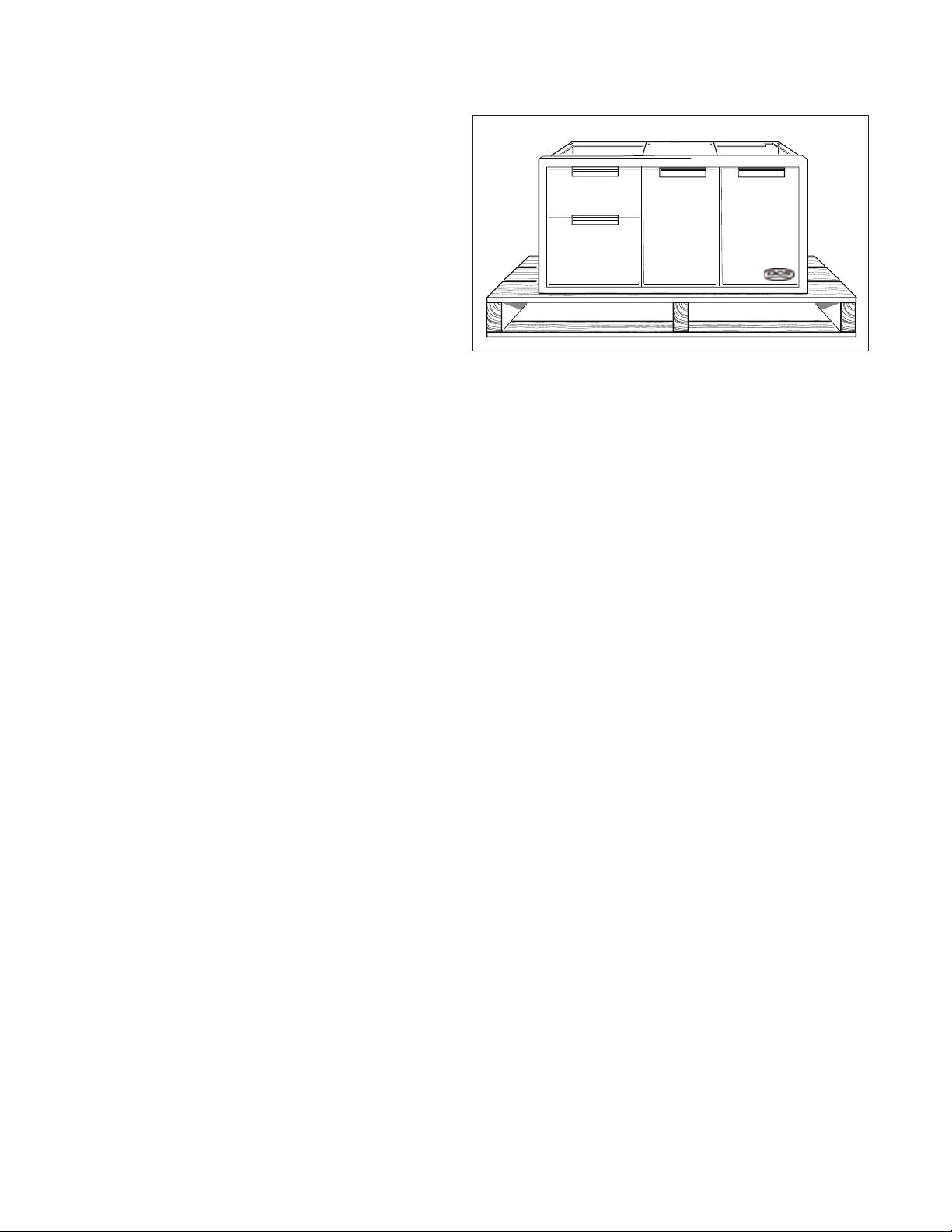
SHIPPING INSPECTION
1. Inspect the Access Drawers to verify that there is no
shipping damage.
2. If any damage is detected, call the shipper and
initiate a damage claim. DCS by Fisher & Paykel is not
responsible for shipping damage.
NOTE: Do not discard any packing material (box, pallet,
straps) until the unit has been inspected.
■ Operate the drawers to be sure they glide smoothly.
■ Examine the drawer fronts to be sure there are no dents or
scratches or discoloring.
Fig. 2
CABINET PREPARATION
■ Cabinet face should be clean and flat.
■ All angles must be at 90º and plumb.
■ Support structure must be resistant to moisture damage.
■ All gas lines and plumbing must be done before installing access drawers.
■ Do not use any harsh products (acid, solvent, sealers) around this unit.
■ Any cabinet and/or ground preparations must be completed prior to installation.
5

INSTALLATION
MAKE CUTOUT AND INSTALL SUPPORT STRUCTURE PROUD INSTALLATION
1. Make a cut-out in your cabinet or island with the following dimensions (Fig. 3A):
NOTE: Each corner of the cutout should be 90º for the Access Drawers to fit properly.
Vent*
Vent*
C
Vent*
A
B
90º
Fig. 3
* Island installation to use minimum of 3 vents
providing 10 sq. in. per vent (typical).
CUTOUT DIMENSIONS
Model
ADR248 46” 20” 1.0” min.
ADR236 34” 20” 1.0” min.
ADR230 28” 20” 1.0” min.
ADR224 22” 20” 1.0” min.
A
0,+1/8”B0,+1/8”
C
Fig. 3A
2. Place 2 X 4s to provide support for the Access Drawers structure in the locations indicated in Fig. 4A.
3. Board lengths are provided in the table Fig. 5A.
6
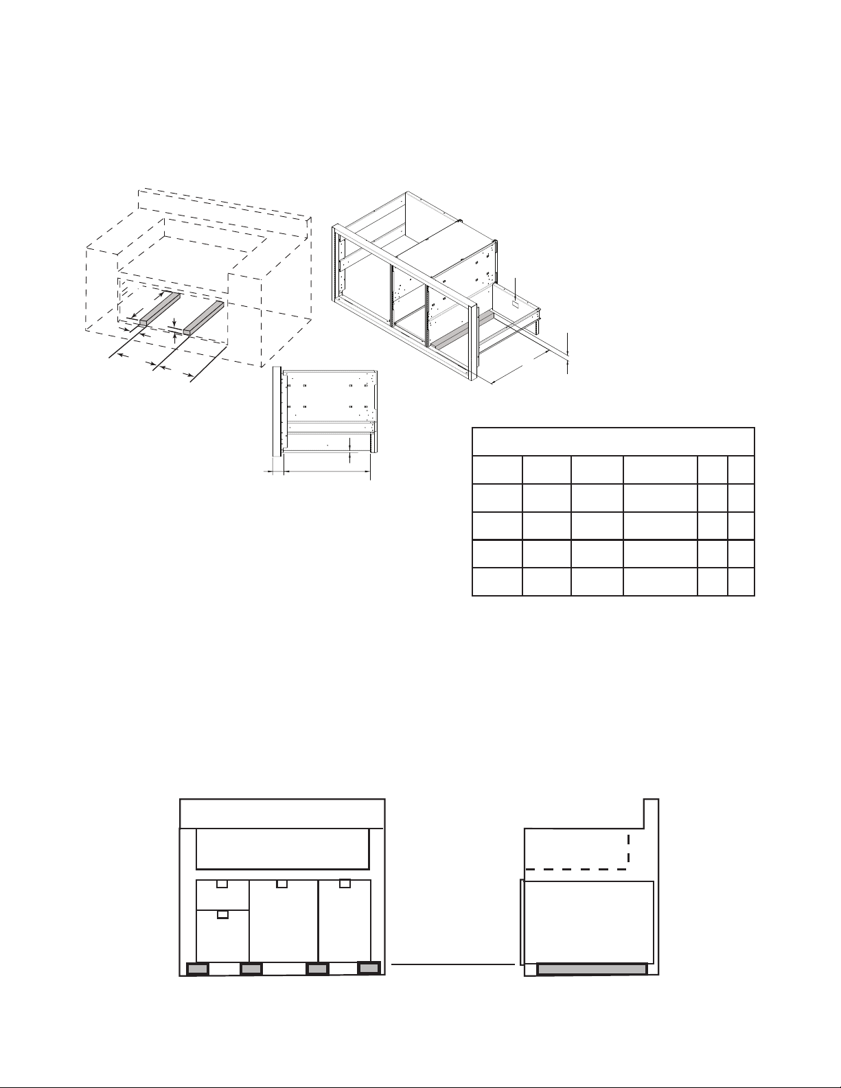
INSTALLATION
To ensure proper drawer operation, be sure
your support boards are flat & level.
A
B
C
E
D
Sticker location of
Model, Serial, Code Number
B
A
2-5/8” 21-1/2" support
Fig. 4A
boards must
t in this area.
1-1/2" Bottom of center divider to
island cutout
*
SUPPORT BOARD DIMENSIONS
Model A B C D E
48” 2 X 20” 11/2”* 31/2” min. 14 12
36” 20” 11/2”* 31/2” min. 14
30” 2 X 20” 11/2”* 31/2” min. 14 12
*Dependent on application. Top of
support boards must be 1/2” above the
bottom edge of the cutout.
4. When installing your support boards, be sure they are level.
5. Ensure that the bottom of the center divider rests on top of the support boards as shown (Fig. 4A).
FRONT VIEW TYPICAL
24” 20” 11/2”* 31/2” min. 14
Fig. 5A
END VIEW TYPICAL
For proper
support & drawer
operation, insure
that support
boards are level
front to back &
Support Board (typical)
side to side.
Support Boards
(typical)
Fig. 6A
7
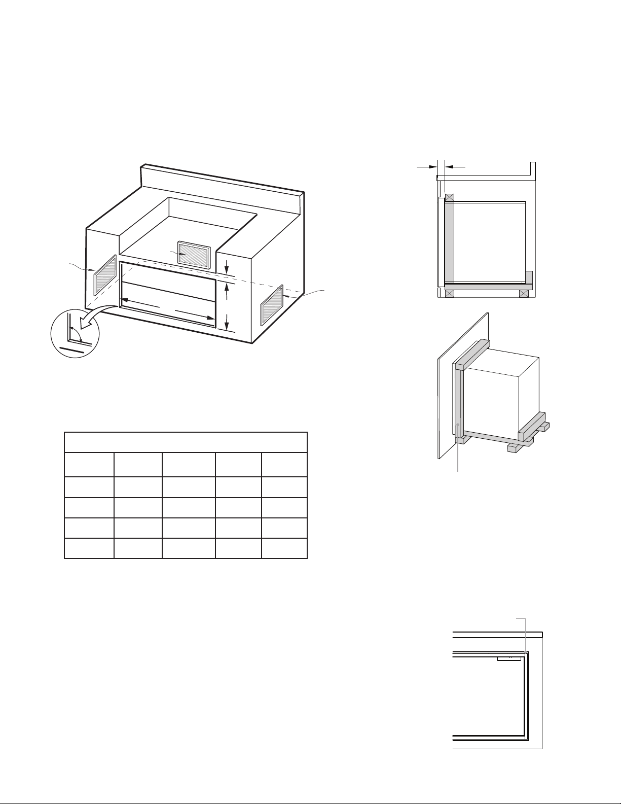
INSTALLATION
D
MAKE CUTOUT AND INSTALL SUPPORT STRUCTURE FLUSH INSTALLATION
1. Make a cut-out in your cabinet or island with the following dimensions:
NOTE: Each corner of the cutout should be 90º for the Access Drawers to fit properly.
2 - 5/8” (67 mm)
D
Vent*
Vent*
C
Vent*
A
B
90º
* Island installation to use minimum of 3 vents
providing 10 sq. in. per vent (typical).
CUTOUT DIMENSIONS
Model
ADR248 48 3/16” 23 11/16” 1.0” min. 1.0” min.
ADR236 36 3/16” 23 11/16” 1.0” min. 1.0” min.
ADR230 30 3/16” 23 11/16” 1.0” min. 1.0” min.
ADR224 24 3 /16” 23 11/16” 1.0” min. 1.0” min.
A
0,+1/8”B0,+1/8”
C D
Fig. 3B
A frame should be constructed 2” (51 mm)
setback from the front face of the product
to both push the product up against and
conceal the cutout clearance around the front
frame.
Important!
Do not seal the product in with silicone caulk or
similiar. Doing so will result in the product being
difficult to remove for servicing.
2. Place 3” X 4”s to provide support for the Access Drawers structure
in the locations indicated in the figure opposite (Fig. 4B).
3. Board lengths are provided in the table opposite (Fig. 5B).
Note: The frame should locate the Access Drawer assembly in the
center of the cutout, and be fastened to the enclosure such that the
unit is reliably secured in place.
8
Minimum 3/16” (4 mm) cutout
clearance around front frame

INSTALLATION
To ensure proper drawer operation, be sure
your support boards are flat & level.
A
B
C
E
D
Sticker location of
Model, Serial, Code Number
B
A
2-5/8” 21-1/2" support
Fig. 4B
*Dependent on application. Top of
support boards must be 1-9/16” above
the bottom edge of the cutout.
FRONT VIEW TYPICAL
Support Board (typical)
boards must
t in this area.
1-9/16" Bottom of center divider to
island cutout
*
SUPPORT BOARD DIMENSIONS
Model A B C D E
48” 2 X 20” 11/2”* 31/2” min. 15 12
36” 20” 11/2”* 31/2” min. 15
30” 2 X 20” 11/2”* 31/2” min. 15 12
24” 20” 11/2”* 31/2” min. 15
Leave a 2” set back for the flush installation.
For proper
support & drawer
operation, insure
that support
boards are level
front to back &
side to side.
Fig. 5B
END VIEW TYPICAL
Support Boards
(typical)
Fig. 6B
9
 Loading...